Baicells Technologies MBS1100 LTE-TDD Base Station User Manual
Baicells Technologies Co., Ltd. LTE-TDD Base Station
User manual

User Manual for Baicells mBS1100 Base Station
Product
Baicells Technologies Co., Ltd.
All rights reserved.

I
Copyright © Baicells Technologies Co., Ltd. 2015. All rights reserved.
No companies and individuals are allowed to extract or copy content (in part or whole) in this
document and spread them without a written permission from Baicells.
Trademark Announcement
and other Baicells’ trademarks are the property of Baicells Technologies.
All the other trademarks or registered trademarks are owned by their respective owners.
Notes
Since products, services or features are subject to Baicells’ commercial contracts or terms, all or
part of the products, services or features described in this document may not in the range of your
purchase or usage. Unless agreed in the contract, Baicells will not make any declaration or
guarantee, expressed or implied, on contents in this document.
Due to product version upgrading and other reasons, contents in this document will be subject to
updating without notices. Unless agreed, this document only uses as guidance. All the statements,
information and advices in this document will not constitute any expressed or implied guarantees.
Baicells Technologies Co., Ltd.
Address: 3F, Hui Yuan Development Building, No.1 Shangdi Information Industry Base, Haidian
Dist., Beijing, China
Tel: +86-10-62607100
Email: support@baicells.com
Website: www.baicells.com

II
Table of Contents
User Manual for Baicells mBS1100 Base Station Product .................................................................................... 1
Table of Contents .................................................................................................................................................... II
List of Diagrams ...................................................................................................................................................... II
List of Figures ......................................................................................................................................................... II
1 Product Overview .................................................................................................................................................. 1
1.1 Product Orientation ...................................................................................................................................... 1
1.2 Product Features .......................................................................................................................................... 1
1.3 Product Description ..................................................................................................................................... 2
1.4 Product Appearance ..................................................................................................................................... 2
2 Application Scenarios ............................................................................................................................................ 3
2.1 Overview ..................................................................................................................................................... 3
3 Technical Specifications......................................................................................................................................... 4
3.1 Hardware Specifications .............................................................................................................................. 4
3.2 Software Specifications ............................................................................................................................... 5
3.3 Environment Specifications ......................................................................................................................... 6
4 Product List ............................................................................................................................................................ 6
5 Antennas Information ........................................................................................................................................... 6
6 Maximum Output Power ...................................................................................................................................... 7
List of Diagrams
Diagram 1-1 Appearance of mBS1100 outdoor base station ............................................................ 2
Diagram 2-1 mBS1100 applied in outdoor wireless broadband solution ......................................... 3
List of Figures
Figure 1-1 mBS1100 product description ......................................................................................... 2
Figure 1-2 Interfaces of mBS1100 outdoor base station ................................................................... 3
Figure 1-3 Function definition of mBS1100 outdoor base station indicator lights ........................... 3
Figure 3-1 Hardware specifications of mBS1100 outdoor base station ............................................ 4
Figure 3-2 Software specifications of mBS1100 outdoor base station ............................................. 5
Figure 3-3 Environment specifications of mBS1100 outdoor base station ....................................... 6
Figure 4-1 List of mBS1100 outdoor base station products ............................................................. 6

1
1 Product Overview
1.1 Product Orientation
Baicells is a high-tech company dedicated in wireless broadband access solutions and
service operation. With the advent of the Internet+ era, the development of WBB is imminent.
Through continuous innovation, Baicells launches the world first mobile broadband system
based on the Internet architecture and unlicensed spectrum.
Baicells can provide a wide range of base stations, including Micro, Pico, Femto,
SmartSite and other series to be applied in various scenarios, indoor and outdoor on different
spectrums.
mBS1100 product is adopting TD-LTE technology, designed for implementing industry
broadband data access. mBS1100 can support backbone network access by way of wired or
wireless backhaul to realize various data service conversion and transmission functions.
mBS1100 can be deployed outdoors, and widely used by telecom operators, broadband
operators; in enterprise private network, power private network, port private network, video
monitoring and wireless broadband coverage in rural areas and other fields.
1.2 Product Features
mBS1100 is designed according to the simplicity principle, which can evolve in a short
period and realize fast customization, delivery and deployment as well. The main features of
mBS1100 is as follows:
Based on 3GPP international standard TD-LTE technology; provide high speed data
service; support a maximum transfer rate of DL: 110Mbit/s, UL: 20Mbit/s;
Support frequency spectrum 3.65GHz (spectrums can be customized);
Support flexible uplink and downlink time slot ratio: 0(3:1), 1(2:2), 2(1:3), realize
high speed data transmission;
Support 10MHz, 20MHz operation bandwidth;
Easy to deploy and install;
Built-in DHCP Server, DNS Client and NAT function, provide a strong high speed
routing ability;
Rich security service to provide timely protection against potential security risks
and illegal intrusion;
Centralized network management, easy to maintain and realize automatic start after
2
installation;
Adopt Web management, convenient and simple
Small and exquisite in size, attractive and dedicate in appearance. The base station
will draw people’s attention in the first sight with its outstanding industrial design,
frosted shell and user friendly LED indicator light, making it easier to observe the
device working condition;
1.3 Product Description
mBS1100 outdoor base station product is shown in Figure 1-1:
Figure 1-1 mBS1100 product description
Product
Description
Maximum Power
mBS1100
3.65G LTE TDD outdoor micro base
station
2*1W
1.4 Product Appearance
Diagram 1-1 Appearance of mBS1100 outdoor base station
3
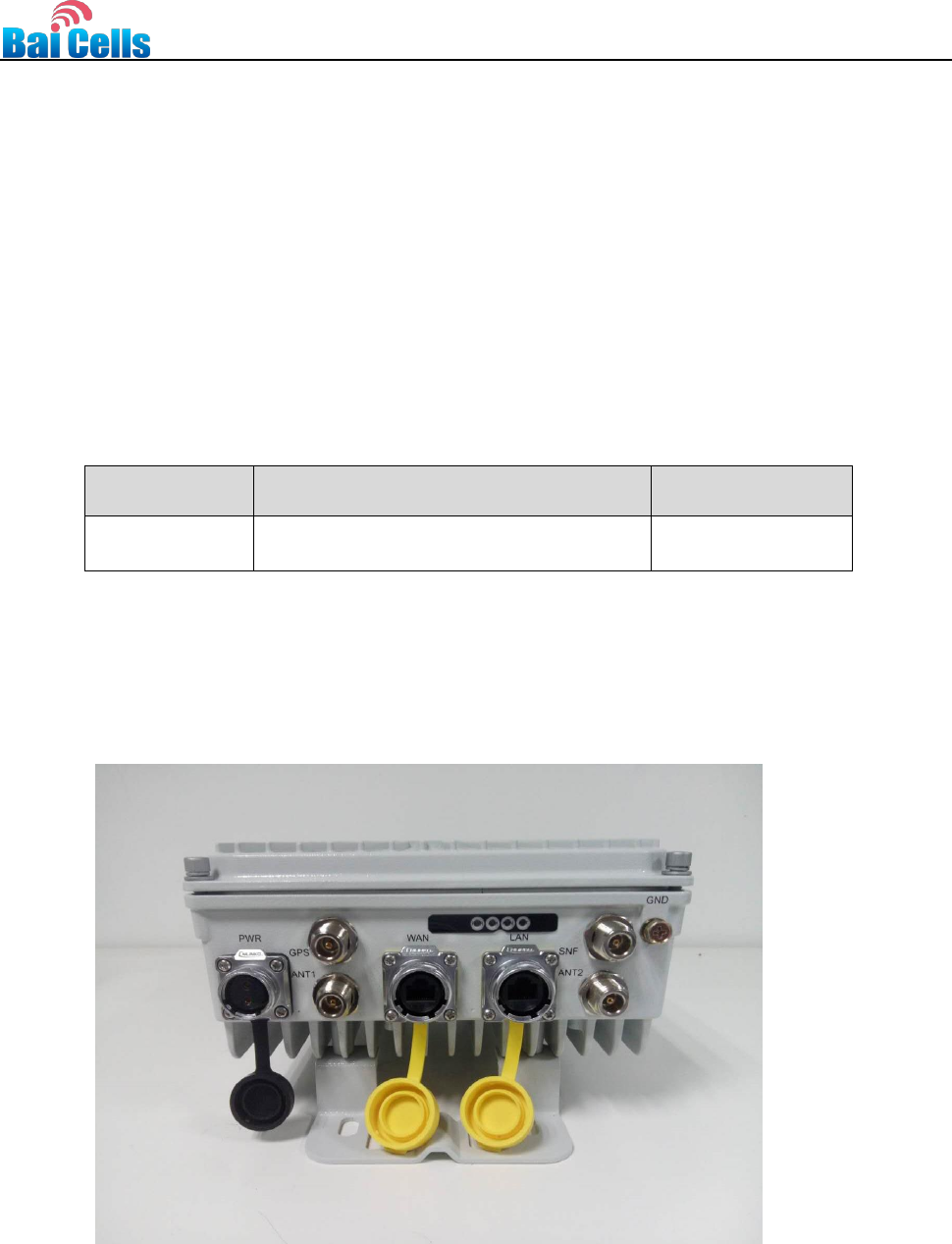
Interface specifications of mBS1100 outdoor base station are shown in Figure 1-2
Figure 1-2 Interfaces of mBS1100 outdoor base station
Interface
Description
PWR
Power interface:+48V DC (+42V~+58V)
LAN
Gigabit Ethernet debug port (not connected)
WAN
Gigabit Ethernet WAN port, used for external IP backbone
transmission network
GPS
External GPS antenna, N-Female screw(not connected)
ANT1
External antenna interface 1, N-Female screw
ANT2
External antenna interface 2, N-Female screw
SNF
External sniffer interface, N-Female screw
mBS1100 outdoor base station has 3 indicators. The indicator functions are defined and
described in Figure 1-3:
Figure 1-3 Function definition of mBS1100 outdoor base station indicator lights
Indicator
Color
Status
Meaning
PWR
Green light
On
Base station power-on
Off
No power input
RUN
Green light
On
Base station operation
Off
No power input or power fault
ALM
Red light
On
Hardware alarm, e.g. VSWR alarm
Off
No alarm
ACT
Green light
On
The transmitting channel works normally
(Standard: The community can build
channels or the transmitting channel
is open).
Off
The transmitting channel works
abnormally (for example, the transmitting
channel is closed).
2 Application Scenarios
2.1 Overview
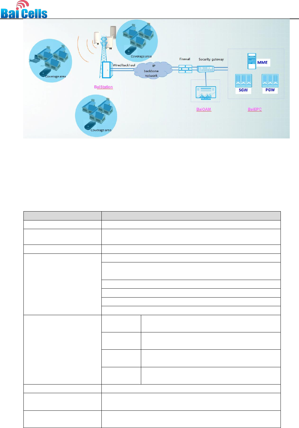
mBS1100 outdoor base stations mainly offer wireless broadband data services. mBS1100 can
support LTE-TDD wireless coverage and complete a variety of voice and data services.
Diagram 2-1 mBS1100 applied in outdoor wireless broadband solution
4
3 Technical Specifications
3.1 Hardware Specifications
Figure 3-1 Hardware specifications of mBS1100 outdoor base station
Item
Description
Working Mode
LTE TDD
Working Frequency
3650MHz~3700MHz
Working Bandwidth
10MHz/20MHz
External Interfaces
PWR interface: 1
WAN interface
Electrical Port : 1, RJ45
LAN interface: 1, RJ45
GPS interface: 1 N-Female
Antenna interface: 2 N-Female
SNF interface: 1 N-Female
Indicator
PWR
1, green light, Base station power status
indicator
RUN
1, green light, Base station operation status
indicator
ALM
1, red light, Base station alarm status
indicator
ACT
1, green light, transmitting channel status
indicator
Max Tx Power
33dBm
Receiving Sensitivity
1. 10MHz: -100dBm
2. 20MHz: -97dBm
Synchronization Mode
Support GPS, 1588V2, OTA (same or different
frequency)
5
MIMO
2*2MIMO
Backhaul Mode
Wired backhaul: Ethernet
Installation Method
Tower-mounted
Antenna
External high-gain antenna
Power Consumption
<65W
3.2 Software Specifications
Figure 3-2 Software specifications of mBS1100 outdoor base station
Item
Description
Technical
Standard
LTE TDD 3GPP Release 9
Business
Capability
32concurrent users, 96 connection users
Maximum
Throughput
DL: 110Mbps@20MHz UL: 20Mbps@20MHz
DL: 55Mbps@10MHz UL: 7Mbps@10MHz
Scheduling
Mode
Based on QoS scheduling
Modulation
Mode
Support: BPSK, QPSK, 16QAM, 64QAM
Voice Solution
Support CSFB, VoLTE, SRVCC
Traffic Offload
Support LIPA/SIPTO, which is Local IP Access, Selected IP
Traffic Offload for short(optional)
SON
Self-organizing network: support plug and play, automatic start,
optimization and configuration
RAN Sharing
Support
Network
Management
Interface
Support TR069 interface protocol
Northbound
Interface
Support: Web Service, Socket, FTP and other interface modes
Operation &
Maintenance
1. Support local maintenance
2. Support remote maintenance
3. Support online status management
4. Support performance statistics
5. Support failure management
6. Support configuration management
7. Support local or remote software upgrade and load
8. Diary
9. Support connectivity diagnosis
10. Support automatic start and configuration
11. Alarm reporting: support lower machine broken alarm, high
and low temperature alarm, weak wireless signal alarm report
6
3.3 Environment Specifications
Figure 3-3 Environment specifications of mBS1100 outdoor base station
Item
Description
Temperature
Working temperature: -35°C to 55°C
Storage temperature: -40°C to 70°C
Humidity
5%~100%
Temperature Change Rate
1°C /min
MTBF
≥150000 hours
MTTR
≤1 hour
4 Product List
Figure 4-1 List of mBS1100 outdoor base station products
Accessories
Quantity
Notes
mBS1100
1
Standard configuration, check
whether the frequency is consistent
with the required.
Warranty
1
Standard configuration
User Manual
1
Standard configuration
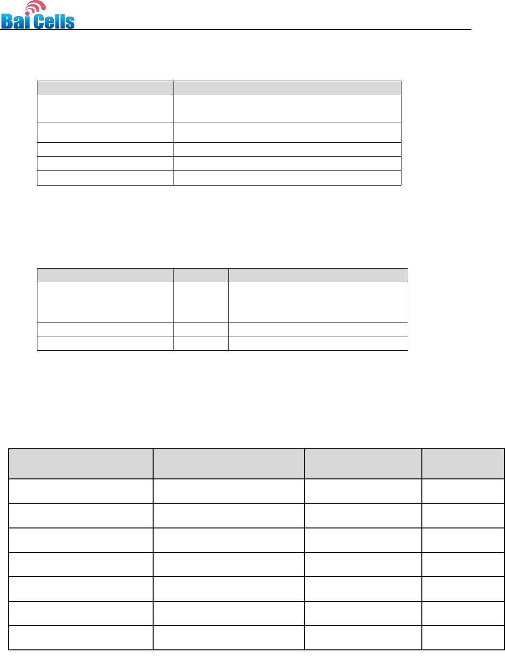
5 Antennas Information
Following is the list of antennas certified for use. Customers can choose according to use
environment of different antenna.
Antenna Type
Manufacturer
Model Number
Antenna Max
Gain(dBi)
External Planar Antenna Dual
Pole
Kenbotong Technology Co., Ltd.
KBT90DP16-3338AT0
16
External Planar Antenna Dual
Pole
Kenbotong Technology Co., Ltd.
KBT90DP14-3338AT0
14
External Planar Antenna Dual
Pole
Baicells Technologies Co., Ltd
ANT-3G11-R-65-EDT0
11
External Planar Antenna Dual
Pole
Baicells Technologies Co., Ltd
ANT-3G7-R-65-EDT0
7
External Omnidirectional
Antenna Single Pole
Kenbotong Technology Co., Ltd.
TQJ-3500AC10
10
External Omnidirectional
Antenna Single Pole
Kenbotong Technology Co., Ltd.
TQJ-3500AC7
7
External Omnidirectional
Antenna Single Pole
Kenbotong Technology Co., Ltd.
TQJ-3500AT6A
6
7
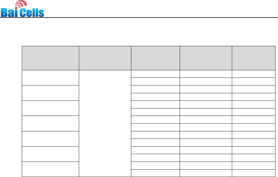
6 Maximum Output Power
The maximum output power can be set as follows:
Antenna Max
Gain (dBi)
10Log(Number
of antennas)
Channel BW
(MHz)
Max output
power
(dBm)
EIRP
(dBm)
16
3
10
21
40
20
24
43
14
10
23
40
20
26
43
11
10
26
40
20
29
43
7
10
30
40
20
33
43
10
10
27
40
20
30
43
7
10
30
40
20
33
43
6
10
30
39
20
33
42
FCC Compliance
This device complies with part 15 of the FCC Rules. Operation is subject to the following two
conditions: (1) This device may not cause harmful interference, and (2) this device must accept
any interference received, including interference that may cause undesired operation.
Any Changes or modifications not expressly approved by the party responsible for compliance
could void the user's authority to operate the equipment.
This equipment has been tested and found to comply with the limits for a Class B digital device,
pursuant to part 15 of the FCC Rules. These limits are designed to provide reasonable
protection against harmful interference in a residential installation. This equipment generates
uses and can radiate radio frequency energy and, if not installed and used in accordance with
the instructions, may cause harmful interference to radio communications. However, there is no
guarantee that interference will not occur in a particular installation. If this equipment does
cause harmful interference to radio or television reception, which can be determined by turning
the equipment off and on, the user is encouraged to try to correct the interference by one or
more of the following measures:
Reorient or relocate the receiving antenna.
Increase the separation between the equipment and receiver.
Connect the equipment into an outlet on a circuit different from that to which the receiver
is connected.
Consult the dealer or an experienced radio/TV technician for help.
Warning
This equipment complies with FCC radiation exposure limits set forth for an uncontrolled
environment. This equipment should be installed and operated with minimum distance 50 cm
between the radiator & your body.

8
IC Compliance
This device complies with Industry Canada licence-exempt RSS standard(s).
Operation is subject to the following two conditions: (1) This device may not cause interference
, and (2) This device must accept any interference, including interference that may cause undesi
red operation of the device.
Le présent appareil est conforme aux CNR d'Industrie Canada applicables aux appareils radio
exempts de licence. L'exploitation est autorisée aux deux conditions suivantes:
(1) l'appareil ne doit pas produire de brouillage, et
(2) l'utilisateur de l'appareil doit accepter tout brouillage radioélectrique subi, même si le
brouillage est susceptible d'en compromettre le fonctionnement.
The antenna(s) used for this transmitter must be installed to provide a separation distance of at
least 50 cm from all persons and must not be collocated or operating in conjunction with any
other antenna or transmitter, End-Users must be provided with transmitter operation conditions
for satisfying RF exposure compliance.