Barco N V ST150B01 Panel PC User Manual
Barco N.V. Panel PC
UserManual.wiki
>
Barco N V
>
ST150B01 User Manual
User manual
Navigation menu
Upload a User Manual
Namespaces
Wiki Guide
HTML
PDF
Info
Views
User Manual
Discussion / Help
Navigation
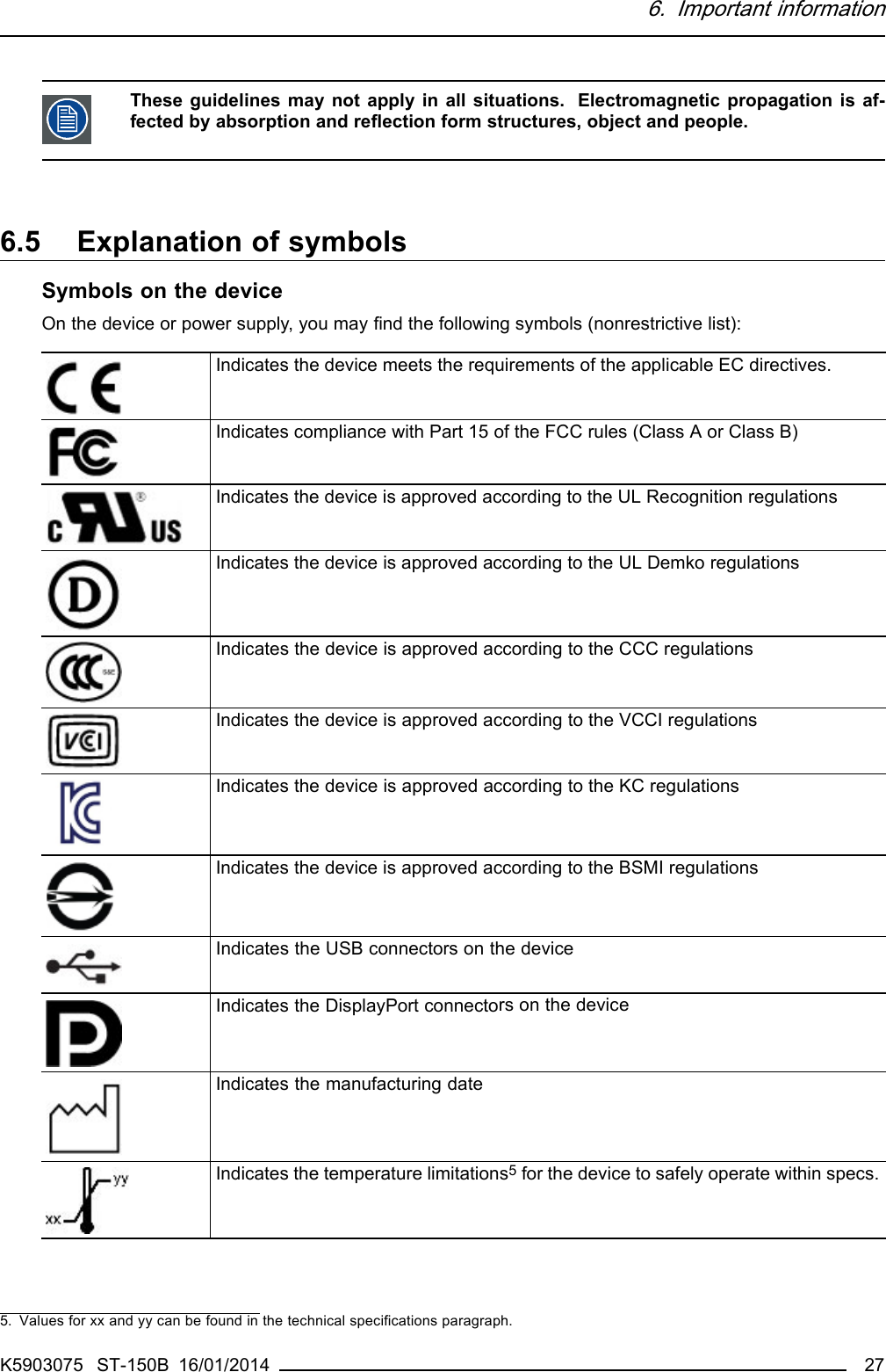
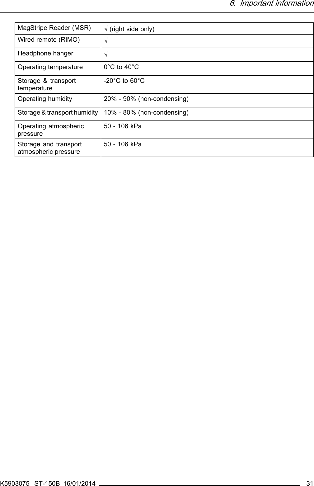
![6. Important informationBy participating in separate collection of batteries, you will help to ensure proper disposal and to preventpotential negative effects on the environment and human health.Turkey RoHS complianceTürkiye Cumhuriyeti: AEEE Yönetmeliğine Uygundur.[Republic of Turkey: In conformity with the WEEE Regulation]中国大陆RoHSChinese Mainland RoHS根据中国大陆《电子信息产品污染控制管理办法》(也称为中国大陆RoHS), 以下部分列出了Barco产品中可能包含的有毒和/或有害物质的名称和含量。中国大陆RoHS指令包含在中国信息产业部MCV标准:“电子信息产品中有毒物质的限量要求”中。According to the “China Administration on Control of Pollution Caused by Electronic Information Products”(Also called RoHS of Chinese Mainland), the table below lists the names and contents of toxic and/orhazardous substances that Barco’s product may contain. The RoHS of Chinese Mainland is included inthe MCV standard of the Ministry of Information Industry of China, in the section “Limit Requirements oftoxic substances in Electronic Information Products”.零件项目(名称)Component name有毒有害物质或元素Hazardous substances and elements铅Pb汞Hg镉Cd六价铬Cr6+多溴联苯PBB多溴二苯醚PBDE印制电路配件Printed Circuit Assembliesxooo oo外接电(线)缆External Cablesxooo oo內部线路Internal wiringoo oo oo塑胶外壳Plastic enclosureoo oo oo电源供应器Power Supply Unitxooo oo风扇Fanoo oo oo文件说明书Paper Manualsoo oo oo光盘说明书CD manualoo oo ooO: 表示该有毒有害物质在该部件所有均质材料中的含量均在 SJ/T 11363-2006 标准规定的限量要求以下.O: Indicates that this toxic or hazardous substance contained in all of the homogeneous materials forthis part is below the limit requirement in SJ/T11363-2006.X: 表示该有毒有害物质至少在该部件的某一均质材料中的含量超出 SJ/T 11363-2006 标准规定的限量要求.X: Indicates that this toxic or hazardous substance contained in at least one of the homogeneousmaterials used for this part is above the limit requirement in SJ/T11363-200622 K5903075 ST-150B 16/01/2014](https://usermanual.wiki/Barco-N-V/ST150B01/User-Guide-2172792-Page-24.png)