Baron Services XDD-1000C C-BAND DOPPLER WEATHER RADAR User Manual 4017 B FinalRevA
Baron Services Inc C-BAND DOPPLER WEATHER RADAR 4017 B FinalRevA
Contents
- 1. Modulator Manual
- 2. Users Manual Part 1
- 3. Users Manual Part 2
- 4. Users Manual Part 3
- 5. S10 OPERATION AND MAINTENANCE MANUAL
- 6. S10 FAST TRAC MILLENIUM USERS GUIDE
- 7. S10 TECHNICAL MANUAL
- 8. S10 RECEIVER AND PROCESSOR USERS MANUAL PART 1
- 9. S10 RECEIVER AND PROCESSOR USERS MANUAL PART 2
- 10. S10 RECEIVER AND PROCESSOR USERS MANUAL PART 3
S10 OPERATION AND MAINTENANCE MANUAL

OPERATION AND MAINTENANCE
MANUAL
ELEVATION OVER AZIMUTH
POSITIONER
AL-4017-1EBS-B
For Baron Services Radars:
XDD-350C ®
VHDD-350C ™
HDD-350C ™
HDD-250C ™
VHDD-1000C ™
BARON RADAR SERVICES, L.L.C.
4930 Research Drive
Huntsville, AL 35805
PHONE: 256.881.8811 FAX: 256.881.8283
S10

1-2
Table of Revisions
REV DATE DESCRIPTION BY
A 10/9/03 Added VHDD-1000C to front cover CK
i
TABLE OF CONTENTS
SECTION 1 DESCRIPTIONS........................................................................................................... 1
1.1 General Description...................................................................................................................... 1
1.2 Technical Description................................................................................................................... 1
1.3 Specifications ................................................................................................................................ 1
1.4 Mechanical Sub-Assemblies......................................................................................................... 1
1.4.1 Elevation Unit..........................................................................................................................1
1.4.2 Azimuth Unit...........................................................................................................................2
1.5 Electromechanical Sub-Assemblies.............................................................................................. 2
1.5.1 Limit Switches.........................................................................................................................2
SECTION 2 INSTALLATION & OPERATION................................................................................ 4
2.1 General.......................................................................................................................................... 4
2.2 Positioner Installation................................................................................................................... 4
2.3 Antenna Installation..................................................................................................................... 4
2.4 Operation Instructions ................................................................................................................. 5
SECTION 3 MAINTENANCE ........................................................................................................... 7
3.1 General.......................................................................................................................................... 7
3.2 Cleaning ........................................................................................................................................ 7
3.2.1 Exterior Cleaning.....................................................................................................................7
3.2.2 Interior Cleaning......................................................................................................................8
3.3 Lubrication ................................................................................................................................... 8
3.3.1 Periodicity ...............................................................................................................................8
3.3.2 2000 Hour or 2-Month Lubrication..........................................................................................8
3.3.3 17000 Hour or 2-year Lubrication............................................................................................8
3.3 Electromechanical Components................................................................................................. 11
3.3.2 General..................................................................................................................................11
3.3.3 Limit Switches Maintenance..................................................................................................11
3.3.4 Limit Switch Adjustment Procedure (see Figure 1) ................................................................11
ii
3.4 Timing Belt Installation And Adjustment ................................................................................. 13
3.4.1 Belt Tension (refer to Figure 2) .............................................................................................13
3.4.2 Sprocket Alignment ...............................................................................................................15
3.4.3 Belt Handling.........................................................................................................................15
3.4.4 Belt Storage ...........................................................................................................................15
3.5 Replacement of Azimuth Motor Assembly ................................................................................ 15
3.5.1 Removal of Azimuth Motor Assembly...................................................................................15
3.5.2 Installation of Azimuth Motor Assembly ...............................................................................17
SECTION 4 STORAGE AND PREPARATION FOR USE.......................................................... 19
SECTION 5 REPLACEMENT PARTS .......................................................................................... 20
5.1 PARTS LIST............................................................................................................................... 20
5.1.1 GENERAL............................................................................................................................20
5.1.2 ITEM NUMBER (ITEM No.)................................................................................................20
5.1.3 DESCRIPTION .....................................................................................................................20
5.1.4 PART NUMBER (PART No.) ...............................................................................................20
5.1.5 QUANTITY (QTY)...............................................................................................................20
5.1.6 ORDERING INFORMATION FOR PARTS.........................................................................21
APPENDIX............................................................................................................................................. 22
LIST OF TABLE AND FIGURES
TABLE 1. AL-4017-1EBS-B SPECIFICATIONS.................................................................................. 3
TABLE 2. RECOMMENDED LUBRICANTS AND LUBRICATION INTERVALS....................... 10
FIGURE 1. LIMIT SWITCH ASSEMBLY......................................................................................... 12
FIGURE 2: RECOMMENDED BELT TENTION............................................................................... 14
FIGURE 3. AL-4017-1EBS-B POSITIONER ASSEMBLY............................................................... 18
TABLE 3. AL-4017-1EBS-B Parts List................................................................................................. 21
1
SECTION 1 DESCRIPTIONS
1.1 General Description
The Positioner AL-4017-1EBS-B is comprised of two modified ORBIT
Standard AL-760's.
The modifications were performed according to Baron Service’s
specifications concerning speed, acceleration, antenna adapter and
environmental conditions (see Table 1).
1.2 Technical Description
The AL-4017-1EBS-B Elevation-over-Azimuth Positioner has two main
units: Elevation and Azimuth. All parts are submitted to high-stress tests
to ensure reliability and avoid downtime.
1.3 Specifications
The specifications of the AL-4017-1EBS-B EL/AZ Positioner are listed in
Table 1.
1.4 Mechanical Sub-Assemblies
1.4.1 Elevation Unit
The Elevation Unit, mounted on the turntable of the Azimuth Unit, turns
the upper turntable through the vertical plane. The mechanism of the
Elevation Unit is as follows: A DC motor drives a worm gear through a
timing belt. The worm gear drives an internal gear, an integral part of a
ball race type slewing bearing assembly, which is designed and produced
according to very high standards and specifications. The internal gear is
the linking element between the Azimuth and Elevation Units.

2
1.4.2 Azimuth Unit
The Azimuth Unit turns the Positioner through the horizontal plane. It is
designed to handle vertical and radial loads. The mechanism of the
Azimuth Unit is as follows: A DC motor drives a reduction worm gear
through a timing belt. The pinion on the reduction gear drives an internal
gear, which is an integral part of a slewing bearing assembly. The internal
gear drives the turntable, which carries the Elevation unit.
1.5 Electromechanical Sub-Assemblies
1.5.1 Limit Switches
The limit switches are designed to coordinate the rotation of the El axis.
The limit switches are of the electric rotary cam type. Each limit switch
assembly has two cams, one for UP and one for DOWN. The limit
switches are normally open.

3
TABLE 1. AL-4017-1EBS-B SPECIFICATIONS
PARAMETERS UNIT VALUE
AZIMUTH BEARING MOMENT
CAPACITY ft-lbs 3000
VERTICAL LOAD lbs 800
DELIVERED TORQUE Azimuth ft-lbs 170
Elevation ft-lbs 170
WITHSTAND TORQUE Azimuth ft-lbs 500
Elevation ft-lbs 500
NOMINAL SPEED Azimuth deg/sec. 36
Elevation deg/sec. 36
DATA TAKE-OFF ACCURACY Azimuth deg. ±0.07
Elevation deg. ±0.07
MAXIMUM BACKLASH Azimuth deg. 0.05
Elevation deg. 0.05
ELEVATION LIMIT-TO-LIMIT TRAVEL deg. -2 to +182
AZIMUTH TRAVEL deg Continuous
OPERATING TEMPERATURE °C -20 to +55
WEIGHT lbs 950
Note:
When slip rings and/or rotary joints are used, limit switches are disabled.

4
SECTION 2 INSTALLATION & OPERATION
2.1 General
The AL-4017-1EBS-B Elevation over Azimuth positioner is shipped as a
ready-mounted unit (pedestal assembled on base riser).
Unpack the system and examine it for any damage that may have
occurred in transit. Check connectors, units, the base, and the body itself.
The site on which the Positioner is to be placed must be adequate to
support its weight. Unless otherwise stated, Positioners are dispatched
with the upper turntable in the zero position and locked on zero.
2.2 Positioner Installation
Using an adequate hoisting device and lifting eye, place the Positioner on
the designed location and clamp it with 3/4" UNC bolts and torque to ≈100
ft-lbs.
2.3 Antenna Installation
CAUTION
To prevent injury to personnel and damage to equipment, always
make sure that the SAFE/OPERATE switch on the connector panel is
set to SAFE, prior to antenna installation on Positioner.
a. The antenna should be fastened to the upper turntable using the
specially designed antenna support. When mounting the antenna it is
important to consider the Positioner's bending moment rating. The
weight of an antenna assembly, wind, and/or ice-formation may all
subject a Positioner, located in the open, to a bending moment.
When approaching the Positioner's maximum rating, caution should

5
be exercised since the additional moment load on the antenna from
wind force may be enough to exceed the maximum load rating.
b. Inertia loading must also be considered since, during both
acceleration and deceleration, the torque load on the drive train
mechanism increases. Inertia overload causes slow starting and
commensurate increase in motor current to compensate for the
excessive drive torque required. Faltering, vibration, and exceeding
of the torque rating on deceleration may all result from inertia
overload, causing excessive gear wear and possible tooth breakage.
CAUTION
To avoid damage to the Positioner drive train from inertial overload,
it is vital to apply speed changes slowly whenever an overload is
suspected. This is because inertial torque effects are proportional
to the square of the turntable speed.
2.4 Operation Instructions
CAUTION
Prior to any operation of the Positioner, make sure that no person
or equipment is inside the Positioner rotation area.
a. Set the "SAFE/OPERATE" switch to "OPERATE" position.
b. Set Power Switch on the Controller to the "ON" position - "ON" lamp
will illuminate. The positioner will perform a self-test by slewing in
both azimuth and elevation.
c. Upon completion of the self-test, choose between "LOCAL" operation
(operation by means of the Controller) or "REMOTE" operation
(operation by means of the Computer) by setting the Controller to the
desired mode of operation, using the LOCAL/REMOTE switch. The
Positioner and System are now ready to operate.

6
d. To operate the System, refer to the applicable Controller Operation
Manual.
WARNING
TO PREVENT INJURY TO MAINTENANCE PERSONNEL
OR DAMAGE TO EQUIPMENT, ALWAYS VERIFY THAT
NO EXTERNAL VOLTAGE IS SUPPLIED TO THE
POSITIONER AND THAT THE SAFE/OPERATE SWITCH
IS IN THE SAFE POSITION, PRIOR TO PERFORMING
ANY MAINTENANCE WORK ON THE POSITIONER.
IF POWER MUST BE APPLIED FOR TEST PURPOSES,
TAKE ALL THE STEPS THAT ARE NECESSARY IN
ORDER TO AVOID INJURIES AS A RESULT OF
ELECTRICAL SHOCKS AND MOVEMENT OF
MECHANICAL UNITS.

7
SECTION 3 MAINTENANCE
3.1 General
This chapter provides information necessary for maintaining the AL-4017-
1EBS-B Elevation-over-Azimuth Positioner series in optimal operating
condition.
Note
When performing maintenance operations, the internal components
such as motors, electrical devices, wires, connectors, and
mechanical elements, should be visually inspected.
3.2 Cleaning
The Positioner should be cleaned as often as dictated by the operating
conditions. It should be kept free of dust, moisture and grease. If available,
use a vacuum cleaner to remove all accumulated dust from the interior
and exterior of the Positioner.
3.2.1 Exterior Cleaning
Loose dust can accumulate on the exterior surface of the positioner.
Remove this dust with a soft cloth or a soft bristle brush. A cloth saturated
with cleaning solvent may also be used.
8
3.2.2 Interior Cleaning
Loose dust in the Positioner interior must be removed due to its electrical
conductivity under humid conditions. The recommended method is to use
a vacuum cleaner. Remove any remaining dirt with a soft bristle brush or a
cloth soaked in cleaning solvent. A cotton-tipped applicator is useful for
cleaning narrow spaces.
3.3 Lubrication
This section includes access information, periodicity, and lubrication
procedures.
3.3.1 Periodicity
Lubrication of the Positioner should be performed periodically, per the
intervals listed in Table 2.
3.3.2 2,000 Hour or 2-Month Lubrication
3.3.2.1 Slewing Bearing Lubrication
a. Inject 2cc of grease (see Table 2), through the grease fitting,
every 60° of the Azimuth turntable rotation. For Elevation, inject
grease at the end of the travel, in each direction.
b. When operating under very hot or dry environmental conditions,
inspect and inject grease more frequently.
3.3.3 17,000 Hour or 2-year Lubrication
3.3.3.1 Ring-Gear Lubrication
a. Using a 5/32-inch Allen wrench, loosen the two screws fastening
the primary limit switch assembly to the body.

9
b. Through the limit switch hole in the body apply a thin layer of
grease on the gear teeth. Then, rotate the turntable a small
amount and again apply a thin layer of grease on the gear teeth.
Continue this rotating and greasing process until the turntable
completes one full revolution.
c. Remount the limit switch after rotating the turntable to its previous
position.
Note
To achieve the previous position, verify that the angle that is
displayed on the controller's console is the same angle that was
displayed before the removing of the limit switch assembly.

10
TABLE 2. RECOMMENDED LUBRICANTS AND LUBRICATION INTERVALS
Item Lubricant Type Manufacturer Interval
Large ring Grease Molykote Dow Corning 17,000 hours of
gear 165 LT GmbH operation or
2 years
Bearings Grease Isoflex Kluber 1,500 hours of
LDS 18 operation or
Special A 2 months
Reduction Grease Shell Tivella Shell Oil Co. During
gear Compound A overhaul
Note: If the required Lubricants, as described in the above table, are not
available in your area; please contact your Baron Services
Representative for assistance.

11
3.3 Electromechanical Components
3.3.2 General
Common components, such as encoders and limit switches, do not
usually require special servicing; such components may be serviced
during general overhaul. Maintenance information for the limit
switches is given in the following pages.
3.3.3 Limit Switches Maintenance
The limit switches are factory adjusted prior to shipment. However,
when Positioner readjustment or change of rotation limits is
necessary, the limit switches must be readjusted.
CAUTION
To avoid damage to the internal cables (connecting the Azimuth
Unit to the Elevation Unit), verify that the new adjusted turning
range does not exceed the specified range.
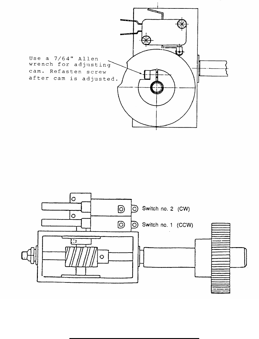
3.3.4 Limit Switch Adjustment Procedure (see Figure 1)
a. Turn Positioner axis to the desired limit angle (CW or CCW).
b. Gain access to limit switch assembly.
c. Using a 7/64" Allen wrench, release the appropriate limit
switch cam fastening screw (S1 for CCW and S2 for CW).
d. Rotate the appropriate switch cam until Positioner operation is
inhibited in the desired direction and retighten the cam screw.
e. Turn the Positioner in the opposite direction and then return it
in the limit direction. Verify that Positioner operation is stopped
at the desired angle.
12
FIGURE 1. LIMIT SWITCH ASSEMBLY
13
3.4 Timing Belt Installation And Adjustment
The Timing belt should be installed with a snug fit, neither too tight nor too
loose. The belt's positive grip eliminates the need for initial tension.
Consequently, a belt, when installed with a snug fit (that is, not too tight),
assures longer life, less wear on bearings and quieter operation.
Preloading, often the cause of premature failure, is not necessary.
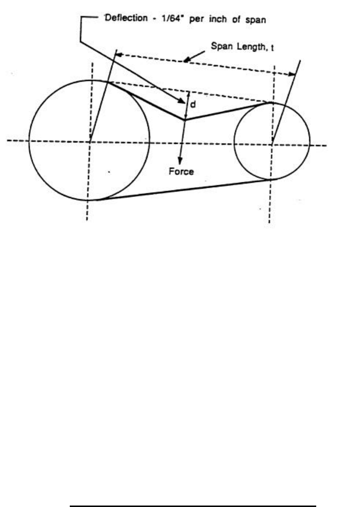
3.4.1 Belt Tension (refer to Figure 2)
When torque is unusually high, a loose belt, on starting, may "jump teeth".
In such a case, the tension should be increased gradually until satisfactory
operation is attained.
When the safety switch is in the OPERATE position, run the polarizer so
that the top of the belt is slack and return the safety switch to the SAFE
position. The application of a force (f) of 1.3 lbs (0.59 Kg) at the midpoint
of the slack span, between the two pulleys, shall result in a deflection (d)
of 0.21 inch (5.4mm).
If the force (f) required to obtain the specified deflection (d) is less than
specified, the belt is too loose. If the force (f) required to obtain the
specified deflection (d) is greater than that specified, the belt is too tight.
Adjust the motor position until the specified force and deflection
measurements are obtained.
14
FIGURE 2: RECOMMENDED BELT TENTION
d = 0.21 inch (5
.4 mm)
f = 1.3 lbs (0.59 Kg.)
15
3.4.2 Sprocket Alignment
Misalignment of drive results in unequal tension and extreme edge wear.
Consequently, sprocket alignment should be verified by means of a
straight-edge and shafts checked to assure parallelism. On a long-center
drive, due to the belt's tendency to run against one flange of the drive
sprocket, it is often advisable to offset the driven sprocket slightly to
compensate for this effect.
3.4.3 Belt Handling
On installation, the belt should never be forced or pried over the sprocket
flange. Reduction of center distance usually permits the belt to slide into
the sprocket easily. Otherwise, one or both sprockets must be removed.
3.4.4 Belt Storage
To assure smooth operation and to prevent premature failure, belts in
storage should be protected against sharp bending or creasing. Avoid
subjecting belts to extreme heat, low temperature or high humidity.
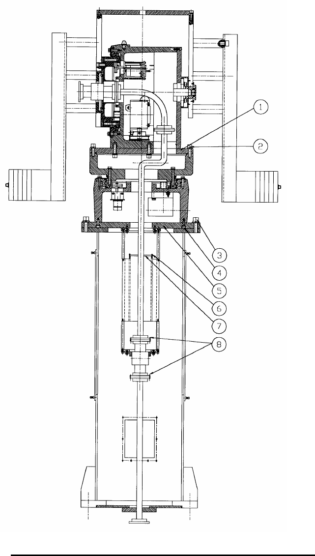
3.5 Replacement of Azimuth Motor Assembly
3.5.1 Removal of Azimuth Motor Assembly
Use the following procedure to remove the Azimuth Motor Assembly
(Refer to Figure 3):
a. Rotate the Elevation Axis until it is at the 90 deg. vertical position;
i.e. pointing straight up.

16
b. Set the SAFE/OPERATE switch to the SAFE position.
c. Remove the antenna, counterweights, and the two arms located on
the Elevation Axis.
d. Remove the four screws on each flange (8) and the screws (3)
securing the Positioner to the base riser.
e. Detach the connectors MOL1 thru MOL4, located in the base riser.
f. Lift the Positioner off of the base riser and place it on a secure
working surface; e.g. a table.
g. Support the Positioner in a level position.
h. Remove screws (6), cut the tie wraps located on the waveguide and
remove the parts (7) from the Slip-Ring.
i. Remove the screws (4) securing the lower plate (5) to the Azimuth
unit.
j. Separate the lower plate (5) from the Azimuth unit.
Note:
The length of the wiring harness between the slip-ring and the
elevation unit is long enough to allow the plate (5) to be moved
away from the Azimuth unit by a distance of approximately one foot.
k. Remove the four screws securing the motor bracket to the azimuth
positioner body.
l. Using a "heat gun", remove the LOCKTITE No. 241 epoxy from the
four screws securing the motor to the bracket.
m. Remove the four screws attaching the motor to the bracket.
n. Carefully, remove the motor from the bracket.

17
o. Remove the pulley from the motor shaft and retain it for installation
on the shaft of the new motor.
3.5.2 Installation of Azimuth Motor Assembly
For new Azimuth Motor installation, follow the removal procedure in
paragraph 3.6.1 in a logical reverse sequence using the following notes:
Notes:
1) When the lower plate (5) is assembled to the Azimuth unit, be sure
that the extra length of the wire harness between the slip-ring and
the elevation unit is inserted in part (1). Loose wiring inside the
Azimuth unit should be secured to the waveguide by means of tie
wraps.
2) When assembling the positioner, verify that the waveguide and
lower plate (5) O-ring gaskets are in good condition and are
installed in their proper locations. Verify that all screws are securely
fastened.
3) After the installation procedure is completed, the new motor and gear
sprockets must be aligned according to para. 3.5.2; and the tension of
the belt between the new motor and the gear must be adjusted according
to para. 3.5.1.
18
FIGURE 3. AL-4017-1EBS-B POSITIONER ASSEMBLY
19
SECTION 4 STORAGE AND PREPARATION FOR USE
Store the Positioner in a closed place, protected from dust and rain.
Once a month, rotate the Positioner at each axis, three times from limit to limit.
Before using the Positioner after a long storage period, re-lubricate the bearings.
Refer to lubrication instructions.
20
SECTION 5 REPLACEMENT PARTS
5.1 PARTS LIST
5.1.1 GENERAL
The various parts used in the AL-4017-1EBS Positioner are listed in the
following parts list table. The purpose of this part list is for identification,
requisition, and issuance of spare or replacement parts. For part replacement,
use only part numbers specified in this parts list.
The parts list table is divided into four columns, which are described in the
following paragraphs.
5.1.2 ITEM NUMBER (ITEM No.)
The first column in the parts list table contains item numbers, assigned in
sequence.
5.1.3 DESCRIPTION
The second column contains brief descriptive information for each part.
5.1.4 PART NUMBER (PART No.)
The third column lists manufacturer's part numbers.
5.1.5 QUANTITY (QTY)
The fifth column lists quantity of each item used in the Positioner.

21
5.1.6 ORDERING INFORMATION FOR PARTS
When ordering spare or replacement parts, state the full description of part, part
number, and the desired quantity.
TABLE 3. AL-4017-1EBS-B Parts List
Item
No.
Description Part No. Qty.
1. Az. Motor Assy. BS-104453 1
2. El. Motor Assy. BS-104452 1
3. Encoder BS-104455 2
4. Reduction Gear BS-104151 2
5. Pulley (Az/El) (Motor) BS-104482 2
6. Belt BS-104456 2
7. Pulley (Az/El) (Gear) BS-104483 2
8. Slewing Bearing BS-104107 2
9. Az Power Amp. BS-104134 1
22
APPENDIX
AL-4017-1EBS-B
INTERFACE CONTROL DRAWING (ICD) - Dwg. No. 19-0342
WIRING DIAGRAM - Dwg. No. 19-0361-1/2
SYSTEM LAYOUT - Dwg. No. 19-0589

OPERATION AND MAINTENANCE
MANUAL
AL-1642-3JB
Two-Axis Controller
With Built-In Servo Amplifier
For Baron Services Radars:
XDD-350C ™
XDD-300X ®
VHDD-350C ™
VHDD-1000C™
BARON SERVICES, INC.
4930 Research Drive
Huntsville, AL 35805
PHONE: 256.881.8811 FAX: 256.881.8283

Table of Revisions
REV DATE DESCRIPTION BY
A 10/9/03 Added VHDD-1000C to front cover CK
TABLE OF CONTENTS
SECTION 1 INTRODUCTION .................................................................................... 1
SECTION 2 FRONT PANEL OPERATION............................................................... 2
2.1 Front Panel Keypad................................................................................................ 2
2.2 Front Panel Joystick and Fine/Coarse Switch ....................................................... 3
2.3 Front Panel Power Switch...................................................................................... 3
2.4 Front Panel Display ................................................................................................ 4
SECTION 3 REAR PANEL CONFIGURATION ....................................................... 5
3.1 Power Selection, Input, and Fuses.......................................................................... 5
3.2 Motor Fuses............................................................................................................. 5
3.3 Positioner Connectors ............................................................................................. 6
3.3.1 Encoder IN/OUT (J3).............................................................................................6
3.3.2 Motor Power and Limits (J5)..................................................................................6
3.4 Communication Connectors ................................................................................... 7
SECTION 4 REMOTE OPERATION.......................................................................... 8
4.1 Modes of Operation ................................................................................................ 8
4.1.1 Standby..................................................................................................................8
4.1.2 Point ......................................................................................................................9
4.1.2.1 Single Point Commands .........................................................................................9
4.1.2.2 Repeated Point Commands (Track Mode)..............................................................9
4.1.3 Home ...................................................................................................................10
4.1.4 Slew.....................................................................................................................10
4.1.5 Calibrate ..............................................................................................................10
4.1.6 Raster Scan Mode ................................................................................................11
4.1.6.1 Azimuth Raster Scan Mode ..................................................................................12
4.1.6.2 Elevation Raster Scan Mode.................................................................................13
4.2 Serial Protocol - Data Link Level......................................................................... 14
4.3 Serial Protocol - Commands from Host Computer to ACU................................ 15
4.4 Serial Protocol - Replies from ACU to Host......................................................... 16
4.5 Command codes and parameters ......................................................................... 18
4.5.1 General comments................................................................................................18
4.5.2 Parameter Limits..................................................................................................18
4.5.3 Alphabetical command listing..............................................................................19
SECTION 5 TROUBLESHOOTING......................................................................... 28
SECTION 6 MAINTENANCE.................................................................................... 30
6.1 Amplifier Adjustment........................................................................................... 30
6.2 Voltage Tests ......................................................................................................... 30
APPENDIX A................................................................................................................... 31
APPENDIX B .................................................................................................................. 42
1 INTRODUCTION
The AL-1642-3JB is a higher power version of the AL-1613-3JB
Antenna Control Unit (ACU) for controlling a two-axis elevation-
over-azimuth positioner. A front panel provides manual control of
the antenna from the controller through a joystick, a set of
pushbuttons, and two 8-character LED displays, one for each axis.
Two RS-232 serial links are provided. One link provides for
remote control and parameter tuning. Modes of operation in remote
control include Go-to-Point, Slew, Raster Scan, Go-to-Home
Position, Standby, and Calibrate. The second link provides
azimuth and elevation position continuously.
Go-to-Point mode includes an extrapolation algorithm designed to
allow the controller to closely follow a trajectory sent over the
serial link. This algorithm is used automatically when point
commands are received at a sufficiently rapid rate. Most important
control gains and parameters may be tuned over the serial link and
stored in non-volatile memory.
The AL-1642-3JB is packaged in a 4U height 19"-wide rack-
mount box which includes DC power supplies, a CPU card, an I/O
card, two amplifiers for the DC motors, and the front panel card.
The CPU card, based on the Intel 80960KB RISC processor,
performs closed loop control of the axis positions and manages the
serial protocol and front panel. The I/O card contains inputs for
encoders to read axis positions, digital inputs for limit switches,
digital outputs for the drive enable and analog outputs for the
current references for the motors. It also contains the serial
communications chip and drivers for the RS-232 communication
link. The front panel card provides interfaces for the joystick, the
pushbuttons, and the 8-character displays for reading the angles.
The amplifiers provide closed loop velocity control of the motors,
as well as protective functions, such as constant current limiting,
peak current limiting, clockwise motion limiting, and
counterclockwise motion limiting.
2 FRONT PANEL OPERATION
The front panel is shown in Figure B-3. It consists of a joystick, a
fine/coarse switch, two 8-character displays, two LEDs, three
pushbuttons, and an on/off power switch.
When the AL-1642-3JB is first powered on, the unit will be in
REMOTE mode, permitting remote operation without access to the
Controller.
2.1 Front Panel Keypad
The front panel contains 3 pushbuttons with functions as follows:
REM/LOC - Toggle between remote and local modes. In remote
mode, the other front panel controls are inactive and all control is
by commands over the serial communications link. In local mode,
commands over the serial link which could move the positioner are
not accepted. This includes axis mode commands and pointing
commands. Position is controlled instead through the joystick and
other front panel switches. The REM/LOC switch also places the
controller in Standby mode whenever it is pressed, bringing the
positioner to zero velocity.
CAL - This function is required because the position measurement
is based on incremental encoders. It finds the mechanical zero
point of the positioner and resets the angle displays accordingly.
A detailed explanation of the calibration sequence and the
parameters that affect it is given in section 4.1.5 below.
OFFSET - Set azimuth offset so that the present angle will be zero.
If the positioner is moving, it is first commanded to zero velocity.
If the positioner is calibrated, the offset is saved to non-volatile
memory.
2.2 Front Panel Joystick and Fine/Coarse Switch
The joystick is a dual axis unit with a spring return to zero. It allows
controlled movement of both axes at a wide range of velocities when in
MANUAL mode. Movement of the joystick UP or DOWN causes elevation
motion in the CW or CCW direction respectively. Movement to the right or
left causes CW or CCW azimuth motion.
The joystick is a very sensitive control unit. An excessive amount of force is
not required in order to move the stick. Extreme force can cause damage to
the joystick.
The velocity varies with the amount the joystick is moved from its center
position. A central region of approximately ±10% of the joystick's total travel
range gives zero velocity. The next ±40% gives a velocity range which
increases slowly at first and then increases rapidly. The last ±50% of the travel
provides a velocity which increases at a linear rate with respect to joystick
position. In all ranges, a deadband of ±2.5% keeps the velocity constant until a
motion of at least 2.5% of the stroke length is made.
A front panel velocity parameter, which may also be adjusted via the
communications link, is the maximum velocity when the FINE/COARSE
switch is set to COARSE. With the FINE/COARSE switch set to FINE, the
maximum velocity is reduced by a factor of 10.
With a typical maximum velocity of 36 deg/sec., velocities of about 0.3
deg/sec. to 36 deg/sec. are possible in COARSE mode, and 0.03 deg/sec. to
3.6 deg/sec. in FINE mode.
Zero-adjust levers are provided for each axis of the joystick. If a small
velocity exists, with the joystick at the center position, this may be nulled by
adjusting these levers.
2.3 Front Panel Power Switch
This switch will switch the main power, which may be either 115 VAC or 230
VAC, depending on settings of rear panel switches described below. The
switch will be illuminated when 230 VAC power is in use and the switch is in
the ON position.
2.4 Front Panel Display
Azimuth and Elevation angles are displayed on the front panel using 8-
character LED displays. Six of the characters provide the angle reading to a
precision of 0.001 degree. The 7th character is for the sign of the angle, and
the 8th character provides limit information.
A rapidly blinking display (4-Hz) indicates that the axis has not completed its
calibration cycle.
A slowly blinking display (2-Hz), along with a letter in the limit character,
indicates that a limit switch has been tripped, stopping the positioner motion.
Motion is then permitted only in the direction away from the limit.
L (left) indicates CCW azimuth limit (decreasing angle).
R (right) indicates CW azimuth limit (increasing angle).
U (up) indicates CW elevation limit, and D (down) indicates CCW
elevation limit.
A slowly blinking letter in the limit character, with the rest of the display not
blinking, indicates that the positioner has reached the software limit maximum
or minimum angle. These limit angles may be adjusted by commands over
the serial communication link.
The angle display may be changed by commands CCA and CCE on the serial
communications link. The precision may be set to 0.1, 0.01, or 0.001 degree.
The format may be set to 0-359.999 or +/-780 degrees. If desired, the limit
character may be displayed (without blinking) to indicate cable wrap (when
the angle is outside the center +/-180 degree area). This cable wrap feature is
particularly useful with a 0-359.999 degree display format.
3 REAR PANEL CONFIGURATION
The rear panel is shown in Figure B-4. It contains a power select area, power
input, fuses, a connector for the cable to the positioner, two communications
connectors, and a chassis ground connector.
3.1 Power Selection, Input, and Fuses
Power input is through the power connector J1.
The switch labeled "MAINS SELECT" has two positions, 115 VAC and 230
VAC.
The "MAINS SELECT" switch must be set to the proper
input voltage. If this is not done, damage may result to
the internal power supply used to provide DC current for
the positioner motors and the electronic circuitry.
Fuse F1 is for the AC input. Recommended fuses to be used are 4 Amp
"slow-blow" type for 230 VAC input, 8 Amp "slow-blow" type for 115 VAC.
High breaking capacity fuse (greater than 500 Amps) should be used.
3.2 Motor Fuses
Fuse F2 protects the azimuth motor and fuse F3 protects the elevation motor.
Current limit protection already exists in the amplifiers and is set to 5 Amps
continuous and 10 Amps for peaks of less than 2 seconds. This will protect
the motors from thermal overheating for ambient temperatures up to about
45°C. "Slow-blow" type fuses of 10 Amps are recommended as further
protection.
3.3 Positioner Connectors
The positioner connectors J3 and J5 are circular MS-type connectors which
carry encoder signals, tachometer signals, limit switch signals, and power for
the motors and encoders.
3.3.1 Encoder IN/OUT (J3)
For each encoder, there are 6 wires, in three sets of shielded twisted pairs.
One pair is for the normal (A) pulses, one pair for the quadrature (B) pulses,
and one for the index (I) pulses.
For each axis, there are two wires for a home (zero-indicating) pulse which is
used during the calibration operation to find an absolute reference point.
115/230 VAC is provided as input to a power supply which provides 5 Vdc
power to the encoders.
For each tachometer (azimuth and elevation), there are two wires.
3.3.2 Motor Power and Limits (J5)
Each motor has 6 wires, one group of three connected in parallel for DC
power-high side and the second group of three connected in parallel for DC
return.
For each axis, there are 3 limit switch wires: one for CW limit, one for CCW
limit and one for common. The CW and CCW limits will shut down the
motor amplifiers from moving the motors in the direction which caused the
limit.
3.4 Communication Connectors
The communication connector J4 is a 25-pin D-type connector for RS-232,
with pins 2,3, and 7 used for TXD, RXD, and COMMON, respectively per
standard RS-232 configuration. The controller is configured as DCE (data
communications equipment), since normally the host computer will be
configured as DTE (data terminal equipment). This means that the controller
receives data from the host on pin 2 (TXD) of the 25-pin connector and
transmits data to the host on pin 3 of the 25-pin connector (RXD).
Connector J6 is a 25-pin D-type connector for RS-232, configured the same as
J4. The azimuth and elevation status data are transmitted via connector J6.
4 REMOTE OPERATION
Remote operation is implemented by sending commands to the positioner via
the serial link. The modes of operation available via remote control and the
details of the serial protocol commands are described below.
4.1 Modes of Operation
The mode of operation for each axis is independent. The modes of operation
are: MANUAL, STANDBY, POINT, HOME, SLEW, RASTER SCAN, and
CALIBRATE. A mode command may be used to select all but the first via the
remote link. Following is a description of what occurs when each mode is
selected.
4.1.1 Standby
Axis is brought to a stop at the maximum allowed deceleration rate,
determined by the parameter MAx. When the velocity arrives at zero, the
motor amplifier is shut down if bit #12 in Control Word #2 is set. This bit
should be set only for positioners which have self-locking gears, or for which
there is no load imbalance which would cause the positioner to move when
the amplifiers are shut down.
Note that Standby may also be implemented from the Controller front panel
by toggling the REMOTE/LOCAL switch.
Note that if Standby is commanded before the power-up calibration has been
performed, the position readings will be relative to the position at which the
unit was powered-up. The front-panel display will blink at 4 Hz. repetition
rate to indicate this, and the status bit in RDS (az_calibrated or el_calibrated)
will be 0.
4.1.2 Point
4.1.2.1 Single Point Commands
Positioner moves to the axis point reference, as sent by the PTx command,
and comes to rest there. The amplifier continues to supply current as needed
to hold the position against external forces.
If the positioner has been switched from LOCAL to REMOTE and no point
command has been sent, the axis point reference is the place where the
positioner came to rest.
When a single PTx command is send while the ACU is in Remote and Point
mode, the positioner moves to the commanded point using a trapezoidal
velocity profile.
If the Continuous Rotation bit (bit #5) in Control Word #1 is set, the direction
of motion is the shortest route, and the user has no control over the direction.
If it is not set, the direction of motion is according to the commanded values.
For example, if the position is +170.000 and the user wishes to move 20
degrees CW, the commanded point must be +190.000. If he wishes to reach
the same point by a 340 degree motion CCW, the commanded point must be -
170.000.
The acceleration is determined by the value of the MAx parameter.
The maximum speed is determined by the step size, the MVx parameter, and
the "Full-Speed Step" bit (bit #6) in Control Word #2. If "Full-Speed Step" is
set, the maximum speed will be the MVx parameter for all step sizes greater
than MVx2/MAx. For smaller steps, the velocity profile will be triangular. If
"Full-Speed Step" is zero, the maximum velocity will be according to the
formula sqrt(step*MAx/5.0), or MVx, whichever is less. For applications
where there are many small, irregular position corrections being commanded,
and response time is not critical, this formula provides smoother motion with
good response time.
4.1.2.2 Repeated Point Commands (Track Mode)
If a series of point commands are sent when in point mode, and the time delay
between commands is less than the maximum update-time (UTx) parameter,
the points will be interpreted as a continuous trajectory. Instead of coming to
rest, the positioner extrapolates the trajectory based on the last two points
received and attempts to arrive at the point and velocity expected according to
the extrapolated trajectory. This mode is entered after 3 points have been sent
with the two time intervals between them less than the maximum update-time.
As long as the update time varies by less than 10%, the trajectory
extrapolation is based on the assumption that the intended time interval was
constant. If the time interval between points is more than this, the positioner
begins to decelerate to zero velocity.
4.1.3 Home
Positioner moves to the home point (HMx) parameter specified for the axis
and comes to rest there. The amplifier continues to supply current to hold the
positioner at that point against external forces.
Home mode acts like a single point command, but using the HMx parameter
to determine the target point instead of the PTx parameter.
4.1.4 Slew
Positioner moves at the constant velocity last commanded with a slew velocity
(SVx) command. If no slew velocity command has been sent since the
controller was turned on, the slew velocity is zero.
4.1.5 Calibrate
This function is required because the position measurement is based on
incremental encoders. It finds the mechanical zero point of the positioner and
resets the angle displays accordingly. First, the positioner moves towards the
clockwise limit switch at the go-to-limit velocity until one of three events
occurs:
1) The clockwise limit switch is tripped
2) The zero indicating pulse is detected
3) The maximum clockwise calibration distance is
passed
In cases 2 and 3, if required, the positioner moves clockwise an additional
distance to be sure that it will accelerate to the calibrate velocity before it
reaches the zero-indicating pulse.

The positioner then moves counter clockwise at the calibrate velocity until it
detects the zero-indicating pulse and continues until the first index pulse on
the encoder is observed.
At this point, the current angle is then set equal to the zero switch position
minus the offset. The positioner then decelerates and returns to this set point.
Go-to-limit velocity, calibrate velocity, maximum clockwise calibration
distance, zero switch position, and offset for each axis may all be adjusted via
the serial communication link.
Notes:
1.If the zero switch position parameter is changed without performing a
calibration, the current angle readout will not be changed until a calibration is
actually performed.
2.Calibration is performed automatically upon power-up.
3.For a continuous rotation axis, as defined by bit 5 in control word #1, the
clockwise movement in the calibration cycle is not performed. Instead, the
axis is moved counterclockwise until the zero-indicating pulse is detected,
continues until the first index pulse on the encoder is observed, and sets the
current angle equal to the zero switch position minus the offset, as described
above. It then decelerates and returns to this set point.
4.1.6 Raster Scan Mode
Positioner performs a raster scan using a rectangular angular profile. The
Raster Scan mode is different from all the other modes in that the mode
command for one axis (primary axis) also controls the operation of another
axis (secondary axis). If the Raster Scan mode command is for the azimuth
axis (i.e., “MDA 6”), the raster area is covered by scanning the azimuth axis
(primary axis) followed by stepping of the elevation axis (secondary axis) at
the end of each azimuth scan. If the Raster Scan mode command is for the
elevation axis (i.e., “MDE 6”), the raster area is covered by scanning the
elevation axis (primary axis) followed by stepping of the azimuth axis
(secondary axis) at the end of each elevation scan. When a Raster Scan
command has been initiated for the primary axis, mode commands for the
secondary axis should not be given until the primary axis is commanded to
another mode.
Seven parameters and four control bits govern the details of the raster scan
performed:
RCA Center azimuth position
RCE Center elevation position
RRA Azimuth range scanned at constant velocity. The azimuth range
will have added to it at each end an acceleration distance of
0.5*RVA*RVA/MAA.
RRE Elevation range scanned
RVx Scan speed of primary axis in Raster Scan mode command
RSx Step size of secondary axis
RTx Time delay at end of each scan
4.1.6.1 Azimuth Raster Scan Mode
When the Azimuth Raster Scan mode is entered, the positioner moves to the
initial corner of the raster profile at the maximum velocity (MVx). The initial
corner is determined by the sign of the RVA and RSA parameters. If RVA is
positive, the initial corner is the CCW corner in azimuth. If RSA is positive,
the initial corner is CCW in elevation.
After the initial corner is reached, the positioner scans in azimuth with
elevation constant until the end of the azimuth range, and decelerates to zero
velocity.
If the RTA parameter is nonzero, it waits for a delay time as specified by the
RTA parameter. If the bit for a single-direction raster is set (Control Word #2,
bit 4), the positioner then steps in elevation an amount given by the RSA
parameter and returns to the azimuth starting point, both together at maximum
velocity, and the azimuth scan repeats.
If the single-direction bit is cleared, the elevation steps and the azimuth scans
in reverse.
The process is repeated until the next elevation step results in exceeding the
range specified in the RRE parameter. At this point, if the Non-Stop Raster
bit (Control Word #2, bit 5) is set, the positioner returns to the initial corner
and the process is repeated.
If Non-Stop Raster is cleared, the positioner enters Standby mode at the end of
the scan.
Note that parameters may be changed in the middle of a scan, but this should
be done with caution. The parameter change will normally take effect at the
end of each azimuth sweep. Changes of sign in RVA or RSA, or changes to
RCx or RRx may have the effect of placing the positioner outside the scan
limits, in which case it will scan until it reaches maximum position (MNx or
MXx) or a limit switch. Changes in RVA or RSA without a change in sign
are OK.
Two control bits which may affect scanning are the Fast Step bit (Control
Word #2, bit #6) and the Continuous Rotation bit (Control Word #1, Bit #5).
If the Fast Step bit is not set, the various step motions at the end of each
azimuth scan may not proceed at their maximum velocity. The user may
choose, according to his preference, for fastest completion of scanning or
smoother motions between azimuth scans.
If the Continuous Rotation bit is set for azimuth, all step motions at the end of
azimuth scanning will be in their shortest possible direction. Therefore, in
single direction scanning, the "return" motion will be in the same direction as
the scan for scans greater than 180 degrees.
If it is desired to scan in azimuth only; i.e., with no elevation motion, set both
the elevation step size (RSA) and range (RRE) to zero.
4.1.6.2 Elevation Raster Scan Mode
This mode is analogous to the Azimuth Raster Scan mode, with the roles of
the two axes reversed; ie., the positioner scans in elevation and steps in
azimuth.
When the Elevation Raster Scan mode is entered, the positioner
moves to the initial corner of the raster profile at the maximum velocity
(MVx). The initial corner is determined by the sign of the RVE and
RSE parameters. If RVE is positive, the initial corner is the CCW
corner in elevation. If RSE is positive, the initial corner is CCW in
azimuth.
After the initial corner is reached, the positioner scans in elevation with
azimuth constant until the end of the elevation range, and decelerates
to zero velocity.
If the RTE parameter is nonzero, it waits for a delay time as specified
by the RTE parameter.
If the bit for a single-direction raster is set (Control Word #2, bit 4), the
positioner then steps in azimuth an amount given by the RSE
parameter and returns to the elevation starting point, both together at
maximum velocity, and the elevation scan repeats.
If the single-direction bit is cleared, the azimuth steps and the elevation
scans in reverse.
The process is repeated until the next azimuth step results in
exceeding the range specified in the RRA parameter. At this point, if
the Non-Stop Raster bit (Control Word #2, bit 5) is set, the positioner
returns to the initial corner and the process is repeated.
If Non-Stop Raster is cleared, the positioner enters Standby mode at
the end of the scan.
Note that parameters may be changed in the middle of a scan, but this should
be done with caution. The parameter change will normally take effect at the
end of each elevation sweep. Changes of sign in RVE or RSE, or changes to
RCx or RRx may have the effect of placing the positioner outside the scan
limits, in which case it will scan until it reaches maximum position (MNx or
MXx) or a limit switch. Changes in RVE or RSE without a change in sign are
OK.
Two control bits which may affect scanning are the Fast Step bit
(Control Word #2, bit #6) and the Continuous Rotation bit (Control
Word #1, Bit #5).
If the Fast Step bit is not set, the various step motions at the end of
each elevation scan may not proceed at their maximum velocity. The
user may choose, according to his preference, for fastest completion of
scanning or smoother motions between elevation scans.
If the Continuous Rotation bit is set for elevation, all step motions at
the end of elevation scanning will be in their shortest possible direction.
If it is desired to scan in elevation only; ie., with no azimuth motion, set
both the azimuth step size (RSE) and range (RRA) to zero.
4.2 Serial Protocol - Data Link Level
Serial communication uses asynchronous protocol with 8-bit word length, 1
start bit, 1 stop bit, even parity, and a rate of 9600 baud. Signal levels are RS-
232.
4.3 Serial Protocol - Commands from Host Computer to
ACU
All commands use printable ASCII characters, plus the ASCII control codes
as follows:
STX (start of text, value 02 hex)
ETX (end of text, value 03 hex)
Each command line sent to the controller consists of an ASCII STX character,
followed by up to 80 characters of commands, two checksum characters, and
an ETX character. The checksum is calculated such that the sum modulo 256
of all command line bytes (excluding the STX, ETX, and checksum bytes)
will be equal to the checksum characters interpreted as ASCII-HEX.
The command line consists of a number of commands, each of which is either
a read command or a write command.
A write command consists of a 3-letter command followed by a value. The
value consists of a number with an optional leading sign (+ or -), up to 8
digits, and an optional decimal point. For each parameter, there is a range of
legal values. Certain commands will be received only when the controller is
in the remote mode.
A read command consists of a 3-letter command followed by the read-request
symbol "<". Only one read request is allowed in a single command line. Any
parameter may be read at any time.
Several characters, such as space, tab, new-line, carriage return, comma, and
semicolon, are ignored. They may be included in the command line at any
place and will have no effect, other than to add to the time required to send the
command line. They are not counted in the 80 character limit. However, they
must be included in the checksum. These characters may be used, if desired,
to provide the meaning of a command line by adding descriptive comments.
If any error is detected in a command line, none of the commands in the line
are executed.
A full list of the commands, parameters, maximum and minimum values, and
conditions governing when they may be written, is provided in section 4.5.
A typical valid command line to update the azimuth and elevation point would be:
<STX>PTA20.24PTE-14.05E9<ETX>.
The calculation of the checksum E9 is given by:
<STX> excluded
P 50 hex
T 54 hex
A 41 hex
2 32 hex
0 30 hex
. 2E hex
2 32 hex
4 34 hex
P 50 hex
T 54 hex
E 45 hex
- 2D hex
1 31 hex
4 34 hex
. 2E hex
0 30 hex
5 35 hex
-----------------
sum 3E9 hex
4.4 Serial Protocol - Replies from ACU to Host
All replies use printable ASCII characters, plus the ASCII control codes as
follows:
STX (start of text, value 02 hex)
ETX (end of text, value 03 hex)
ACK (acknowledge, value 06 hex)
NAK (negative acknowledge, value 15 hex)
Each complete command line received is answered. Typically the reply will
start within 2.5 msec of receipt of the last character of the command.
If an error is detected in the command line, an error message will be returned
with the control character NAK followed by two ASCII hex characters
comprising an error code. Error codes are as follows:
(reserved) 01
CL_PARITY 02 Parity error in byte in command line.
CL_FRAME 03 Framing error in byte in command line.
CL_OVERRUN 04 Overrun error in byte in command line.
CL_BUFOVFL 05 Receive FIFO overflow.
CL_STRLEN 06 Command line more than 80 characters.
CL_CHECKSUM 07 Command line checksum error.
CL_ILLEGAL 08 Illegal character in command line.
CL_CFORMAT 09 Illegal command format.
CL_UNKCMD 0A Unknown 3-letter command mnemonic.
CL_DATALONG 0B More than 10 characters in value.
CL_MLTREAD 0C More than 1 read command in command
line.
CL_DFORMAT 0D Illegal data format.
CL_DATAULIM 0E Data value too large.
CL_DATALLIM 0F Data value too small.
(reserved) 10
CL_NOTREMOTE 11 Controller not in remote and command
line attempted to write to parameter
which may be changed only in remote.
CL_BABBLE 12 Babbling transmitter. More than 80
characters read with no STX.
CL_READONLY 13 Read only command and attempted to
write.
The large number of error messages listed above is intended to assist the user
in debugging his communications code by pointing to the exact source of the
problem.
If there is no error and the command line contained no read messages, the
response is a single ACK character.
If there is no error and the command line contained a read message, the
response is of the format:
STX <value> <checksum> ETX
where the value may be 1-10 characters including a leading sign and a
decimal point and the checksum is calculated as above.

4.5 Command codes and parameters
4.5.1 General comments
Below is a complete description of the command codes and their parameters,
for use in designing communications programs for the host computer. In the
list below, most of the commands are shown with the third letter as x. The x
should be replaced by A if the command is for an azimuth parameter or with E
for an elevation parameter.
Certain parameters have been adjusted in the factory to work with the
positioner supplied. This applies particularly to values for gear ratio, encoder
pulses per revolution, and gains. These parameters should not be changed
unadvisedly.
Certain parameters may be written only when the controller is in REMOTE
mode. This applies to mode, offset, point, and slew-velocity commands.
Other than these commands, a parameter may be written at any time.
It is recommended not to change control loop gains unless the positioner is in
Standby mode.
When a parameter is written with a normal write command, the change is
made in RAM only. Parameter changes may be saved to EEPROM using the
SAV command with value 1. Parameters have hard coded default values
which will exist if the parameter has not been changed. These default values
may also be restored by a SAV command with parameter 2. The values last
stored in EEPROM may be restored by a SAV command with parameter 3, or
by cycling power.
Note: SAV 2 command is for factory use only, since the values restored may
not be appropriate to the particular positioner to which the controller is
connected.
4.5.2 Parameter Limits
For each parameter there are maximum and minimum values that will be
accepted over the communication link.
For angles, these values are +/-780 degrees.
For velocities, the values are 0 to 10000 deg/sec.
For other parameters, the limiting values are given with the
command description.
4.5.3 Alphabetical command listing
CBx
Set value of control word #1. Bits in control word #1 have the following
functions:
Bit Value Function
-------------------------------------------------------------------------------------------------
0 1 0=>CW feedback from motor = CW motion of axis
1=>CCW feedback from motor = CW motion of axis
1 2 0=>Positive command for CW rotation of axis.
1=>Negative command for CW rotation of axis
2 4 Reserved (must be 0)
3 8 0=>Shutdown bit = 0 for shutdown
1=>Shutdown bit = 1 for shutdown
4 16 Reserved (Must be 0).
5 32 0=>Limited range of rotation
1=>Continuous rotation axis
6 64 0=>Normal closed-loop control
1=>Open-loop test mode. In this case, the position
feedback is ignored, and the velocity command output is
10 VDC * RVx/CVx. By changing the value of RVx, a step
may be produced in the velocity command output for
testing the response of the velocity loop.
7 128 0=>Normal Operation
1=>Unused Axis - Always in Shutdown
8 256 0=>Normal Operation
1=>Open-loop test mode. In this case, the position
feedback is ignored, and the velocity command output is
a trapezoid based on the parameters RVx, FSx, MAx,
and RTx. The slope of the trapezoid is controlled by
MAx, the height is 10 VDC*RVx/FSx, and the time of the
flat top is RTx. The direction of the trapezoid alternates
each cycle. This is used for testing the response of the
velocity loop.
Value must be from 0 to 511.
CCx
Set value of control word #2. Bits in control word #2 have the following
functions:
Bit Value Function
----------------------------------------------------------------------------------------
0,1 0-2 0=>Display precision 0.1 degree
1=>Display precision 0.01 degree
2=>Display precision 0.001 degree
2 4 0=>+/-780 deg display
1=>0-359.999 or +/-180 deg display
3 8 0=>No cable wrap display
1=>L,R or U,D cable wrap display
4 16 0=>Bidirectional Raster
1=>Single Direction Raster
5 32 0=>Raster Scan Once
1=>Continuous Raster Scan
6 64 0=>Soft Step in Point Mode
1=>Step at Full Speed in Point Mode
7 128 Reserved (Should be 0)
8 256 0=>Normal Front Panel Display
1=>Front Panel Display Darkened
9 512 0=>9600 Baud on 2nd RS-232 Output
1=>19200 Baud on 2nd RS-232 Output
10 1023 0=>0-359.999 deg display if bit 2 set
1=>+/-180 deg display if bit 2 set
11 2048 0=>Full precision position on comm link
1=>Front Panel position on comm link
12 4096 0=>No shutdown in Standby mode
1=>Motor amplifiers shutdown in Standby
mode
Value should be 0-8191.
CDx
CGx
CLx
CVx
During a calibrate cycle, the positioner will operate at the go-to-limit velocity
(CGx) until the clockwise limit switch is activated, the zero indicating pulse is
detected, or the maximum clockwise calibrate distance (CDx) is passed. It
will then return at the calibrate velocity (CVx) until the zero-indicating pulse
is observed and an index pulse occurs on the encoder. At that point, the angle
will be set to equal the zero switch position (CLx).
CDx sets the maximum clockwise calibrate distance in degrees.
CGx sets the go-to-limit velocity, in degrees/sec.
CLx sets the calibrate zero switch position, in degrees.
EPx
Motor encoder pulses per revolution of motor. Value must be from 1 to
1000000, with no decimal point. Default is 8000.
FSx
Full scale axis velocity. This is the velocity that would be achieved with 10
VDC velocity command to the amplifier (assuming no limitations due to
back-EMF). It is used for converting velocity command outputs from
degrees/sec to volts.
FVx
Front panel slew velocity from maximum joystick motion in coarse mode.
Value between 0 and 10000 deg/sec. Value should be about 10-20% greater
than the actual maximum velocity desired.
GDx
GNx
The gear ratio of each axis is specified as a numerator and a denominator.
GNx sets the numerator, GDx sets the denominator. Values must be from 1 to
1000000 for the numerator and 1 to 10000 for the denominator, with no
decimal point.
HMx
Home position. Value from -720 to +720 degrees. This is the position that
the axis goes to when it is placed in home mode.
ILx
Integral limit. Upper limit of velocity command from the integral error term
in the PI position control loop. Integral error is defined as:
Ki * ∫ angle error dt
Where Ki is the parameter specified below under KIx and angle error is the
difference between actual and target angles. Units are in deg/sec. Value from
0 to 50. Lower limit of integral error is the same value with opposite sign.
Note that the integral error term should be small relative the maximum
velocity of the system. It serves primarily to correct for any zero offsets in
analog components and is updated only when the position command and the
position feedback are stable and when the closed loop error is within the
integral window.
IWx
Integral window. The integral error term is updated by the integral gain only
when the absolute value of the closed loop error is less than this parameter.
Units are in degrees.
KDx
Feedforward gain in PI position control loop. The feedforward term provides
a velocity command output equal to the derivative of the position command
times the feedforward gain. Feedforward gain is a pure number. Normally, it
is set close to 1. Value is from 0 to 2
KLx
Lock gain in PI loop. Units are in 1/sec. When the positioner has arrived at its
target position, within the range of the lock window, as specified by the
parameter LWx, the gain is increased linearly from KPx to KLx as the error
closes to 0. Value is from 0 to 20, and should normally be greater or equal to
KPx.
KPx
Proportional gain in PI loop. Units are in 1/sec. Value is from 0 to 20
KIx
Integral gain in PI loop. Units are in 1/sec/sec Value is from 0 to 20.
LWx
Lock window for use of lock gain (KLx) in place of proportional gain (KPx).
Units are in degrees.
MAx
Maximum acceleration/deceleration. Units are in deg/sec/sec. Value is from
0.16 to 10,000.0.
MDx
Set operation mode. Value is as follows:
0 - Manual (not allowed)
1 - Standby
2 - Go to Point
3 - Go to Home
4 - Slew (Continuous Velocity)
5 - Calibrate
6 - Raster Scan
This command is accepted only when the ACU is in REMOTE mode.
MNx
Set minimum position. Units are in degrees.
Value is from -720 to + 720 degrees.
MOx
Set maximum output from D/A chip. Units are fraction of full scale
Value is from 0 to 1.0
MVx
Set maximum velocity. Units are deg/sec.
Value is 0 to 10,000 deg/sec.
MXx
Set maximum position. Units are in degrees. Value is from -720 to + 720
degrees. Note that for a continuous rotation axis, the minimum and maximum
position should be set to less than -190 and greater than +190, respectively.

OFx
Set offset. Units are in degrees. Value is from -720 to +720 degrees. ACU
must be in REMOTE mode to write offset. If positioner is moving, the
velocity is first commanded to zero, and when the positioner stops, the offset
is entered.
Note: Offset for the azimuth may be also be set by the front-panel OFFSET
pushbutton. In this case, a save to all parameters is performed.
PTx
Set pointing angle. This is the angle which will be used at the target in point
mode. Units are in degrees. Value is from -720 to +720 degrees. This
command is accepted only when the ACU is switched to REMOTE mode.
RCx
Raster scan center point in degrees.
RDx
Read command only. Read current angle. Value is in degrees.
RDS
Read status word. Value returned is 0 to 223-1; ie, 0-8388607, consisting of a
sum of 23 status bits. Bits in the status word have the following values and
meanings (refer to next page):
Bit# Value Meaning
0 1 Azimuth CW Limit Switch Active
1 2 Azimuth CCW Limit Switch Active
2 4 Azimuth Zero Limit Switch Active
3 8 Azimuth Calibrated (see sec 2.1, CAL
function)
4 16 Azimuth Stuck (Full current, no motion)
5 32 Azimuth Software CW Limit Active
6 64 Azimuth Software CCW Limit Active
7 128 Azimuth Encoder Fault
8 256 Elevation CW Limit Switch Active
9 512 Elevation CCW Limit Switch Active
10 1024 Elevation Zero Limit Switch Active
11 2048 Elevation Calibrated
12 4096 Elevation Stuck (Full current, no
motion)
13 8192 Elevation Software CW Limit Active
14 16384 Elevation Software CCW Limit Active
15 32768 Elevation Encoder Fault
16 65536 Front Panel Switch Flickering
17 131072 EEPROM Memory Fault Detected
18 262144 Remote Mode
19 524288 Azimuth Joystick A/D Fault
20 1048576 Elevation Joystick A/D Fault
21 2097152 Azimuth Calibration Done
22 4194304 Elevation Calibration Done
23-31 Unused
RRx
Raster scan range in degrees
RTx
RTA is the Raster Scan time delay at end of each azimuth scan in seconds. If
bit #8 in control word #1 is set, RTx is the duration of the flat top of the
trapezoidal open-loop velocity command output.
RVx
RVx is the Raster Scan velocity in deg/sec. If bit #6 or bit #8 in control word
#1 is set, RVx is the open loop velocity command output (bit #6) or the open
loop velocity command output during the flat top of the trapezoid (bit #8).
SAV
Save/Restore commands. All other commands perform reads and writes on
parameters in static RAM. Any changes made in this way will be lost when
power is turned off unless they are saved to the EEPROM non-volatile
memory.
On powerup, if values exist in EEPROM they are used. If the EEPROM has
never had values stored in it, or if a checksum error is found, the hard-coded
default values are used.
A SAV command with a value of 1 causes present values in RAM to be saved
to EEPROM.
A SAV command with a value of 2 causes default values to be restored to
RAM. Note that any changes made and not yet saved to EEPROM are now
lost. However, any values in EEPROM are still there and will be used next
time power is cycled. Note that default values may be stored to EEPROM by
a SAV 2 followed by a SAV 1 command.
A SAV command with a value of 3 causes EEPROM values to be restored to
RAM.
STI
Interval between status outputs on J6. Units are 1=2.5 msec. For example,
for a status interval of 200 msec, STI parameter should be set to 80.
SVx
Slew velocity command. This sets the velocity in degrees/sec which will be
used when Slew Mode is selected. This command is accepted only when the
ACU is in REMOTE.
UTx
Maximum update time command. Sets time interval, in seconds, used to
activate the extrapolation algorithm for following a trajectory. If two
consecutive time intervals are less than the maximum update time, the
extrapolation algorithm is activated. Value must be between 0 and 10
seconds.
5 TROUBLESHOOTING
Problem: No display, no LEDs, no motion on powerup
Check: • Is Fuse F1 OK?
• Is Mains Select Switch in proper
position?
• Is AC Power Cord connected well?
Problem: Display OK but neither axis operates
Check: • Is Safe/Operate switch on positioner in OPERATE
mode?
• Are cables W1 and W2 connected properly to the
controller and the positioner?
Problem: Azimuth axis does not operate
Check: • Is Fuse F2 OK?
Problem: Elevation axis does not operate
Check: • Is Fuse F3 OK?
Problem: Front Panel does not operate
Check: • Is Red Local LED lit? If not, press
REMOTE/LOCAL switch to place in LOCAL mode.
Red LED should light and Green LED should be
turned off.
Problem: Positioner motion is very slow
Check: • FINE/COARSE switch should be in COARSE
position for rapid motion.
Problem: Azimuth position reading is not correct after calibrate
Check: • After calibrate, place the controller in LOCAL
mode by pressing the LOCAL/REMOTE button,
point the Positioner in the azimuth direction where
a reading of 0 is desired and press the offset
button.
Problem: Azimuth axis creeps when Joystick is in zero
position
Solution: • Adjust small zeroing lever in the horizontal
direction until no creep occurs.
Problem: Elevation axis creeps when Joystick is in zero
position
Solution: • Adjust small zeroing lever in the vertical direction
until no creep occurs.
6 MAINTENANCE
6.1 Amplifier Adjustment
Verify the following settings:
• T1 is at the maximum CW position.
• T2 is at the midpoint of the potentiometer range.
6.2 Voltage Tests
With respect to GND (TB1, pin 7), verify the following DC
voltages:
-12V +/- 0.3V at TB1 (6)
+5V +/- 0.25V at TB1 (5)
+12V +/- 0.3V at TB1 (4)
With respect to GND (TB1, pin 8), verify the following DC voltages:
130V +/- 5V at TB1 (9)

APPENDIX A
AL-1642-3JB
Host Software User's Guide

1. SOFTWARE
The AL-1642-3JB Host Software is provided on an "as is basis", as an aid for the user, with
no expressed or implied warrantees or guarantees of any kind.
The following four files comprise the host software:
1) EGAVGA.BGI
Loadable graphics interface file for VGA graphics routines.
2) KBRG.CF_
Configuration file for the host software.
3) KBRG.ST_
Configuration file for the host software.
4) HOST.EXE
Executable code for the host software.
2. INSTALLATION
1) Copy the above four files into a directory on the hard disk (any name for the directory
is acceptable).
2) Use the following procedure to run the software:
1) If COM1 is configured for communications, type HOST 1 and press
ENTER key.
2) If COM2 is configured for communications, type HOST 2 and press
ENTER key.
3) The Main Screen will be accessed (refer to Figure A-1)
Note: The software has been run on a range of computers; from a 386DX
operating at 33 MHz, without floating point coprocessor, running
under DOS 5.0 to a Pentium II operating at 400 MHz running in a
DOS window under Windows 95. Minimum computer requirements
have not been established, but most likely a PC-XT or a lower
compatible computer will not be capable of running the software.
3. MAIN SCREEN (Refer to Figure A-1)
The Main Screen is divided into three sections:
1) Axes Numerical Display
2) Status Flag Display
3) Function Key Titles.
The Axes Numerical Display section shows four parameters for each axis:
Point Command, Slew Velocity Command, Mode Command and Position Received. The
displayed field shows the last command sent for each of these parameters, as received from
the positioner.
The Status Flag section of the main screen shows which flags are set from the RDS command
to the AL-1642-3JB, along with titles to show their meaning.
The Function Keys permit entry to the azimuth and elevation configuration screens (F1, F2;
respectively), setting of positioner azimuth and elevation modes (F3, F4; respectively),
updating target point for point mode and slew velocity for slew mode (F7), and exiting from
the program (F8).
Before entering azimuth or elevation go-to-point mode, using F3 or F4, respectively; F7
should be utilized to introduce a target point, since otherwise the value of the target point will
depend on the previous mode and last operation performed in this mode, and will not
necessarily be that displayed on the screen under Azim-Point-Command or Elev-Point-
Command.
When azimuth mode or elevation mode CALIBRATION is selected, using F3 or F4,
respectively; the above sequence is begun again each time the command to enter the
calibration mode is initiated.

Figure A-1: Main Screen
Azim Azim Azim Azim Elev Elev Elev Elev
Point Slew Mode Position Point Slew Mode Position
Command Command Command Received Command Command Command Received
0.000 0.000 POINT 0.000 0.000 0.000 POINT 0.000
STATUS FLAGS
AZ_CW_LIM = 0 AZ_STUCK = 0 EL_CW_LIM = 0 EL_STUCK = 0
AZ_CCW_LIM = 0 AZ_CW_SLIM = 0 EL_CCW_LIM = 0 EL_CW_SLIM = 0
AZ_ZERO_LIM = 0 AZ_CCW_SLIM = 0 EL_ZERO_LIM = 0 EL_CCW_SLIM = 0
AZ_CALIBR'D = 1 AZ_ENC_FAULT = 0 EL_CALIBR'D = 1 EL_ENC_FAULT = 0
SWTCHFLT=0 EEPRMFLT=0 AZADCFLT=0 ELADCFLT=0 REMOTE=1 AZCALDONE=1 ELCALDONE=1
1 AZIM 2 ELEV 3 AZIM 4 ELEV 5 6 7 SETPOINT 8 PROGRAM
CONFIG CONFIG MODE MODE SLEW VEL EXIT
4. CONFIGURATION SCREENS (Refer to Figures A-2, A-3 and A-4)
Each axis (azimuth or elevation) has its own set of configuration parameters. For a system
that has never been configured, a set of default parameters are coded into the controller
software. In addition, an EEPROM exists which allows the user to save the parameters he
has configured. If parameters have been saved, they will be read from the EEPROM at
powerup and used instead of the default parameters. Note that azimuth and elevation
parameters are saved together; i.e., it is not possible to save the parameters for one axis only.
To configure azimuth parameters, press the function key F1. The azimuth configuration
screen will be loaded (refer to Figure A-2). Parameters are configured by entering the item
number to the left of the parameter, and then entering the desired value. Values that are too
large, too small, or of incorrect format will be rejected with an error message displayed, and
the parameter will retain its previous value.
To save the new parameter values, enter 55 from the keyboard. The software then initiates a
command SAV1 and waits until the controller has reset the SAV parameter to zero, at which
time a message "Save Confirmed" is displayed.
To restore the default configuration values for the parameters, enter 66. The software
initiates a command SAV2 and then displays the default values of the parameters. Note that
the parameter default configuration is now restored to active use, but this does not affect the
configurations that are stored in EEPROM. Also note that the default configuration may not
be suitable for the positioner and load presently interfaced with the controller. (Therefore,
care should be exercised when using the "66" command).
To restore the parameter configuration held in the EEPROM, enter 77. The software then
initiates the command SAV3 which restores the parameters to their last saved values.
To exit the Configuration screen and return to the main screen, enter 88.
To configure the Elevation parameters, press function key F2 on the main screen. A
screen that is identical to the azimuth configuration screen, except for the title, is accessed
(refer to Figure A-3).
Figure A-4 shows the parameters on the azimuth or elevation configuration screen,
correlated with the software remote command codes (refer to paragraph 4.5 in the main
section of this manual). The lower case ‘x’ is to be replaced by either A or E for azimuth or
elevation axis, respectively.

Figure A-2: Azimuth Configuration Screen – Default Parameter Values
Azim Pedestal Parameters Azim Control Parameters
1. Gear Ratio Numerator... 36 21. Maximum Acceleration.. 12.000
2. Gear Ratio Denominator. 1 22. Maximum Velocity...... 36.000
3. Encoder Pulses/Rev..... 8000 23. Go-to-Limit Velocity.. 18.000
4. Control Bits Word #1... 32 24. Calibrate Velocity.... 18.000
5. Control Bits Word #2... 2149 25. Front Panel Velocity.. 36.000
6. Maximum Angle.......... +380.000 26. Low Kp-Proport Gain... 0.997
7. Minimum Angle.......... -380.000 27. High Kp-Lock Gain..... 3.966
8. Home Position.......... 0.000 28. High Kp Window........ 0.050
9. Zero Switch Position... 0.000 29. Kd-Differential Gain.. 1.000
10. Offset................. 0.000 30. Ki-Integral Gain...... 0.244
11. Special Sts Interval... 80 31. Integral Limit........ 5.000
12. Full Scale Velocity.... 42.000 32. Integral Gain Window. 500.000
13. Maximum D/A Chip Output 1.000 33. Maximum Update time... 0.000
14. Max CW Cal Movement.... 380.000 34. Raster Center......... 50.000
55. SAVE CONFIG TO EEPROM 35. Raster Range.......... 80.000
66. RESTORE DEFAULT CONFIG 36. Raster Vel............ 18.000
77. RESTORE EEPROM CONFIG 37. Raster Step........... 0.000
88. EXIT 38. Raster Scan Delay..... 0.000
Figure A-3: Elevation Configuration Screen – Default Parameter Values
ELEV Pedestal ParamS ELEV Control Parameters
1. Gear Ratio Numerator.... 36 21. Maximum Acceleration.. 12.000
2. Gear Ratio Denominator.. 1 22. Maximum Velocity...... 18.000
3. Encoder Pulses/Rev...... 8000 23. Go-to-Limit Velocity.. 3.000
4. Control Bits Word #1.... 0 24. Calibrate Velocity.... 10.000
5. Control Bits Word #2.... 2145 25. Front Panel Velocity.. 18.000
6. Maximum Angle........... 182.000 26. Low Kp-Proport Gain... 0.997
7. Minimum Angle........... . -2.000 27. High Kp-Lock Gain..... 4.000
8. Home Position........... 0.000 28. High Kp Window........ 0.050
9. Zero Switch Position.... 0.000 29. Kd-Differential Gain.. 1.000
10. Offset.................. 0.000 30. Ki-Integral Gain...... 0.244
11. Special Sts Interval.... 80 31. Integral Limit........ 5.000
12. Full Scale Velocity..... 69.000 32. Integral Gain Window 500.000
13. Maximum D/A Chip Output. 0.700 33. Maximum Update time... 0.000
14. Max CW Cal Movement..... 20.000 34. Raster Center......... 20.000
55. SAVE CONFIG TO EEPROM 35. Raster Range.......... 40.000
66. RESTORE DEFAULT CONFIG 36. Raster Vel............ 18.000
77. RESTORE EEPROM CONFIG 37. Raster Step........... 5.000
88. EXIT 38. Raster Scan Delay..... 0.000
Note:
The above configuration screens list the DEFAULT values of the pedestal and control parameters for
the Azimuth and Elevation Axes. Do not use these parameter values, since they may not be suitable
for the positioner. Refer to the following “Installation and Calibration Procedure” configuration
screens (Figures A-5 thru A-8) to determine which pedestal and control parameter values need to be
adjusted.

Figure A-4: Azimuth/Elevation Configuration Screen correlated with remote command codes
Azim/Elev Pedestal Parameters Azim/Elev Control Parameters
1. Gear Ratio Numerator.... GNx 21. Maximum Acceleration..MAx
2. Gear Ratio Denominator.. GDx 22. Maximum Velocity......MVx
3. Encoder Pulses/Rev...... EPx 23. Go-to-Limit Velocity..CGx
4. Control Bits Word #1.... CBx 24. Calibrate Velocity....CVx
5. Control Bits Word #2.... CCx 25. Front Panel Velocity..FVx
6. Maximum Angle........... MXx 26. Low Kp-Proport Gain...KPx
7. Minimum Angle........... MNx 27. High Kp-Lock Gain.. KLx
8. Home Position........... HMx 28. High Kp Window........LWx
9. Zero Switch Position.... CLx 29. Kd Differential Gain..KDx
10. Offset.................. OFx 30. Ki-Integral Gain......KIx
11. Special Sts Interval.... STI 31. Integral Limit........ILx
12. Full Scale Velocity..... FSx 32. Integral Gain Window..IWx
13. Maximum D/A chip Output. MOx 33. Maximum Update time. UTx
14. Max CW Cal Movement..... CDx 34. Raster Center.........RCx
55. SAVE CONFIG TO EEPROM SAV1 35. Raster Range..........RRx
66. RESTORE DEFAULT CONFIG SAV2 36. Raster Vel............RVx
77. RESTORE EEPROM CONFIG SAV3 37. Raster Step...........RSx
88. EXIT 38. Raster Scan Delay.....RTx

5. INSTALLATIONS AND CALIBRATION PROCEDURE
(Refer to Figures A-5 thru A-8)
1) Install the positioner in an indoor environment.
2) Before connecting the controller to the positioner, use the Host computer program to
verify that the configuration parameters installed in the controller memory are as
listed in the applicable figure A5 thru A-8.
3) Connect the cables between the controller and the positioner.
4) Before installing the antenna and the counterweights, turn on the controller and verify
that the positioner is moving smoothly and is completing the calibration procedure.
Then, use the manual joystick to check the elevation software limits. (The down limit
should be –2 degrees, and the upper limit should be 110 degrees).
5) Manually point the elevation axis to 90 degrees.
6) Install the arms on the positioner.
7) Install the correct number of counter weights on the back of the antenna arms as
previously determined for the antenna unit.
8) Install the antenna on the positioner.
9) Point the antenna to 0 degree.
10) Connect a dc current probe on the F3 wire, and measure the current. The current
should be between 0 +/-0.5 amps. If the current exceeds this value, correct the
antenna balance by adjusting the counterweights (adding or removing
counterweights).
After completing steps 1 through 10, you can operate the positioner under load.
CAUTION
You must observe positioner movement for both axes and verify that the operation is smooth,
with no oscillations or jerking. In case of un-smooth movement, stop the positioner operation
IMMEDIATELY and recheck the applicable configuration parameters and the antenna
balance.

11) Rotate the elevation axis between 0 degrees and 180 degrees. Verify that the current
on the F3 wire does not exceed 1.0 amp. (When changing the rotation direction, more
current may be present for a short duration of time).
12) Rotate the azimuth axis in continuous rotation. Verify that the current on the F2 wire
does not exceed 1.0 Amp.
13) Operate the azimuth and elevation axes in POINT mode. Verify that both axes arrive
at the desired position, with smooth deceleration and no overshoot. If overshoot
occurs, configuration parameter 12 (Full Scale Velocity) may be increased or
decreased up to 5 percent of the value.
CAUTION
Do not exceed the +/-5% tolerance for the values stated in Step 13.

6. AL-4017-1EBS-B Positioner Configuration Parameters
Note:
The following parameters are listed as they appear on the computer screen.
Figure A-7: Azimuth Configuration Screen for AL-4017-1EBS-B Positioner
Azim Pedestal Parameters Azim Control Parameters
1. Gear Ratio Numerator... 36 21. Maximum Acceleration.. 12.000
2. Gear Ratio Denominator. 1 22. Maximum Velocity...... 36.000
3. Encoder Pulses/Rev..... 8000 23. Go-to-Limit Velocity.. 18.000
4. Control Bits Word #1... 32 24. Calibrate Velocity.... 18.000
5. Control Bits Word #2... 2149 25. Front Panel Velocity.. 36.000
6. Maximum Angle.......... +380.000 26. Low Kp-Proport Gain... 0.997
7. Minimum Angle.......... -380.000 27. High Kp-Lock Gain..... 3.966
8. Home Position.......... 0.000 28. High Kp Window........ 0.050
9. Zero Switch Position... 0.000 29. Kd-Differential Gain.. 1.000
10. Offset................. 0.000 30. Ki-Integral Gain...... 0.244
11. Special Sts Interval... 80 31. Integral Limit........ 5.000
12. Full Scale Velocity.... 42.000* 32. Integral Gain Window. 500.000
13. Maximum D/A Chip Output 1.000 33. Maximum Update time... 0.000
14. Max CW Cal Movement.... 380.000 34. Raster Center......... 50.000
55. SAVE CONFIG TO EEPROM 35. Raster Range.......... 80.000
66. RESTORE DEFAULT CONFIG 36. Raster Vel............ 18.000
77. RESTORE EEPROM CONFIG 37. Raster Step........... 0.000
88. EXIT 38. Raster Scan Delay..... 0.000
* This number may vary by +/-5%, depending on the tacho voltage level.
CAUTION
Do not exceed the +/-5% tolerance for the value stated in Parameter No. 12 (Full Scale Velocity).
Oscillation may result from exceeding the 5% tolerance.

Figure A-8: Elevation Configuration Screen for AL-4017-1EBS-B Positioner
ELEV Pedestal ParamS ELEV Control Parameters
1. Gear Ratio Numerator.... 36 21. Maximum Acceleration.. 12.000
2. Gear Ratio Denominator.. 1 22. Maximum Velocity...... 18.000
3. Encoder Pulses/Rev...... 8000 23. Go-to-Limit Velocity.. 3.000
4. Control Bits Word #1.... 0 24. Calibrate Velocity.... 10.000
5. Control Bits Word #2.... 2145 25. Front Panel Velocity.. 18.000
6. Maximum Angle........... 182.000 26. Low Kp-Proport Gain... 0.997
7. Minimum Angle........... . -2.000 27. High Kp-Lock Gain..... 4.000
8. Home Position........... 0.000 28. High Kp Window........ 0.050
9. Zero Switch Position.... 0.000 29. Kd-Differential Gain.. 1.000
10. Offset.................. 0.000 30. Ki-Integral Gain...... 0.244
11. Special Sts Interval.... 80 31. Integral Limit........ 5.000
12. Full Scale Velocity..... 69.000* 32. Integral Gain Window 500.000
13. Maximum D/A Chip Output. 0.700 33. Maximum Update time... 0.000
14. Max CW Cal Movement..... 20.000 34. Raster Center......... 20.000
55. SAVE CONFIG TO EEPROM 35. Raster Range.......... 40.000
66. RESTORE DEFAULT CONFIG 36. Raster Vel............ 18.000
77. RESTORE EEPROM CONFIG 37. Raster Step........... 5.000
88. EXIT 38. Raster Scan Delay..... 0.000
* This number may vary by +/-5%, depending on the tacho voltage level.
CAUTION
Do not exceed the +/-5% tolerance for the value stated in Parameter No. 12 (Full Scale Velocity).
Oscillation may result from exceeding the 5% tolerance.

APPENDIX B
AL-1642-3JB (BS-104435) CONTROLLER DRAWINGS:
DRAWINGS
Figure B-1: WIRING DIAGRAM - Dwg. No. BS-104435-1
Figure B-2: TOP ASSEMBLY - Dwg. No. BS-104435-2
Figure B-3: FRONT PANEL - Dwg. No. BS-104435-3
Figure B-4: REAR PANEL - Dwg. No. BS-104435-4
Figure B-5: BLOCK DIAGRAM - Dwg. No. BS-104435-5
Figure B-1: WIRING DIAGRAM - Dwg. No. 19-0350
Figure B-2: TOP ASSEMBLY - Dwg. No. 19-0354-9/2
Figure B-3: FRONT PANEL - Dwg. No. 19-0351-9/2
Figure B-4: REAR PANEL - Dwg. No. 19-0352-9
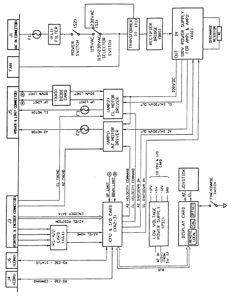
Figure B-5: BLOCK DIAGRAM - Dwg. No. 20-0094

RDACS User’s Guide August 2000
i

RDACS User’s Guide August 2000
ii
Table of Contents
1. Introduction………………………………………………………………………………..
1
2. RDACS Terminal Window……………………………………………………………….
2
3. RDACS Config……………………………………………………………………………. 3
3.1 File Pull-Down Menu…………………………………………………………………….. 3
3.2 Connect Commands…………………………………………………………………….. 4
3.3 A-Scope Commands…………………………………………………………………….. 5
3.4 Control Commands……………………………………………………………………… 8
3.5 Configuration Commands……………………………………………………………… 17
4. Configuration Commands……………………………………………………………….. 36
5. Installing RDACS………………………………………………………………………….. 39
6. The radacs.ini Configuration File………………………………………………………. 41
6.1 Start-Up Section…………………………………………………………………………. 45
6.2 Master Section…………………………………………………………………………… 50
6.3 Site Section……………………………………………………………………………….. 53
6.4 RadPgmN Section……………………………………………………………………….. 57
6.5 Antenna Sections………………………………………………………………………... 63
6.6 LevelN Section…………………………………………………………………………… 67
6.7 ModeN Section…………………………………………………………………………… 70
6.8 AntennaCmds Section………………………………………………………………….. 91

RDACS User’s Guide August 2000
iii
Preface
This manual describes the operating procedures for Baron Service’s RDACS software
program that is delivered with the Neighborhood Radars™
Document Organization
The information in this manual is organized as follows:
Section 1 describes the RDACS Terminal Window, which acts as the radar
system’s log and provides a few controls.
Section 2 describes the RDACS Config utility, which lets you perform a
limited number of system controls from the Radar Control dialog box.
Section 3 is a step-by-step procedure for accessing RDACS controls while
operating FasTrac.
Section 4 describes the installation instructions for RDACS.
Related Documentation
The following manual provides in-depth information about RVPtty:
RVP7™ Digital IF Receiver and Doppler Signal Processor User’s Manual.
Describes the operating and troubleshooting procedures for SIGMET, Inc’s. RVP7
Doppler Signal Processor.
Type Faces
Italic: Indicates a document title, the first occurrence of a new term, a directory or
file name, or a system response that explains what the system is doing. For
Example: The monitor displays current parameters.
RDACS User’s Guide August 2000
iv
Bold: Indicates an item in the graphical interface, such as the OK button or a
command button.
Courier: Indicates information you type. For example: Set the signal
processor parameters by typing: SOPRM
Symbols
The following document conventions are used throughout this manual:
Information that is not critical to system operation but describes useful
procedures or information that will optimize system operation.
Very important about a command or a procedure.
Critical instructions that must be followed to prevent injury or loss of
data.

RDACS User’s Guide August 2000
v
Keyboard Conventions
ALT
Alternate key. For example, ALT+x means hold down the Alternate key
and press x.
CTRL
Control key. For example. CTRL+c means hold down the Control key
and press c.
DEL
Delete key.
Enter
Return/enter key.
ESC
Escape key.
SHIFT
Shift key.
TAB
Tab key.

RDACS User’s Guide August 2000
vi
Terminology
Click
To position the pointer on the screen, and then to press and quickly
release the left mouse button.
Double Click
To quickly press and release a mouse button twice without moving
the mouse. This action is used as a shortcut for common actions,
such as activating an icon, opening a file, or selecting a word or a
graphic element.
Drag
To press and hold a mouse while moving the mouse. This action is
used to identify a range of objects, to move objects, or to resize
objects.
Enter
To input information by typing or by using the mouse.
Identify
To locate an element on the screen either by clicking it or by typing
the name.
Press and hold
To press and hold down a mouse button to perform an action, such
as resizing a window.
Scroll
To move through text or graphics
Select
To click a button, a text box, an item in a list, or some other item on a
dialog box, menu, or window.
Type
To key in data. To complete this action, you may also need to click
OK, press ENTER, or press TAB.
What to Expect from this Document
This document describes how to install, start, and run the RDACS program.
RDACS User’s Guide August 2000
1
1. Introduction
This manual describes the Radar Acquisition and Control System (RDACS), which gives
users remote control over many radar system operations. The remainder of this manual
is comprised of four main sections:
1. The RDACS terminal window, which is accessed by Start BSI RDACS.
2. The Radar Control dialog box, which is accessed by Start BSI Config
RDACS.
3. The RDACS window that is installed in FasTrac.
4. The RDACS installation instructions.
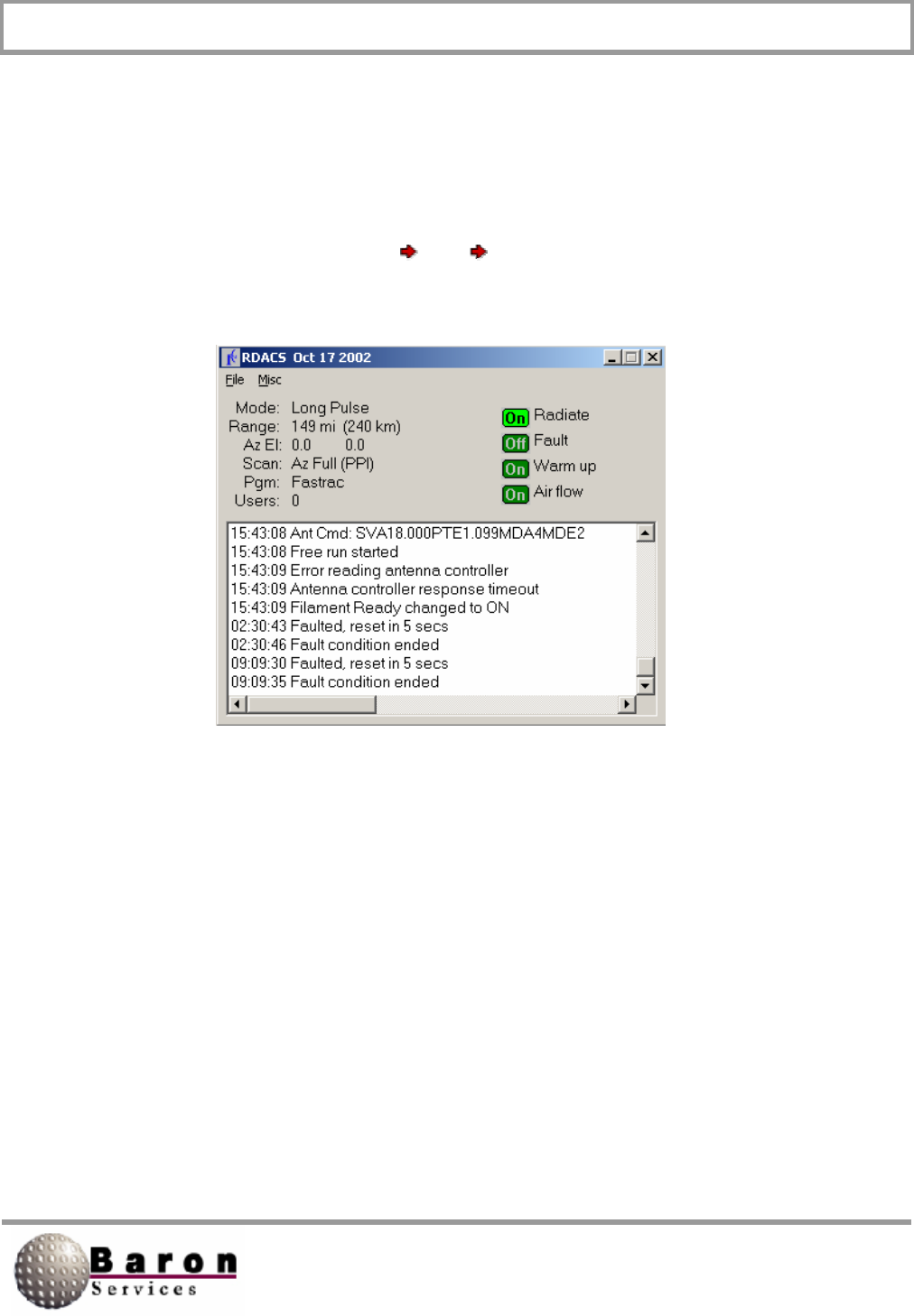
RDACS User’s Guide August 2000
2
2. RDACS Terminal Window
The RDACS terminal window acts as the radar system’s log and provides few controls.
The main display lists the time and type of radar system commands. The commands can
be issued from Config RDACS or from FasTrac real-time operations. The following
window displays when you select Start BSI RDACS. (Start is located next to the
taskbar on bottom of your terminal screen.)
The File menu has only one subcommand, Exit.
The Misc menu has three subcommands: Gparm, Log scans, and List users.
1. Gparm accesses the status information for the radar system.
2. Log scans displays information about a complete antenna scan similar to the
following: Scan complete: 39 seconds, 361 rays, 0 too big, small 1.0, large
1.0
3. List users displays the following information about users who are remotely
logged into your system’s RDACS: ID, State, User name, Address, Log-In
time, and Log-Out time.
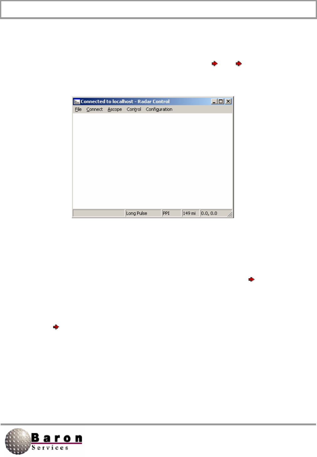
RDACS User’s Guide August 2000
3
3. RDACS Config
The RDACS Config utility lets you perform a limited number of system controls from the
Radar Control dialog box, which is accessed by selecting Start BSI Config
RDACS.
3.1 File Pull-Down Menu
The File pull-down menu has only two options: About and Exit. Select File About to
open a message box that indicates the name of the software package, the version
number, and the copyright date. Click OK to dismiss the message box.
Select File Exit to terminate the RDACS Config session.
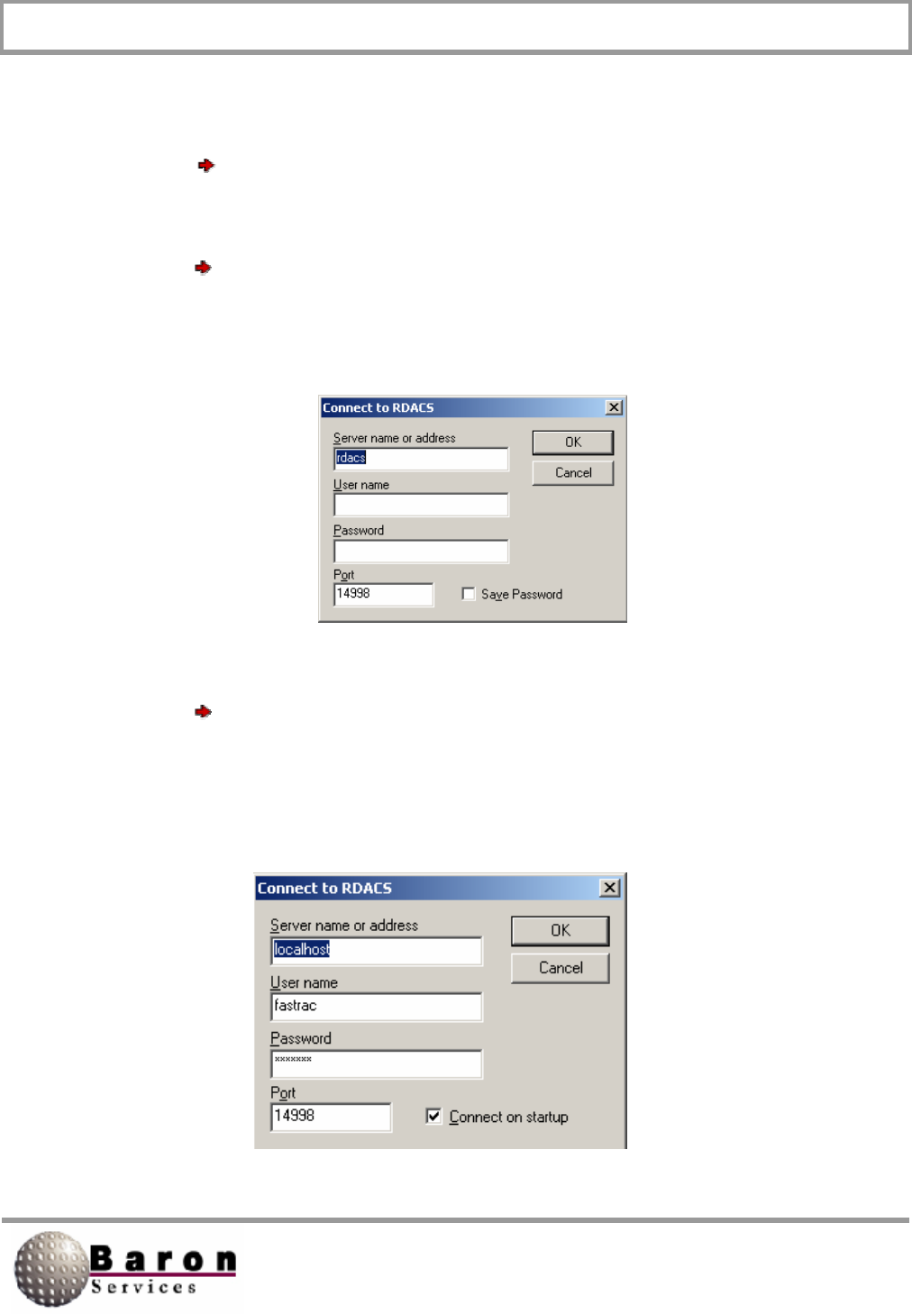
RDACS User’s Guide August 2000
4
3.2 Connect Commands
The Connect commands let you remotely view and control another site’s RDACS.
Select Connect Disconnect to end remote control mode.
A connect to RDACS dialog box, similar to the one shown below, displays when you
select Connect Connect. You must know the server name or address, your user
name, your password, and the port designator to connect remotely to RDACS. See your
System Administrator for the required inputs.
A Connect to RDACS dialog box, similar to the one shown below, displays when you
select Connect Auto connect. This dialog box lets you log onto the specified server
to remotely view and control RDACS. The controls on this dialog box are similar to the
Connect to RDACS dialog box, except you automatically are connected to the specified
server when you start up RDACS and you cannot save your password.
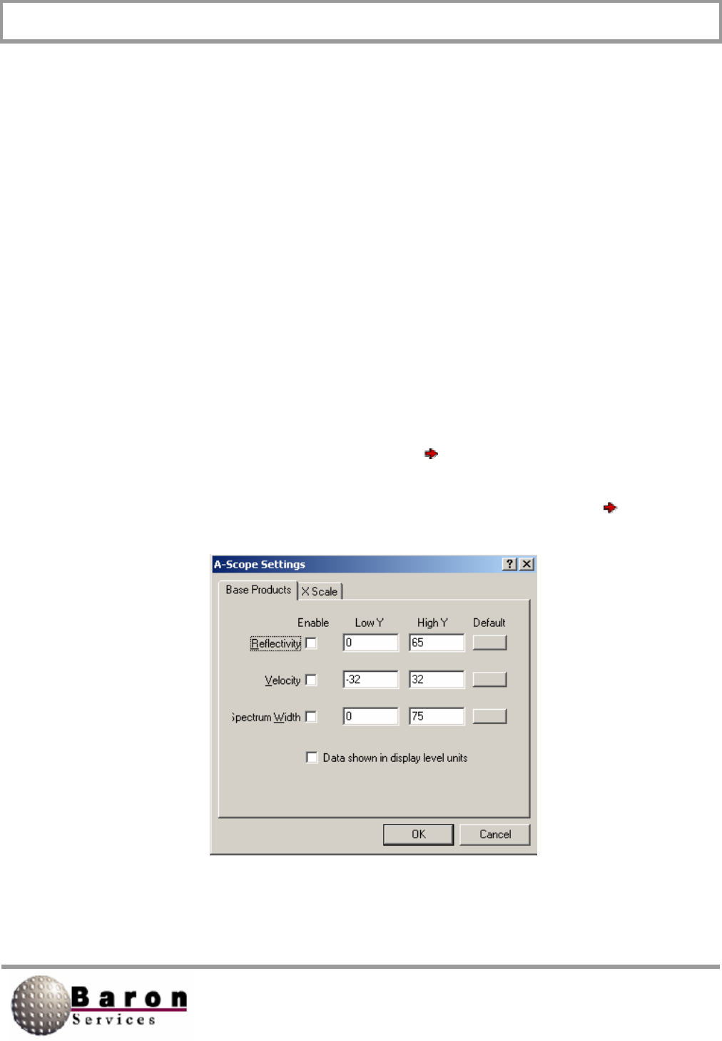
RDACS User’s Guide August 2000
5
3.3 A-Scope Commands
The A-Scope commands let you configure the A-Scope presentation of return data, in
signal strength and in either distance or in time. You can use the A-Scope commands to
display three types of radar data (reflectivity, velocity, and spectrum width) and to set the
display limits.
3.3.1 A-Scope Settings
The A-Scope displays the radar data, where the horizontal axis (X) displays time and the
vertical axis (Y) displays signal strength. The A-Scope Settings command lets you
configure the display shown when you select A-Scope Enable.
The following, double-tabbed dialog box displays when you select Oscilloscope
Settings:

RDACS User’s Guide August 2000
6
This Base Products section of this dialog box lets you select which radar products will
be shown on the A-Scope display. When you select a radar product, you must either
select the Data shown in display level units’ option to enable the default values or key
in the Low Y and High Y values.
Control Description
Reflectivity
Enables the computer algorithms that measure the linear
radar reflectivity factor (z) in m6/m3.
Velocity
Enables the computer algorithms that measure the winds in
the atmosphere.
Spectrum Width
Enables the computer algorithms that transform time-series
data into the frequency domain. In other words, it
determines the average frequency as well as the
distribution of frequencies, thus providing data about storm
turbulence.
Data shown in display
level units
You must select this option to enable Default option.
OK
Accepts your changes, and returns you to the main RDACS
dialog box.
Cancel
Ignores any changes, and returns you to the main RDACS
dialog box.
The X Scale portion of the dialog box controls the A-Scope’s horizontal display. You
must either select the Auto Scale option or specify the Low X and High X values.
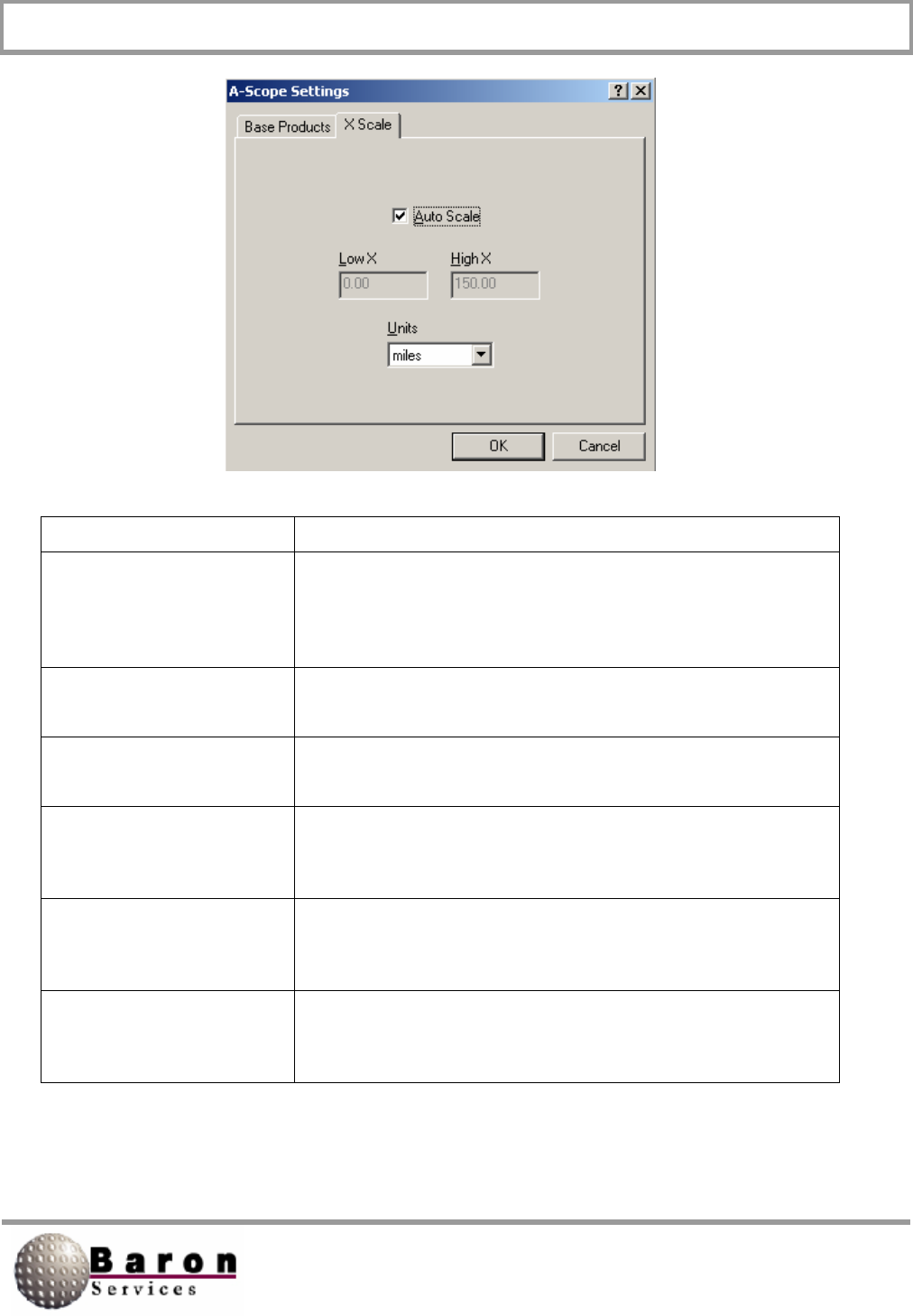
RDACS User’s Guide August 2000
7
Control Description
Auto Scale
Automatically controls the low and high range for the
horizontal axis. When selected, the Low X and High X
fields are disabled.
Low X
Specifies the lowest range for the horizontal axis.
High X
Specifies the highest range for the horizontal axis.
Units
Specifies the unit for the horizontal axis measurements:
miles, nautical miles, kilometers, or microseconds.
OK
Accepts your changes, and returns you to the main RDACS
dialog box.
Cancel
Ignores any changes, and returns you to the main RDACS
dialog box.
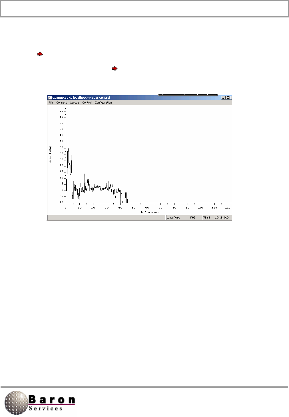
RDACS User’s Guide August 2000
8
3.3.2 A-Scope Display
An A-Scope Display, similar to the one pictured below, appears when you select A-
Scope Enable. It is a real-time display, reflecting the parameters you set under A-
Scope Settings. Select A-Scope Disable to remove the display and to return to the
main Radar Control dialog box.
3.4 Control Commands
The Control Commands let you set most of the radar’s controlling parameters, as
described in the following subsections. Remember, some of the controls can also be
changed by:
1. Editing the rdacs.ini file.
2. Performing real-time system manipulations in the FasTrac program.
In either case, the last issue change is the one under which the radar system operates.
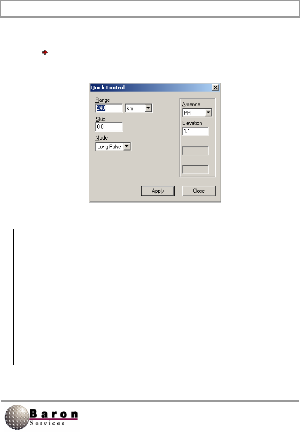
RDACS User’s Guide August 2000
9
3.4.1 Quick Control
A Quick Control dialog box, similar to the one shown below, displays when you select
Control Quick. Observe the RDACS display when you issue commands form this
dialog box, and verify that the system is operating as expected.
Control Description
Range
Defines the maximum distance from the radar antenna to
the target. You may specify the range measurement in
miles, kilometers, or nautical, miles. If you have a single or
double-pulse Doppler radar, range is usually 75 miles. If
your system is in Log mode, range is usually 300 miles.
Remember, the lower the range, the higher the resolution
for closer targets. If you set a range that is greater than the
maximum allowed for your radar type, RDACS uses the
maximum valid range and displays the correct value.

RDACS User’s Guide August 2000
10
Control Description
Skip
Sets the radar sampling skip distance in miles. For
example, a value of 2.5 means that data sampling begins
2.5 miles from the radar. Use this option to remove the
display of the strong signal that is received just after the
radar pulse is transmitted. A typical value for Skip lies
between 0.5 to 5.0 miles (the default value is 1.0).
Mode
Controls the system mode as selected from the pull-down
menu: Not all modes are available for all radars. Only the
available modes are displayed.
Power Down turns off the radar electronics. It may take
several minutes before the radar cools and the power is
removed.
Standby turns off the transmitter (it no longer radiates),
while the radar electronics remain on.
Log places the radar in long-pulse mode, which is up to
300 miles in range and provides no velocity product.
Log + Turb places the radar in log mode, and the system
displays turbulence from the receiver data.
Long Pulse places the radar in long pulse mode, which is
up to 300 miles in range.
Single PRF places the system in single-pulse Doppler
mode. Range is set to 75 miles and the pulse tolerance is
set to +/- 16 µs.
VHD places the system in Very High Definition (dual-pulse)
Doppler mode. Range is set to 49 miles, and pulse
tolerance is set to +/- 38 µs.
Dual PRF places the system in dual-pulse Doppler mode.
Range is set to 75 miles, and the pulse tolerance is set to
+/- 32 µs.
No Radiate turns off your radar system. It may take several
minutes before the transmitter cools and power is removed.

RDACS User’s Guide August 2000
11
Control Description
Antenna
Defines the antenna Scan mode: PPI, Stop, Sector, or
RHI. PPI (plan position indicator) mode displays a 360-
degree sweep in azimuth at the specified elevation angle.
(This is the normal operating modes)
Stop scans weather only within the specified azimuth and
elevation levels. This mode is useful for investigating a
particular storm cell.
RHI (range-height indicator) shows the distance from the
radar at the specified azimuth angle and displays the height
above the radar on the vertical axis, from El 1 to El 2. (Note
that RHI exaggerates the vertical size of an echo, giving a
distorted impression of the actual storm. The angular
resolution of the radar increases as the beamwidth
decreases, so the narrower the beam, the lesser the size of
the echo.)
Sector performs a pie-shaped track at the set azimuth,
within the specified span, at the set elevation level.
Apply
Puts the new specifications into operations, and returns you
to the main Radar Control window.
Close
Ignores any changes you have made, and returns you to
the Main Control window.
3.4.2 Extended Control
The Extended Control dialog box is similar to the Quick Control dialog box described in
Section 1.4.1 except you have two additional options: Preferred Product and Duration.

RDACS User’s Guide August 2000
12
Preferred Product lets you specify which algorithms the computer applies to the
decluttered, dealiased, and range-unfolded return data to produce the selected product.
You can select the following items from the pull-down menu: No preference, Log
intensity, Linear intensity, Velocity, or Turbulence.
1. No preference indicates that clean, quality-checked return data will be
displayed.
2. Log Intensity measures reflectivity in logarithmic values. Z is the logarithmic
reflectivity factor measured in units of dBZ (decibels relative to a reflectivity 1
mm6/m3 )
3. This is a convenient method for compressing reflectivity measurements to
numbers that are more convenient than the larger values of the
corresponding linear intensity measurements.
4. Linear intensity measures the linear radar reflectivity factor (z) in m6/m3.
5. Velocity measures the winds in the atmosphere.
6. Turbulence measures velocity variances that exceed set thresholds. The
higher the variance, the greater the turbulence.
7. Duration specifies the transmitter’s pulse duration measured in the specified
units: seconds or cycles.
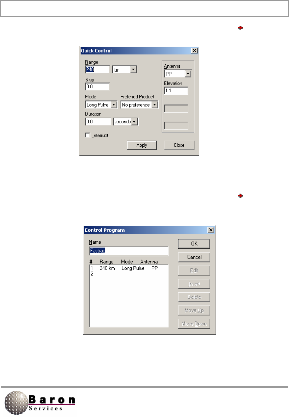
RDACS User’s Guide August 2000
13
A dialog box similar to the one shown below, displays when you select Control
Extended:
3.4.3 Program Control
A dialog box similar to the one shown below, displays when you select Control
Program:

RDACS User’s Guide August 2000
14
Control Description
Program List
Displays saved programs
OK
Accepts your changes, and returns you to the main RDACS
dialog box.
Cancel
Ignores any changes, and returns you to the main RDACS
dialog box.
Edit
Lets you modify program parameters.
Insert
Lets you introduce a new program.
Delete
Deletes the selected program.
Move Up
Moves you up through the program list.
Move Down
Moves you down through the program list.
3.4.4 Inputs and Outputs
The Input/Output control combines several functions:
1. The User Defined options let you test the Digital Signal Processor’s input
and output buses. If everything is working correctly, the Fault indicator will
remain unlit.
2. The Radiate command lets you turn on the transmitter.
3. The Fault, Filament ready, and Airflow Good indicators let you monitor
system status. These indicators do not change dynamically after you open
the Input/Output dialog box. You must press the Refresh Status button to
update the status indicators.
4. The Reset Modulator sends a reset pulse to the modulator circuitry. This
normally clears any system fault interlock logic. (If the fault condition persists,
the fault interlock logic may cause a new fault again.)
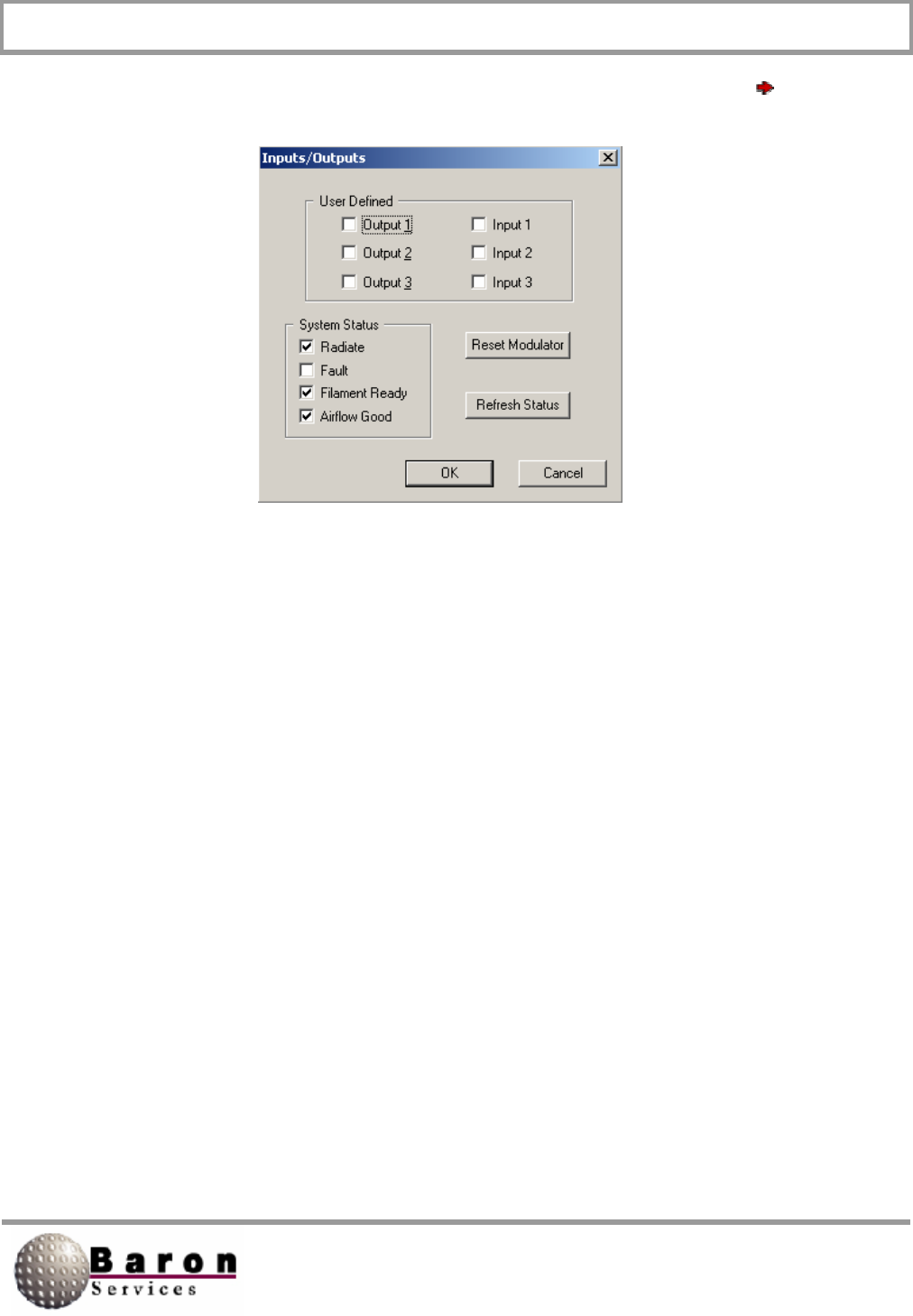
RDACS User’s Guide August 2000
15
A dialog box, similar to the one shown below, displays when you select Control
Input/Output:
3.4.5 Resample Noise
There are two types of input signals to the receiver: the signal from a particular target
and the signal generated by the radar system, which is referred to as noise. The
Resample Noise command measures the receiver noise so it can be subtracted from
subsequent measurements. During the resampling process, the internal trigger
generator is temporarily set to a special noise rate that is usually much lower than the
operating rate. You must verify that no returned power is present within the sampling
interval. You may have to raise the antenna during resampling to avoid thermal noise
from the ground or from weather targets.
After power-up, you should issue this command at least once before the system begins
to receive and process data. You should also occasionally issue the command to
compensate for drift, both in the radio frequency system and in the analog-to-digital
converter system. Finally, you must reissue the Resample Noise command when you
change the rate or range.

RDACS User’s Guide August 2000
16
When you issue the Resample Noise command, lines similar to the ones shown below
appear on the RDACS terminal display.
Free run stopped
SNOISE: Noise=1609 DiagA=0000 DaigB=0000 Imm1=42A0 Imm2=0301
Latch=0000
Free run started
The following list describes each word in the listing:
Parameter Description
Noise
Indicates the log of the measured noise level.
DiagA
Indicates the measured DC offset for the I channel.
DaigB
Indicates the measured DC offset for the Q channel.
Imm1
Imm2
Latch
Indicates if failures were detected during noise sampling.
Check command to verify that everything is working
correctly.
If failures are detected during the noise measurement, status bits will be set in the Latch
word.
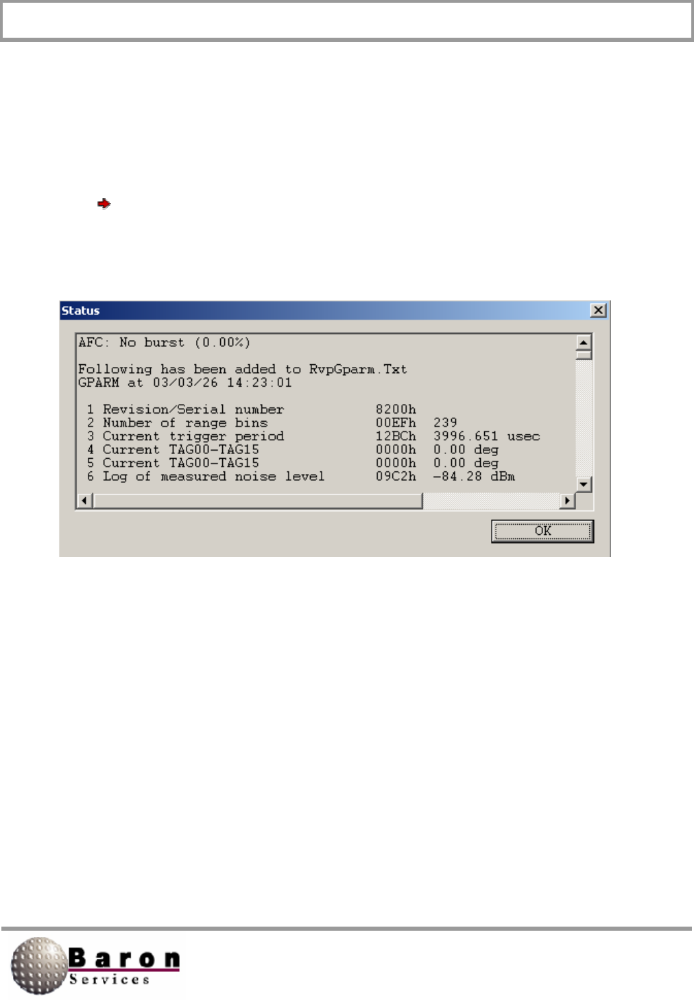
RDACS User’s Guide August 2000
17
3.4.6 Status
A current status listing, similar to the one shown below, displays when you select
Control Status. The displayed data are accessed from the Digital Signal Processor
(the RVP7) and are described in the “Get Processor Parameters” section in the RVP7
Digital IF Receiver User’s Manual.
3.5 Configuration Commands
The Configuration commands let you specify the site parameters, control the antenna,
and edit the RDACS.ini file.
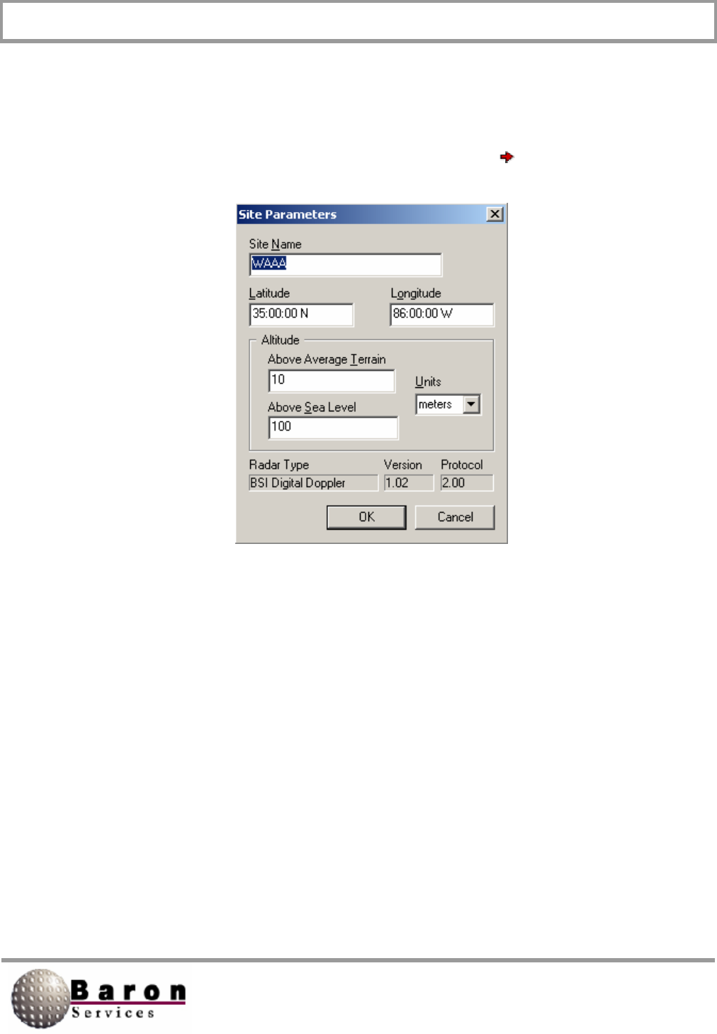
RDACS User’s Guide August 2000
18
3.5.1 Configuration Site Parameters
The following dialog box displays when you select Configuration Sites:
While most of the dialog box controls are user-definable, the fields are set during system
configuration and should not be changed. The parameters correspond to the Site section
of the radacs.ini file. The bottom three fields, Radar Type, Version, and Protocol, are
read-only parameters that are set by the software. Review the site parameters, and click
OK to dismiss the dialog box.
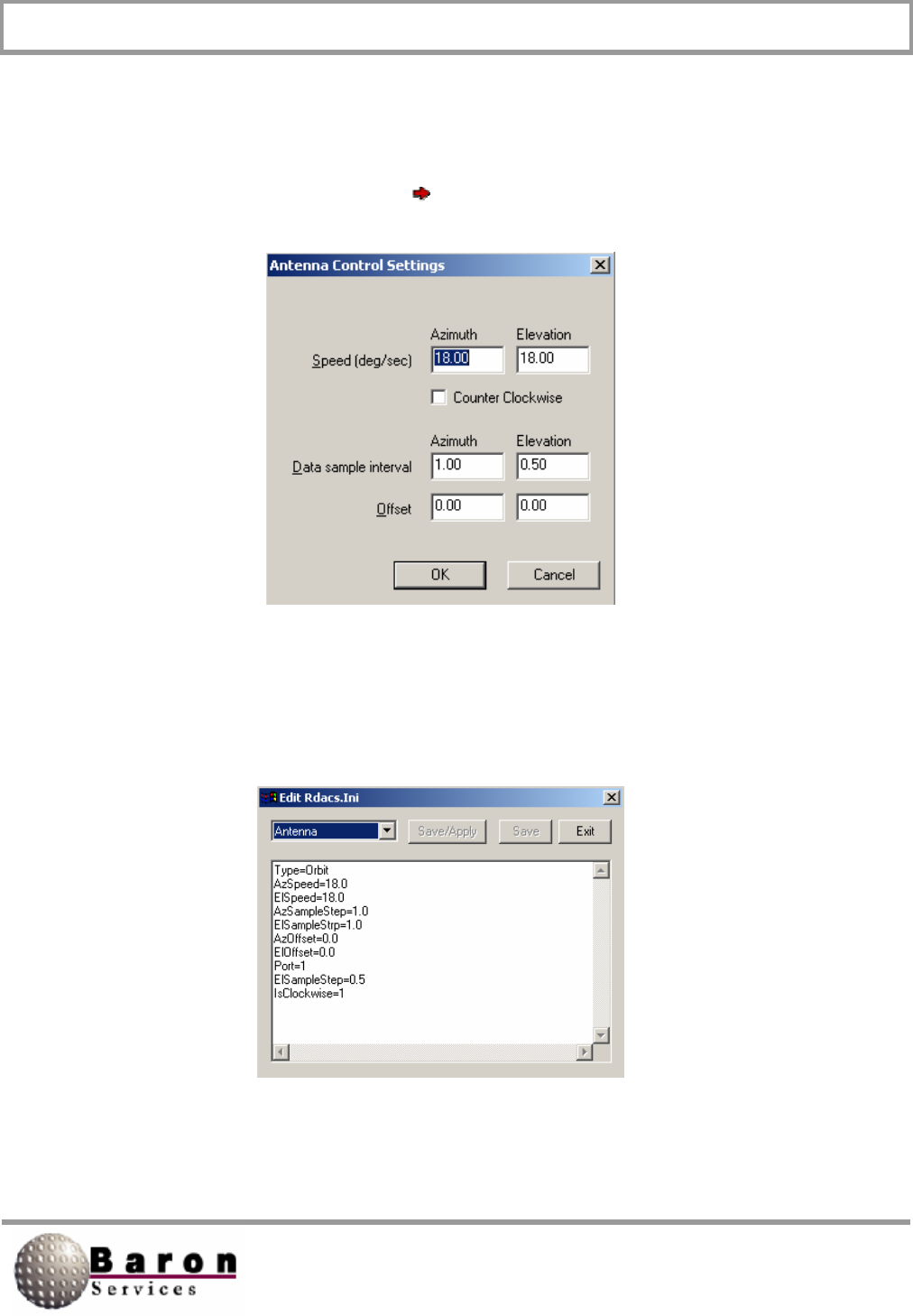
RDACS User’s Guide August 2000
19
3.5.2 Antenna Control Settings
The Antenna Control Settings dialog box controls the speed and direction of the radar
antenna, as well as the data sample interval and offset rates. The following dialog box
displays when you select Configuration Antenna:
The controls are self-explanatory. When you click OK to accept your changes, note that
an Antenna command is reflected in the RDACS display. The commands input from the
Antenna Control Settings dialog box correlate to the Antenna section in the rdacs.ini file,
as shown below.
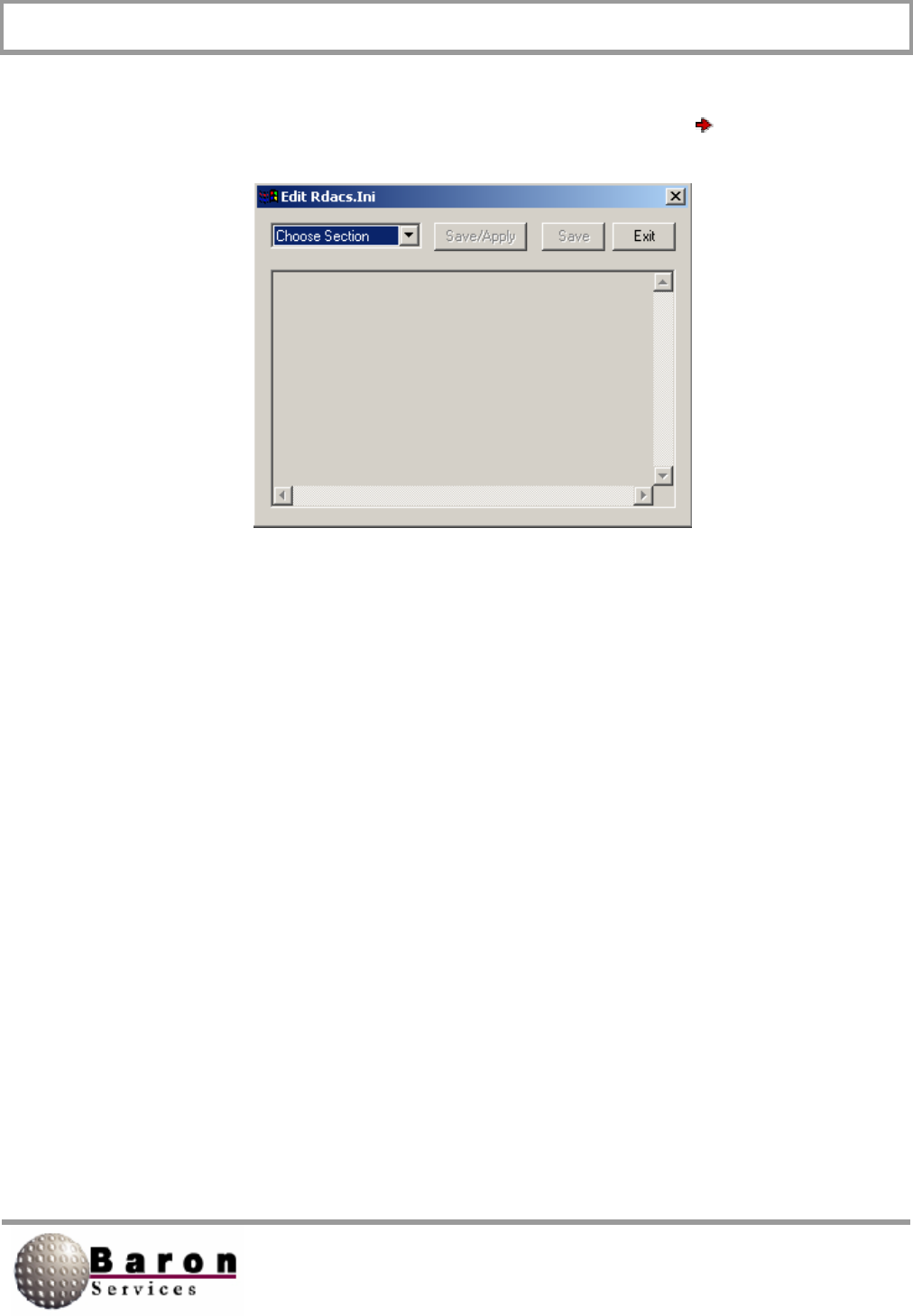
RDACS User’s Guide August 2000
20
3.5.3 Editing the rdacs.ini File
The Edit Rdacs.Ini dialog box displays when you select Configuration RDACS.Ini.
The top leftmost drop-down menu lets you select a section in the rdacs.ini file, which you
can then view and edit, as required. The rdacs.ini file has several sections: Startup,
Master, Site, RadPgm0, RadPgmAntennaStuck, CrossRefTables, six Mode tables,
ModeDefault, five Level tables, Antenna, and AntennaCmds. Regardless of which
section you choose to edit, there are three controls: Save/Apply, Save, and Exit.
Save/Apply saves your edits and puts them into operation immediately. Save saves
your edits, but they will not become effective until the next time you enter RDACS. Exit
ignores your edits, asks if you want to save your edits, terminates the editing session,
and returns you to the Radar Control dialog box.
Section lines beginning with the # character are notes that provide important information
about parts of the rdacs.ini file. The following paragraphs describe each section of the
radacs.ini file. While most parameter values are not specified, important values that
should be included in the rdacs.ini file are specified.

RDACS User’s Guide August 2000
21
Startup Section
NumUsers=
WatchDogType= Set to any value from 0 to 20 (0 disables
WatchDog). When Watchdog detects that the I/O interface between
the Digital IF Receiver and the RDACS computer is malfunctioning
for the specified time (in seconds), the system performs a
complete reset operation.
TcpNoDelayUsers=
AntennaMoveTimeout=
#DIOPort=O
#DIOPort=0x02a8
DIOPort=
Logscans=
AutoFaultResetDelay=
Master Section
CfgVersion=
# do not change the next three while rdacs runningNumModes
NumLevels=
NumRadPgmS
# do not change the next three while rdacs running
RangeResolution0=
RangeResolution1=
RangeResolution2=
RangeResolution3=
# always set to 1
SepNoiseLevels=l
# if 1, use defaults in rvp
NoNoiseCmds=
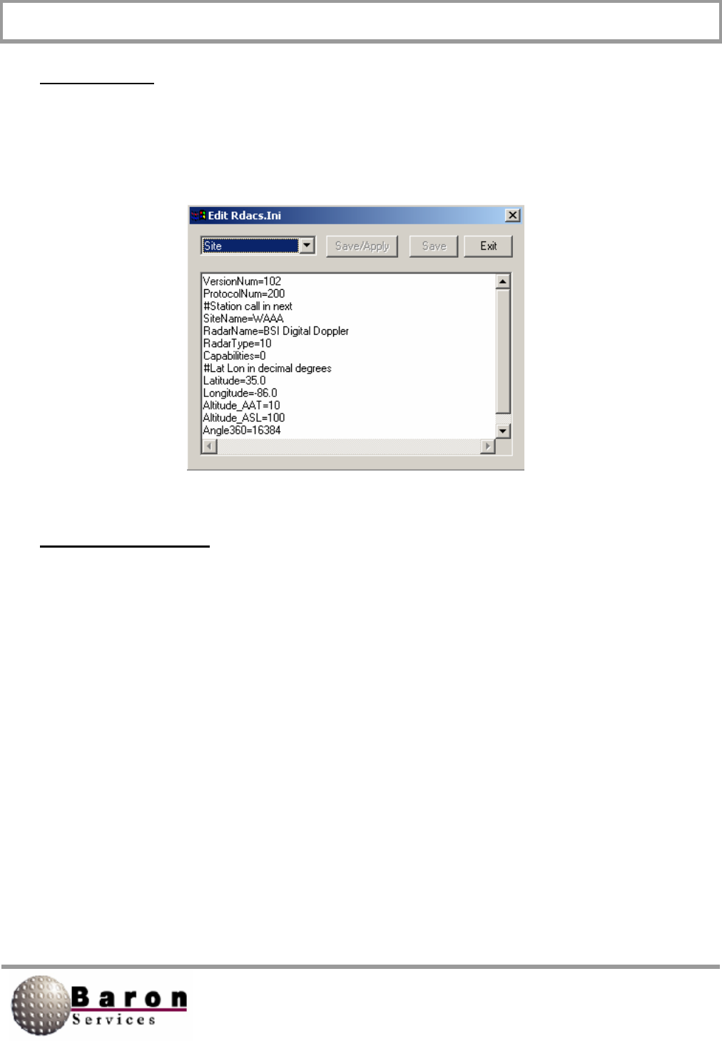
RDACS User’s Guide August 2000
22
Site Section
The Site section of the rdacs.ini file contains many of the parameters described in
Section 2.5.1, Configuring Site Parameters. These items, which are either set at system
installation or are set by the software, should not be changed.
RadPgm0 Section
# the mode on startup
Title=
NumSteps=
AntOp0=
# this is the RdpModeNum
Mode0=0xl
Range0=
Skip0=
Duration0=
Az0=
E10=
EndPt0=

RDACS User’s Guide August 2000
23
RadPgmAntennaStuck Section
Title=Antenna Stuck
NumSteps=
AntOp0=
# this is the RdpModeNum
Mode0=0xO
Range0=
Skip0=
Duration0=
Az0=
E1O=
EndPt0=
CrossRef Tables Section
# this section notes the mode to rdpmode xref
# it is not used by rdacs
mode0=rdpmode4 powerdown
mode1 =rdpmode0 standby
mode2=rdpmode1 long pulse
mode3=rdpmode2 single prf
mode4=rdpmode3 dual prf
mode5=rdpmode5 clear air
# level tables:
level0=reflectivity 5-75 dBZ
level1=speed for width,
level2=speed for single prf +/- 20 kts
level3=speed for dual prf +/- 99 kts
level4=reflectivity for clear air -28 to 28 dBZ

RDACS User’s Guide August 2000
24
Mode0 Section
RdpModeNum=4
Name =”PowerDown”
Radiate=
PowerUp=
Mode1 Section
RdpModeNum=0
Name=”Standby”
Radiate=0
#force reset forces a modulator reset when
# mode is entered
ForceReset=l

RDACS User’s Guide August 2000
25
Mode2 Section
LogThreshold=Sets the upper limit for reflectivity values.
Reflectivity values below this number may be discarded. This
value is always positive.
CalRef1=
RdpModenUM=1
Name=LongPulse
Radiate=
RAvail=
VAvail=
WAvail=
PRF=
Pulselndes=
Unfold=
# #
FilterRange0=
Filterlndex0=
FilterRange1=
FilterIndex1=
FilterRange2 =
Filterlndex2=
FilterRange3=
Filterlndex3=
SampleSize=Specify from 1 to 256 pulses.
CMS=usedefault
Lsr=usedefault
Dsr=usedefault
Ccorthreshold=usedefault
SqiThreshold=usedefault
SigThreshold=usedefault
ThCt1Uncorr=usedefault
ThCt1Corr=usedefault
ThCt1Vel=usedefault
ThCt1Width=usedefault

RDACS User’s Guide August 2000
26
Mode3 Section
RdpModeNum=2
Name=”Single PRF”
Radiate=
Vlevel=
RAvail=
VAvail=
WAvail=
PPF=
PulseIndex=
Unfold=
# #
FllterRange0=
Filterlndex0=
FilterRanqe1=
Filterlndex1=
FilterRange2=
Filterlndex2=
FilterRanqe3 =
Filterlndex3=
SampleSize=Specify 1 to 256 pulses.
CMS =
Lsr=
Dsr=
LogThreshold=
CcorThreshold=usedefault
SqiThreshold=usedefault
SigThreshold=usedefault
CalRef1=usedefault
ThCt1Uncorr=usedefault
ThCt1Corr=usedefault
ThCt1Vel=usedefault
ThCt1Width=usedefault

RDACS User’s Guide August 2000
27
Mode4 Section
RdpModeNum=3
Name=”Dual PRF”
Radiate
VLevel=
RAvai1=
VAvail=
WAvail=
PRF=
PulseIndex=
Unfold=
# #
FilterRange0=usedefault
Filterlndex0=usedefault
FilterRange1=usedefault
FilterIndex1=usedefault
FilterRange2=usedefault
Filterlndex2=usedefault
FilterRanqe3=usedefault
Filterlndex3=usedefault
SampleSize=usedefault
CMS=usedefault
Lsr=usedefault
Dsr=usedefault
LogThreshold=
CcorThreshold=usedefault
SqiThreshold=usedefault
SigThreshold=usedefault
CalRef1=
ThCt1Uncorr=usedefault
ThCt1Corr=usedefault
ThCt1Vel=usedefault
ThCt1Width=usedefault

RDACS User’s Guide August 2000
28
Mode5 Section
LogThreshold=
CalRef1=
RdpModeNum=5
Name=”NoRadiate”
Radiate=
RAvail =
VAvail =
WAvail=
PRF=
PulseIndex=
Unfold=
# #
FilterRange0=
Filterlndex0=
FilterRange1=
Filterlndex1=
FilterRange2=
Filterlndex2=
FilterRange3=
Filterlndex3=
SampleSize= Specify 1 to 256 pulses.
CMS=usedefault
Lsr=usedefault
Dsr=usedefault
CcorThreshold=usedefault
SqiThreshold=usedefault
SigThreshold=usedefault
ThCt1Uncorr=usedefault
ThCt1Corr=usedefault
ThCt1Vel=usedefault
ThCt1Width=usedefault

RDACS User’s Guide August 2000
29
ModeDefault Section
# O=standby l=log 2=singleprf 3=dual 4=powerdown 5=user...
RdpModeNum=
# mode name in fastrac and config menus
Name=”Default”
# set if mode should radiate
Radiate=
PowerUp=
# leveln table to use for color levels
# R, V, W=reflectivity, velocity, and width
RLevel=
VLevel=
WLevel=
# what products are available
RAvail=
VAvail=
WAvail=
# pulse width code, typ: O=2µs l=.8µs 2=user 3=user
PulseIndex=
# trigger frequency
PRF=
# maximum number of range bins
ReqNumBins=
# number of bins to average to product final bin
SamplesPerBin=
# up to 4 filters, range is in km. Index is 0 for # off, or 1 to
7 for increasing filtering. Lower # numbered filters should have
lower ranges
FilterRange0=
IndexRange0=
FilterRange1=
IndexRange1=
FilterRange2=
IndexRange2=
FilterRange3=
IndexRange3=
# procmode=1 sync command mode, =2 dynamic angle sync
# normally set to 2
ProcMode =
# unfold 0=none, 1=2:3, 2=3:4, and 3=4:5
Unfold=

RDACS User’s Guide August 2000
30
ModeDefault Section
# number of pulses to average
SampleSize= Specify 1 to 256 pulses.
# 0=horiz, 1=vert, 2=alternate
Polar=
# clutter microsupprresion
CMS=
# use three lag algorithms for width, signal power, and clutter
correction
R2=
# pulse end ray
End=
# reflectivity speckle removal
Lsr=
# doppler speckle removal
Dsr=
# rangle normalization and enables gas attenuation correction
Rnv=
# logslope typ=0.03
LogSlope=003
# logthreshold (must be >=0)
LogThreshold=
# clutter correction threshold
CcorThreshold=
# signal quality index threshold
SqiThreshold=
# signal power threshold
SigThreshold=
# calibration reflectivity
CalRef1=
# see SOPRM input 10 doc

RDACS User’s Guide August 2000
31
ModeDefault Section
TopMode=Specifies the processing mode, where 0000 Pulse Pair
Processing; 0001 = FFT Processing; and 0010 Random Phase
Processing.
AGCNumPulses=Specifies the number of pulses during one AGC
integration period.
Window=Specifies the type of window that is applied to time
series data where 0 Rectangle; 1=Hamming; and 2=Blackman.
ZER=Set to 1 to zero the clutter filter‘s internal state
variables before the delay time has elapsed.
FilterStabDly=Specifies time delay before processing the next
data ray. Used when dual-PRF velocity is enabled or when RVP7 has
been reconfigured by user commands.
# typ thctl vals: ffff = all pass, 0000 = all fail
# AAAA=log 8888=log & ccor AOAO=log & sqi
# weights sig: 8 sqi: 4 ccor: 2 log: 1
ThCt1Uncorr=
ThCt1Corr=
ThCt1Vel=
ThCt1Width=
ThCt1ZdrRefl=
# normally leave tag inverts 0
InvTagLow= 0
InvTagHigh= 0
# gas atten
GasAtten=Specifies the value for atmospheric attenuation,
measured in dB/kin. When the water vapor is higher than this
value, attenuation will be higher.
# zdr cal
ZdrCal0ff set = Specifies reflectivity depolarization ratio.
# radar wavelength
Wave length=Specifies the distance that the radar wave within one
cycle.
# use uncorrected (no range correction) ref1
productRUseUncorr=

RDACS User’s Guide August 2000
32
Level0 Section
# types 0=refl 1=speed
Type = 0
Name=Log
Units = dBZ
1=5
2=10
3=15
4=20
5=25
6=30
7=35
8=40
9=45
10=50
11=55
12=60
13=65
14=70
15=75
LeveI1 Section
Type = 1
Name=Width
Units=knots
1=2
2=4
3=6
4=8
5=10
6=12
7=14
8=16
9=18
10=20
11=24
12=26
13=28
14=30
15=32

RDACS User’s Guide August 2000
33
Level 2 Section
Type = 1
Name=Single PRF Vel
Units=knots
1=-20
2=-17
3=-14
4=-11
5=-8
6=-5
7=-2
8=0
9=2
10=5
11=8
12=11
13=14
14 =17
15=20
Level3 Section
Type=1
Name=Dual PRF Vel
Units=knots
1=-99
2=-64
3=-5O
4=-36
5=-26
6=-20
7=-1O
8=0
9=10
10=20
11=26
12=36
13=50
14=64
15=99

RDACS User’s Guide August 2000
34
LeveI4 Section
Type= 0
Name=Clear Air
Units =dBZ
1=-28
2=-24
3=-20
4=-16
5=-12
6=-8
7=-4
8=0
9=4
10=8
11=12
12=16
13=20
14=24
15=28

RDACS User’s Guide August 2000
35
Antenna Section
Type=Orbit
AzSpeed=45.0
ElSpeed=6.0
AzSampleStep=1.0
AzOffset=90.0
ElOffset=0.0
Port=1
ElSampleStep=0.5
IsClockwise=1
AntennaCmds Section
InitCmd1=C [500d]
#xCP vel4 acc3 boost2 prop3 inte3 diff3 zero1
#InitCmd2=ACPOO4O/200/05/006/000/350/0[r] [500d]
#InitCmd3=ECPOO4O/200/05/030/005/350/0[r] [500d]
InitCmd2=ACPOO4O/100/05/030/040/350/0[r] [500d]
InitCmd3=ECPOO2O/100/05/055/125/350/0 [r] [5OOd]
#xCL offlset5 dowrn-ccw5 up-cw5 zero1
InitCmd4=ACL [azoff] /00000/00000/000[r] [500d]
InitCmd5=ECL [eloff] /35800/09500/000[r] [500d]
AzFullCmd=G1V00000 [el] [cw] [azvel] 00000000000 [r]
StopCmd=GOV[r] [1500d] DDD [az] [el] [r]
#StopCmd=DDDO900001000 [r]
#AzSectorCmd=GCE [el] 00000 [cw] [elvel] 00000000000 [r] [1500d]
G1A [azcen] [azspn] [cw] [azvel] 00000000000 [r]
#ElSectorCmd=GCA [az] 00000 [cw] [azvel] 00000000000 [r] [1500d]
G1E [elcen] [elspn] [cw] [elvel] 00000000000 [r]
AzSectorCmd=G0 [r] [l000d] G1A [azcen] [azspn] [cw] [azvel] [el]
000000 [r]
ElSectorCmd=G0[r] [l000d] G1E [elcen] [elspn] [cw] [elvel] [az]
000000 [r]
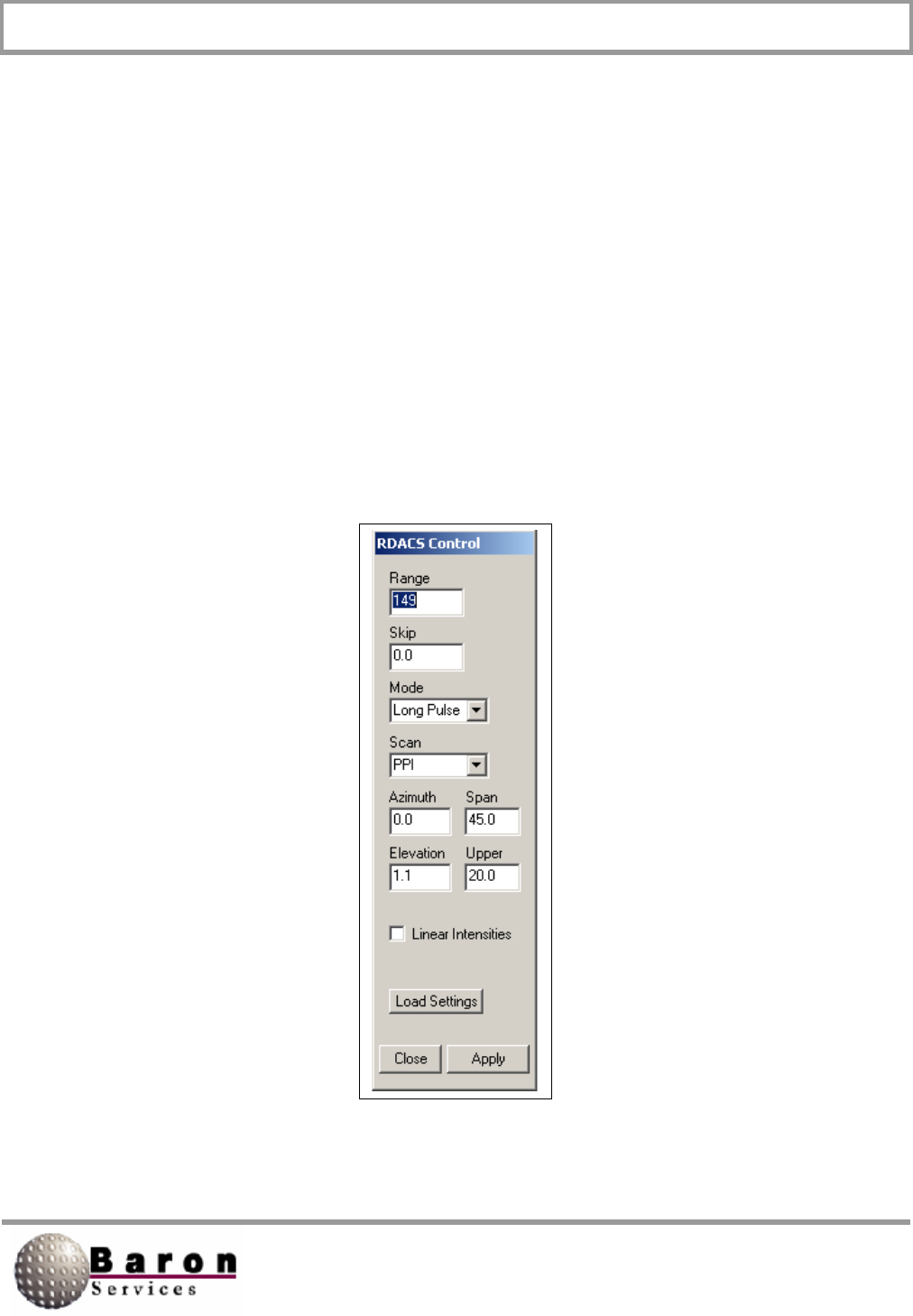
RDACS User’s Guide August 2000
36
4. RDACS Control from FasTrac
This section provides a step-by-step procedure for accessing RDACS control while
operating FasTrac.
1. Start the FasTrac program.
2. From the leftmost Select Panel area, select Views to open the View Main
panel.
3. Under the More Settings area on the bottom of the View Main panel, select
Data to open the View Data panel.
Under the More Radar Settings area in the middle of the View Data panel, select
Radar Control to open the RDACS Control panel.

RDACS User’s Guide August 2000
37
This menu is similar to that explained in the previous sections except you have two
additional options-Linear Intensities and Load Settings.
1. Linear Intensities determines which format of reflectivity data the radar uses
when it is one of the Doppler modes. If you do not select this option, the
radar uses Log reflectivity data.
a. The use of the Linear Intensities option depends on which version of the
RDACS controller executable is installed. If you have the early file,
HDDE.EXE, both linear reflectivity and log reflectivity are available. Since
log reflectivity data usually provides higher quality data, do not select this
option. If you have a later version of the RDACS controller executable,
H250S.EXE, you have access only to linear data and you must select this
option.
2. Load Settings accesses a saved RDACS configuration. You can use the
RDACS control program to create and save up to 10 configurations (numbers
0 through 9). Configuration 0 is loaded when you restart RDACS. You can
set other configurations to your personal preferences and needs. For
example, you can use a different color table to implement a clear-air mode in
Configuration 1. Configurations 8 and 9 are temporary saves of the test
configuration.
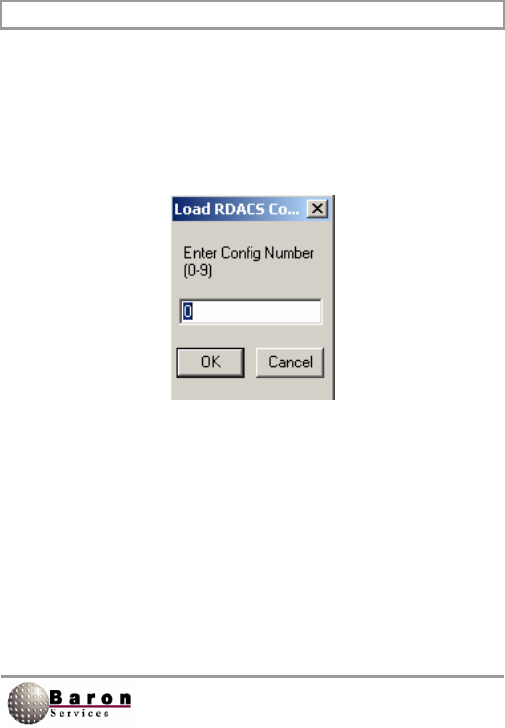
RDACS User’s Guide August 2000
38
After configuring the RDACS, select Load Settings to open the Load RDACS dialog
box.
Specify the configuration number, and click OK to return to the View Data panel.
OR
Click Cancel to dismiss the dialog box and to return to the RDACS Control panel.
RDACS User’s Guide August 2000
39
5. Installing RDACS
RDACS is normally set up when your system is delivered. The following
instructions are provided in case your system crashes, a new version is delivered,
or some other unusual circumstance occurs.
There is no separate installation program. Copying the executable file to its
destination and setting up shortcuts are manual operations.
The rdacs directory or folder must be created before you install RvpTty. The
steps below outline one possible way to set up the shortcuts to the program.
Those familiar with Microsoft Windows can use their preferred technique.
1. Copy the rdacs.exe file to your \rdacs directory.
2. RDACS will create the rdacs.ini file when it is needed.
3. Run Windows Explorer, navigate to the C. \ Windows\Start Menu\BSI folder,
and select File New Shortcut to open the Create Shortcut dialog box.
Note you may have to create the BSI folder.
4. Use the Browse function or key in the complete pathname for the
\rdacs\rdacs.exe file in the Command Line text box.

RDACS User’s Guide August 2000
40
5. Click Next, name the shortcut, and click Finish.
6. Select Start BSI, and verify that the new shortcut is displayed.
7. Right click on the desktop; then select New Shortcut from the popup
menu.
8. Use the Browse function or key in the complete pathname for the
\rdacs\rdacs.exe file in the Command Line text box.
9. Click Next, name the shortcut, and click Finish. A shortcut to RDACS will
appear on the desktop.

RDACS User’s Guide August 2000
41
6. The radacs.ini Configuration File
The rdacs.ini configuration file contains configuration parameters for RDACS. It is in text
format; therefore, you can use Notepad or any equivalent text editor to view and edit the
file contents.
The file is organized into sections. Section headings are on a line by themselves and
appear as a bracketed keyword, as shown in the following example:
[Startup]
NumUsers=10
WatchDogType=0
TcpNoDelayUsers=ndfastrac ndlocal wbay
AntennaMoveTimeout=0
#DIOPort=0
#DIOPort=0x02a8
DIOPort=PC17250
LogScans=0
AutoFaultResetDelaly=60
[Master]
CfgVersion=100
#Do not change the next three while RDACS is running
NumModes=60
NumLevels=5
NumRadPgms=1
# If next are changed, RVP7 must be configured
RangeResolution0=125.0
RangeResolution1=125.0
RangeResolution2+125.0

RDACS User’s Guide August 2000
42
For example, in our example file, [Startup] is the first section and [Master] is the second
section. Each section lists its associated variables and the current variable values
separated by equal (j signs. (For example, WatchDogType=1 enables the WatchDog
timer feature). Depending on the context, the value may be a real number, an integer, a
hexadecimal integer, a Boolean expression, or an alphanumeric string.
Note that variable names may or may not be case sensitive, depending on the context.
To ensure correct interpretation, use the variable names are they are specified in this
document.
There are three ways to change the configuration file, listed in order of preference:
By menu commands and dialog boxes in the RDACS Config program;
By using the Configuration Edit RDACS.ini menu command in the
RDACS Config program; and
By editing rdacs.ini with Notepad or an equivalent text editor.
For example, most of the variables in the Antenna section can be edited indirectly via
the Configuration Antenna command in RDACS Config. However, the Port variable
in that section must be edited through Notepad. In the ensuing descriptions, each
variable may include information on the best way to change it. If none is specified, open
RDACS Config and use the Configuration Edit RDACS.ini command to edit the file.
If this document discusses a variable that is not listed in your radacs.ini file, it will have
the default value.
The order of section variables discussed in this document is not important. In general,
variables are discussed in the order in which they are processed; sometimes, variable
descriptions are logically grouped.

RDACS User’s Guide August 2000
43
The following table lists the major configuration sections:
Section Title Description
Startup System startup information
Master Global configuration variables
Site Site-specific configuration
RadPgmN Saved scan programs
RadPgmAntennaStuck Scan program used if antenna fails to
rotate
Antenna Antenna configuration
LevelN Color/display level translate tables
ModeN Radar operational modes
ModeDefault Default settings for radar operational
modes
AntennaCmds Optional section when a TSA antenna
system is used
Other sections may also appear. For example, the system may make a section called
RebootRadPgm. The section and variable names are not case-sensitive; the order in
which sections and variables appear is also not important.
Note that sections ending in N indicate multiple sections ending in a number. In most
cases, the first number used is 0. For example, radacs.ini includes the Mode0 and
Mode1 sections. M and X are also be used to reference numbered sections and
variables.

RDACS User’s Guide August 2000
44
The subparagraphs describing each variable list the following items for each variable.
Item Description
Value Type Real, Integer, Hexadecimal Integer, Boolean, and/or String.
Range/Units Valid ranges of values/units of values, where applicable.
Default Value Value used if the variable is missing from rdacs.ini
Change Dynamically Specifies where there are any restrictions on changing the
variable value while RDACS is running
RVP7User’sGuide
Reference
Optional reference to RVP7 program commands (typically
this is only in the ModeN section).
The following are the various Value Types:
Real-Specifies a real number, optionally with a decimal point. The number
may be signed, depending on context. Any reasonable number of digits after
the decimal point is allowed; however, the value may be rounded to a fixed
number of significant digits.
Integer- Specifies a whole number; no decimal point is allowed. The number
may be signed, depending on context.
Hexadecimal Integer- Specifies a whole number in Base 16, with a Ox prefix.
Boolean-Specifies a numeric 1 or 0 representing true or false, respectively.
String-Specifies a sequence of printable characters. Spaces may be allowed,
depending on context.
In some cases, more than one value type is accepted. For example, a particular
configuration item may allow either an integer or the “none” string.
The remainder of this document describes each section and each variable within that
section.

RDACS User’s Guide August 2000
45
6.1 Startup Section
This section contains configuration variables that are related to system startup and user
options.
TcpNoDelayUsers [Startup]
Value Type: One or more user name strings, separated by spaces.
Range/Units: User names that are listed in the users.txt file.
Default Value: Empty.
Change Dynamically? Yes.
RDACS communicates with its users via TCP/IP, a networking protocol. When RDACS
turns the radar data into packets of data to send to the users, TCP/IP may bundle
several small packets of data into one larger packet. This packetizing process can
increase networking efficiency but it can cause the data to lose its real-time look,
especially in the case where the data is visualized as a real-time sweep, as in FasTrac.
However, TCP/IP has an option to turn this bundling off on a connection-by-connection
basis. When a user logs on with a name contained in the TcpNoDelayUsers list, RDACS
instructs TCP/IP not to bundle packets for that user. The tradeoff is that more bandwidth
is consumed on the network, so this should only be used as needed. User login names
for applications that do not display real-time data, such as RdacCap, should not appear
in the list.
Changes to this variable while RDACS is running only affect new connections.
RebootOnScsiError [Startup]
Value Type: Boolean.
Range/Units: 0 (disabled) or 1 (enabled).
Default Value: 1.
Change Dynamically? Yes.

RDACS User’s Guide August 2000
46
If the RebootOnScsiError variable is enabled (set to 1) and if (a) a fatal error occurs on
the SCSI to the RVP7 or if (b) the RVP7 does not seem to be responding, the RDACS
computer restarts. This allows the system to reset the SCSI hardware, and the RVP7 will
issue an internal reset when it detects that the SCSI interface is being initialized.
This option can be considered a watchdog on the RDACS/RVP7 interface, and it
normally should be enabled. If one of the described errors occurs, an entity is made in
the RDACSLog.txt file.
For this to be used in an unattended environment, the RDACS computer must be
configured to start RDACS (and any other desired applications) upon system boot. Also,
the RVP7 configuration item Respond to SCSI Reset (the RVPtty Mc command) should
be set to YES.
Before initiating reboot, RDACS creates the RebootRadPgm section in the rdacs.ini file.
This section contains the currently running scan program. It also contains the Active=1
variable, which lets RDACS know that it should run the scan program in the
RebootRadPgm section rather than the scan program in the RadPgm0 section.
DIOPort [Startup]
Value Type: Integer, hexadecimal integer, or string.
Range/Units: 0, 1, 2, 3, 4, I/O port address, or the string “PC17250’.
Default Value: Empty.
Change Dynamically? No, RDACS must be stopped.

RDACS User’s Guide August 2000
47
This variable defines the type of interface to the radar transmitter and status. There are
three types of interfaces: (1) an ISA bus I/O card, (2) a PCI bus I/O card model PCI-
7250, or (3) the RRC1 interface board integrated in the transmitter (serial interface).
To select (1), the ISA bus I/O card, enter the port address. For example,
enter DIOPort=0x260.
To select (2), the PCI bus I/O card, use DIOPort=PCI7250.
To select (3), the RRC1 interface, use 1, 2, 3, or 4 to select the COM1,
COM2, COM3, or COM4 serial port interface.
A value of 0 can also be used. In this case, there will be no transmitter control (the
transmitter can be operated in local mode and the status will be ignored).
AntennaMoveTimeout [Startup]
Value Type: Integer.
Range/Units: Timeout; enter 0 to disable or enter number of seconds.
Default Value: 300.
Change Dynamically? No, RDACS must be stopped.
If this variable is not 0, this variable specifies the timeout for taking action if antenna
motion is not detected. Typically, the action is to stop radiating. The actual scan program
that executes when the timeout occurs is specified in the RadPgmAntennaStuck
section.

RDACS User’s Guide August 2000
48
AutoFaultResetDelay [Startup]
Value Type: Integer.
Range/Units: Time between consecutive faults; enter 0 to disable or enter the
number of seconds.
Default Value: 0.
Change Dynamically? No, RDACS must be stopped.
This variable is used to configure automatic attempts to radiate if the radiate operation is
shut down due to a fault. When a fault is first detected, a transmitter reset is attempted in
five seconds. If another fault is detected, the number of seconds specified in the
AutoFaultResetDelay variable must elapse before RDACS resends the Reset signal.
LogScans [Startup]
Value Type: Boolean.
Range/Units: 0 (disabled) or 1 (enabled).
Default Value: 0.
Change Dynamically? Yes (use the RADACS Terminal window’s Misc Log
scans command).
When this variable is set, a message displays in the log window every time the antenna
passes through 0 degrees. The number of samples and the largest and smallest angles
sampled are displayed.
This can be useful to confirm correct antenna operation. Most of the time, it should be
disabled because it quickly fills up the log file (the log file is self-maintaining but other
useful information scrolls away faster).

RDACS User’s Guide August 2000
49
NumUsers [Startup]
Value Type: Integer.
Range/Units: 1 to 10 users.
Default Value: 5.
Change Dynamically? No, RDACS must be stopped.
Set the number of concurrent users supported by RDACS. A typical installation could
have the FasTrac, RadarNet Server, RdacCap, IRIS, and RDACS Config applications.
There is no harm in just setting the maximum, 10.
Consult Baron Services if more concurrent users are required.
WatchDogType [Startup]
Value Type: Integer.
Range/Units: 0 (disabled), 1, or 2.
Default Value: 0.
Change Dynamically? No, RDACS must be stopped.
This setting enables using the Watchdog timer feature available on some motherboards.
If the variable is set to 1, the system periodically inputs a byte on port 0x443 to enable
the Watchdog timer. It is disabled by inputting a byte on port 0x43.
If the variable is set to 2, the Watchdog timer is periodically enabled by outputting a
(byte) 5 on port 0x443. It is disabled by outputting a (byte) 5 on port 0x441.
If Watchdog is enabled and RDACS hangs for some reason, the computer will be reset
by the Watchdog hardware logic.

RDACS User’s Guide August 2000
50
6.2 Master Section
This section contains several global configuration variables. Two important variables are
NumModes and NumLevels. These must match the number of ModeN and LevelN
sections, respectively. In general, variables in this section should not be changed while
RDACS is running.
CfgVersion [Master]
Value Type: Integer.
Range/Units: 100.
Default Value: 100.
Change Dynamically? No, RDACS must be stopped.
Cfg Version specifies a software version tracking number that should not be changed.
NumModes [Master]
Value Type: Integer.
Range/Units: The number of mode sections defined.
Default Value: Empty.
Change Dynamically? No, RDACS must be stopped.
NumModes specifies the number of mode (ModeN) sections defined in the rdacs.ini file.
Each mode section specifies a particular operational configuration. By convention, the
first five mode sections are Powerdown, Standby, Long Pulse, Single PRF Doppler, and
Dual PRF Doppler.

RDACS User’s Guide August 2000
51
NumLevels [Master]
Value Type: Integer.
Range/Units: The number of level tables defined.
Default Value: Empty.
Change Dynamically? No, RDACS must be stopped.
NumLevels specifies the number of level conversion tables (the LeveIN sections) in the
rdacs.ini file. These tables are used to convert engineering units (e.g., dBZ or m/s) to
color levels. By convention, four tables are defined: Level0 through Level3. Normally,
Level0 is for reflectivity, Level1 is for spectrum width, LeveI2 is for single PRF
velocities, and Level3 is for dual PRF velocities.
RangeResolutionN (N = 0, 1, 2, or 3) [Master]
Value Type: Real.
Range/Un its: Selected values from 50.0 to 133.3/meters.
Default Value: 125.0.
Change Dynamically? No, RDACS must be stopped.
This variable specifies the range resolution for the four pulse-width configurations
supported by RVP7. The specified value must agree with that configured by the Range
Resolution option of the Mt<n> command of the RVP7. Valid values are 50.0, 58.3, 66.7,
75.0, 83.3 91.7, 100.0, 108.3, 116.7, 125.0, and 133.3.

RDACS User’s Guide August 2000
52
SepNoiseLevels [Master]
Value Type: Boolean.
Range/Units: 0 or 1.
Default Value: 1.
Change Dynamically? No, RDACS must be stopped.
SepNoiseLevels determines if separate noise commands should be issued for each of
the four possible pulse-width configurations. Normally, this should agree with the
Maintain separate noise levels for each PW item of the Mp command of the RVP7. The
recommended setting is 1.
NoNoiseCmds [Master]
Value Type: Boolean.
Range/Units: 0 or 1.
Default Value: 0.
Change Dynamically? No, RDACS must be stopped.
Setting this variable to 1 inhibits automatic noise sampling when a pulse-width
configuration is selected for the first time. The recommended setting is 0. If set to 1, the
noise variables within the RVP7 must be set in Interactive Setup mode. Note that when
NoNoiseCmds is set to 1, noise commands are not performed, even when explicitly
commanded.

RDACS User’s Guide August 2000
53
6.3 Site Section
This section is used to configure site-specific parameters, such as the radar location.
Although these can be changed by editing the rdacs.ini file, RDACS Config supports
changing most of these parameters via the RDACS Config menu command
Configuration Site.
VersionNum [Site]
Value Type: Integer.
Range/Units: 102.
Default Value: 102.
Change Dynamically? Do not change.
This variable specifies the software version tracking number and should not be changed.
ProtocolNum [Site]
Value Type: Integer.
Range/Units: 200.
Default Value: 200.
Change Dynamically? Do not change.
This variable specifies the protocol number and should not be changed.
SiteName [Site]
Value Type: String.
Range/Units: Up to 31 characters.
Default Value. Test Site.
Change Dynamically? Yes (use the RDACS Config Configuration Site
command).
SiteName can be any string that identifies the site

RDACS User’s Guide August 2000
54
RadarName [Site]
Value Type: String.
Range/Units: Up to 31 characters.
Default Value: BSI Digital Doppler.
Change Dynamically? Yes.
RadarName specifies the name of the radar system. Normally, it should not be changed.
RadarType [Site]
Value Type: Integer.
Range/Units: 10.
Default Value: 10.
Change Dynamically? Do not change.
RadarType specifies the numeric identifier of the radar type. Do not change this
number.
Capabilities [Site]
Value Type: Hexadecimal integer.
Range/Units: Bit pattern.
Default Value: 0.
Change Dynamically? Yes.
Not currently used; reserved for future expansion.

RDACS User’s Guide August 2000
55
Latitude [Site]
Value Type: Real.
Range/Units: Valid latitude in decimal degrees; positive for north.
Default Value: 35.0
Change Dynamically? Yes (use the RDACS Config Configuration Site
command).
This variable specifies the latitude of the radar antenna in decimal degrees. For
example, 35.25 in decimal degrees is equivalent to 35:15:00 in D: M: S format.
Longitude [Site]
Value Type: Real.
Range/Units: Valid longitude in decimal degrees; negative for west.
Default Value: -86.0.
Change Dynamically? Yes (use the RDACS Config Configuration Site
command).
This variable specifies the longitude of the radar antenna in decimal degrees. Note that
western longitudes are negative.
Altitude_AAT [Site]
Value Type: Integer.
Range/Units: Signed number/meters.
Default Value: 0.
Change Dynamically? Yes (use the RDACS Config Configuration Site
command).

RDACS User’s Guide August 2000
56
Altitude_AAT specifies the antenna’s height, in meters, above the average terrain. This
value is not used by RDACS but is passed to other programs upon request.
Altitude_ASL [Site]
Value Type: Integer.
Range/Units: Signed number/meters.
Default Value: 0.
Change Dynamically? Yes (use the RADACS Config Configuration Site
command).
Altitude_ASL specifies the antenna’s height above sea level, in meters. This value is
not used by RDACS but is passed to other programs upon request.
AngIe36O [Site]
Value Type: Integer.
Range/Units: 16384/counts.
Default Value: 16384.
Change Dynamically? Do not change.
This variable specifies the number of counts in 360 degrees. This is a legacy value
passed to other programs and should not be changed.
RDACS User’s Guide August 2000
57
6.4 RadPgmN Section
RDACS continually runs a scan program... (A scan program is a series of steps.) In each
step, you can specify the radiate mode and data acquisition options, the antenna
operation mode, and the duration of the step. When a step is completed, the next step in
the scan program executes. When the last step is completed, RDACS loops back to the
first step.
Many programs consist of only one step that executes forever. However, to perform
volume scanning or to acquire data with different data acquisition options, you must
create a multi-step program.
Up to ten prepared scan programs (RadPgm0 to RadPgm9) are kept in the rdacs.ini file.
These programs are best created by using the RDACS Config Control Load
Program and Control Save Program commands in RDACS. RadPgm0 is the
program executed upon system startup.
The RadPgmAntennaStuck section also contains a scan program. If enabled in the
Startup section, this program is executed if the antenna quits turning. Typically, it is a
one-step program that puts the system in Standby mode.
If the system attempts to reboot to correct a fatal I/O error (if so enabled), the
RebootRadPgm temporary section is created to hold the currently executing program
so it can be restarted. It has the same variables as RadPgmN and includes the Active
variable, which is set to 0 or 1, as needed.
Note that the currently executing program is not necessarily contained in the rdacs.ini
file. A program, such as FasTrac, can download its own program to be executed, and it
will not be saved. These programs are typically one-step operations and continuously
execute.

RDACS User’s Guide August 2000
58
To create and manage programs, use the RDACS Config Control commands. Use
Control Quick to create a simple one-step scan program; use Control Program
to create or edit a multi-step program.
Title [RadPgmN]
Value Type: String.
Range/Units: Up to 39 characters.
Default Value: “None”.
Change Dynamically? Yes (use the RDACS Config Control commands).
Title defines the scan program’s name. Some programs (in particular rdaccap.exe) may
derive information about the scan program from the title.
NumSteps [RadPgmN]
Value Type: Integer.
Range/Units: 1 to 30/number of steps in scan program.
Default Value: 1.
Change Dynamically? Yes (use RDACS Config Control commands).
NumSteps specifies the number of steps in the scan program. For a one-step program,
the following variables should also be present: AntOp0, Mode0, Range0, Skip0,
Duration0, Az0, E10, and EndPt0. For a two-step program, the variables AntOp1,
Mode1… EndPt1 should be present, and so on up to a maximum of 30 steps.

RDACS User’s Guide August 2000
59
AntOpM [RadPgmN]
Value Type: Integer or hexadecimal integer.
Range/Units. 0 to 3 (with possible modifier of +16 or +32).
Default Value: 1.
Change Dynamically? Yes (use RDACS Config Control commands).
This variable defines the antenna mode or operation for step M. Valid modes are:
0 - Point or stop.
1 - PPI (full azimuth revolution with fixed elevation).
2 - Azimuth sector scan with fixed elevation.
3 - RHI (elevation scan with fixed azimuth).
If AntOpM is 1, then 16 or 32 may be added to the value to force CW or CCW rotation
direction. If AntOpM is 2, then 32 may be added to the value to force the scan to take
the “long path” when scanning from AzM to EndPtM. If AntOpM is 2 or 3, then 16 may
be added to the value to force the scan to always start at either AzM or ElM. (Otherwise,
the scan may start at EndPtM if it is closer when the step is started.)
ModeM [RadPgmN]
Value Type: Integer or hexadecimal integer.
Range/Units: 0 to highest mode number.
Default Value: 1.
Change Dynamically? Yes (use RDACS Config Control commands).
ModeM defines the basic radar operational mode. The value is used to find a ModeX
section that has the RdpModeNum variable equal to the M value.

RDACS User’s Guide August 2000
60
Note that this number does not point directly to a ModeX section. All the
ModeX sections are searched to find a section containing a matching
RdpModeNum value. When searching, the preferred data modifiers
described below are ignored.
By convention, the following values are used: Mode0 = Standby, Mode1 = Long Pulse,
Mode2 = Single PRF Doppler, Mode3 = Dual PRF Doppler and Mode4 = PowerDown.
Again, this convention may be altered by changing the RdpModeNum variable in the
ModeX sections; however, it is best to keep this order for legacy programs.
A preferred data modifier may be added to this value: this modifier can suggest, to a
display program, what to visualize when the step S is in effect. The modifiers are 16 =
Log Reflectivity, 32 = Linear Reflectivity, 48 = Velocity, and 64 = Width. This field is
obsolete, and no other programs currently use this information.
RangeM [RadPgmN]
Value Type: Real.
Range/Units: Total range, in kilometers.
Default Value: 120.
Change Dynamically? Yes (use Control menu command in RDACS Config).
This variable specifies the radar range. In older systems with a limited number of range
bins, this field was useful in shortening the range and, thus, increasing range resolution.
However, with systems that have a large number of range bins, this field can be set to
the maximum allowable range (constrained by PRF).

RDACS User’s Guide August 2000
61
SkipM [RadPgmN]
Value Type: Real.
Range/Units: Skip zone range, in kilometers.
Default Value: 1.61.
Change Dynamically? Yes (use RDACS Config Control commands).
This variable specifies a skip zone. Data near the radar will be blanked. This can be
used to not show strong clutter areas adjacent to the radar site. Set to 0 for no skip
zone.
DurationM [RadPgmN]
Value Type: Integer or hexadecimal integer.
Range/Units: Time in seconds or loop count.
Default Value: 0.
Change Dynamically? Yes (use RDACS Config Control commands).
This variable can be used two ways: (1) as a counter or (2) as a timer. To use as a
counter, add 32768 (0x8000) to the value. This determines how long a step will execute
before moving to the next step of the scan program (or to return to the first step if the
current step is the last). A value of 0 means forever and 0 is normally used in single-step
scan programs.
The meaning of the loop count depends on the antenna mode defined in AntOpM. If
AntOpM is 0 (point), loop count mode should not be used. For 1 (PPI), each count is
one-fourth of a revolution. For example, a value of 4 gives one revolution before
proceeding to the next step. For 2 or 3 (azimuth and elevation sector scans), each
traversal of the scan region in either direction is one count.

RDACS User’s Guide August 2000
62
AzM [RadPgmN]
Value Type: Real.
Range/Units: 0 to 359.99/degrees.
Default Value: 0.0.
Change Dynamically? Yes (use RDACS Config Control commands).
This variable contains the azimuth associated with the antenna mode defined in
AntOpM. If AntOpM is 0 (point), AzM defines the azimuth at which the antenna will
stop. For 1 (PPI), this is not used. If AntOpM is 2 (azimuth sector scan), AzM defines
one endpoint of the sector scan - the other endpoint is defined by EndPtM. If AntOpM is
3, AzM defines the fixed azimuth for the elevation scan.
ElM [RadPgmN]
Value Type: Real.
Range/Units: -2 to 88/degrees.
Default Value: 0.0.
Change Dynamically? Yes (use RDACS Config Control commands).
This variable defines the elevation associated with the antenna mode defined in
AntOpM. If AntOpM is 0 (point), ElM defines the elevation at which the antenna will
stop. If AntOpM is 1 or 2 (PPI or azimuth sector scan), ElM defines the fixed elevation
for the step. If AntOpM is 3 (RHI), ElM defines one endpoint of the elevation sector scan
- the other endpoint is set by EndPtM.

RDACS User’s Guide August 2000
63
EndPtM [RadPgmN]
Value Type: Real.
Range/Units: 0 to 359.99/degrees.
Default Value: 0.0.
Change Dynamically? Yes (use RDACS Config Control commands).
This variable defines the endpoint when the antenna mode is a sector scan. If AntOpM
is 2 (azimuth sector scan), EndPtM defines the second azimuth. If AntOpM is 3
(elevation sector scan or RHI), EndPtM defines the second elevation. It is not used for
other AntOpM values.
6.5 Antenna Section
This section contains settings affecting the antenna operation. The type of antenna and
the serial port to be used can be set in this section, as well as the antenna speed,
sampling angle, and offset corrections.
Other than the Type and Port variables, the recommended way to change these
variables is to use the RDACS Config Configuration Antenna command.
Type [Antenna]
Value Type: String.
Range/Units: Either “None”, “TSA”, or “Orbit”.
Default Value: TSA.
Change Dynamically? No, RDACS must be stopped.
This variable defines the type of antenna. Type selects the command set used to
communicate with the antenna controller. If “None” is selected, no antenna control
command will be issued.

RDACS User’s Guide August 2000
64
Port [Antenna]
Value Type: Integer.
Range/Units: 0, 1, 2, 3, or 4/COM port number.
Default Value: 2.
Change Dynamically? No, RDACS must be stopped.
This variable defines the COM port (serial port) used to communicate with the antenna
controller. If 0 is selected, no antenna control command will be issued.
AzSpeed [Antenna]
Value Type: Real.
Range/Units: 1 to 36/degrees/second.
Default Value: 6.0.
Change Dynamically? Yes (use RDACS Config Configuration Antenna
command).
This variable defines the azimuth speed used in PPI and azimuth sector scan modes.
Depending on the controller, it may or may not also affect the speed used to slew to a
fixed azimuth.
ElSpeed [Antenna]
Value Type: Real.
Range/Units: 1 to 36/degrees/second.
Default Value: 6.0.
Change Dynamically? Yes (use RDACS Config Configuration Antenna
command).

RDACS User’s Guide August 2000
65
This variable defines the elevation speed used in RI-IT scan modes. Depending on the
controller, it may or may not also affect the speed used to slew to a fixed elevation.
AzSampleStep [Antenna]
Value Type: Real.
Range/Units: 0.1 to 2/degrees.
Default Value. 1.0.
Change Dynamically? Yes (use RDACS Config Configuration Antenna
command).
This variable defines the angular width of a sampled radial of radar data for azimuth
scan modes (PPI and azimuth sector scan). For example, if the value is 1.0 degree and
the antenna mode is PPI, 360 radials will be produced for each antenna revolution. This
variable can be set to a smaller value, but if the network link between RDACS and its
users is slow and the antenna speed is fast, the bandwidth must be considered. Other
factors include the number of range bins and the processing speed capabilities of
RDACS users.
ElSampleStep [Antenna]
Value Type: Real.
Range/Units: 0.1 to 2/degrees.
Default Value: 1.0
Change Dynamically? Yes (use RDACS Config Configuration Antenna
command).
This variable defines the angular width of a sampled radial of radar data for the elevation
scan mode (RHI). For example, if the low elevation is 0.0 degrees, the upper elevation is
40 degrees, the ElSampleStep is 0.5 degrees, and the antenna mode is RHI, 80 radials
will be produced for each scan cycle. When lowering this number, factors to consider
include the network link speed between RDACS and its users, the antenna speed, the
number of range bins, and the processing speed capabilities of RDACS users.

RDACS User’s Guide August 2000
66
AzOffset [Antenna]
Value Type: Real.
Range/Units: -359.9 to 359.9/degrees.
Default Value: 0.0.
Change Dynamically? Yes (use RDACS Config Configuration Antenna
command).
This variable is used to correct for the difference between the antenna pedestal’s
azimuth “zero” point and 0 degrees (0 degrees is north and 90 degrees is east). For
example, if the antenna is pointing at 0 degrees, the displays indicate 10 degrees, and
the current AzOffset is 6, AzOffset should be changed to -4.
ElOffset [Antenna]
Value Type: Real.
Range/Units: -359.9 to 359.9/degrees.
Default Value: 0.0.
Change Dynamically? Yes (use RDACS Config Configuration Antenna
command).
This variable is used to correct for the difference between the antenna pedestal’s
elevation “zero” point and 0 degrees (0 degrees is on the horizon and 90 degrees is up).
For example, if the antenna is pointing at 0 degrees, the displays indicate 2 degrees,
and the current ElOffset is 0, ElOffset should be changed to -2.

RDACS User’s Guide August 2000
67
IsClockwise [Antenna]
Value Type: Boolean.
Range/Units: 0 (CCW) or 1 (CW).
Default Value: 1.
Change Dynamically? Yes (use RDACS Config Configuration Antenna
command).
This variable sets the default antenna direction when the antenna scan mode is PPI.
6.6 LevelN Section
This section is repeated multiple times (for example, Level0, Level1...Leveln). Each
instance is a conversion table that translates engineering units to display, or color,
levels. There are three types of products emanating from the RVP7: (1) R - reflectivity,
(2) V - velocity, and (3) W - spectrum width. At least three Level table sections should be
created, one for each product table. In practice, additional tables can be created with
different thresholds to better match the range of values encountered in a particular
mode. For example, if two different modes acquire velocities at different PRFs, the range
of unambiguous velocities will be different and it may be desirable to map these into
different display levels.
For a given mode, which is specified in the ModeM section, the desired LevelN section
is selected by the RLevel, VLevel, and WLevel variables. For example, if in Mode3 and
VLevel=2, the threshold values in Level2 are used for velocities in Mode3.
The total number of level tables is recorded in the NumLevels variable in the
Master section. If you add or remove a section, be sure to update
NumLevels.

RDACS User’s Guide August 2000
68
Type [LeveIN]
Value Type: Integer.
Range/Units: 0 (reflectivity) or 1 (velocity).
Default Value: 0.
Change Dynamically? No, RDACS must be stopped.
Type defines whether the level table is used for reflectivities or velocities. Set Type to 0
for a reflectivity level table or set to 1 for a velocities table. Set Type to 1 for both velocity
and width products.
Name [LeveIN]
Value Type: String.
Range/Units: Up to 31 characters.
Default Value: “None”.
Change Dynamically? No, RDACS must be stopped.
Name provides an arbitrary string describing the table (for example, Name=Single PRF
Velocity).
Units [LeveIN]
Value Type: String.
Range/Units: One of the strings described below.
Default Value: dBZ or m/s, depending on Type setting.
Change Dynamically? No, RDACS must be stopped.

RDACS User’s Guide August 2000
69
The translate values in a level table can be in one of several different units. Units define
the units for these values. If Type=0, then this maybe one of the following values: “dBZ”,
“mm/hr”, or “in/hr”. If Type=1, the following values are allowed: “m/s”, “km/hr”, “mph”, or
“knots”. The spelling and spacing of these strings are critical. For example, do not add
spaces around the “/“in “m/s”.
The native units used by the signal processor are dBZ and m/s. When these units are
specified, no conversion of the threshold values in the 1, 2 ... 15 variables takes place.
Otherwise, the threshold values are converted from the appropriate units before they are
used.
To convert from dBZ to rate (mm/hr), the following is used: rate = pow (10.0, (dbz/10 –
log10 (200.0)) /1.6).
1, 2... 15[LeveIN]
Value Type: Real.
Range/Units: Varies.
Default Value: None.
Change Dynamically? Yes.
These variables contain the threshold values for the level table. For example, if you want
Level1 section to represent 5 to 10 dBZ and the Units variable is “dBx “, set variable 1
to 5 and set variable 2 to 10.

RDACS User’s Guide August 2000
70
6.7 ModeN Section
This section contains all of the variables used to define an operational mode except for
antenna scan mode and range. Multiple sections (Mode0, Mode1 … ModeN) may be
used. The total number of modes is defined by the NumModes variable in the Master
section.
The parameters contained in the ModeN section include radar products collected,
radiate on/off, pulse width, PRF, and filter options. Many, but not all, parameters flow
directly to the RVP7.
A ModeN section is referenced from the currently executing scan program. From the
user’s point of view, the modes are named (see the Name variable). By convention, the
following relationships are established for the first five modes:
Mode0- Powerdown.
Mode1-Standby.
Mode2-Long Pulse.
Mode3-Single PRF Doppler.
Mode4-Dual PRF Doppler.
In the first two modes, radiate is off. Mode2 is characterized by a long pulse width at a
low PRF; therefore, no velocities are acquired. Mode3 and Mode4 use a narrow pulse
width at a higher PRF and the full suite of products (R, V, and W) is acquired.
Note: The total number of mode sections is recorded in the NumModes variable
in the Master section. If you add or remove a section, be sure to update
NumModes.

RDACS User’s Guide August 2000
71
New mode sections cannot be created while RDACS is running. However, every setting
can be modified in an existing mode. To add a new mode, stop RDACS and edit the
radacs.ini file. Use Copy and Paste to copy the ModeN section most like the one you will
be creating to a new section. Update the mode number in the new section, and update
NumModes in the Master section. You can now change the rest of the variables, or you
can restart RDACS and use RDACS Config to change the variables.
If a variable is not defined in a ModeN section, the ModeDefault section is searched for
the same variable. Further, all variables in a ModeN section can have the usedefault
value. This also forces the system to search the ModeDefault section for the actual
value to use.
Name [ModeN]
Value Type: String.
Range/Units: Up to 39 characters.
Default Value: “NoName”.
Change Dynamically? Yes (connected users must reconnect to see change).
This variable names the mode. It is not used internally except for status display. It is
passed to user applications so that it can be presented to the operator in the list of
available modes (e.g., see the RDACS Config Control Quick command).

RDACS User’s Guide August 2000
72
RdpModeNum [ModeN]
Value Type: Integer.
Range/Units: See text.
Default Value: 0.
Change Dynamically? Yes (connected users must reconnect to see change).
When a scan program is defined, it contains a mode number that does not directly refer
to a ModeN section. Instead, it refers to a ModeN section with a matching
RdpModeNum variable. The reason for this extra layer of indirection is that some older
legacy programs have the following hard coded modes: 0=Standby, 1 Long Pulse, 2
Single PRF Doppler, 3 = Dual PRF Doppler and 4 = PowerDown. The following table
lists the resulting RdpModeNum value when following all conventions:
Section
Name RdpModeNum
Mode0
Powerdown 4
Mode1
Standby 0
Mode2
Long Pulse 1
Mode3
Single PRF Doppler 2
Mode4
Dual PRF Doppler 3
For example, if you are adding a new mode, Mode5, you can establish a one-to-one
relationship between the mode section number and the RdpModeNum variable (older
programs cannot access the new modes).

RDACS User’s Guide August 2000
73
Radiate [ModeN}
Value Type: Boolean.
Range/Units: 0 (no) or 1 (radiate).
Default Value: 0.
Change Dynamically? Yes.
This variable defines whether the transmitter is enabled for the mode. Typically, set to 1
unless a Powerdown or Standby mode is being defined.
PowerUp [ModeN]
Value Type: Boolean.
Range/Units: 0 (powerdown) or 1 (powerup).
Default Value: 0.
Change Dynamically? Yes.
This variable determines whether system power is supplied to all circuits (including
filament voltage). If PowerUp is set to 0, some circuits are powered down (if the system
supports Powerdown). Note that exiting a Powerdown mode may require waiting for
filament warm-up.
AutoReset [ModeN]
Value Type: Boolean.
Range/Un its: 0 (no) or 1 (yes).
Default Value: 0.
Change Dynamically? Yes.
If AutoReset is set to 1 and a fault condition exists, a Reset command is issued to the
transmitter. This is only done once, when the mode is first selected. To reiterate the
Reset operation, see AutoFaultResetDelay in the Startup section.

RDACS User’s Guide August 2000
74
ForceReset [ModeN]
Value Type: Boolean.
Range/Units: 0 (no) or 1 (yes).
Default Value: 0.
Change Dynamically? Yes.
If ForceReset is set to 1, a Reset command is issued to the transmitter when the mode
is first selected. For repeated attempts to reset faults, see AutoFaultResetDelay in the
Startup section.
RLevel, VLevel, and WLevel [ModeN]
Value Type: Integer.
Range/Units: 0 to Number of LeveIN sections.
Default Value: 0.
Change Dynamically? Yes.
These variables select which level translate table is used for R, V, and W products
respectively. For example, if VLevel=2, the Level2 section will be used to convert
velocities from engineering units to display levels.
RAvail, VAvail, and WAvail [ModeN]
Value Type: Boolean.
Range/Units: 0 (not available) or 1 (available).
Default Value: 0.
Change Dynamically? Yes.
RVP7 User’s Guide Reference: Bits 11-14 in the PROC command.

RDACS User’s Guide August 2000
75
These variables specify which of the R, V, and W products should be processed for
delivery to user applications. Normally, for a low PRF where the unambiguous velocity is
low, only RAvail is set. For a higher PRF, all three variables should be set to 1.
RUseUncorr [ModeN]
Value Type: Boolean.
Range/Units: 0 (use corrected) or 1 (use uncorrected).
Default Value: 0.
Change Dynamically? Yes.
RVP7 User’s Guide Reference: Bits 13-14 in the PROC command.
Normally, RVP7 delivers corrected reflectivity, for which all processing is applied. Set
this variable to 1 to deliver uncorrected reflectivity.
ReqNumBins [ModeN]
Value Type: Integer.
Range/Units: 0 - 2000.
Default Value: 500.
Change Dynamically? Yes.
RVP7 User’s Guide Reference: LRMSK command.
This variable defines the approximate number of range bins that will be used for
delivered products. The actual number used will be a few bins smaller than requested,
depending on the skip zone range, the bin resolution, and the SamplesPerBin variable.

RDACS User’s Guide August 2000
76
SamplesPerBin [ModeN]
Value Type: Integer.
Range/Units: 1 to 256.
Default Value: 1.
Change Dynamically? Yes.
RVP7 User’s Guide Reference: LRMSK command.
This variable defines the number of adjacent bins to be averaged. A value of 1 specifies
no averaging: the number of bins requested will be the same number delivered.
PulseIndex [ModeN]
Value Type: Integer.
Range/Units: 0 to 3/index to RVP7 pulse-width tables
Default Value: 0.
Change Dynamically? Yes.
RVP7 User’s Guide Reference: SETPWF command, Bits 8-9.
This variable selects one of four pulse-width configurations stored at the RVP7. By
convention, a value of 0 selects long pulse and 1 selects short pulse. The remaining
entries can be used for other pulse widths.
PRF [ModeN]
Value Type: Integer.
Range/Units: 0 to several thousand/Hertz.
Default Value: 500.
Change Dynamically? Yes.
RVP7 User’s Guide Reference: SETPWF command, Input 1.

RDACS User’s Guide August 2000
77
FilterRangeM (M = 0 to 3)
FilterlndexM (M = 0 to 3) [ModeN]
Value Type: Real (range) and Integer (index).
Range/Units: km (range) and index.
Default Value: 0.0 and 0.
Change Dynamically? Yes.
RVP7 User’s Guide Reference: LFILT command.
Use these variables to configure clutter filters. Up to four filters may be defined, with
arbitrary range. The FilterlndexM variables define which filter is selected. A value of 0 is
off, while 1 to 7 selects progressively more rejective filters. The range of successive
FilterRangeM variables should increase; set to 0 if the filter is not used.
For example, to use a highly rejective filter for the first 15 km, a moderate filter for the
next 30 km, and no filter for the remainder, the variables would be:
FilterRange0=1 5.0
Filterlndex0=6
FilterRange1=45.0
Filterlndex0=2
FilterRange2=0
Filterlndex2=0
FilterRange3=0
Filterlndex3=0

RDACS User’s Guide August 2000
78
Unfold [ModeN]
Value Type: Integer.
Range/Units: 0 to 3.
Default Value: 0.
Change Dynamically? Yes.
RVP7 User’s Guide Reference: PROC command, Bits 8-9.
This variable enables dual-PRF unfolding based on the set value from the following
table:
Unfold Meaning
0 No unfolding
1 Ratio of 2:3
2 Ratio of 3:4
3 Ratio of 4:5
ProcMode [ModeN]
Value Type: Integer.
Range/Units: 1 (synchronous) or 2 (free running).
Default Value: 2.
Change Dynamically? Yes.
RVP7 User’s Guide Reference: PROC command, Bits 5-6.
This variable specifies whether the synchronous mode or the free running mode should
be used (see RVP7 User’s Guide). In almost all cases, you should set ProcMode to 2.

RDACS User’s Guide August 2000
79
SampleSize [ModeN]
Value Type: Integer.
Range/Units: 1-256.
Default Value. 25.
Change Dynamically? Yes.
RVP7 User’s Guide Reference: SOPRM command, Input 1.
This variable specifies the number of pulses to be averaged.
Rnv [ModeN]
Value Type: Boolean.
Range/Units: 0 (off) or 1 (on).
Default Value: 1.
Change Dynamically? Yes.
RVP7 User’s Guide Reference: SOPRM command, Input 2, Bit 0.
This variable enables range correction of reflectivity data. It also enables intervening gas
attenuation correction.
Dsr [ModeN]
Value Type: Boolean.
Range/Units: 0 (off) or 1 (on).
Default Value: 1.
Change Dynamically? Yes.
RVP7 User’s Guide Reference: SOPRM command, Input 2, Bit 1.
This variable enables the Doppler speckle remover. When Dsr=1, speckles in velocity
and width data are removed.

RDACS User’s Guide August 2000
80
Lsr [ModeN]
Value Type: Boolean.
Range/Units: 0 (off) or 1 (on).
Default Value: 0.
Change Dynamically? Yes.
RVP7 User’s Guide Reference: SOPRM command, Input 2, Bit 2.
This variable enables the reflectivity speckle remover. When Lsr=1, speckles in
corrected and uncorrected reflectivity data are removed.
End [ModeN]
Value Type: Boolean.
Range/Units: 0 (off) or 1 (on).
Default Value: 1.
Change Dynamically? Yes.
RVP7 User’s Guide Reference: SQPRM command, Input 2, Bit 3.
When End is set to 1, the ENDRAY_ output is pulsed at the end of each ray. This is not
used by RDACS.
R2 [ModeN]
Value Type: Boolean.
Range/Units: 0 (off) or 1 (on).
Default Value: 0.
Change Dynamically? Yes.
RVP7 User’s Guide Reference: SOPRM command, Input 2, Bit 7.
When R2=1, the system uses three lag algorithms (R0, R1, and R2) for width, signal
power, and clutter correction.

RDACS User’s Guide August 2000
81
CMS [ModeN]
Value Type: Boolean.
Range/Units: 0 (off) or 1 (on).
Default Value: 0.
Change Dynamically? Yes.
RVP7 User’s Guide Reference: SOPRM command, Input 2, Bit 8.
This variable enables clutter microsupprresion prior to being averaged together in range.
(Clutter microsupprresion is the rejection of individual range bins based on excessive
clutter.)
Polar [ModeN]
Value Type: Integer.
Range/Units: 0 to 2.
Default Value: 0.
Change Dynamically? Yes.
RVP7 User’s Guide Reference: SOPRM command, Input 2, Bits 12-13.
This variable specifies polarization: 0 = horizontal, 1 = vertical or 2 = alternating.
LogSlope [ModeN]
Value Type: Real.
Range/Units: N/A.
Default Value: 0.03.
Change Dynamically? Yes.
RVP7 User’s Guide Reference: SOPRM command, Input 3.

RDACS User’s Guide August 2000
82
This variable specifies the multiplicative constant used to covert signal power in dB to
units of the time-series outputs (which are not used by RDACS). Also, one-fourth of this
value is used to generate the Log of Measured Noise Level output from RVP7’s GPARM
command. The recommended value is 0.03.
LogThreshold [ModeN]
Value Type: Real.
Range/Units: >=0/dB.
Default Value: 0.5.
Change Dynamically? Yes.
RVP7 User’s Guide Reference: SOPRM command, Input 4.
This variable sets the LOG threshold for reflectivity values. This is only used if enabled in
the ThCtlxxx variables.
CcorThreshold [ModeN]
Value Type: Real.
Range/Units: <0/dB.
Default Value: -25.0.
Change Dynamically? Yes.
RVP7 User’s Guide Reference: SOPRM command, Input 5.
This variable sets the clutter correction threshold. Any correction that is more negative
than this value results in thresholding of data if enabled via the ThCtlxxx variables.

RDACS User’s Guide August 2000
83
SqiThreshold [ModeN]
Value Type: Real.
Range/Units: 0 to 1.
Default Value: 0.5.
Change Dynamically? Yes.
RVP7 User’s Guide Reference: SOPRM command, Input 6.
This variable sets the signal quality index (SQl) threshold. Any SQl that is less than this
value results in thresholding of data if it has been enabled via the ThCtlxxx variables.
SigThreshold [ModeN]
Value Type: Real.
Range/Units: dB.
Default Value: 10.0.
Change Dynamically? Yes.
RVP7 User’s Guide Reference: SOPRM command, Input 7.
When the estimate of the signal-to-noise ratio (SIG) falls below this value, data will be
thresholded if enabled via the ThCtlxxx variables.
CalRefI [ModeN]
Value Type: Real.
Range/Units: < 0.
Default Value: -22.0.
Change Dynamically? Yes.
RVP7 User’s Guide Reference: SOPRM command, Input 8.

RDACS User’s Guide August 2000
84
This variable sets the calibration reflectivity, which is referenced to 1.0 km. Changes in
this variable result in a one-to-one change in the output reflectivity data levels. For
example, if the reflectivity level tables specify 5 dBZ levels, a 5 dB change in this will be
reflected as a shift of one level.
AGCNumPulses [ModeN]
Value Type: Integer.
Range/Units: 1 to 255.
Default Value: 8.
Change Dynamically? Yes.
RVP7 User’s Guide Reference: SOPRM command, Input 9, Bits 0-7.
This variable specifies the number of AGC pulses averaged.
TopMode [ModeN]
Value Type: Integer.
Range/Units: 0 to 2.
Default Value: 0.
Change Dynamically? Yes.
R VP7 User‘s Guide Reference: SQPRM command, Input 9, Bits 8-11.
This variable specifies the signal processing mode used by the RVP7: 0 = pulse pair
processing, 1 FFT processing, and 2 random phase processing.

RDACS User’s Guide August 2000
85
FilterStabDly [ModeN]
Value Type: Integer.
Range/Units: Pulses.
Default Value: 10.
Change Dynamically? Yes.
RVP7 User’s Guide Reference: SOPRM command, Input 10, Bits 0-7.
This variable specifies a delay introduced prior to processing the next radial of data
whenever dual PRF velocity unfolding is enabled or when the RVP7 has been
reconfigured. The delay permits clutter filter transients to settle down following PRF and
gain changes.
ZER [ModeN]
Value Type: Boolean.
Range/Units: 0 (off) or 1 (on).
Default Value: 0.
Change Dynamically? Yes.
RVP7 User’s Guide Reference: SOPRM command, Input 10, Bit 8.
If ZER1, digital clutter filters’ internal state variables are reset to 0 prior to waiting the
time specified in FilterStabDly.

RDACS User’s Guide August 2000
86
Window [ModeN]
Value Type: Integer.
Range/Units: 0 to 2.
Default Value: 1.
Change Dynamically? Yes.
RVP7 User’s Guide Reference: SOPRM command, Input 10, Bits 9-10.
This variable specifies the type of window that is applied to time-series data prior to
computing power spectra via a digital Fourier transform. The values are 0 = rectangular,
1 = Hamming, and 2 = Blackman window.
ThCtlUncorr [ModeN]
Value Type: Integer or hexadecimal integer.
Range/Units: Bit pattern (16 bits).
Default Value: 0xAAAA.
Change Dynamically? Yes.
RVP7 User’s Guide Reference: SOPRM command, Input 11.
This variable specifies threshold control for uncorrected reflectivity. The following steps
describe how the bit patterns in the ThCtlxxx variables are used:
1. After a radial has been acquired, compute value x as follows:
Add 1to x if data passes LOG threshold.
Add 2 to x if data passes CCOR threshold.
Add 4 to x if data passes SQl threshold.
Add 8 to x if data passes SIG threshold.
2. Now x will have the value 0 to 15. It will be 0 if the data was below all thresholds;
it will be 15 if it was above them all.
3. Use x to index into the bit pattern, and select one bit. If that bit is set, pass or
keep the range data. If the bit is clear, then fail or discard the data.

RDACS User’s Guide August 2000
87
The following table lists values of the ThCtlxxx variable for selected combinations of
acceptance criteria:
Value (Hex) Criteria
FFFF All pass (threshold disabled)
0000 All fail
AAAA LOG
8888 LOG and CCOR
A0A0 LOG and SQI
F0F0 SQI
FAFA LOG or SQI
C0C0 CCOR and SQI
F000 SQI and SIG
C000 CCOR and SQI and SIG
FFF0 SQI or SIG
CCC0 CCOR and (SQI or SIG)
ThCtlCorr [ModeN]
Value Type: Integer or hexadecimal integer.
Range/Units: Bit pattern (16 bits).
Default Value: 0x8888.
Change Dynamically? Yes.
RVP7 User’s Guide Reference: SOPRM command, Input 12.
This variable specifies threshold control for uncorrected reflectivity. See ThCtlUncorr for
the meaning of this value.

RDACS User’s Guide August 2000
88
ThCtIVeI [ModeN]
Value Type: integer or hexadecimal integer.
Range/Units: Bit pattern (16 bits).
Default Value: 0xC0C0.
Change Dynamically? Yes.
RVP7 User’s Guide Reference: SOPRM command, Input 13.
This variable specifies the threshold control for velocity. See ThCtlUncorr for the
meaning of this value.
ThCtlWidth [ModeN]
Value Type: Integer or hexadecimal integer.
Range/Units: Bit pattern (16 bits).
Default Value: 0xC000.
Change Dynamically? Yes.
RVP7 User’s Guide Reference: SOPRM command, Input 14.
This variable specifies threshold control for width. See ThCtlUncorr for the meaning of
this value.
InvTagLow
InvTagHigh [ModeN]
Value Type: Integer or hexadecimal integer.
Range/Units: Bit pattern (16 bits).
Default Value: 0.
Change Dynamically? Yes.
RVP7 User’s Guide Reference: SOPRM command, Inputs 15 and 16.

RDACS User’s Guide August 2000
89
This variable specifies whether selected TAG inputs to the RVP7 should be inverted. All
current hardware requires that both these values be 0.
GasAtten [ModeN]
Value Type: Real.
Range/Units: dB.
Default Value: 0.016.
Change Dynamically? Yes.
RVP7 User’s Guide Reference: SOPRM command, Input 17.
This variable specifies the compensation for beam losses due to absorption by
atmospheric gases. Set to 0 to disable. This value is used only if the Rnv variable is also
set.
ThCtIZdrRefI [ModeN]
Value Type: Integer or hexadecimal integer.
Range/Units: Bit pattern (16 bits).
Default Value: 0xAAAA.
Change Dynamically? Yes.
RVP7 User’s Guide Reference: SOPRM command, Input 18.
This variable specifies the threshold control for differential reflectivity. See ThCtlUncorr
for the meaning of this value.

RDACS User’s Guide August 2000
90
ZdrCalOffset [ModeN]
Value Type: Real.
Range/Units: signed/dB.
Default Value: 0.
Change Dynamically? Yes.
RVP7 User’s Guide Reference: SOPRM command, Input 19.
This variable specifies the offset to be added to all reflectivity polarization ratio (ZDR)
measurements.
Wavelength [ModeN]
Value Type: Real.
Range/Units: cm.
Default Value. 5.3.
Change Dynamically? Yes.
RVP7 User’s Guide Reference: SOPRM command, Input 20.
This variable specifies the radar’s wavelength, in centimeters.

RDACS User’s Guide August 2000
91
6.8 AntennaCmds Section
This section is only used for the TSA antenna system (the Type variable in the Antenna
section must be set to TSA). The variables in this section hold script-like strings with
replaceable parameters that are used to construct the command strings sent via the
serial port to the TSA antenna.
Firmware evolution in the ISA antenna controller has rendered the
default values obsolete. Consult Baron Services or the ISA
documentation before changing this section.
In the script-like strings, replaceable parameters are denoted by a keyword in brackets.
The keywords are listed and described in the table below. In all cases where a numeric
quantity is created, it is 0 padded on the left to create the specified number of digits.
Keyword No. of Digits Meaning
az 5 Target azimuth * 100
azvel 4 Azimuth speed
azvel2 2 Azimuth speed
azv100 4 Azimuth speed * 10
azcen 5 Target azimuth center * 100
azspn 5 Target azimuth span * 100
el 5 Target elevation * 100
elvel 4 Elevation speed
elvel2 2 Elevation speed
elv100 4 Elevation speed * 100
cw 1 1 if clockwise rotation; else 0
xd N/A Delay x milliseconds
r N/A Add end of line codes
azoff 5 Azimuth offset
eloff 5 Elevation offset

RDACS User’s Guide August 2000
92
InitCmdM (M = 1 to 9; TSA antenna only) [AntennaCmds]
Value Type: String.
Range/Units: Up to 150 characters.
Default Value: C [r] [30d] C[r] [30d].
Change Dynamically? Yes.
This command can be used to specify up to nine initialization command strings. These
strings are sent to the antenna controller on startup and when a variable is changed in
the Antenna section of the rdacs.ini file.
AzFuIICmd [AntennaCmds]
Value Type: String.
Range/Units: Up to 150 characters.
Default Value: G 1 V00000 [el] [cw] [azvel] 00000000000[r] [30d] G 1 V[r] [30d].
Change Dynamically? Yes.
This variable is used to build the antenna controller command string to enable
continuous rotation in azimuth.

RDACS User’s Guide August 2000
93
StopCmd (TSA antenna only) [AntennaCmds]
Value Type: String.
Range/Units: Up to 150 characters.
Default Value: G0[r] [30d] DDD [az] [el] [r] [30d].
Change Dynamically? Yes.
This variable is used to build the antenna controller command string to enable pointing at
a fixed azimuth and elevation.
AzSectorCmd (ISA antenna only) [AntennaCmds]
Value Type: String.
Range/Units: Up to 150 characters.
Default Value: GCE [el] 00000[cw] [elvel] [r] [30d] G1A [azcen] [azspn] [cw]
[azvel] [r] [30d] G1A[r] [30d].
Change Dynamically? Yes.
This variable is used to build the antenna controller command string to enable azimuth
sector scan.
ElSectorCmd (TSA antenna only) [AntennaCmds]
Value Type: String.
Range/Units: Up to 150 characters.
Default Value: GCA [az] 00000[cw] [azvel] [r] [30d] G1E [elcen] [elspn] [cw] [elvel]
[r] [30d] G1E[r] [30d].
Change Dynamically? Yes.
This variable is used to build the antenna controller command string to enable elevation
sector scan
(RHI).