Baron Services XDD-1000C C-BAND DOPPLER WEATHER RADAR User Manual
Baron Services Inc C-BAND DOPPLER WEATHER RADAR
Contents
- 1. Modulator Manual
- 2. Users Manual Part 1
- 3. Users Manual Part 2
- 4. Users Manual Part 3
- 5. S10 OPERATION AND MAINTENANCE MANUAL
- 6. S10 FAST TRAC MILLENIUM USERS GUIDE
- 7. S10 TECHNICAL MANUAL
- 8. S10 RECEIVER AND PROCESSOR USERS MANUAL PART 1
- 9. S10 RECEIVER AND PROCESSOR USERS MANUAL PART 2
- 10. S10 RECEIVER AND PROCESSOR USERS MANUAL PART 3
S10 RECEIVER AND PROCESSOR USERS MANUAL PART 3

Software Installation
RVP8 User’s Manual
April 2003
A–1
A. Software: Basics, Installation and Backup
A.1 Overview
The RVP8 and RCP8 are implemented using standard PCI components with some custom cards
supplied by SIGMET. While seemingly very different products, these actually have very similar
hardware and software. The software installation, configuration and backup/recovery procedures
are nearly identical. For this reason, this appendix is written to cover both the RVP8 and RCP8.
This appendix covers the following topics:
Login, logout and shutdown Section A.2
Software installation Section A.3
Software configuration Section A.4
System backup/recovery Section A.5
Software upgrade Section A.6
Network basics Section A.7
Your system is shipped with all software installed so you are really ready to start using the unit
immediately after opening the box. You should read this appendix to become familiar with the
general operating procedures, especially the system backup procedures which will help you if
you ever need to re-install the software after a disaster or install an upgrade provided by
SIGMET.
Other references related to the software are:
RVP8 Programmer’s Manual: Describes the development environment, public
source and API’s provided by SIGMET.
IRIS Utilities Manual: Describes utilities for radar calibration, test and
maintenance that are shipped with the RVP8 and RCP8

Software Installation
RVP8 User’s Manual
April 2003
A–2
A.2 Basics of Login, Logout and Shutdown
The RVP8 and RCP8 both use the Linux operating system and X–Windows. When logging into
the RVP8 either locally or over the network via “telnet” you will need to supply a user name and
password. The system is tolerant of the AC power being suddenly turned-off, but in general it is
recommended to follow a power-off shutdown procedure. These procedures are described in this
section.
Important: For network security reasons, both the RVP8 and RCP8 are shipped
with remote access disabled. To learn how to enable telnet, refer to the end of
Section A.7.2.
A.2.1 Power up procedure
The power switch is located on the lower right front of the unit. When you power the unit on,
the RVP8 goes through an automatic startup of the operating system at the end of which the
RVP8 software and performs power–up self tests. This is described in detail in Section 2.3.5.
If you are not doing any diagnostic or software maintenance work on the system, there is no
need to log-in after power-up; simply turn the unit on and your application software will take
over. No operator intervention is required. However, to perform maintenance functions such as
software upgrades, testing and backup/recovery, you will need to log-in.
A.2.2 Local and remote login
There are two ways to login to the RVP8:
Local login: The local keyboard, mouse and monitor can be used. Note these
often are not connected on operational systems. SIGMET provides a keyboard
and mouse with each system. The monitor is optional and may be provided by the
customer, to SIGMET specification. Most VGA monitors will work.
Remote login: If telnet is enabled you can use this for remote access. Check
with your network administrator.
For the remainder of this discussion it is assumed that local login is used.
A.2.3 Default operator and root login passwords
There are two default users defined in the standard software installation:
”root” with password ”xxxxxxxx” (8 lower case x’s). This is for Operating
System maintenance functions.
”operator”with password ”xxxxxx” (6 lower case x’s). This is for RVP8
application software maintenance functions. For a complete list of supported
utilities see Section 1.6. These are all described in detail in the IRIS Utilities
Manual.

Software Installation
RVP8 User’s Manual
April 2003
A–3
Your system administrator can change either of these passwords by using standard Linux
password support.
A.2.4 Login procedure
Local login as operator after power-up
Connect keyboard, mouse and monitor and then cycle power on the system to
force a reboot. This causes Linux to recognize these devices on power-up.
At the power-up “login” prompt type “operator” and press Enter. When
prompted, provide the appropriate password (factory default is “xxxxxx”, 6 lower
case x’s).
Logging-in as operator you will be taken to an X-Window screen.
Right-click the mouse and select “New Window” to get a terminal window.
The top of the terminal window shows, for example:
operator on rvp8–1 : /home/operator
i.e., your user name, the node name of the system and the current directory path.
If you would like to have a terminal with a bigger font, you can type “sigterm”.
Switching from operator to root login using su"
The easiest way to switch to a root login for system administration work is to type the super user
command “su” and then give the root password. The prompt will change from $ to # indicating
that you are root.
Exiting su" root login to return to operator
In an X–terminal where you have become the “super user (su)”, simply type “exit” to return to
operator. The prompt will change from # to $.
Local root login after powerup
To login as root after a power–up or after exiting X–Windows, simply type “root” and press
Enter at the login prompt, then give the appropriate password (factory default is “xxxxxxxx”, 8
lower case x’s).
You will be in a full screen terminal. This is not as convenient as X–Windows since only one
terminal can be displayed on the screen.
If you need a second full screen terminal type “Alt-F2”. You can return to your
original terminal by typing “Alt-F1”. The other function keys can provide
additional terminals.

Software Installation
RVP8 User’s Manual
April 2003
A–4
A.2.5 Logout procedure
Logout from XWindows
Method 1: Right-click the mouse and select “Exit”.
Method 2: Simultaneously click “Ctrl-Alt-Backspace”.
You will be logged out and the screen will show the initial login prompt. on the full screen
terminal.
Root Logout from full screen terminal
If you logged–in as root from the power-up full screen terminal,
A.2.6 Poweroff shutdown procedure
If you need to swap PCI cards in the chassis, you must first do a poweroff
shutdown as described here..
As either operator or root type “poweroff”. The system will go through a shutdown sequence.
When it is done “Power down” will be displayed. At this point you can press the power switch
located on the right lower front of the chassis.

Software Installation
RVP8 User’s Manual
April 2003
A–5
A.3 Software Installation
A.3.1 When to perform software installation
When your unit arrives, it is shipped with all software installed. Therefore, software installation
is usually not necessary at the initial installation. There are two occasions when you might want
to re-install the software:
Installation of a new CDROM release from SIGMET.
Recovery in the event of disk corruption or failure.
A.3.2 Preparing for the installation
The following should be done before you perform the software installation:
Either locate or, if possible, make a backup of your custom configuration files per
Section A.5. If you have made a backup in advance, then you will make the
re–installation much easier.
Locate your software installation CDROM that was originally supplied by
SIGMET or perhaps you will perform an installation of an upgraded version
supplied by SIGMET. In the event that you need a software installation CDROM,
contact SIGMET (support@sigmet.com). These are provided free of charge by
SIGMET. However, the specific version that was originally shipped with your
system may no longer be available. In this case you will install an updated
version.
Make sure that all PCI cards are properly installed.
From the “as-Built” documentation that is supplied with your system, verify the
type of motherboard or SBC that is installed. If you cannot locate this, then you
can check directly on the board itself by removing the top cover of the unit. For
example, the Super Micro G2 motherboard is labeled in the rear left part of the
board (relative to the front of the chassis). You may need a flashlight to read:
Super P4DPE–G2
Connect the connector panel to the I/O-62 via the cable that is provided.
Connect the keyboard, mouse and monitor. Note that the VGA monitor is
typically supplied by the customer.
For the RVP8, the IFD should be installed and powered so that it can pass its self
tests later in the procedure. If an external reference clock is used for the IFD, then
this should be active so that the unit can pass self tests.
For complete information on hardware installation see Section 2.
Once you have completed these steps, go to Section A.3.3 below.

Software Installation
RVP8 User’s Manual
April 2003
A–6
A.3.3 Installing the system software
After you have prepared for the installation, as described in the previous section, you are ready
to install the software.
Initial software installation steps
Ready the unit with keyboard, mouse, monitor, etc. as described in the previous
section.
Switch the power on using the switch on the lower right front of the unit.
Press the eject button on the CDROM drive and when it opens, insert the RDA
CDROM into the drive.
When prompted, press Del to enter the setup (lower right of number pad).
Hint: If you get too busy inserting the CDROM and miss the BIOS setup
prompt, simply power the unit off and on to start again, this time with the
CDROM already in the drive.
Setting the BIOS
If the BIOS has been configured already during a previous installation or at the
factory, then you should skip this step.
Note that specific BIOS keystrokes and menus often change. Use this section as a
general guide.
Reset to Defaults: In the BIOS setup, reset BIOS to default parameters. This is
typically done by pressing F9 or in the Exit section and then confirming the
YES/NO question.
Set Time: In the Main section, set the system time and date to UTC. This is a 24
hour clock (8:00 pm = 20:00).
Enable Floppy: In the Main section, set Legacy Diskette A: 1.44MB 3.5”.
Set Device Boot Order: In the Boot section, select the boot order to be:
CDROM
Floppy (sometimes listed under “Removable Devices”)
Hard Drive
Select SAVE and EXIT. The unit will reboot automatically from the CDROM.

Software Installation
RVP8 User’s Manual
April 2003
A–7
Booting from the RDA Installation CDROM
When the BOOT: prompt is presented, type the following command, depending
on the version of CPU that is in your system:
For Supermicro –G2 board type:
linux ks=cdrom:/ks/ks–gb–hda.cfg
For Supermicro –Q board type:
linux ks=cdrom:/ks/ks–100.had.cfg4.8
After typing the appropriate command press ENTER.
The software is installed automatically at this point. If prompted with:
“Would you like to initialize this drive?”,
select YES (using the TAB key) and then select ENTER.
After about 10 minutes, the CDROM ejects. Remove it. The PC reboots
automatically. Continue to next section.
Installation steps to enable automatic startup of the RDA software
At login prompt, login as: “root” and password “xxxxxxxx” (8 x’s)
If you are installing an RVP8, type:
chkconfig ––level 2345 dspexport_init on
chkconfig ––level 016 dspexport_init off
chkconfig ––level 2345 rvp8_init on
If you are installing an RCP8, type:
chkconfig ––level 2345 rcp8_init on
Logout of root by typing “exit”.

Software Installation
RVP8 User’s Manual
April 2003
A–8
Installation steps to “flash” FPGA’s in SIGMET devices
In this section you will be installing FPGA software into each of the SIGMET components. You
will need to make an inventory of what is in your system and then issue an “rdaflash” command
to each one as described below:
Login as “operator” with password “xxxxxx” (6 x’s)
You will enter X–Windows. Right click the mouse and start a terminal window.
For each SIGMET component (italic) type the appropriate command (bold):
SIGMET Component Unit ID If RVP8, type:
Standard RVP8/Rx Card –0
rdaflash –program rvp8rx–0
Standard I/O–62 Card –0
rdaflash –program io62–0
Standard Connector Panel –0
rdaflash –program io62cp–0
Optional RVP8/Tx Card –0
rdaflash –program rvp8tx–0
Optional 2nd RVP8/Rx –1
rdaflash –program rvp8rx–1
If RCP8, type:
Standard I/O–62 Card –0
rdaflash –program io62–0
Standard Connector Panel –0
rdaflash –program io62cp–0
Do a system shutdown by typing “poweroff”
When “Power down” is displayed, turn power off with power switch on lower
right of front panel.
This completes the FPGA software installation.

Software Installation
RVP8 User’s Manual
April 2003
A–9
Reboot power-up check and RDA diagnostics
After you have completed the installation steps above, you should reboot the unit. You can
observe the progress of the reboot on the monitor. In addition, the front panel LED display will
show the time of the reboot and display diagnostic messages. Typically about 1 minute is
required for the system to complete reboot.
After the reboot is completed:
Verify that the front panel LED display does not indicate any faults.
Log-in as operator, run dspx and issue the “v” command. Check the results
against the example in Section 3.1.4. Note that both the IFD and connector panel
should be installed and connected. An example session is shown below:
$ dspx
Digital Signal Processor ’Chat’ Mode
Checking for code upgrades... Okay
(Type ^C to exit Chat Mode)
(hit “Esc” to start)
SIGMET Incorporated, USA
RVP8 Digital IF Signal Processor V1.10(Pol)
––––––––––––––––––––––––––––––––––––––––––
RVP8> v
Important: When you are done, type “quit” and then “Ctrl-C” to exit dspx.
Stop the rvp8 (or rcp8) process by typing:
$ killall rvp8
(or
rcp8
)
Run the following diagnostics and observe the results:
(for RVP8 and RCP8 systems)
$ rdadiags io62–0
tests I/O–62
$ rdadiags io62cp–0
tests connector panel
(for RVP8 systems only)
$ rdadiags rvp8rx–0
Run these also for any optional RVP8 cards such as:
$ rdadiags rvp8tx–0
tests RVP8/Tx
$ rdadiags rvp8rx–1
tests 2nd RVP8/Rx
Restart the RVP8 or RCP8 process by typing (for the RVP8 example):
$ rvp8 &
Verify that the restart messages show no faults.

Software Installation
RVP8 User’s Manual
April 2003
A–10
A.4 System Software Configuration
After the receiving your unit from the factory, or after software re–installation, there are several
configuration steps required to customize your system for your particular environment and
application. The configuration tools available for this are summarized in the table below.
Configuration
Tool
RDA
Device
Description of Configuration Features
setup utility
setup_dsp.conf
RVP8 Configures the local environment required to run RVP8 the support utilities
such as ascope and dspx. Examples include radar equation parameters
that are required for calibration, pulse width definitions and PRF request
limits.
setup_ant.conf RCP8 Configures the local environment required to run the RCP8 support utilities
that such as antenna or bitex. Examples include, max allowed AZ/EL ve
locity request, MIN and MAX elevation angles that can be requested and
LAT/LON of radar for sun tracking.
TTY setups
rvp8.conf
RVP8 Defines the details of the sampling and processing algorithms as well as
the operational configuration of the system. Examples include, IF filter de
sign and selection, PRF limits, relative trigger timing, dual polarization fea
tures.
rcp8.conf RCP8 Used to configure which status and control bits are available and define the
antenna servo control parameters. Examples include, physical or virtual
tachometer selection, shutdown safety criteria and internal antenna simula
tor on/off.
softplane.conf RVP8 File that is edited which defines the various I/O signals on the I/O62 con
nector panel, pinbypin. For example, whether a line is an input or output,
RCP8
nector
panel,
pin by pin.
For
example,
whether
a
line
is
an
input
or
output,
electrical spec such as RS422 or TTL, what local variable name is associat
ed with each line.
Important: Both the setup utility and the TTY setups must be configured to
customize your system. This is part of the installation procedure.
All of the configuration results are stored as ASCII text “.conf” files, typically in a directory
called /usr/sigmet/ (factory default). The file names are indicated in the table above. Each file
has a factory default configuration file that is stored in the template directory (the default is
/usr/sigmet/config_template/init/). An advantage of this approach is that for a radar network
with identical hardware, configuration maintenance can be performed by copying pre-tested files
over the network.
The following serve as references and are not repeated here:
setup utility IRIS Utilities Manual
RVP8 TTY setups RVP8 User’s Manual
RCP8 TTY setups RCP8 User’s Manual
The configuration of the softplane.conf file is described below.

Software Installation
RVP8 User’s Manual
April 2003
A–11
A.4.1 Configuring the softplane.conf file
What is the softplane.conf file ?
The softplane.conf file is used to define pin–by–pin assignment of I/O functions to various
connectors on the I/O-62 connector panel. It is a plain text ASCII file that is self-documented.
Since the RVP8 and RCP8 have virtually no jumpers, or wirewrap, all I/O configuration on the
I/O-62 connector panel is done by software approach according to this file.
Where is softplane.conf ?
The file resides in the IRIS_CONFIG directory. Typically this is /usr/sigmet/config (this is the
default directory that is factory installed). The factory configurations are also available in the
/usr/sigmet/template/init directory so that you can always return to the factory defaults if you
need to.
When do I need to change softplane.conf ?
The softplane.conf file that is shipped with your system is configured for a standard connector
panel with I/O as described in Appendix B. As long as you use the standard I/O pin
assignments, then you do not need to change softplane.conf.
If you need to redefine some of the I/O pins on the connector panel, or add additional SIGMET
cards such as a second I/O-62 then you must change softplane.conf.
Editing softplane.conf
You will need to use a text editor to modify the softplane.conf file. There are two editors
included in the system:
vi The generic UNIX editor that is available on every UNIX system.
It is really arcane to use, but many people know how to use it out of necessity or
they are simply used to it now.
emacs: This is more user friendly with keyboard commands and mouse
support when you are in X–Windows so it a little easier to learn than vi.
If you are not familiar with either of these, then you will need to either find someone who is or
learn how to use these tools.
To start an editing session you would do the following as operator:
$ cd /usr/sigmet/config
$ vi softplane.conf
or
emacs softplane.conf

Software Installation
RVP8 User’s Manual
April 2003
A–12
softplane.conf file example
An example from the beginning and some excerpts from the softplane.conf file are shown below
(note that the command “cat” causes the file to be listed on a terminal):
$ cat /usr/sigmet/config/softplane.conf
# **********************************
# * *
# * Softplane Configuration File *
# * *
# **********************************
# The following general purpose control and status signals
# can be routed to/from any available hardware pin. The ’~’
# prefix character may be used for signal inversion.
#
# Control Outputs Status Inputs
# ––––––––––––––––– –––––––––––––––
# cPedAZ[15:0] sPedAZ[15:0]
# cPedEL[15:0] sPedEL[15:0]
# cEarthAZ[15:0] sServoPwr
# cEarthEL[15:0] sLocal
# cServoPwr sStandby
# cCabinetRelay sLowerEL
# cTransmitPwr sUpperEL
# cPWidth[3:0] sTransmitPwr
# cTrigBlank sTransmitLocal
# cRadiateOn sPWidth[3:0]
# cRadiateOff sTrigBlank
# cReset sRadiate
# cIrisMode[2:0] sAirflowFlt
# cAux[63:0] sWavegpFlt
# true sInterlockFlt
# false sMagCurrentFlt
# sReset
# sIrisMode[2:0]
# sAux[319:0]
splConfig.sVersion = ”7.32”
# ––––––––––––––––––– IO62 Slot #0 –––––––––––––––––––
#
splConfig.Io62[0].lInUse = 1
# The remote backpanel type should be one of the following:
# Direct : Direct I/O with IO62 connector itself
# IO62CP : Standard IO62–CP connector panel
# RVP88D : RVP8 portion of WSR88D panel
# RCP88D : RCP8 portion of WSR88D panel
#
splConfig.Io62[1].sExtPanel = ”IO62CP”
# TTL/CMOS on J1
#
splConfig.Io62[0].Opt.Cp.J1.pin01 = ”sPedAZ[0]”
splConfig.Io62[0].Opt.Cp.J1.pin02 = ”sPedAZ[1]”
splConfig.Io62[0].Opt.Cp.J1.pin03 = ”sPedAZ[2]”
...

Software Installation
RVP8 User’s Manual
April 2003
A–13
# Relays and relay drivers on J6
#
splConfig.Io62[0].Opt.Cp.J6_IntRelay1 = ””
splConfig.Io62[0].Opt.Cp.J6_IntRelay2 = ””
splConfig.Io62[0].Opt.Cp.J6_IntRelay3 = ””
splConfig.Io62[0].Opt.Cp.J6_ExtRelay1 = ””
splConfig.Io62[0].Opt.Cp.J6_ExtRelay2 = ””
splConfig.Io62[0].Opt.Cp.J6_ExtRelay3 = ””
splConfig.Io62[0].Opt.Cp.J6_ExtRelay4 = ””
# BNC testpoint monitors
#
splConfig.Io62[0].Opt.Cp.J13_BNC = ””
splConfig.Io62[0].Opt.Cp.J16_BNC = ””
# BNC trigger drivers direct from IO62 PCI card.
# Special signals ’trigger[8:1]’ may also be used here.
#
splConfig.Io62[0].Opt.Cp.J14_BNC = ””
splConfig.Io62[0].Opt.Cp.J15_BNC = ””
splConfig.Io62[0].Opt.Cp.J17_BNC = ””
splConfig.Io62[0].Opt.Cp.J18_BNC = ””
# RS232 TTY transmitters from IO62
#
splConfig.Io62[0].Opt.Cp.TTY0_Tx = ””
splConfig.Io62[0].Opt.Cp.TTY1_Tx = ””
# ––––––––––––––––––– IO62 Slot #1 –––––––––––––––––––
#
splConfig.Io62[1].lInUse = 0
# ––––––––––––––––––– IO62 Slot #2 –––––––––––––––––––
#
splConfig.Io62[2].lInUse = 0
....
# <End of softplane definitions>

Software Installation
RVP8 User’s Manual
April 2003
A–14
softplane. conf organization and syntax
The softplane.conf file is used to define every I/O pin on every connector, on the PCI cards
themselves and on the connector panel. There are two primary definitions that are made for each
pin:
Physical interface- the electrical properties (RS422 output, analog input, TTL
output, etc.).
Logical interface- The internal variable name that is associated with each pin.
With this in mind, we can describe the syntax of the file.
“#” at the beginning of a line indicates a comment. These are used for internal
documentation and if you make changes you should comment them, for example
# TTL I/O on J7
#
# Modification by REP on 2 Apr 03
# Added new interlock input on connector panel J7 pin07
...
The top part of the file provides a list of internal variables names that are used to
define the logical interface to the softplane. These are divided into status inputs
(also called indicators) and control outputs (also called requests). For example,
sPedAZ0 corresponds to the LSB of a digital azimuth angle relative to the
antenna pedestal. The tables on the next page provide a summary of the available
status and control variable names.
Important: This table is subject to change
Each definition line in the file starts with the keyword text:
# splConfig...
The first un-commented line of the file indicates the version of the IRIS support
software that was last used to machine–generate the file. This is an information
only field for traceability purposes and is thus not edited. In the example we have
this shown as:
# splConfig.sVersion = ”7.32”

Software Installation
RVP8 User’s Manual
April 2003
A–15
Summary of softplane.conf Status and Control Bits
Control Output Meaning/Interpretation
cPedAZ[15:0] 16 bits of antenna azimuth angle relative to the pedestal (fixed base system)
cPedEL[15:0] 16 bits of antenna elevation angle relative to the pedestal (fixed base system)
cEarthAZ[15:0] 16 bits of antenna azimuth angle relative to the earth (moving platform)
cEarthEL[15:0] 16 bits of antenna elevation angle relative to the earth (moving platform)
cServoPwr To control servo power on
cCabinetRelay To control a relay signal
cTransmitPwr Request transmit power on
cPWidth[3:0] Request one of four pulse widths
cTrigBlank Trigger blanking signal
cRadiateOn Request radiate on
cRadiateOff Request for radiate off
cReset Request a reset of external equipment
cIrisMode[2:0] Request the application software (e.g., IRIS) to switch to 1 of 8 operating modes.
cAux[63:0] Arbitrarily assigned output requests
true Internal logic variable
false Internal logic variable
Status Input Meaning/Interpretation
sPedAZ[15:0] 16 bits of antenna azimuth angle relative to the pedestal (fixed base system)
sPedEL[15:0] 16 bits of antenna elevation angle relative to the pedestal (fixed base system)
sServoPwr Servo power on indicator
sLocal Antenna local mode indicator, usually tied to an external local/remote switch.
sStandby Radar ready to radiate indicator
sLowerEL Lower limit switch indicator
sUpperEL Upper limit switch indicator
sTransmitPwr Transmitter cabinet power on indicator
sTransmitLocal Transmitter local mode indicator, usually tied to an external local/remote switch.
sPWidth[3:0] Indicator of the current pulse width
sTrigBlank Indicator that trigger blanking is requested, usually from an external source.
sRadiate Radiate on indicator
sAirflowFlt Cooling airflow fault indicator
sWavegpFlt Wave guide pressure fault indicator
sInterlockFlt Master interlock fault indicator
sMagCurrentFlt Transmitter overload fault indicator
sReset Request for reset coming from external source
sIrisMode[2:0] Information on which operating mode is active in the application software
sAux[319:0] Arbitrary status indicators

Software Installation
RVP8 User’s Manual
April 2003
A–16
Next, each piece of hardware is identified as being either in use or not in use.
splConfig.Io62[0].InUse = 1 if in use
splConfig.Io62[0].InUse = 0 if unused or not installed
Currently, the I/O-62 is the only I/O device supported by the softplane.
The method of connecting to the I/O-62 is specified next, for example:
splConfig.Io62[0].sExtPanel = ”DIRECT”
Currently, the options are:
Type of Connection softplane
Descriptor
Direct connect to I/O-62 via 62 pin connector DIRECT
I/O-62 Connector Panel (used for RVP8 and RCP8) IO62CP
WSR88D connector panel, RVP8 portion RVP88D
WSR88D connector panel, RCP8 portion RCP88D
The assignments for each connector and each pin are then made. For
convenience, these are usually grouped together by connector. For example let’s
say that , Pin 1 of connector J1 on the I/O-62 connector panel is assigned to be
the LSB of the input azimuth angle, i.e.,
# TTL/CMOS on J1
#
splConfig.Io62[0].Opt.Cp.J1.pin01 = ”sPedAZ[0]”
...
The notation ”” indicates that no assignment is made.
# BNC testpoint monitors
#
splConfig.Io62[0].Opt.Cp.J13_BNC = ””
In the example above the “pin name” is J13_BNC.
Putting a ~ in front of a logic variable inverts the variable.
splConfig.Io62[0].Opt.Cp.J1.pin03 = ”~sPedAZ[2]”
Check in the /usr/sigmet/config_template/init directory for other examples of softplane
configurations.

Software Installation
RVP8 User’s Manual
April 2003
A–17
A.5 System Backup and Recovery
Because both the operating system and the RDA software are contained on the RDA CDROM,
in the event of a serious failure, the complete software is simply re-installed from scratch. There
are however, a few files that contain your custom configurations. In general these are files in the
/usr/sigmet/config directory and the /etc directory. In fact, since they are all simple text files,
they will, in most cases, fit onto a 1.44 MB 3.5” floppy diskette.
SIGMET provides two utilities for backup/restore:
rda_backup- finds all files modified after the original installation (or
re–installation), puts them into a compressed UNIX “tar” file and copies the result
to either a floppy disk or a directory on the hard disk. System created files in
directories such as /tmp and /var are excluded from the backup.
rda_restore- restores the contents of a backup tar file from floppy disk to the hard
disk to the RVP8.
In the case where the backup tar file is written to a directory on the hard disk, the user can then
use ftp to put it on another computer on the network, or alternatively, put the file on CDROM
via the CDRW device. This section describes the use of the rda_backup and rda_restore utilities.
A.5.1 System Backup
When to make a backup
You should make a backup whenever you have made a change to the configuration of your
system: Examples include:
Changing softplane.conf or other .conf files in /usr/sigmet/config.
Changing files related to networking or security in /etc.
SIGMET does not recommend that you attempt to backup individual files. Instead you should
use the backup procedure described here since it will make the restore much easier, plus you
might miss something important that rda_backup will find.
Backup Media
There are two primary media for backup:
1.44 MB floppy disk drive (FDD)
A directory on the local hard disk drive (HDD)
In most cases you will use the 1.44 MB FDD approach. You would backup to an HDD directory
in the event that a backup, because it is too large, fails on the floppy .
If you use the HDD approach you must either transfer the backup to a
CDROM via the CDRW, or use ftp to copy files to another machine. See Section
A.5.3 for the procedure.
The next two sections describe how to prepare these two media.

Software Installation
RVP8 User’s Manual
April 2003
A–18
Preparing the floppy backup media
Every time you backup, you should use a freshly formatted floppy. It is possible to have several
backups on a single floppy, but this is a bit risky if that diskette fails. Indeed some system
managers even make two backups for added security. This is a smart thing to do.
There are three ways to format a floppy:
Purchase formatted floppies. This is the easy way.
Format the floppy on a Windows machine. Simply select the floppy drive
(usually A:) under “My Computer” and then right click the mouse to select
“Format”
Use Linux to format the floppy. The command (as root) is:
# mkfs.msdos –v –n RVPBACKUP /dev/fd0
Here the text RVPBACKUP serves as the DOS volume label for the floppy. For and RCP8 use
the text RCPBACKUP. You can use other text if you want, but do it in upper case with no spaces
or special characters. It is also assumed that the floppy drive is /dev/fd0.
After you have a formatted floppy, the next thing to do is to LABEL IT, for example, write on
the label
RVP
Date e.g.,YYMMDD

Software Installation
RVP8 User’s Manual
April 2003
A–19
Mounting the floppy backup media
Insert the floppy disk into the drive and then mount it (first use the su command to become
root):
$ su
Password:
# mount /dev/fd0 /mnt/floppy
If there is a problem with this, check that there is a directory called /mnt/floppy. If not, create it
as root with:
# mkdir /mnt/floppy
It is a good idea to make sure that the floppy does not contain anything from a previous backup
that you want so after you mount it check it with:
# cd /mnt/floppy
# ls –als
If the floppy disk contains files from a previous backup that you want to keep, select another
disk.
Preparing a hard disk backup directory
In the case that you are using a directory on the hard disk, as operator create a directory such as
/tmp/backup.
$ cd /tmp
$ mkdir backup
Backup files will be written to this directory with unique, machine generated file names that
contain the YYMMDDHHMMSS time code.

Software Installation
RVP8 User’s Manual
April 2003
A–20
Running rda_backup
After the media has been prepared and mounted (in the case of an FDD), then simply type the
command:
$ rda_backup –v /mnt/floppy
for floppy disk back-
up
In the case of a hard disk backup to a directory such as /tmp/backup you would type:
$ rda_backup –v /tmp/backup
for hard disk backup
The rda_backup utility will then check all of the directories where you have likely made
configuration file changes. Any files that were modified since the original installation will be
included in the backup.
If you use the –v option when starting rda_backup, then a listing of files will be displayed on
the terminal. When the backup is complete, the terminal will show:
...
Backup Complete: <File name> 0.9 MB 20 Files
$
Un-mounting and removing the floppy
To unmount the floppy, become root via the “su” command and type:
$ su
Password:
# cd /
# umount /dev/fd0
You may now push the eject button on the front of the drive to remove the floppy. Double check
that it is labeled with the proper date.
The most common problem encountered when un-mounting is that the FDD is “in use”. This
means that a terminal is in the /mnt/floppy directory. Typing “cd /” will take a terminal out of
the FDD directory.

Software Installation
RVP8 User’s Manual
April 2003
A–21
A.5.2 System Recovery
Recovering an entire system
In the event that your system becomes “un–bootable” perhaps because of a disk failure or
corruption, you will simply re–install the entire system per Section A.3.3, and then use your
rda_backup floppy disk and the rda_restore utility to recover your custom configuration files.
Recovering the configuration files is described below:
In the event of a hard disk failure, you will first need to replace the standard
IDE hard disk before attempting to recover your system. Most computer stores
will carry such a disk or you can contact support@sigmet.com to purchase a
new one.
Mounting the floppy or CDROM
If you are recovering from a floppy drive or CDROM, then you must first mount these devices.
Mounting the floppy is described in Section A.5.1.
Mounting the CDROM is described in Section A.6.5.
You must be root to mount devices. Use the “su” command to switch from
operator to root. Type “exit” to switch back to operator.
After the floppy is mounted, you should check to verify that the backup file that you want is
indeed on the disk. Do this as follows:
$ cd /mnt/floppy
$ ls –als
This will give you a listing of files on the floppy. The procedure for a CDROM is the same
except the device is /mnt/cdrom.
Running rda_restore
After the media has been mounted, run the rda_restore utility as operator. In the example
below, it is assumed that the device is /mnt/floppy.
$ rda_restore –v /mnt/floppy
Other possible devices are a CDROM (e.g., /mnt/cdrom) or a hard disk drive directory (e.g.,
/tmp/backup). The –v command will provide a list of all files that were restored. At the end of
the restore you will get a message:
...
Restore Complete <filename> 0.9 MB 20 Files
$
All that remains is to unmount and remove the floppy (this is done as root) as described below.

Software Installation
RVP8 User’s Manual
April 2003
A–22
Un-mounting and removing the floppy or CDROM
In the case of a floppy, become root and then issue the “umount” command:
$ su
Password:
# cd /
# umount /dev/fd0
(Note: spelling is indeed “umount”)
You may now push the button to eject the floppy.
For a CDROM, you can use the eject command (instead of “umount”):
# eject
This completes the restoration of your custom configuration files.
A.5.3 Transferring a backup file from the RVP8 hard disk
If you used rda_backup to make a backup file on the hard disk (e.g., in the /tmp/backup
directory), then you need to transfer this file to another medium for safety in case the hard disk
fails. There are three options:
ftp to another networked computer
Copy to the floppy
Copy to the CDROM
These are described below.
ftp to another computer
This assumes that there is another computer on the network, that you know its IP address or it is
configured in your /etc/hosts file and that the security settings on the other computer permit ftp.
Check with your network manager to verify these criteria.
For this example, it is assumed that you made your backup to a directory called /tmp/backup and
that you are going to send it to another computer in the /tmp directory. To copy the backup file
login as operator and in an X-Terminal type:
$ cd /tmp/backup
(or use the actual directory if different)
$ la –als
(to view the files in the directory)
Identify the file that you want to transfer via ftp and write down its name, then:
$ ftp
<hostname or IP address>
ftp> cd /tmp
ftp> put
<filename of backup in /tmp/backup>
ftp> quit
$
The backup file is now on the other computer in the directory /tmp

Software Installation
RVP8 User’s Manual
April 2003
A–23
Copy to a floppy
First check the size of the backup file to determine if it will fit on a floppy. To do this for backup
files stored in /tmp/backup:
$ cd /tmp/backup
$ ls –als
The file size in bytes is shown just to the left of the date column. To fit on a floppy the backup
file that you want to copy it must be less than 1,440,000 bytes (1.44 MB). If it is larger than this
you cannot use the floppy approach.
Note backup filename that you want to copy from the /tmp/backup to the floppy. Then:
Mount the floppy as described in Section A.5.1.
Copy the file to the floppy using the cp command:
# cp /tmp/backup/
<filename>
/mnt/floppy
where the filename corresponds to the backup file that you want to copy.
Verify that the file was properly copied by typing:
$ cd /mnt/floppy
$ ls –als
Un-mount the floppy as root with the commands:
# cd /
# umount /dev/fd0
Copy to a CDROM
For large backup files that exceed 1.44 MB, then you can use the CDRW to write a CDROM.
To do this cd to the root of the directory you want to make into a cdrom. Using the example of
backups stored in /tmp/backup, as operator type,
# cd /tmp/backup
# mkisofs –v –V ”RVP8 SETUP” –o /tmp/rvp8.iso /tmp/backup
Where the volume label is arbitrary text specified in the quotes (e.g., ”RVP8 SETUP”), file
/tmp/rvp8.iso is the the temporary iso image file you are building. You can call this anything. To
actually burn the cdrom, place a blank write-once or re–writeable disk into the CDRW and then
type:
# cdrecord –v speed=8 dev=0,0,0 –eject /tmp/rvp8.iso
(Note the comma delimiters in 0,0,0)
The specific options might be a bit different based on hardware. For example the max speed, or
the device if there are more than one scsi devices. You can type ”cdrecord –scanbus”
to see all the scsi devices. If the CDROM drive is not in the list then you cannot use this
procedure. However, for a standard SIGMET installation it will show in the list.

Software Installation
RVP8 User’s Manual
April 2003
A–24
A.6 Software Upgrade and Support
A.6.1 Where to get software upgrades
The RVP8 and RCP8 (collectively the RDA) are active products. New features and bug repairs
are provided in the form of software upgrades. Software upgrades from SIGMET can be
obtained from two sources:
RDA Network Upgrades- These are available from ftp.sigmet.com. For
example, to obtain the release RDA 8.00 you would go to:
ftp.sigmet.com/outgoing/releases/rda–8.00
Section A.6.4 shows a typical ftp session. These public releases are FREE of
charge but do not include support services unless you are under warranty or have
purchased a support contract from SIGMET. Contact support@sigmet.com if you
need to arrange a support contract.
CDROM Upgrades- these are provided as part of a support contract and contain
manuals and source code as well as the operational software.
A.6.2 When should I upgrade
If your system is working fine and you do not require the new features of a release, then often
the best thing is to NOT upgrade. Check the release notes available at www.sigmet.com in the
customer support section to see what changes have been made since your current release was
installed. Be sure to check the release notes for all intervening releases.
To check the release that you have currently installed, you can type the command:
$ show_machine_code –version
IRIS Version 8.00
(indicates version 8.00)
A.6.3 How should I upgrade
There are two basic upgrade techniques:
CDROM Full Re-Install- Backup your configuration files and network files and
then do an install from scratch as described in Section A.3.3. This is not the
preferred technique since it is possible that the backup of configuration files will
be incomplete.
Upgrade using “install” utility- This is the preferred technique since it leaves all
configuration files intact. This is described in Section A.6.5.
Once you have decided on either a network or CDROM upgrade, then proceed with the upgrade
installation as described in the sections below.

Software Installation
RVP8 User’s Manual
April 2003
A–25
A.6.4 Getting the network upgrade files
There are two ways to get the network upgrade files. Both techniques use ftp to get the files
from ftp.sigmet.com. The ftp client service is enabled on the RVP8 allowing you to run an ftp
session on the RVP8 and “get” files from another networked computer:
Use the RVP8 to get the files- a one-step procedure that requires that you have
internet access from the RVP8.
Use another machine on the network– a two-step procedure to first ftp the files
from SIGMET to another computer, and then “get” them from this machine by
running ftp on RVP8. Note that an alternative is to copy the files to a CDROM
and then mount the CDROM on the RVP8 and copy the files.
No matter what technique you use, you will need some basic familiarity with ftp. Here we will
assume that the RVP8 has direct internet access (the one-step procedure). The two-step
procedure is analogous.
Important: The default security configuration allows the ftp client to run locally
on the RVP8, but does not allow ftp access from other systems to the RVP8.
Therefore, you must always run ftp from the RVP8 to “get” the files there.
The one-step approach: Direct download to RVP8
On the RVP8, create a directory called /tmp/rda–X.XX. Here the X.XX is the
version number of the RDA software that you want to install. This naming
convention makes it easy to identify the version of the install files. As operator
type (assuming version 8.00 for all examples here):
$ cd /
$ mkdir /tmp/rda–8.00
Position yourself in the /temp directory by typing:
$ cd /tmp/rda–8.00
Note that on a windows machine, all of the commands below can be typed in the MS–DOS
prompt window (remember to use the “\” backslash for DOS).
Start ftp and follow the sample session below (your responses are indicated by
bold)
$ ftp ftp.sigmet.com
Connected to ftp.sigmet.com
220 Welcome to SIGMET
Name: anonymous
331 Guest login ok, send your complete e–mail address as password.
Password:
<Use your email address>
230 Guest login ok, access restrictions apply.
ftp> cd outgoing/releases/

Software Installation
RVP8 User’s Manual
April 2003
A–26
ftp> dir
You will see a directory listing of available releases. You are looking for an “rda”
release. Assume it is rda–8.00, then:
ftp> cd rda–8.00
ftp> dir
Now you will see a list of files with file sizes. If you have a low-speed link, then
you will want to download only a minimal installation which consists of:
app.gz
install
install.gz
install.rf
instiris
Make a list of the files that you want to download including at least the five files
in the list above, and then prepare to download by selecting BINARY file
transfer:
ftp> bin
200 Type set to I.
Important: If you do not specify BINARY transfer, the download will not work.
Now “get” the files, for example:
ftp> get app.z
200 PORT command successful.
150 Opening BINARY mode data connection for app.gz (4897560 bytes)
226 Transfer complete.
You will get a confirmation that BINARY transfer is being used and the size of
the file in bytes is displayed. Depending on the size of the file and the speed of
your connection, the download could take many minutes. When the file transfer is
completed, you will get a confirmation message.
You can also use the multiple get command “mget” to get all of the files:
ftp> mget *
You will be prompted for each file download so you can still pick- and-choose by
typing “y” or “n” to select (yes or no).
After you have downloaded all of the files, then end your session by typing:
ftp> quit
221 Goodbye
$
(back to UNIX prompt)
For the one-step approach, you have all of the files that you need in the directory /tmp/rda–8.00
on the RVP8.

Software Installation
RVP8 User’s Manual
April 2003
A–27
Completing the two-step approach using another computer
The two step approach is to use another computer to get the upgrade files and then get these files
on the RVP8. The first step of getting the files from SIGMET is done analogus to the one-step
approach described above. The second step is to ftp the files from the other computer to the
RVP8. This is also analogous to the procedure described above. An alternative is to put the files
on a CDROM, mount the CDROM on the RVP8 and then copy the files to the RVP8.
The end result of all these various procedures is that the upgrade files are on the RVP8 in a
directory called /tmp/rda–X.XX. N
Set the modes on the files
Become root using the su command and password. Go to the RVP8 directory where the files
were downloaded and change the mode on two of the files that require execute privilege, i.e.,
# cd /tmp/rda–8.00
# chmod +x install
# chmod +x instiris
You are now ready to move on to the next section.
Alternative download technique using a browser
An alternative, but somewhat less reliable approach to using the manual ftp commands is to use
a browser such as Netscape. To connect to the SIGMET ftp site, simply type–in the address
ftp://ftp.sigmet.com
You can then click on outgoing/releases/rda–XX.X to get a list of files to download. While
holding the “Shift” key, click the file that you want to download. You will be prompted to select
a destination directory and file name:
Warning: Use this technique with caution only if you are sure that you know
how your browser is functioning. Each browser is different. Some may
performASCII rather than BINARY transfers. Also, some may re-name the files
when they are copied. If this is the case, then be sure to re-name them back to
the original name, with lower-case letters.

Software Installation
RVP8 User’s Manual
April 2003
A–28
A.6.5 Starting the “install” utility
The install utility is a graphical user interface that allows you to install SIGMET-supplied
software either as a new installation or as an upgrade. In the case of the RDA, install is used to
perform software upgrades only. New RDA installations use the procedure described in Section
A.3.3 since this also conveniently installs the proper Linux operating system in one step.
install can be used to upgrade from either of two sources:
From a release CDROM provided by SIGMET.
From files placed in a local directory (e.g., /tmp/rda–X.XX). These files are
obtained via an ftp download as described in the previous sections.
Login as operator to start X–Windows
Install uses X–Windows, so must be run from an X–terminal rather than the full scree text
display. Login initially as operator to start X–Windows. Start a terminal and become root by
issuing the “su” command and password (default is 8x’s- xxxxxxxx).
Stop all SIGMET applications and processes
Before you can actually do the upgrade, you must make certain that all SIGMET applications are
stopped. You can do this by exiting any utilities and then typing (as root) “killall rvp8” (or
rcp8). Then type ps_iris to verify that all SIGMET processes are stopped. If there are remaining
processes, you can stop them as root with the “kill <process ID number>” command. The
process ID number is the first column of numbers displayed in the ps_iris result.
Running “install” from a SIGMET RDA release CDROM
If you have a SIGMET release CDROM, install can be run directly from it. First either login as
root or become root using the “su” command. Then mount the CDROM:
$ su
password:
# mount /dev/scd0 /mnt/cdrom
OR if this does not work because of the specifics of your hardware type:
# mount /dev/hdb /mnt/cdrom
After you have successfully mounted the CDROM, run install as follows:
# cd /mnt/cdrom/linux
# ./install
When you have finished running install, you need to unmount the CDROM and eject it:
# cd /
# eject /mnt/cdrom
Running “install” from a local directory
The procedure is identical to the CDROM procedure described above, except you invoke install
in the local directory (e.g., first “cd /tmp/rda–8.00”).
Software Installation
RVP8 User’s Manual
April 2003
A–29
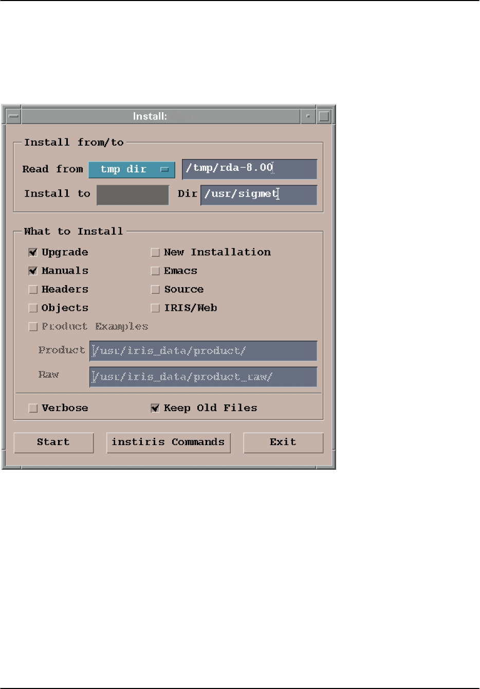
A.6.6 Using the install utility
The install utility is shown below. The utility allows you to select the source for the files and the
system on which you want to do the installation. You can also select which files you want to
install. The menu fields are described in the following sections.
rvp8
rvp8
Install from/to, Read from- select whether you are installing from a temporary directory or a
CDROM. Type-in the directory that contains your install files. In the example, this is
/tmp/rda–8.00
Install from/to, Install to- Type-in the network node name of your RVP8 or RCP8. If you are
unsure, look at the very top of the menu. In the example, the nodename is rvp8. Enter the
directory anchor point for the install– typically this is /usr/sigmet (the factory default).
What to install- click the Upgrade button and any special packages that you may want to
install. In the case of an installation from a local directory, be sure that you have downloaded the
corresponding files from SIGMET. For a minimal installation you would select only the
Upgrade option. If you are installing from CDROM then you have the manuals there so also
select Manuals to get the most up to date documentation.

Software Installation
RVP8 User’s Manual
April 2003
A–30
Keep old files- should be clicked-in, unless the release notes specify otherwise.
When you have finished making your selections, then click Start to do the install. A text status
screen will show you the progress of the install. If you had clicked Verbose, then this status
screen would show more detail.
install error message that applications are still running
The most common problem in running install is that SIGMET application processes are still
running on the system. You will get a message complaining that there are processes still running.
Perhaps you forgot to do a “killall rvp8” or have other utilities running. Check Section A.6.5
for instructions on stopping SIGMET processes.
After all processes are stopped (a clean ps_iris), then click Start again.

Software Installation
RVP8 User’s Manual
April 2003
A–31
A.7 Network Basics
The RVP8 and RCP8 are generally delivered from SIGMET packaged as fully integrated Linux
based computers running the SIGMET RDA application software. Being Linux computers, they
have the ability to interface to a computer network- in fact, for normal operation in
communicating with host software running on a different computer, they must be connected to a
network. This chapter gives some helpful information for:
The default RVP8 or RCP8 configuration as delivered
How to change this default configuration
How to use the RVP8 and RCP8 in conjunction with other hosts on the network
A.7.1 Default Out Of The Box Configuration
When delivered as fully integrated Linux computers, the RVP8/RCP8 has two LAN interfaces.
These are designated as ETH0 and ETH1. The ETH0 interface is the only one that is enabled by
default. The ETH1 interface is available, but no enabled. Both of the LAN interfaces are RJ–45
style ports that accept a standard LAN twisted pair style cable. SIGMET recommends that CAT
5e or better cable be used for this connection.
On most systems there are two network connectors. Usually ETH0 is
the left one (looking at the back of the unit) next to the VGA connector.
Depending on the version of the motherboard, the LAN interfaces are both either 10/100 Mbps,
or 100/1000 Mbps. In both cases the interfaces will negociate to the highest speed allowed by
the device (often a hub or a switch) that they are connected to. To determine the style of
motherboard, look at the Model Number in the back corner of the motherboard. If it has a –Q
suffix, the LAN speeds are 10/100. If it has a –G2 suffix, the LAN speeds are 100/1000.
The IP address of the RVP8/RCP8 out of the box is 192.168.76.90 with subnet mask of
255.255.255.0. There is no default route nor DNS server configured. Thus the RVP8/RCP8
could be used immediately on network identified as 192.168.76.0.
The RVP8/RCP8 is configured with only a minimum number of network services running. This
implies a very conservative (safe) network security profile. The only service that is running is
the portmapper as this service is required by the SIGMET RDA application software. With a
very safe and conservative security policy such as this out of the box configuration, the RVP8
and RCP8 will be able to exist on the network and have no security concerns.

Software Installation
RVP8 User’s Manual
April 2003
A–32
A.7.2 Making Changes to Default Configuration
The one change that probably will be needed to the RVP8/RCP8 in almost every instance is to
change the default IP address of ETH0. This will of course allow you to use the RVP8/RCP8 on
a pre–existing computer network.
IP Address Configuration
To change the IP address, you must edit the file /etc/sysconfig/network_scripts/ifcfg–eth0. The
default version of this file will have about 10 lines and two of them of the format:
IPADDR=192.168.76.90
NETMASK=255.255.255.0
You may change the IPADDR to any valid address and if necessary, you should also change the
NETMASK. You should contact your network administrator for assistance in identifying
appropriate values for these lines. The other lines in the file require no change. It should be
noted that the RVP8/RCP8 requires the same IP address all the time, thus dynamic IP addressing
(such as DHCP) is not appropriate. After making the above changes to the ifcfg–eth0 file, you
should reboot to make the changes take effect.
If you wish to use the second LAN interface (ETH1), to configure this, you should create the file
ifcfg–eth1 in the /etc/sysconfig/network–scripts directory. The easiest say to do this is to just
copy the ifcfg–eth0 file to ifcfg–eth1. Then edit the ifcfg–eth1 file and change the
“DEVICE=eth0” line to read “DEVICE=eth1”, and change the IPADDR and NETMASK
lines as appropriate. Again, contact your network administrator for assistance in identifying the
appropriate values. In addition, you must edit the file /etc/modules.conf and for –Q series
motherboards, add to the end a line reading “alias eth1 eepro100”. For –G2 series
motherboards, add a line reading “alias eth1 e1000”. Then reboot to make these changes
take effect.
Default Routes and Hostname
In the default configuration, the RVP8/RCP8 can communicate with any other computer on the
local network, but is not configured to communicate with computers on other networks.
To allow such communication, edit the file /etc/sysconfig/network and add the line
“GATEWAY=192.168.76.1”. Of course substitute the IP address of your default gateway for the
192.168.76.1 value in this example. You system administrator can provide you with the correct
value.
Also in the same file a line such as “HOSTNAME= localhost.localdomain” exists in this
file. You can substitute a new hostname for the “localhost.localdomain”. You must
also edit the file /etc/hosts and add to this a line that first lists the IP address of your ETH0, then
lists your hostname exactly as it appears in the /etc/sysconfig/network file.
After making any changes to default routes and/or hostnames, you must reboot your computer
before they will take effect.

Software Installation
RVP8 User’s Manual
April 2003
A–33
Hosts and DNS
In the out of the box configuration, the RVP8/RCP8 can communicate with other computers on
the network, but only by using IP Addresses. If you want to communicate with other computers
using Hostnames, you must configure either a hosts table or DNS. Generally, a small network of
only a few computers uses a hosts table, while large networks generally use DNS. It is up to you
to decide which method is appropriate and again, your network administrator can provide
advice.
To configure hostnames using a host table, this is done by editing the /etc/hosts files and adding
lines that default the IP address of a host and its hostname. For example, a line such as:
met_server
would allow you to communicate with the host “met_server” using its hostname rather than its
IP address.
For DNS, you do not need to enter individual hostnames into a local host file, but it is assumed
that all of the hostnames and IP addresses are stored on a central DNS server. All you need to do
is to install a pointer to this server computer and then you can communicate using hostnames to
any of the computers in the list on the DNS server. To enable DNS, edit the file /etc/resolv.conf
and add a line such as:
nameserver 192.168.76.99
Of course substitute the IP address of your DNS server for the “192.168.76.99” listed above,
and again, your network administrator can provide you with the appropriate information.
Time Zones Configuration
By default, the system clock and time zone of your RVP8/RCP8 are set to UTC (Universal Time
– also called Greenwich time). If you wish to change your time to be reported as local time
rather than UTC, you can use the “timeconfig” utility to do this. When using timeconfig, you
need to select your local time zone from the list provided. And also you need to select if the
BIOS stores time in UTC. SIGMET recommends using BIOS time in UTC because this is more
standard. But you are free to choose any timezone (or UTC) from the list provided. You should
reboot your computer after making any change using “timeconfig”.
Time Synchronization using NTP
Because the data generated by the RVP8/RCP8 is time stamped, it is often useful to have an
automated way of keeping the system clock accurate. Using the Network Time Protocol (NTP)
is an effective and easy way of doing this.
To use NTP, you must have an NTP server on your network. Often this is a single system where
your network administrator oversees keeping the clock accurate so other computers can sync
their clocks to it. There are also automatic NTP servers that sync their clock to GPS (satellite
based time) and then other computers can sync to this.
Assuming you have such an NTP server available on your network, to setup NTP on the
RVP8/RCP8, you must first execute the command “chkconfig –service ntp on”. Next
you must edit the file /etc/ntp.conf and find add the line “server 192.168.76.98”. Of

Software Installation
RVP8 User’s Manual
April 2003
A–34
course substitute the IP address of your NTP server for 192.168.76.98 in this example. There
are many other lines in the /etc/ntp.conf file, but these are not used for normal configuration and
must be left with a comment symbol “#” prefixing them. Generally, you should only have one
line without a comment symbol, and that is the “server ...” line defined above. Next you
should edit “or create” the file /etc/ntp/step–tickers. In this file put only the IP address of your
NTP server. There should be nothing before or after the IP address, and it should be the only
line in the file. The /etc/ntp/step–tickers file causes your computer to sync its time abruptly to
the NTP servers time while your computer is booting, and the /etc/ntp.conf file causes your
computer to periodically compare its time to the NTP server and make small adjustments as
needed. Once again, you must reboot your computer before the above changes take effect.
Adding Network Services
If more network services are required (such as telnet, rlogin, ftp, ...) these can be optionally
enabled. Before enabling such network services, it is advisable to review these decisions with
your network administrator to make sure that the network safety of the RVP8/RCP8 is not
compromised. The easiest way to enable these services is by using the “ntsysv” utility. When
running this utility, you are presented with a list of many system services (not only network
services). Services that are currently enabled have a star “*” in front of them. You can either
enable or disable a service by scrolling to it and then pressing the space bar. This will toggle the
star and thus if the service is enabled.
Again, it is recommended that you discuss with your system administrator before making any
changes because such changes could have a profound effect on the security of your system.
After making any changes, you should reboot your computer before they will take effect.
One such services that you might want to consider enabling is telnet. Telnet allows your to login
to your RVP8/RCP8 from another computer on the network and is often convenient. Telnet uses
a user name and password for security authentication.

Packaging
RVP8 User’s Manual
April 2003
B–1
B. RVP8/RCP8 Packaging
A standard RVP8/RCP8 processor consists of three separate units:
Main Chassis Section B.1 RVP8 and RCP8
Connector Panel Section B.2 RVP8 and RCP8
IFD (IF Digitizer) Section B.3 RVP8 Only
Because of the similarity of the packaging for the RVP8 and RCP8, both units are described
here.
The main chassis and connector panel are located in a rack within 100m of the IFD. Typically
the main chassis interfaces to a host computer via 100 BaseT Ethernet. For the RVP8, the IFD
receiver module resides in the radar cabinet.
This section describes the general features of the packaging and the electrical specifications and
cabling of these units. Please read CAREFULLY the following warnings before you apply
power to your system.
WARNING: The Main Chassis power supply modules are NOT auto ranging. These must
be set by a switch on each module for either 115/230 VAC 60/50 Hz. Verify these before
applying power to the system. See Section B.1.3.
WARNING: Turn off power to the main chassis before installing or removing any PCI
boards. For safety, the line cord should be disconnected before opening either the IFD
module or main chassis.
Important: The circuit boards contain many static sensitive components. Do not handle
the boards or open the IFD module unless a properly grounded wrist strap is worn.

Packaging
RVP8 User’s Manual
April 2003
B–2
B.1 Main Chassis General Description
SIGMET’s standard main chassis is a 4U rackmount/table top enclosure (43.2 wide x 43.2 long
x 17.8 cm high) or (17 wide x 17 long x 7.00 inch high) which fits a standard 19-inch EIA
rack. The system comes standard with hot–swap redundant power supplies. The chassis may be
equipped with either a mother board or a single-board computer depending on how the unit was
purchased. The chassis is shown in the following figures.
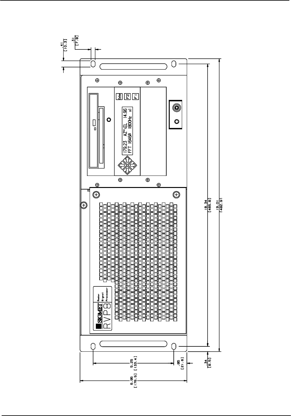
Front View Figure B–1
Rear View Figure B–2
Side view Figure B–3
Internal Wiring Figure B–4
The front of the unit has a plasma matrix display that is used for status information. There is also
a CDRW drive (for software installation and backup) and in most cases, a floppy drive as well
(for configuration backup).
Two fans are mounted behind the door on the front of the enclosure. These draw ambient air in
to the unit. The air flows through the unit and exits the rear. Do not block the slots or the exhaust
grills on the fans. Check airflow now and then, and also check the board and fan screen for dust
accumulation. If necessary, excessive dust accumulations on the board can be cleaned at a
properly equipped static-free workstation with “canned air” or Chemtronics TF-Plus solvent,
which can be purchased through electronics distributors.
The boards should be left in the chassis whenever the unit is shipped. This minimizes handling
and static risk. Save the original packing provided for shipment.
Important: Prior to shipment, contact support@sigmet.com to obtain a returned materials
authorization (RMA) and to coordinate the shipping.
A table top unit can be converted for rack mount by simply installing rack mount ears. The rack
ears are installed with #8-32 flat head screws. It is strongly recommended that the rack mount
slide brackets supplied with the unit should be installed in the rack for additional structural
support.
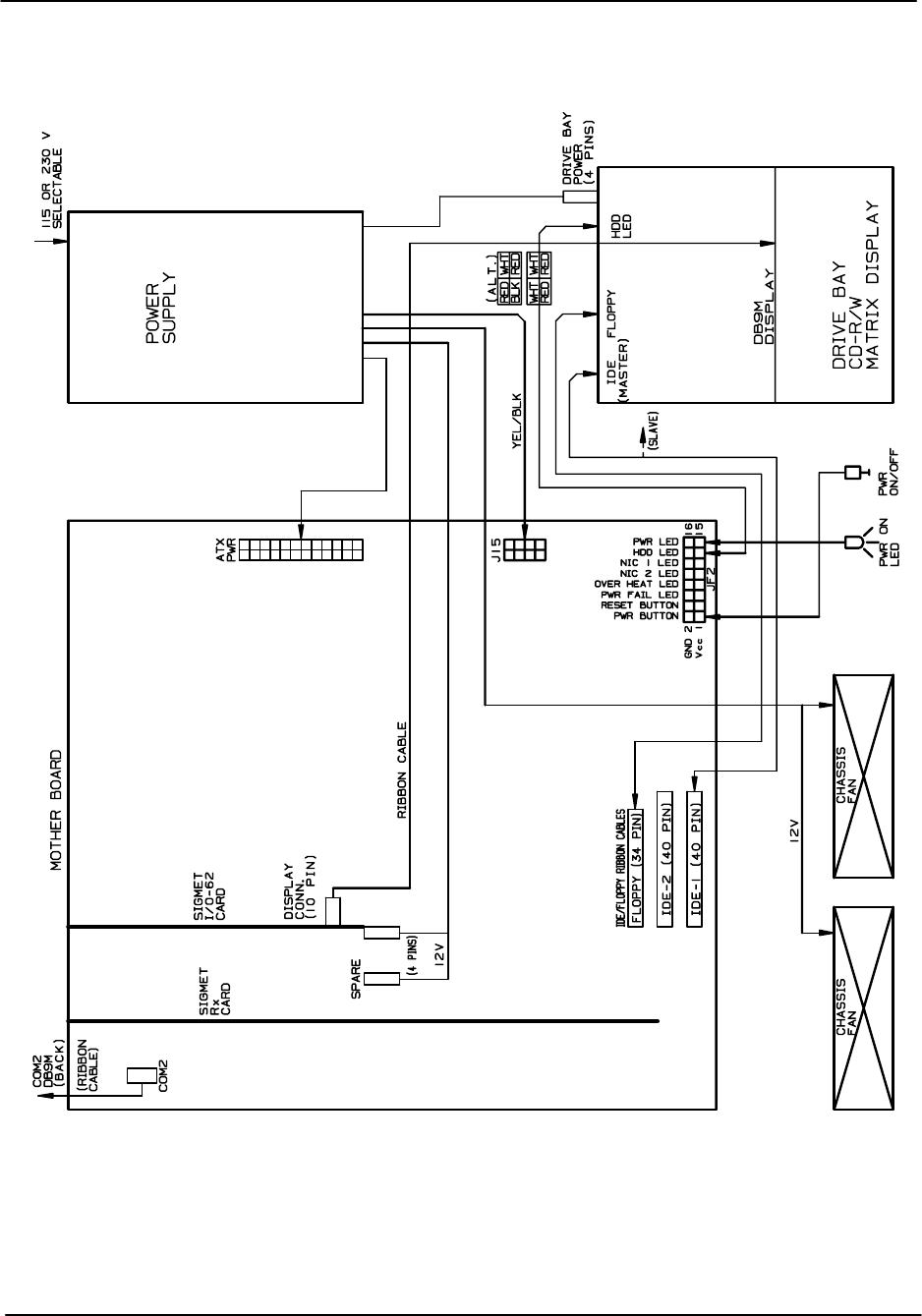
The internal cabling diagram in Figure B–4 shows how the various disk drives, power supplies,
etc. are connected within the standard Main Chassis. A mother board example is shown. Use this
as a guide if you have to replace internal components.
The remainder of this section describes the front and rear panel of the Main Chassis.
Packaging
RVP8 User’s Manual
April 2003
B–3
Figure B–1: Main Chassis- Front Panel
Packaging
RVP8 User’s Manual
April 2003
B–4
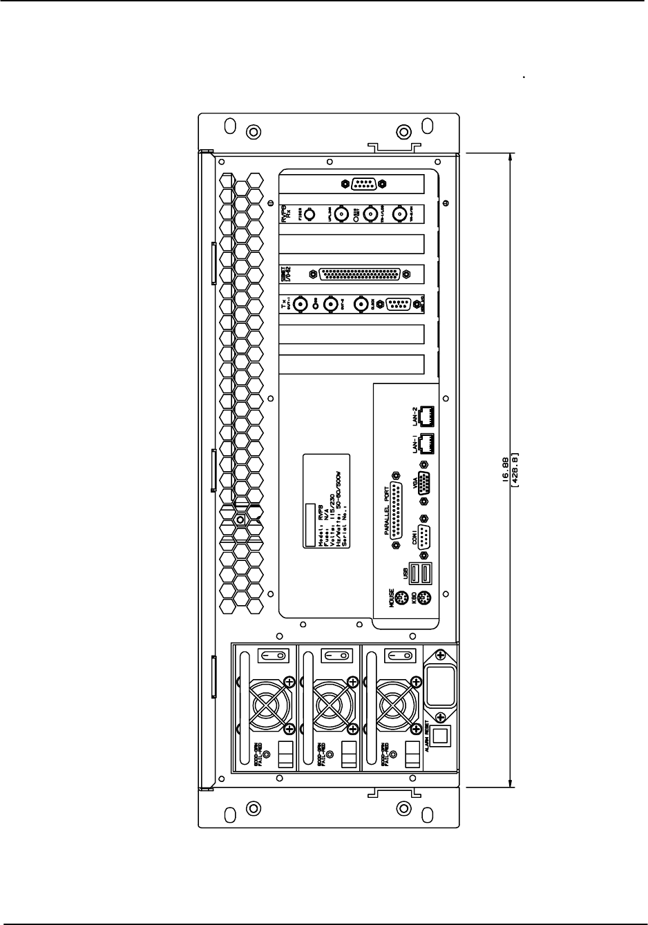
Figure B–2: Main Chassis- Back Panel
Packaging
RVP8 User’s Manual
April 2003
B–5
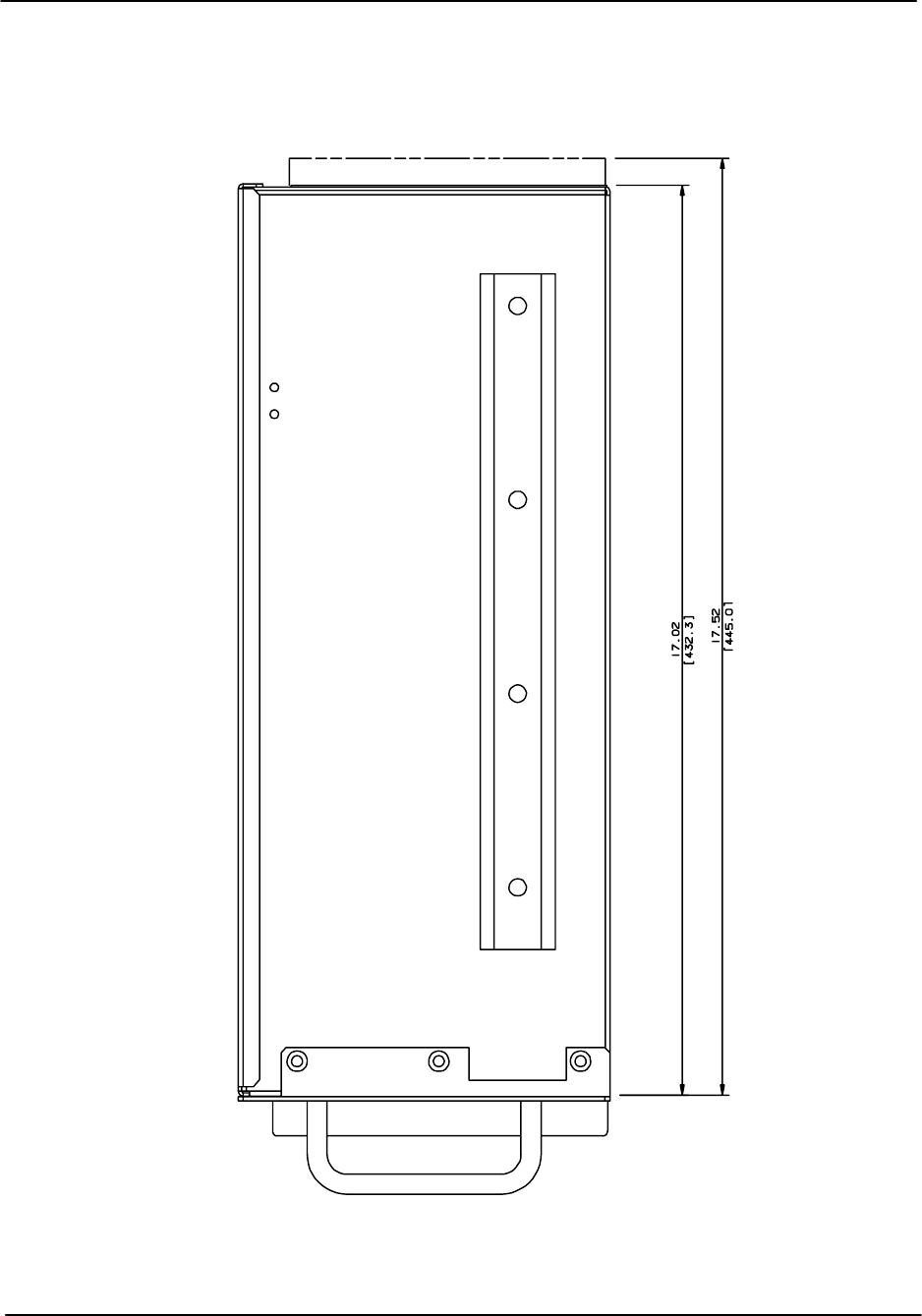
Figure B–3: Main Chassis- Right Side View
Front
Back
Top
Packaging
RVP8 User’s Manual
April 2003
B–6
Figure B–4: Main Chassis Internal Cabling
Packaging
RVP8 User’s Manual
April 2003
B–7
B.1.1 Main Chassis Front Panel
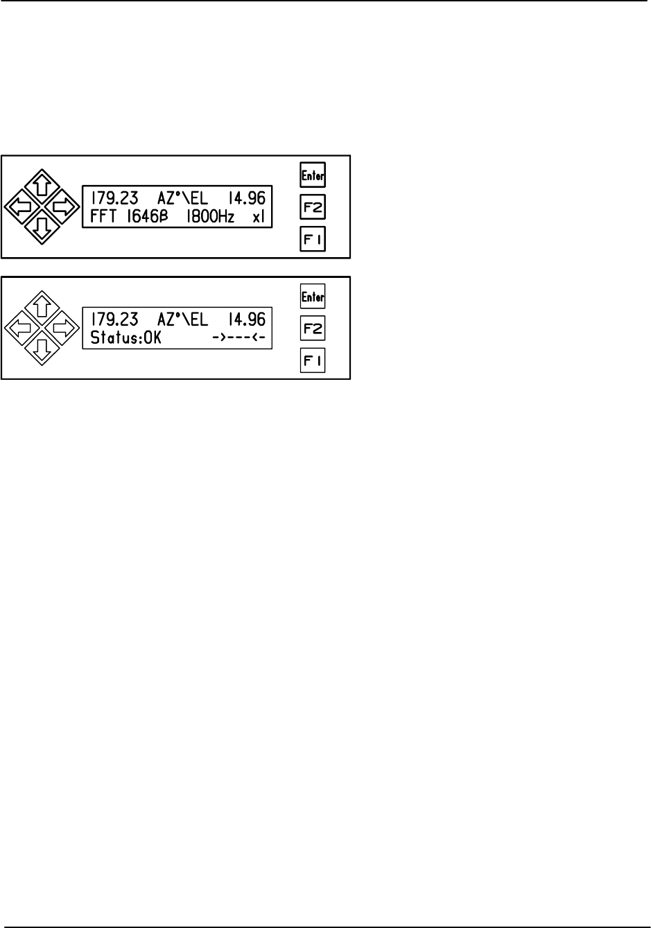
The front panel is shown in Figure B–1. The front panel matrix plasma display is typically
connected internally by a ribbon cable to either an I/O-62 card or an RVP8/Rx card. The display
is used to show status and power-up test results. Power–up features are described in detail in
Section 2.3.5. The function keys beside the display are not currently used.
RVP8 Receiver/Signal Processor
RCP8 Radar Control Processor
In addition, the CDRW and the floppy drive are located on the front panel. The various activity
lights are for the CDRW (yellow), floppy drive (small green) and the hard disk drive (large red).
The cabling diagram shows how to connect the activity lights. At the lower right of the unit is a
power on/off switch and a green LED to indicate that power is on.

Packaging
RVP8 User’s Manual
April 2003
B–8
B.1.2 Main Chassis Back Panel
Figure B–2 shows an example of the main chassis back panel for the case of a motherboard
system. There are three main sections to the Main Chassis back panel:
Power section- on the left (looking from the rear) with the power entry module,
alarm reset and three redundant hot-swap power supplies.
PC I/O section- in the lower center with connectors for keyboard, mouse,
monitor, network, etc. This is for a mother board example.
PCI card section- on the right (looking from the rear) with standard PCI slots for
the RVP8/RCP8 circuit cards as well as other standard commercial PCI cards that
may be used (e.g., a four port serial card).
Note that depending on whether your system is using a mother board or single-board computer
(SBC), the appearance of these sections may be different, but the functions are the same. These
sections are described in detail in the sections below.

Packaging
RVP8 User’s Manual
April 2003
B–9
B.1.3 Main Chassis Back Panel Power Section
WARNING: The Main Chassis power supply modules are NOT auto ranging. These must
be set by a switch on each module for either 115/230 VAC 60/50 Hz. Verify these per the
procedure below, before applying power to the system.
The Main Chassis back panel is equipped with a modular AC power entry device. There are
three hot-swap redundant power supply modules in the system. The procedure for
setting/verifying the voltage on each one is as follows:
The unit should be powered-off. This can be assured by simply not connecting the
power input cord.
Remove the top power supply module by shifting the black release button to the
right.
Use the handle to pull the module out.
Check the red power selector switch on the right side (rear) of the module and set
it as appropriate to your line voltage (115/230).
Re–insert the module and push the chrome handle down. This switches the
module in the on “1” position.
Repeat this procedure for the middle and lower modules (the order is not
critical)).
When the system is switched–on, the LED on each module shows green to indicate that it is
functioning properly. A red light indicates a failure. There is an audio “buzzer” alarm in the
event that a power module is turned-off, removed or fails.
Note: The red button next to the power entry module will reset the “buzzer” alarm.
The system will function if there is failure of any one power module, but is not rated to function
with only one module, i.e., if two modules fail. Each power module is equipped with internal
protection for over-temperature and over-current. In the event that the protection is triggered, the
module LED will show red. It can be reset by removing the module for a minute and then
inserting the module back into the system. It is best to do this with power–off to the module.
Note: If a power module is switched on, but the LED indicator is red, then it is not
functioning. The reset procedure is to turn the power off on the failed module, remove it
for one minute and then re-insert it and power it back on.
Packaging
RVP8 User’s Manual
April 2003
B–10
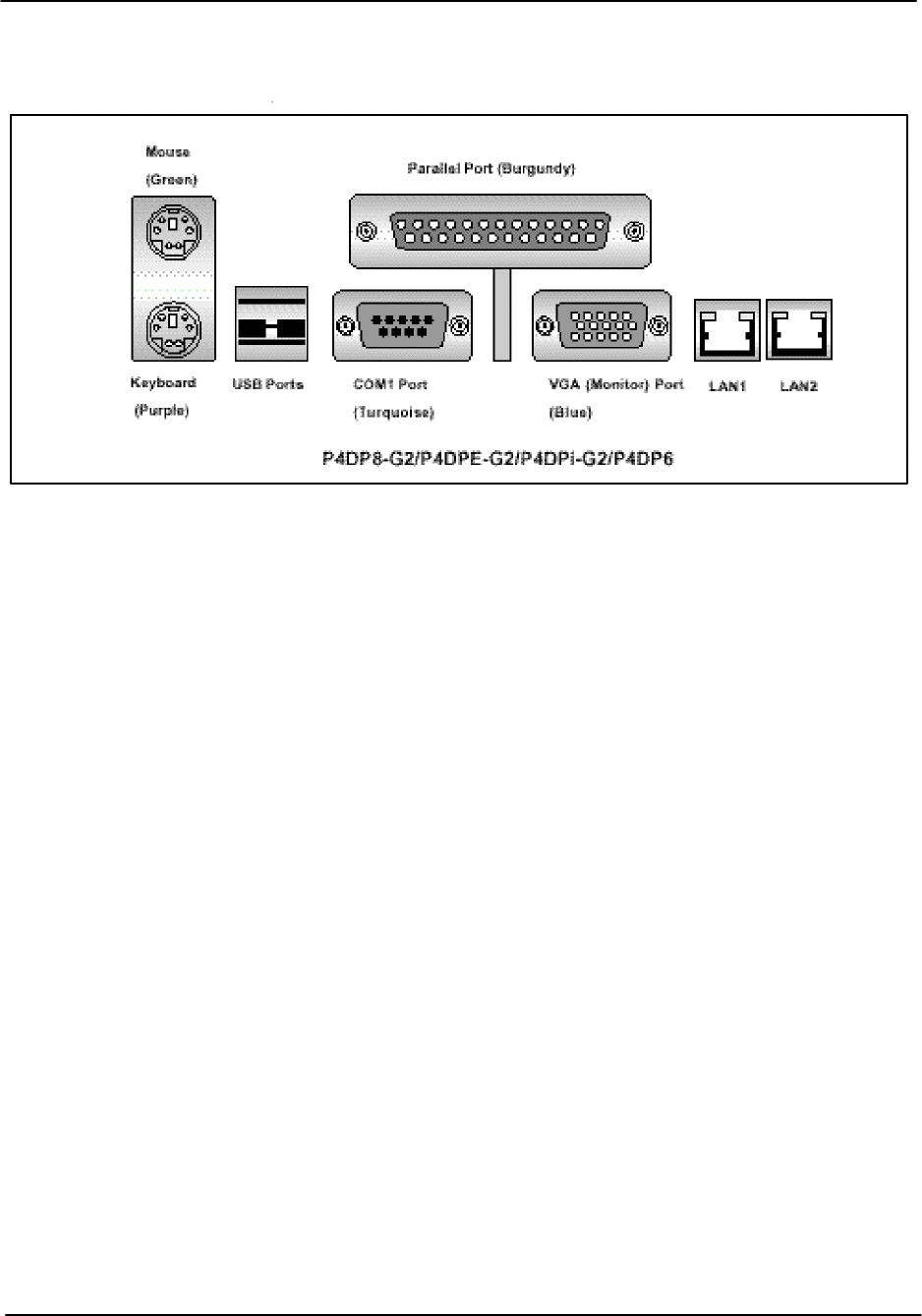
B.1.4 Main Chassis Back Panel PC I/O Section
The PC I/O section shown above is where you make all of your standard PC connections. Note
pins (male) are indicated by filled black circles while sockets (female) are indicated by open
circles.
A standard keyboard and mouse are provided with the unit. VGA monitor is supplied by the
customer or ordered as an option from SIGMET.
Note that LAN 1 and LAN 2 are standard RJ45 connectors. For the –G2 style mother boards the
LAN port speed is 100/1000 BaseT. For the –Q they are 10/100 BaseT.
The keyboard and mouse are standard PS/2. You can use an adapter to plug a USB mouse into
the circular mouse connector.
COM1 is the DBM9 connector. COM2 is typically installed as a separate DBM9 connector in the
PCI section.
Packaging
RVP8 User’s Manual
April 2003
B–11
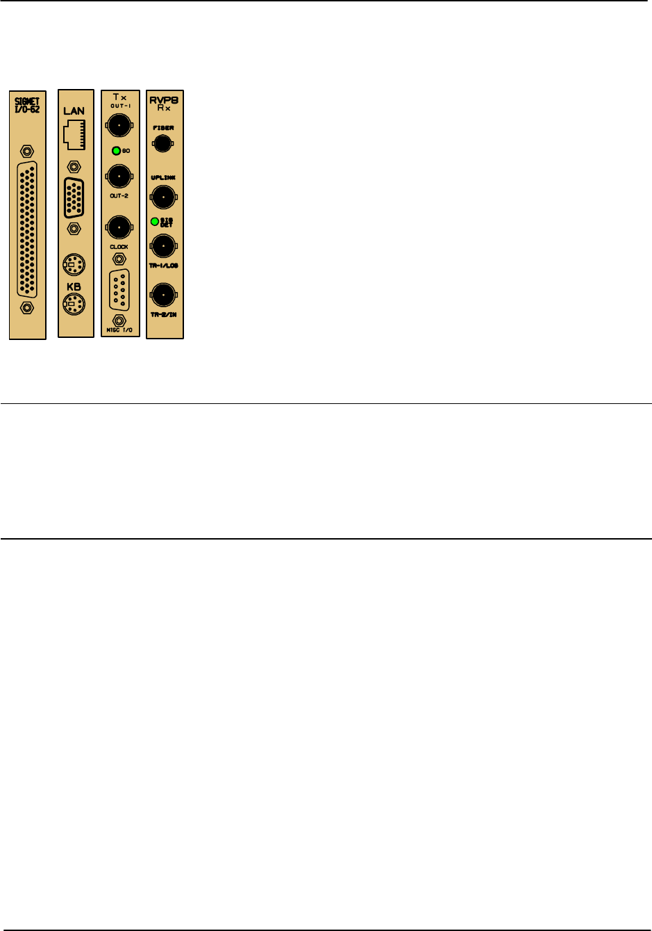
B.1.5 Main Chassis Back Panel PCI Card Section
The PCI cards are installed vertically on the right of the chassis
(looking from the back). Since there are many different
RVP8/RCP8 configuration options that can be ordered, there is
quite a bit of variability in what PCI cards are installed. For the
RCP8, however, there is typically only an I/O-62 PCI Card.
Note that COM2 is typically installed as a connector in the PCI
section.
PCI
Card Used on Vendor Functions
I/O –62 RVP8 RCP8 SIGMET I/O to radar system control and monitoring
RVP8/Rx RVP8 only SIGMET Uplink/Downlink IFD connections. Two triggers.
RVP8/Tx RVP8 only SIGMET Two waveform outputs, clock output/input, 4 RS422 lines
HPIB RVP8 RCP8 Market HPIB control for signal generator or other test equipment
COM2 RVP8 RCP8 Market RS232C used for COM2.
Please see Section 2.3.3 of the RVP8 User’s Manual for a description of the connectors on the
RVP8 PCI cards. The I/O-62 is used on both the RVP8 and RCP8. It is described in the next
sections, along with the standard connector panels for the RVP8 and RCP8.

Packaging
RVP8 User’s Manual
April 2003
B–12
B.2 I/O-62 and Connector Panel
Figures B–5 and B–6 show the I/0-62 Connector Panel for the RVP8 and RCP8. This is
typically mounted on the same rack as the Main Chassis. A 1:1 62–position cable (standard 1.8
m/6 foot) connects the connector panel to the I/O-62. As shown in the figures, the cable can be
connected to either the front or the back of the panel so that the cable run can be optimized. In
most cases, it is recommended to connect the cable to the back of the panel to minimize the risk
of physical damage to the cable.
The panel is electrically the same for both the RVP8 and RCP8.Indeed the circuit board is
identical. However, the panel labelling and the softplane configurations are different.
The pin assignments to the various connectors are described in Tables B–1 to B–14 located at
the end of this section. The tables show the basic electrical properties of each pin and the default
signal assignment (if any) that is made in the factory softplane.conf file. The softplane approach
provides a great deal of flexibility in assigning the I/O to the panel.
The I/O–62 PCI card provides forty multi–protocol digital interface lines at its 62–pin faceplate
connector. These lines are grouped into five independent and identical blocks, each of which
contains eight lines. Moreover, each of these blocks of eight lines can be further divided into
four line pairs.
Each block of I/O lines can operate in one of the following modes:
As eight TTL/CMOS single–ended outputs
As eight TTL/CMOS single–ended inputs
As N RS–422 differential transmitters or receivers, and (8–2N) TTL/CMOS
single–ended inputs.
The assignment of electrical levels and signal directions are all made in the ’softplane.conf’ file.
Users do not have to worry about how to configure each block of lines because inconsistent
signal assignments will be checked and reported when the file is loaded.
All forty I/O–62 digital lines are individually protected against both overvoltage and electrostatic
discharge (ESD). You may safely apply voltages between –27V and +27V to any line regardless
of whether it is configured for an input or output. Likewise, external ESD pulses of 15KV
(Human body model) will be safely shunted to ground at the 62–pin connector point of entry.
This wide voltage tolerance effectively makes the TTL/CMOS inputs function as wide range
comparators with a 2.5V logic threshold. These inputs could be connected directly to a 24V
panel bulb, for example, in order to monitor its On/Off status. Note that the line protection
circuitry has a side effect of raising the output impedance of the TTL/CMOS drivers to
approximately 120–Ohms. This should not cause any trouble unless the signal is heavily
terminated at the receiving end. The RS–422 drivers are not affected by the line protection, and
have the standard very low output impedance.
The I/O–62 provides a variety of terminations for its digital I/O lines. The TTL/CMOS signals
can optionally be pulled either to GND or to +5V through a 2.2K–Ohm resistor. Similarly, the
RS–422 linepairs can optionally be terminated with a 100–Ohm resistor across each pair.

Packaging
RVP8 User’s Manual
April 2003
B–13
There are a few additional constraints that should be kept in mind when assigning electrical
signals to a block of eight I/O–62 lines. These are:
When TTL/CMOS pull-up/pull-down resistors are enabled, they are applied to
the entire group of eight lines. This is somewhat inconsistent with using some of
those same lines as RS–422.
Similarly, when RS–422 terminators are enabled, they are applied to all four line
pairs. This is completely inconsistent with using some of those same lines as
TTL/CMOS.
Thus, if line termination is required, it is usually necessary to split the TTL/CMOS and RS–422
functions so that both do not appear within the same block of eight lines.
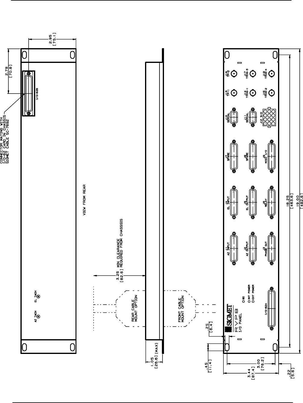
Packaging
RVP8 User’s Manual
April 2003
B–14
Figure B–5: RVP8 I/O-62 Connector Panel
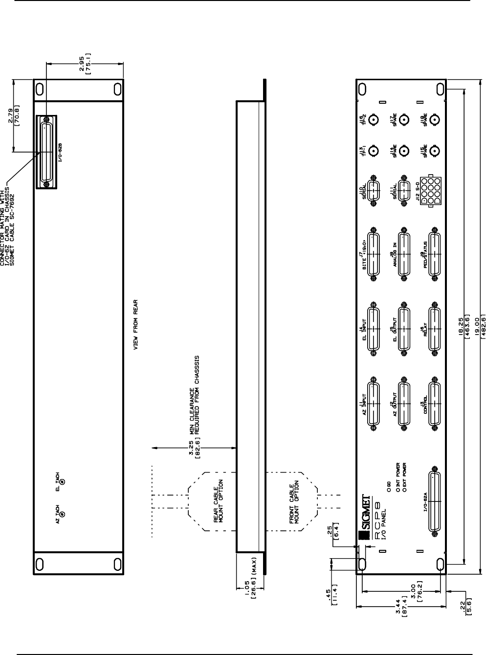
Packaging
RVP8 User’s Manual
April 2003
B–15
Figure B–6: RCP8 I/O-62 Connector Panel

Packaging
RVP8 User’s Manual
April 2003
B–16
Table B–1: J1 “AZ INPUT”
Pin Electrical Specification RVP8 Signal Name RCP8 Signal Name
1 TTL sPedAZ[0] sPedAZ[0]
2 TTL sPedAZ[1] sPedAZ[1]
3 TTL sPedAZ[2] sPedAZ[2]
4 TTL sPedAZ[3] sPedAZ[3]
5 TTL sPedAZ[4] sPedAZ[4]
6 TTL sPedAZ[5] sPedAZ[5]
7 TTL sPedAZ[6] sPedAZ[6]
8 TTL sPedAZ[7] sPedAZ[7]
9 TTL sPedAZ[8] sPedAZ[8]
10 TTL sPedAZ[9] sPedAZ[9]
11 TTL sPedAZ[10] sPedAZ[10]
12 TTL sPedAZ[11] sPedAZ[11]
13 TTL sPedAZ[12] sPedAZ[12]
14 TTL sPedAZ[13] sPedAZ[13]
15 TTL sPedAZ[14] sPedAZ[14]
16 TTL sPedAZ[15] sPedAZ[15]
17 TTL
18 TTL
19 TTL
20 TTL
21 GND
22 GND
23 GND
24 GND
25 GND

Packaging
RVP8 User’s Manual
April 2003
B–17
Table B–2: J2 “AZ OUTPUT”
Pin Electrical Specification RVP8 Signal Name RCP8 Signal Name
1 TTL cPedAZ[0] cPedAZ[0]
2 TTL cPedAZ[1] cPedAZ[1]
3 TTL cPedAZ[2] cPedAZ[2]
4 TTL cPedAZ[3] cPedAZ[3]
5 TTL cPedAZ[4] cPedAZ[4]
6 TTL cPedAZ[5] cPedAZ[5]
7 TTL cPedAZ[6] cPedAZ[6]
8 TTL cPedAZ[7] cPedAZ[7]
9 TTL cPedAZ[8] cPedAZ[8]
10 TTL cPedAZ[9] cPedAZ[9]
11 TTL cPedAZ[10] cPedAZ[10]
12 TTL cPedAZ[11] cPedAZ[11]
13 TTL cPedAZ[12] cPedAZ[12]
14 TTL cPedAZ[13] cPedAZ[13]
15 TTL cPedAZ[14] cPedAZ[14]
16 TTL cPedAZ[15] cPedAZ[15]
17 TTL
18 TTL
19 TTL
20 TTL
21 GND
22 GND
23 GND
24 GND
25 GND

Packaging
RVP8 User’s Manual
April 2003
B–18
Table B–3: J3 RVP8: “PHASE OUT”; RCP8 “CONTROL”
Pin Electrical Specification RVP8 Signal Name RCP8 Signal Name
1
2 Configurable
3
g
I/O–62
4Digital
5Lines
6
7
8
9 RS422+ RS422+[0]
10 RS422+ RS422+[1]
11 GND
12 GND
13 GND
14
15 Configurable
16
g
I/O–62
17 Digital
18 Lines
19
20
21
22 RS422– RS422–[0]
23 RS422– RS422–[1]
24 GND
25 GND

Packaging
RVP8 User’s Manual
April 2003
B–19
Table B–4: J4 “EL INPUT”
Pin Electrical Specification RVP8 Signal Name RCP8 Signal Name
1 TTL sPedEL[0] sPedEL[0]
2 TTL sPedEL[1] sPedEL[1]
3 TTL sPedEL[2] sPedEL[2]
4 TTL sPedEL[3] sPedEL[3]
5 TTL sPedEL[4] sPedEL[4]
6 TTL sPedEL[5] sPedEL[5]
7 TTL sPedEL[6] sPedEL[6]
8 TTL sPedEL[7] sPedEL[7]
9 TTL sPedEL[8] sPedEL[8]
10 TTL sPedEL[9] sPedEL[9]
11 TTL sPedEL[10] sPedEL[10]
12 TTL sPedEL[11] sPedEL[11]
13 TTL sPedEL[12] sPedEL[12]
14 TTL sPedEL[13] sPedEL[13]
15 TTL sPedEL[14] sPedEL[14]
16 TTL sPedEL[15] sPedEL[15]
17 TTL
18 TTL
19 TTL
20 TTL
21 GND
22 GND
23 GND
24 GND
25 GND

Packaging
RVP8 User’s Manual
April 2003
B–20
Table B–5: J5 “EL OUTPUT”
Pin Electrical Specification RVP8 Signal Name RCP8 Signal Name
Pin Electrical Specification RVP8 Signal Name RCP8 Signal Name
1 TTL cPedEL[0] cPedEL[0]
2 TTL cPedEL[1] cPedEL[1]
3 TTL cPedEL[2] cPedEL[2]
4 TTL cPedEL[3] cPedEL[3]
5 TTL cPedEL[4] cPedEL[4]
6 TTL cPedEL[5] cPedEL[5]
7 TTL cPedEL[6] cPedEL[6]
8 TTL cPedEL[7] cPedEL[7]
9 TTL cPedEL[8] cPedEL[8]
10 TTL cPedEL[9] cPedEL[9]
11 TTL cPedEL[10] cPedEL[10]
12 TTL cPedEL[11] cPedEL[11]
13 TTL cPedEL[12] cPedEL[12]
14 TTL cPedEL[13] cPedEL[13]
15 TTL cPedEL[14] cPedEL[14]
16 TTL cPedEL[15] cPedEL[15]
17 TTL
18 TTL
19 TTL
20 TTL
21 GND
22 GND
23 GND
24 GND
25 GND

Packaging
RVP8 User’s Manual
April 2003
B–21
Table B–6: J6 “RELAY”
Pin Electrical
Specification RVP8 Signal Name RCP8 Signal Name
1Relay K1: CT Internal Relay Center Contact
2Relay K1: NO Internal Relay Normally Open cPWidth[0]
3Relay K1: NC Internal Relay Normally Closed
4 Relay K2: CT Internal Relay Center Contact
5 Relay K2: NO Internal Relay Normally Open cPWidth[1]
6 Relay K2: NC Internal Relay Normally Closed
7Relay K3: CT Internal Relay Center Contact
8Relay K3: NO Internal Relay Normally Open
9Relay K3: NC Internal Relay Normally Closed
10 –––
11 GND
12 GND
13 GND
14 +12VDC External
15 +12VDC Relay
16 +12VDC
y
Control
17 +12VDC Power
18 +12V Unreg
19 Return14 External
20 +12V Return15 Relay
21 +12V Return16
y
Control
22 +12V Return17 Returns
23 –––
24 GND
25 GND
WARNING: To avoid possible damage to the connector panel, all external relays must be
equipped with diode protection against the back EMF generated when the external relay
coil is opened. Relays can be purchased with a diode installed or a diode can be added to
the relay across the coil supply and return.
Notes: Internal relays K1, K2, K3 on the connector panel are dry contacts:
CT Center contact
NO Normally open contact
NC Normally closed contact

Packaging
RVP8 User’s Manual
April 2003
B–22
Table B–7: J7: RVP8 “SPARE”; RCP8 “BITE 19:0”
Pin Electrical
Specification RVP8 Signal Name RCP8 Signal Name
1 TTL sAux[0]
2 TTL sAux[1]
3 TTL sAux[2]
4 TTL sAux[3]
5 TTL sAux[4]
6 TTL sAux[5]
7 TTL sAux[6]
8 TTL sAux[7]
9 TTL sAux[8]
10 TTL sAux[9]
11 TTL sAux[10]
12 TTL sAux[11]
13 TTL sAux[12]
14 TTL sAux[13]
15 TTL sAux[14]
16 TTL sAux[15]
17 TTL sAux[16]
18 TTL sAux[17]
19 TTL sAux[18]
20 TTL sAux[19]
21 GND
22 GND
23 GND
24 GND
25 GND

Packaging
RVP8 User’s Manual
April 2003
B–23
Table B–8: J8: RVP8 “SPARE”; RCP8 “ANALOG IN”
Pin Electrical Specification RVP8 Signal Name RCP8 Signal Name
1 Amux0+ Amux0+
2±20VDC Amux1+ Amux1+
3Differential Amux2+ Amux2+
4Analog Amux3+ Amux3+
5
g
Inputs Amux4+ Amux4+
6
p
Amux5+ Amux5+
7Positive Amux6+ Amux6+
8Side Amux7+ Amux7+
9Amux8+ Amux8+
10 Amux9+ Amux9+
11 GND
12 GND
13 GND
14 Amux0– Amux0–
15 ±20VDC Amux1– Amux1–
16 Differential Amux2– Amux2–
17 Analog Amux3– Amux3–
18
g
Inputs Amux4– Amux4–
19
p
Amux5– Amux5–
20 Negative Amux6– Amux6–
21 Side Amux7– Amux7–
22 Amux8– Amux8–
23 Amux9– Amux9–
24 GND
25 GND

Packaging
RVP8 User’s Manual
April 2003
B–24
Table B–9: J9 RVP8: “MISC I/O” ; RCP8: “PED/STATUS”
Pin Electrical Specification RVP8 Signal Name RCP8 Signal Name
1
2 Configurable
3
g
I/O–62
4Digital
5Lines
6
7
8±6 to ±70 VDC Input AzTach+
9±6 to ±70 VDC Input ElTach+
10 ±10 VDC Output AzDrive
11 GND
12 GND
13 GND
14
15 Configurable
16
g
I/O–62
17 Digital
18 Lines
19
20
21 ±6 to ±70 VDC Input AzTach–
22 ±6 to ±70 VDC Input ElTach–
23 ±10 VDC Output ElDrive
24 GND
25 GND
Note: Antenna pedestal tachometer inputs are adjusted by a potentiometer on the back of the
Connector Panel.

Packaging
RVP8 User’s Manual
April 2003
B–25
Table B–10: J10 “SERIAL”
Pin Electrical Specification Comment
1GND
2 RS232C Rx
3 RS232C Tx
4 –––
5 GND
6 –––
7 –––
8 –––
9–––
Table B–11: J11 “SERIAL”
Pin Electrical Specification Comment
1GND
2 RS232C Rx Channel 0
3 RS232C Tx Channel 0
4 RS232C Rx Channel 1
5 GND
6 RS232C Tx Channel 1
7 –12VDC @ 50mA max regulated Regulated power supply
8 +12VDC @ 50mA max Regulated power supply
9+5VDC @ 50mA max Regulated power supply

Packaging
RVP8 User’s Manual
April 2003
B–26
Table B–12: J12 “S–D”
Pin Electrical Specification RVP8 Signal Name RVP8 Signal Name
1 RefEL+ RefEL+
2Nominal 90V 60Hz RefEL– RefEL–
3Synchro Signals SyEL1 SyEL1
4
yg
SyEL2 SyEL2
5SyEL3 SyEL3
6 GND
7RefAZ+ RefAZ+
8Nominal 90V 60Hz RefAZ– RefAZ–
9Synchro Signals SyAZ1 SyAZ1
10
yg
SyAZ2 SyAZ2
11 SyAZ3 SyAZ3
12 GND

Packaging
RVP8 User’s Manual
April 2003
B–27
Table B–13: RVP8 BNC Connector Pin Assignments
Ref
Designator Label Electrical Specification Signal Name
J13 TP1 5V 75Ohm
J14 TRIG–1 12V 75Ohm Trigger[1]
J15 TRIG–2 12V 75Ohm Trigger[2]
J16 TP2 5V 75Ohm
J17 TRIG–3 12V 75Ohm Trigger[3]
J18 TRIG–4 12V 75Ohm Trigger[4]
Table B–14: RCP8 BNC Connector Pin Assignments
Ref
Designator Label Electrical Specification Signal
J13 TP1 5V 75Ohm
J14 SPARE
J15 SPARE
J16 TP2 5V 75Ohm
J17 SPARE
J18 SPARE

Packaging
RVP8 User’s Manual
April 2003
B–28
B.3 IFD Module (RVP8 Only)
The IFD module is a small metal box which can be mounted inside the receiver cabinet. The
IFD is shown in Figures B–7 and B–8. Cooling of the inside components is accomplished by
direct conduction to the case. It is desirable to place the module in an environment that allows
external convective cooling.
The IFD is equipped with its own auto ranging power supply (110 to 240 VAC 50/60 Hz) which
is mounted on the side of the IFD. On the other side of the IFD are two anti-aliasing filters.
These analog filters must be specified for the radar IF frequency. The filters have an 8 MHz
bandwidth centered about the IF frequency.
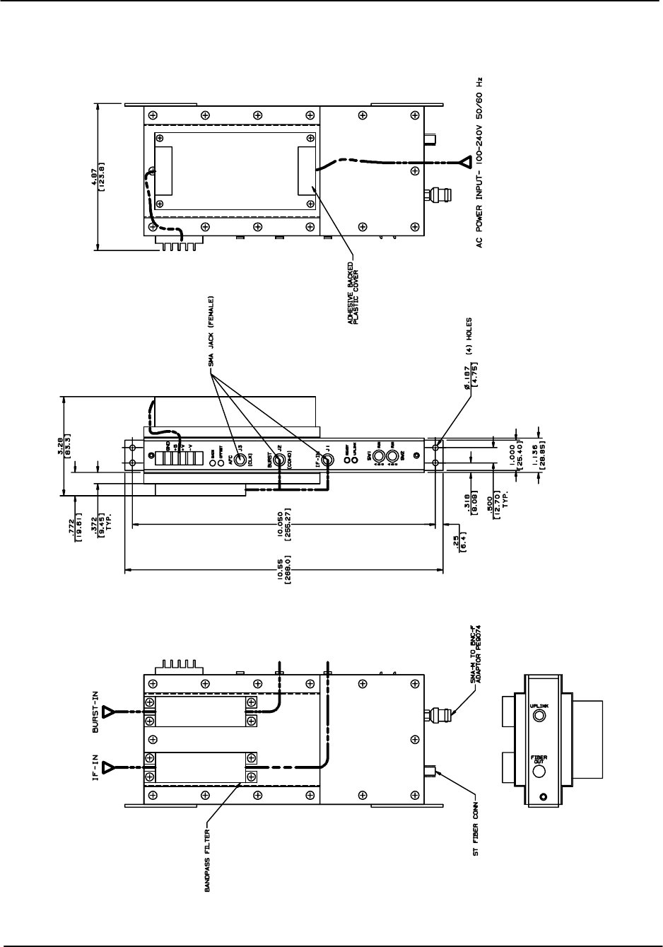
Packaging
RVP8 User’s Manual
April 2003
B–29
Figure B–7: RVP8/IFD Module
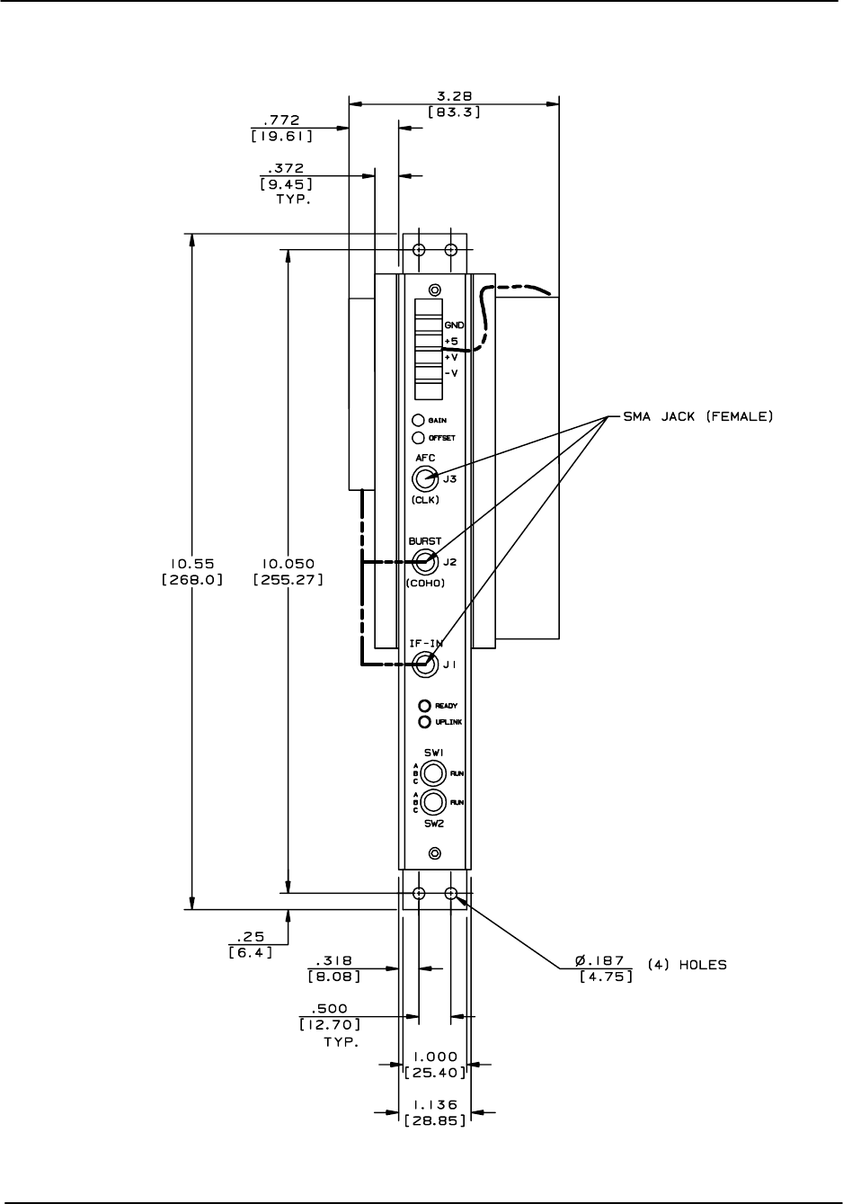
Packaging
RVP8 User’s Manual
April 2003
B–30
Figure B–8: IFD Front Panel
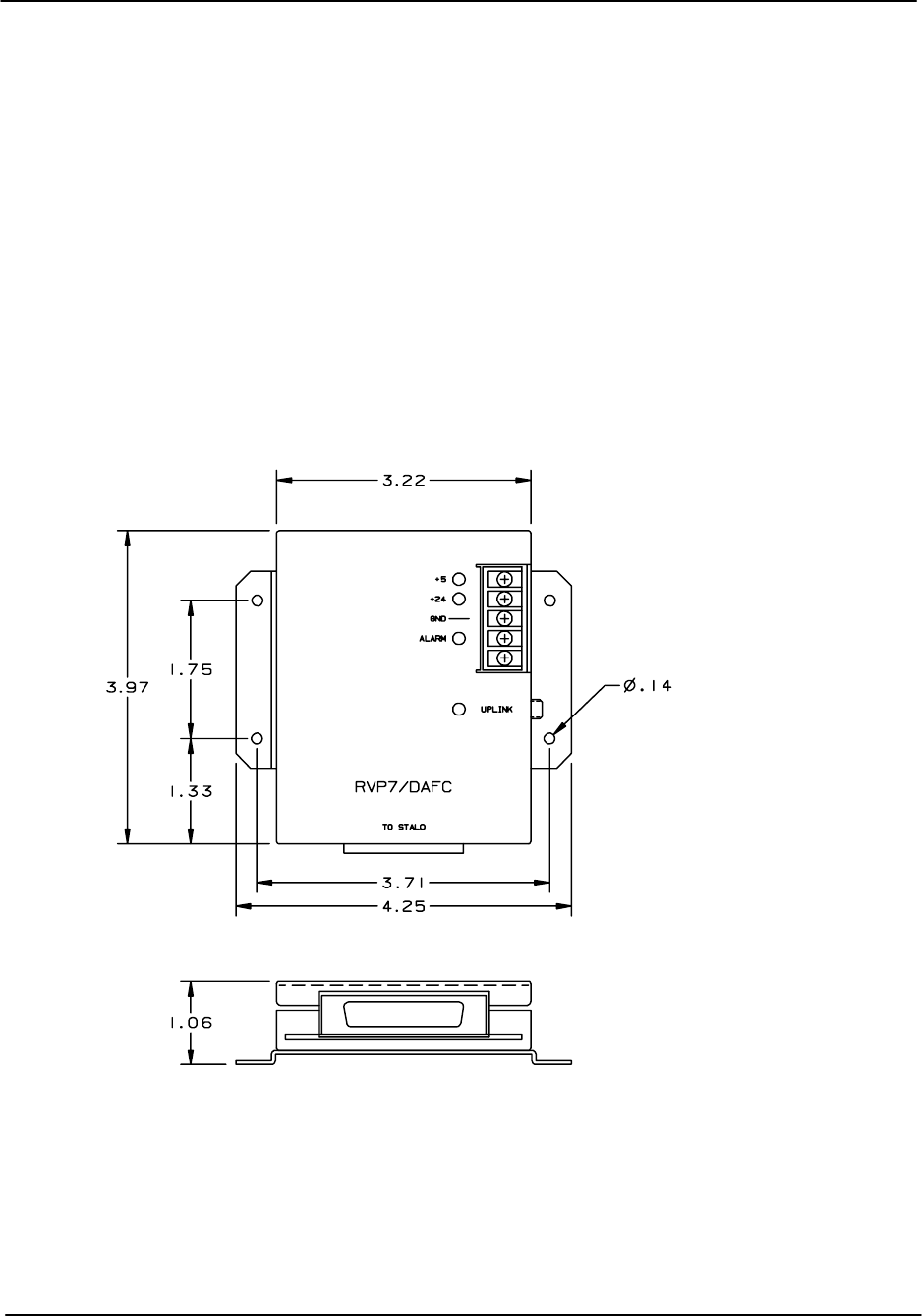
Packaging
RVP8 User’s Manual
April 2003
B–31
B.4 DAFC Module (RVP8 only)
The Digital AFC (DAFC) module is used on RVP8 for magnetron systems to interface to a
digitally controlled STALO. The DAFC “T’s” off the coax uplink cable. Power can be provided
by running discrete wires from the IFD. Note that +5 VDC is all that is required to run the
DAFC. If you want to supply the STALO power over the ribbon cable to the IFD, you can
connect the +24 VDC input to an appropriate power supply. Otherwise, you can power the
STALO directly.
The DAFC outputs up to 24 TTL lines to the STALO digital control/interface. Since these are
TTL, the DAFC should be mounted within 10 to 30cm of the STALO if possible. For details on
the DAFC, including pin assignment examples for some commercial STALO’s, please refer to
Section 2.4.
Figure B–9: View of DAFC Module

Clutter Filter Characteristics
RVP8 User’s Manual
April 2003
C–1
C. Clutter Filter Characteristics (DRAFT)
This draft appendix is based on the legacy RVP7 algorithms. The RVP8 will have some
additional features and may not contain some of the legacy features.
The RVP8 is shipped with a preprogrammed set of digital IIR (Infinite Impulse Response)
high-pass clutter filters. There are eight filters available. The filters are fourth-order Chebyshev,
and provide 40dB and 50dB stop band attenuation in seven different widths ranging from
approximately 2% to 14% of the Nyquist interval. Filter #0 is an all-pass filter, so that clutter
rejection can effectively be switched off.
The correct choice of filter for observing different weather conditions must be determined by
experiment. The filter with the highest rejection is not always the best choice, since the group
delay of signals in the transition band is greater for deeper filters. This effect introduces
dispersion in the Velocity/Time profile of the incoming signal. In general, try to use the
shallowest filter with the shortest impulse response that will do the job for the types of weather
and clutter that are typical at the radar site.
The processing algorithm for the IIR clutter filter is described in Chapter 5, as follows:
AnB0AnB1An1B2An2B3An3B4An4
C1An1C2An2C3An3C4An4
In this algorithm, the input time series An is processed to form a filtered output time series An,
and the B’s and C’s are filter coefficients. This appendix shows the magnitude response plots for
the set of filters supplied with the RVP8. The Doppler 40dB and 50dB clutter filter coefficients
are given in Tables C–1 and C–2.
Table C–1: Doppler 40dB Clutter Filter Coefficients
B4-C4B3-C3B2 -C2B1-C1B0
0.88524580 0.78366012 3.53845834 3.32323517 5.30642599 5.29330203 3.53845834 3.75363693 0.88524580
0.80657571 0.65056438 3.21913964 2.87521021 4.82513582 4.78811692 3.21913964 3.56267500 0.80657571
0.71441318 0.51038627 2.84208420 2.37084266 4.25538455 4.17592962 2.84208420 3.31122076 0.71441318
0.62870255 0.39526762 2.48861663 1.92570662 3.71996530 3.58889047 2.48861663 3.04473893 0.62870255
0.54606519 0.29819195 2.14537980 1.52275259 3.19897838 3.01019977 2.14537980 2.75072405 0.54606519
0.45879351 0.21051814 1.78052007 1.13050566 2.64427921 2.39223952 1.78052007 2.38964305 0.45879351
0.37359302 0.13969494 1.42239330 0.78656442 2.09937656 1.79477930 1.42239330 1.97031054 0.37359302

Clutter Filter Characteristics
RVP8 User’s Manual
April 2003
C–2
Table C–2: Doppler 50dB Clutter Filter Coefficients
B4-C4B3-C3B2 -C2B1-C1B0
0.84542846 0.71474928 3.37930255 3.09659463 5.06774905 5.04399223 3.37930255 3.66187494 0.84542846
0.74382306 0.55327276 2.96868634 2.53400299 4.44973390 4.38526438 2.96868634 3.40221256 0.74382306
0.62973136 0.39656213 2.50520230 1.93990255 3.75097936 3.61978794 2.50520230 3.06459405 0.62973136
0.52882407 0.27966010 2.09326396 1.45511086 3.12899512 2.92516254 2.09326396 2.71323771 0.52882407
0.43670149 0.19073865 1.71571192 1.05300155 2.55830009 2.28497406 1.71571192 2.33441266 0.43670149
0.34541284 0.11946113 1.34050390 0.69988946 1.99080407 1.66019496 1.34050390 1.88309201 0.34541284
0.26278690 0.06966656 1.00051743 0.42488088 1.47671031 1.12951524 1.00051743 1.37925631 0.26278690
The filter responses are plotted on the following pages. Note that the plots cover only 50% of
the width of the full Nyquist interval, so the pass band of the filters actually extends another full
plot width off the right edge of the diagrams. In other words, a normalized velocity of 1.0
corresponds to the “fold” velocity of a target. The higher numbered filters are the wider ones on
the plots.
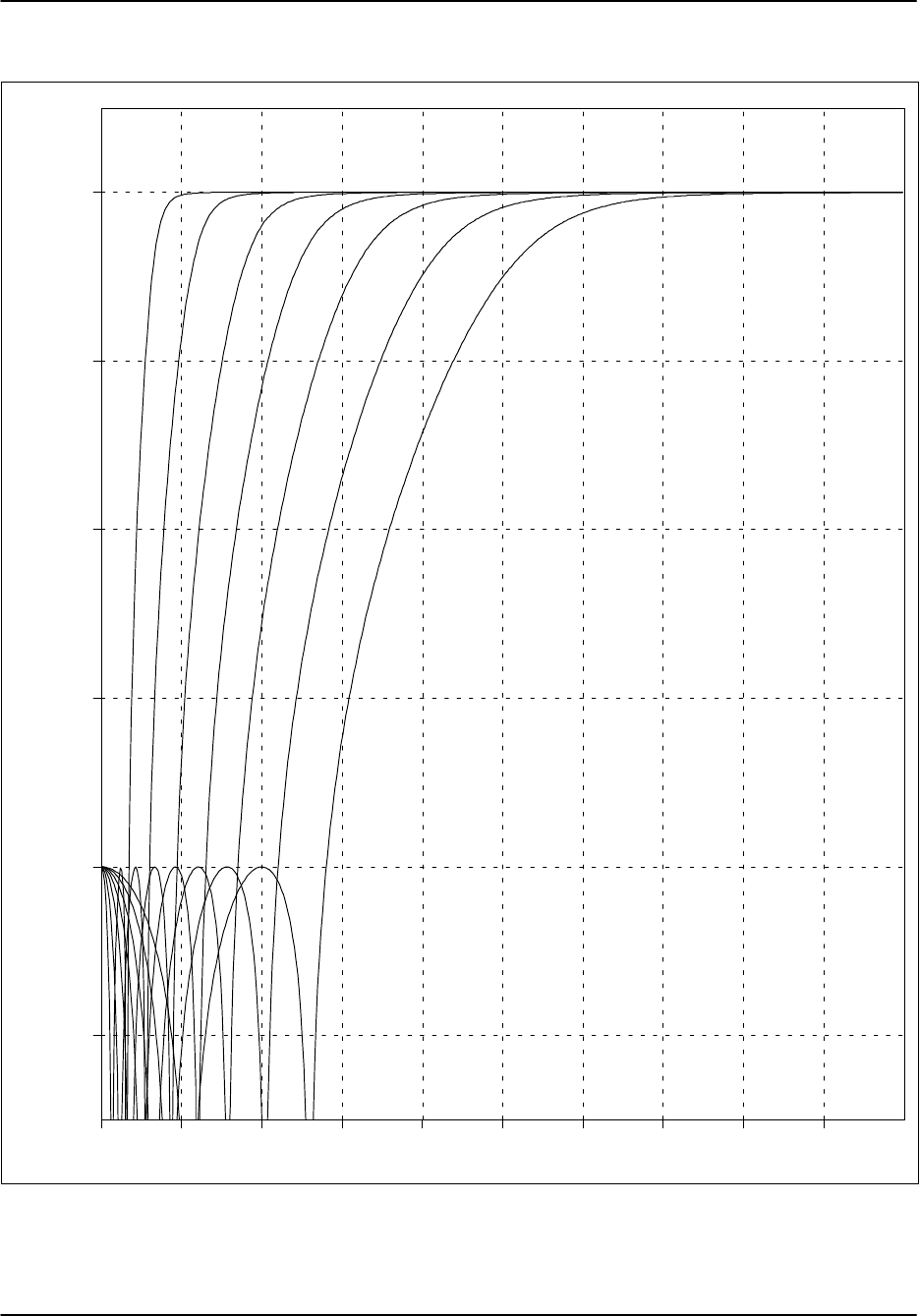
Clutter Filter Characteristics
RVP8 User’s Manual
April 2003
C–3
Figure C–1: 40 dB IIR Clutter Filter Responses
0.00 0.05 0.10 0.15 0.20 0.25 0.30 0.35 0.40 0.45
–50.0
–40.0
–30.0
–20.0
–10.0
0.0
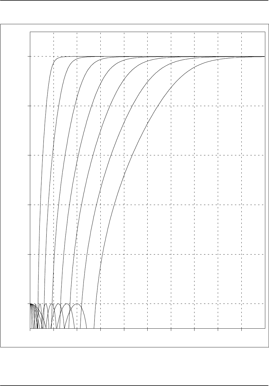
Clutter Filter Characteristics
RVP8 User’s Manual
April 2003
C–4
Figure C–2: 50 dB IIR Clutter Filters Responses
0.00 0.05 0.10 0.15 0.20 0.25 0.30 0.35 0.40 0.45
–50.0
–40.0
–30.0
–20.0
–10.0
0.0

References and Credits
RVP8 User’s Manual
April 2003
D–1
D. References and Credits
1. Tang Dazhang, et.al. (1984). Evaluation of an Alternating–PRF Method for Extending
the Range of Unambiguous Doppler Velocity. Preprints of the Conference on Radar
Meteorology, 22nd, 1984 pp.523–527.
2. Joe, Passarelli and Siggia (1995). Second Trip Unfolding by Phase Diversity
Techniques. Preprints of the Conference on Radar Meteorology, 27th, 1995 pp.
770–772.
3. Doviak, R. J., and Zrnic, D. S. (1993). “Doppler Radar and Weather Observerations.”
Academic Press, San Diego.
4. The JMA internal specification for Interference Filter algorithm for use on Chitose
airport Doppler weather radar is the basis for Alg.1 described in Section 5.1.4.
5. Environment Canada – Aldergrove BC, kindly supplied the snapshot of receiver data
that is plotted in Figure 4–6.

Installation and Test Procedure
RVP8 User’s Manual
April 2003
E–1
E. Installation and Test Procedure
(DRAFT)
Customer: _________________________________________
Serial No. Main: _________________________________________
AUX: _________________________________________
Delivery Date: _________________________________________
Radar Mfg./Type: _________________________________________
_________________________________________
Customer Engineer: _________________________________________
SIGMET Engineer: _________________________________________
Overview
This installation and test procedure is designed to assist SIGMET field engineers and customers
with the installation and testing of the RVP8 on a radar system. Because the tests also function as
an installation procedure, they must be completed in order. Failure to perform one step may
effect later tests.
A copy of the test results should be kept either on file or with the RVP8 User’s Manual. Do not
write in the manual since it will be replaced with an upgrade, instead make a copy and mark that.
For IRIS systems, it is recommended that the RVP8 TTY nonvolatile setups be put into a file on
your system in the ${IRIS_LISTINGS} directory. The file should be called something like
RVP8.26feb2000. The UNIX script command can be used to to create this file
Each test should be performed and signed off when it is completed. If a test does not pass, then
the problem should be remedied and the test repeated. If the test still does not pass, then an
additional sheet should be added to the test explaining the variance. A supplementary test sheet
is at the end of the test procedure.
After you have successfully completed the installation steps and tests in this procedure, your
RVP8 will be ready for connection to your application software such as SIGMET’s IRIS system.
There will be additional configuration and calibration to use the RVP8 with your application
software.
The following page is a convenient summary check list for the tests. Use this as a check list for
completing the installation and test procedure. We hope that you enjoy your new RVP8. Please
contact us if you have any problems or comments regarding this product or procedure at
support@sigmet.com.

Installation and Test Procedure
RVP8 User’s Manual
April 2003
E–2
Test Summary:
E.1 Installation Check
E.2 Power-up Check
E.3 Setup Terminal
E.4 Setup “V” Command (Internal Status)
E.5 Setup “M” Command (Board Configuration)
E.6 Setup “Mp” Command (Processing Options)
E.7 Setup “Mf” Command (Clutter Filters)
E.8 Setup “Mt” Command (General Trigger Setup)
E.9 Initial Setup of Information for Each Pulse Width
E.10 Setup “Mb” Command (Burst Pulse and AFC)
NO TAG Setup “M*” Command (Stand alone Settings)
E.11 Setup “M+” Command (Debug Options)
E.12 Setup “Mz” Command (Transmitter Phase Control)
E.13 Display Scope Check
E.14 Burst Pulse Alignment
E.15 Bandwidth Filter Adjustment
E.16 Digital AFC Voltage Alignment
E.17 Analog AFC Voltage Alignment
E.18 MFC Functional Test
E.19 AFC Functional Test
E.20 Input IF Signal Level Check
E.21 Dynamic Range Check
E.22 Receiver Bandwidth Check
E.23 Receiver Phase Noise Check
E.24 Hardcopy of Final Setups
All Tests Passed
For Customer _____________________________________ Date ____________
For SIGMET _____________________________________ Date ____________

Installation and Test Procedure
RVP8 User’s Manual
April 2003
E–3
E.1 Installation Check
Test Goal
Verify that the RVP8 is properly connected to the radar system and document some of the basic
radar characteristics. There are differences for TWT/Klystron vs magnetron radar systems.
Test Procedure
IF Digitizer (IFD) mounted in the radar receiver cabinet or other convenient location.
IF Digitizer Power Supply properly connect to AC Line voltage ___________VAC.
IFD IF input connection. IF Frequency ____________MHz.
RVP8 Chassis installed in (circle one) Rack Tabletop
Distance between IFD and RVP8 Chassis ____________
Fiber optic connection from IFD to RVP8 Chassis.
Uplink connection from IFD to RVP8 Chassis.
Trigger connections. List triggers in section E.8.
For magnetron systems only verify the following:
IFD burst pulse connected.
Is RVP8 AFC output used for STALO tuning (circle one) ? Yes No
AFC connected to IFD.
For Klystron or TWT systems only verify the following:
IFD COHO connected to Burst Input.
Is RVP8 Phase Shift Control used and connected to chassis (circle one) ? Yes No
If yes, then specify the phase shifts that correspond to the RVP8 Phase Control Output
Bits (attach a separate sheet).
Test Passed
For Customer _____________________________________ Date ____________
For SIGMET _____________________________________ Date ____________

Installation and Test Procedure
RVP8 User’s Manual
April 2003
E–4
E.2 Power-Up Check
Test Goal
Verify that the IFD and RVP8 properly power–up.
Reference:
RVP8 User’s Manual
, Tables 2–4 and section 2.3.5 .
Test Procedure
The RVP8 runs numerous power-up tests. The overall results of the tests are indicated by red and
green LED’s on the IFD and text on the RVP8 Display. In addition, the main board and auxiliary
board (optional) have red and green LED’s to signal test results.
Apply power to the RVP8 and the IFD. Verify the following:
For the IFD with RVP8 Main Chassis power on:
When power is applied to the IFD, the red and green lights blink and then go to on.
When the uplink is disconnected, the red light blinks and the green light is off.
When the fiber cable is disconnected, the red light is on and the green light is off.
For the RVP8 with the IFD power on
The front panel display shows the correct text.
Test Passed
For Customer _____________________________________ Date ____________
For SIGMET _____________________________________ Date ____________

Installation and Test Procedure
RVP8 User’s Manual
April 2003
E–5
E.3 Setup Terminal
Test Goal
Verify that the TTY Setups can be accessed and function properly.
Special Test Equipment
Either the IRIS dspx utility or a terminal or PC with terminal emulator (e.g., Procom or
minicom). This is to be supplied by the customer. SIGMET provides an adapter and cable to
convert the RJ11 connector on the RVP8 main board to a DN25–M connector. Note that a null
modem may be required.
Reference:
RVP8 User’s Manual
, Section 3.1
Option 1: Access to Terminal Setups via dspx chat mode at workstation.
This requires that the IRIS Utilities be installed and that the RVP8 is connected to the
workstation via a SCSI interface. Refer to the sample chat mode session in the dspx chapter of
the IRIS Utilities Manual. At your workstation, login as operator and type “dspx” in a terminal
window to enter the Doppler signal processor examiner utility. Now repeat the procedure in
section one of this test (i.e., press ESC, etc...).
Option 2: Access via a terminal or PC:
Connect the setup terminal. Configure the setup terminal for 9600 baud. Note, some terminals or
PC’s may require a null modem. Details of the TTY connection are provided in section 3.1.
Verify the following:
Test Procedure
Press the ESC key and verify that the RVP8 banner appears (see section 3.1.1).
Type “Help” or “?” and verify that the list of commands is displayed.
Issue the reset command “*” and verify that the front panel lights flash.
Type “q” or “quit” to exit the menus.
Record the type of hardware/software used for the connection:
___________________________________________________________
Null modem (circle one) required not required
Test Passed
For Customer _____________________________________ Date ____________
For SIGMET _____________________________________ Date ____________

Installation and Test Procedure
RVP8 User’s Manual
April 2003
E–6
E.4 Setup “V” Command (Internal Status)
Test Goal
Verify that the TTY setups for the Internal Status section are properly reported.
Special Test Equipment: Setup terminal.
Reference:
RVP8 User’s Manual
Section 3.1.4
Test Procedure
Enter the TTY setups and issue the “V” command to display the internal status. Note that we
will record the final values of all the settings at the end of the installation.
Status information is consistent with the board jumper settings.
Test Passed
For Customer _____________________________________ Date ____________
For SIGMET _____________________________________ Date ____________

Installation and Test Procedure
RVP8 User’s Manual
April 2003
E–7
E.5 Setup “Mc” Command (Board Configuration)
Test Goal
Verify that the TTY setups for the Board Configuration section are properly configured for the
customer application.
Special Test Equipment: Setup Terminal
Reference:
RVP8 User’s Manual,
Section 3.3.1
Test Procedure
Enter the TTY setups and type the “Mc” command. Set all the values as required.
Parameters set.
Test Passed
For Customer _____________________________________ Date ____________
For SIGMET _____________________________________ Date ____________

Installation and Test Procedure
RVP8 User’s Manual
April 2003
E–8
E.6 Setup “Mp” Command (Processing Options)
Test Goal
Verify that the TTY setups for the Processing Options section are properly configured for the
customer application.
Special Test Equipment: Setup Terminal
Reference:
RVP8 User’s Manual,
Section 3.3.2
Test Procedure
Enter the TTY setups and type the “Mp” command. Set all the values as required.
Parameters set.
Test Passed
For Customer _____________________________________ Date ____________
For SIGMET _____________________________________ Date ____________

Installation and Test Procedure
RVP8 User’s Manual
April 2003
E–9
E.7 Setup “Mf” Command (Clutter Filters)
Test Goal
Verify that the TTY setups for the Clutter Filters section are properly configured for the
customer application.
Special Test Equipment: Setup Terminal
Reference:
RVP8 User’s Manual,
Section 3.3.3
Test Procedure
Enter the TTY setups and type the “Mf” command. Set all the values as required.
Parameters set.
Test Passed
For Customer _____________________________________ Date ____________
For SIGMET _____________________________________ Date ____________

Installation and Test Procedure
RVP8 User’s Manual
April 2003
E–10
E.8 Setup “Mt” Command (General Trigger Setup)
Test Goal
Verify that the TTY setups for the General Trigger Setup section are properly configured for the
customer application.
Background
The RVP8 can output up to 6 different triggers. These can be delayed by different amounts, and
have different pulse widths. For example trigger 0 may go to fire the transmitter, while a
slightly delayed trigger 1 may be used for triggering an oscilloscope. The timing can be
different for each transmitter pulsewidth. The final timing adjustments will be done later in
Section E.14. Enter in the table below the purpose of each trigger, as well as the nominal start
time and pulse width. Note that start times are relative to range zero (middle of the burst pulse).
We recommend a nominal pulsewidth of 3 microseconds. This chart will be used in the next
section.
Magnetron radars using an analog COHO system often have a trigger generator circuit which
produces a trigger for the COHO latching and also for the transmitter pulse. This circuit should
be bypassed in an upgrade.
# Purpose Start Time Width
0 ________________________________ ________usec ________usec
1 ________________________________ ________usec ________usec
2 ________________________________ ________usec ________usec
3 ________________________________ ________usec ________usec
4 ________________________________ ________usec ________usec
5 ________________________________ ________usec ________usec
Special Test Equipment: Setup Terminal
Reference:
RVP8 User’s Manual,
Section 3.3.4
Test Procedure
Enter the TTY setups and type the “Mt” command. Set all the values as required. Note that the
PRF and pulse width set here are the current values, and values used at power-up.
Parameters set.
Test Passed
For Customer _____________________________________ Date ____________
For SIGMET _____________________________________ Date ____________

Installation and Test Procedure
RVP8 User’s Manual
April 2003
E–11
E.9 Initial Setup of Information for Each Pulse Width
Test Goal
Enter the initial values for the TTY Setups for each of the pulse widths. Note that the final
values of trigger timing, FIR filter impulse response length and bandwidth will be adjusted later.
Background
The duty cycle of the transmitter is the product of the PRF and the pulse width in seconds. For
example, a PRF of 1000 Hz and 1 microsecond pulse width is a duty cycle of 0.001. Thus a
transmitter with a 0.001 duty cycle limit could function at 1000 Hz and 1 microsecond pulse
width, or 500 Hz and 2 microsecond pulse widths.
The duty cycle limits of your radar should be obtained from your system documentation or radar
manufacturer. The RVP8 supports up to four pulse widths (coded 0 to 3), although most
transmitters typically support only two pulse widths. Record below the pulse width in
microseconds and the maximum PRF that is allowed for each pulse width.
# Pulse Width Max PRF
0 __________ microseconds ________ Hz
1 __________ microseconds ________ Hz
2 __________ microseconds ________ Hz
3 __________ microseconds ________ Hz
Special Test Equipment: Setup Terminal
Reference:
RVP8 User’s Manual,
Section 3.3.5
Test Procedure
Enter the TTY setups and type the “Mt #” command, once for each pulsewidth. Enter the start
time and widths for each trigger as documented on the previous page. For all unused triggers,
set the width to zero. Next enter the Maximum PRF from the table above. Set the initial
impulse response length to 1.5 times the pulsewidth, and the initial pass bandwidth to the inverse
of the pulsewidth.
Parameters set.
Test Passed
For Customer _____________________________________ Date ____________
For SIGMET _____________________________________ Date ____________

Installation and Test Procedure
RVP8 User’s Manual
April 2003
E–12
E.10 Setup “Mb” Command (Burst Pulse and AFC)
Test Goal
Verify that the TTY setups for the Burst Pulse and AFC Configuration section are properly
configured for the customer application.
Background: Magnetron vs Klystron Systems
Magnetron Systems: For magnetron systems, the phase and frequency of the burst pulse from
the transmitter is measured at IF. The phase measurement is used for digital phase locking and
2nd trip echo filtering and recovery. The frequency measurement is used to implement an analog
(+–10V) AFC output to control the STALO frequency. Note that an external AFC can be used
rather than the RVP8 AFC, but is not recommended.
Klystron or TWT–based Systems: The COHO is measured instead of the burst pulse. Note that
Klystron systems that use a phase shifter should input the phase shifted COHO into the IFD so
that the RVP8 can digitally lock to the actual transmitted phase. For Klystron systems the AFC
feedback loop is not used.
Special Test Equipment: Setup Terminal
Reference:
RVP8 User’s Manual,
Section 3.3.6
Test Procedure
Enter the TTY setups and type the “Mb” command. Set all the values as required.
Parameters set.
Test Passed
For Customer _____________________________________ Date ____________
For SIGMET _____________________________________ Date ____________

Installation and Test Procedure
RVP8 User’s Manual
April 2003
E–13
E.11 Setup “M+” Command (Debug Options)
Test Goal
Verify that the TTY setups for the Debug Options section are properly configured for the
customer application.
Special Test Equipment: Setup Terminal
Background
The RVP8 supports several test features that are configured in this section. For operational
systems, the simulation features should be turned off. SIGMET recommends that the LED’s be
set to “1:Go/Proc” so that the front panel red LED will flash during each processing cycle.
Reference:
RVP8 User’s Manual,
Section 3.3.7
Test Procedure
Enter the TTY setups and type the “M+” command. Set all the values as required.
Parameters set.
Test Passed
For Customer _____________________________________ Date ____________
For SIGMET _____________________________________ Date ____________

Installation and Test Procedure
RVP8 User’s Manual
April 2003
E–14
E.12 Setup “Mz” Command (Transmitter Phase Control)
Test Goal
Verify that the TTY setups for the Transmitter Phase Control section are properly configured for
the customer application. This feature is not used for magnetron systems since these have
inherent random phase that is measured, but not controlled.
Special Test Equipment: Setup Terminal
Reference:
RVP8 User’s Manual
, Section 3.3.8
Test Procedure
Enter the TTY setups and type the “M+” command. Set all the values as required.
Parameters set.
Test Passed
For Customer _____________________________________ Date ____________
For SIGMET _____________________________________ Date ____________

Installation and Test Procedure
RVP8 User’s Manual
April 2003
E–15
E.13 Display Scope Test
Test Goal
Verify that the display scope output functions properly.
Background
The RVP8 can use a standard oscilloscope as a display device for local configuration and testing.
This is a common item at radar sites and most technicians are familiar with its use. The
oscilloscope is provided by the customer or purchased as an option from SIGMET. When using
the dspx utility, the scope plot is drawn on the computer screen and an oscilloscope is not
required.
Reference:
RVP8 User’s Manual,
Section 4.1
Special Test Equipment:
Setup terminal
Analog oscilloscope (Optional)
Dspx Test Procedure
Enter the TTY setups and issue the “P+” command.
Verify that the test pattern is displayed OK.
Optional Scope Test Procedure
Connect the BNC cable from the Q output on the back of the RVP8 chassis to a vertical
input channel on the scope. Be sure to terminate the cable
Configure the scope per Section 4.1.
Enter the TTY setups and issue the “P+” command.
Adjust the scope time base, vertical gain, horizontal and vertical offsets so that the test
pattern appears as illustrated in Figure 4–1 of the Manual. If there is a problem doing
this, you can adjust the scope plots numbers using the “Mc”, see Section 3.3.1.
Verify that the test pattern is displayed OK.
Test Passed
For Customer _____________________________________ Date ____________
For SIGMET _____________________________________ Date ____________

Installation and Test Procedure
RVP8 User’s Manual
April 2003
E–16
E.14 Burst Pulse Alignment
Test Goal
Verify that the burst pulse is present and that its amplitude is sufficient. This test also aligns the
burst pulse in the burst pulse sample window.
Special Test Equipment: Setup terminal and display scope
Reference:
RVP8 User’s Manual,
Section 4.4
Test Procedure
Use the Mt command to select pulse width 0 and a safe PRF.
Set the transmitter on to radiate.
Issue the Pb command to obtain the burst pulse display. Use the L/R commands to find
the burst pulse. Use the l/r commands to fine tune the position of the burst pulse in the
burst pulse window.
Adjust the width of the burst pulse window using the I/i command to be slightly larger
than the burst pulse (e.g., ~50%).
Verify that the burst pulse power is in the range +1 to –12 dBm per the tabular display
on the setup terminal.
Record the burst pulse power
Pulsewidth #0: _____________ dBm
Pulsewidth #1: _____________ dBm
Pulsewidth #2: _____________ dBm
Pulsewidth #3: _____________ dBm
Repeat the above procedure for each pulse width.
In the event that the burst pulse is not found, try to detect the burst pulse on an oscilloscope
connected directly to the IF burst line (ahead of the IFD). On a magnetron radar, if the AFC is
not working it is possible the IF frequency is outside the IFD anti-aliasing filter bandwidth. It
may be necessary to go to manual frequency control to get this to work. If no burst pulse is
detected, then the radar should be serviced by an experienced technician. If the burst pulse is
power is too small or large, check the status of any attenuators or amps in the burst pulse signal
path. It might be necessary to adjust the gain buy installing a fixed attenuator or amplifier.
Test Passed
For Customer _____________________________________ Date ____________
For SIGMET _____________________________________ Date ____________

Installation and Test Procedure
RVP8 User’s Manual
April 2003
E–17
E.15 Bandwidth Filter Adjustment
Test Goal
Set the band width filter for each pulse width.
Reference:
RVP8 User’s Manual,
Section 4.5
Special Test Equipment: Setup Terminal and display scope
Test Procedure
Enter the Ps command mode and view the results on the display scope. Toggle the space
bar to show both the spectrum of the burst pulse and the spectrum of the bandwidth filter
response. Use the Z/z command to zoom the burst spectrum plot to approximately match
the height of the bandwidth filter response (which will have a smoother shape than the
burst pulse).
Use the Ww/Nn commands to adjust the width of the bandwidth filter plot to be slightly
narrower than the burst pulse. Then use the w/n commands to fine tune the filter width
such that the “DC–Gain:” is either “ZERO” or less than –64 dB.
Repeat for each pulse width that is used (use mt to change pulse width) and record:
FIR Length Bandwidth DC Gain
Pulsewidth 0 __________usec __________MHz _________ dB
Pulsewidth 1 __________usec __________MHz _________ dB
Pulsewidth 2 __________usec __________MHz _________ dB
Pulsewidth 3 __________usec __________MHz _________ dB
Test Passed
For Customer _____________________________________ Date ____________
For SIGMET _____________________________________ Date ____________

Installation and Test Procedure
RVP8 User’s Manual
April 2003
E–18
E.16 Digital AFC Voltage Alignment (Optional)
Test Goal
Verify that the RVP8 AFC output controls the STALO over the correct span.
Special Test Equipment: Setup TTY and display scope
Background
The RVP8 implements an AFC based on the measurement of the burst pulse frequency. The
control output is available in 8 bits on the phase control signals of the RVP8 J13 connector, or on
the RxNet7 J16, or in 16+ bits on the DAFC. A frequency control span of approximately +– 7
MHz is expected. If your STALO requires more control lines, jumper the higher lines.
Check the specification of the STALO and document the following. To calculate the digital span
take the desired frequency minus the base frequency divided by the frequency step.
STALO base frequency after jumpering high bits: _______ MHz
STALO frequency step _______ MHz
Desired frequency span: _______ to _______ MHz
Desired digital span: _______ to _______
Test Procedure
Verify that JP23 and JP24 are set to AB to enable all 8 bits of digital AFC.
Use the setup terminal to set the Digital AFC span as required in the Mb section.
Use the setup terminal and display scope in the Pb (plot burst) mode to verify that the
burst pulse is properly centered. Any pulsewidth can be used.
Set to MFC using the “=” command, and adjust the control to the lowest setting using the
“D” command. Record the results below.
Raise the control using “U” to within 0.1 MHz of the IF frequency. Record the results.
Raise the control using “U” to the highest setting. Record the results.
Verify that sufficient span is covered, and the the power at the end points is sufficiently
high to run the AFC loop.
voltage frequency
Midpoint: _________A/D _________ MHz.
Lower limit: _________A/D _________ MHz.
Upper limit: _________A/D _________ MHz.
Test Passed
For Customer _____________________________________ Date ____________
For SIGMET _____________________________________ Date ____________

Installation and Test Procedure
RVP8 User’s Manual
April 2003
E–19
E.17 Analog AFC Voltage Alignment (Optional)
Test Goal
Verify that the RVP8 AFC output voltage is properly adjusted to match the STALO input control
voltage.
Special Test Equipment
Calibrated Oscilloscope or Voltmeter.
Setup TTY and display scope
Background
The RVP8 implements an AFC based on the measurement of the burst pulse frequency. The
control output is an SMA labeled “AFC” on the IFD module which connects to the STALO
control voltage input. The output signal is an analog voltage in the range +–10V. A frequency
control span of approximately +– 7 MHz (for a 30 MHz IF) is expected. Some STALOs contain
a nominal frequency adjustment. The alignment procedure is different in that case.
Check the specification of the STALO and verify the following:
STALO analog control input range _______V to _______V
STALO frequency control range +/– __________ MHz
Test Procedure, initial setup
Connect a scope or digital Voltmeter to the AFC line, either at the IFD or the STALO.
Use the setup terminal and display scope in the Pb (plot burst) mode to verify that the
burst pulse is properly centered. Any pulsewidth can be used.
Set the test switches on the IFD to output the Midpoint Voltage
SW1–A SW2–B
Test Procedure, STALO without adjustment
Adjust the “Offset” pot by screwdriver on the IFD module until the the IF frequency dis-
play on the setup terminal is approximately the desired IF frequency (e.g., 30 MHz). Re-
cord the results below.
Set the test switches on the IFD to output the AFC low test voltage.
SW1–A SW2–A
The voltage on the monitoring scope or Voltmeter will decrease. The burst pulse frequen-
cy may either increase or decrease depending on the nature of the voltage control in the
STALO.
Adjust the “Gain” pot by screwdriver on the IFD module until the frequency stops chang-
ing or until the burst pulse frequency is 7 MHz off the center frequency (e.g. for 30 MHz
IF, either 23 or 37 MHz) whichever occurs at a higher voltage. Record the results.
Set the test switches on the IFD to output the AFC high test voltage.
SW1–A SW2–C

Installation and Test Procedure
RVP8 User’s Manual
April 2003
E–20
Reduce the gain slightly (CCW turn) and verify that the frequency changes such that it
becomes closer to the center IF frequency. If it does not change, then continue to reduce
the gain until it does. If the frequency is more than 7 MHz from the IF center frequency,
then reduce the gain until the frequency is 7 MHz off. Record the results below.
Test Procedure, STALO with adjustment
Adjust the “Offset” pot by screwdriver on the IFD module until the voltage is at the
middle of the desired voltage span.
Adjust the “Offset” pot on the STALO until the the IF frequency display on the setup ter-
minal (Pb mode) is approximately the desired IF frequency (e.g., 30 MHz). Record the
results below.
Set the test switches on the IFD to output the AFC low test voltage.
SW1–A SW2–A
The voltage on the monitoring scope or Voltmeter will decrease. The burst pulse frequen-
cy may either increase or decrease depending on the nature of the voltage control in the
STALO.
Adjust the “Gain” pot by screwdriver on the IFD module until low end of the desired
voltage span is reached, or until the burst pulse frequency is 7 MHz off the center fre-
quency (e.g. for 30 MHz IF, either 23 or 37 MHz) whichever occurs at a higher voltage.
Record the results below.
Set the test switches on the IFD to output the AFC high test voltage.
SW1–A SW2–C
Reduce the gain slightly (CCW turn) and verify that the frequency changes such that it
becomes closer to the center IF frequency. If it does not change, then continue to reduce
the gain until it does. If the frequency is more than 7 MHz from the IF center frequency,
then reduce the gain until the frequency is 7 MHz off. Record below.
Test Procedure, final cleanup
Set the switches back to the run position (SW1–B and SW2–B), and disconnect the T for
the Voltmeter or scope monitor. This cable can introduce a lot of noise into the system.
voltage frequency
Midpoint: _________Volts _________ MHz.
Lower limit: _________Volts _________ MHz.
Upper limit: _________Volts _________ MHz.
Test Passed
For Customer _____________________________________ Date ____________
For SIGMET _____________________________________ Date ____________

Installation and Test Procedure
RVP8 User’s Manual
April 2003
E–21
E.18 MFC Functional Test and Tuning (Optional)
Test Goal
Verify that the Manual Frequency Control (MFC) is functioning properly. Skip this test if you
are not using the RVP8’s AFC.
Reference:
RVP8 User’s Manual,
Section 4.5
Special Test Equipment: Setup Terminal and display scope
Test Procedure
Enter the Ps command (Plot burst spectrum and AFC).
Use the “=” command to enter the MFC (manual frequency control) mode. Verify that
the MFC mode is indicated by the “Manual” notation next to the AFC % output indicator
on the terminal.
Use the U/u and D/d commands and verify that these commands shift the measured IF
frequency (as displayed on the TTY) either up or down. The U command should increase
the frequency and the D command should decrease the frequency. If the sense is re-
versed, then go to the Mb command menu and change the question “Burst frequency in-
creases with increasing AFC voltage”.
Using the U/u and D/d commands, verify the limits of the AFC tuning and fill in the
table below:
AFC % Measured Freq (MHz)
–100% ____________
0% ____________
+100% ____________
The 0% AFC value should be within approximately +–0.2 MHz of the center IF frequen-
cy (e.g., 30 MHz) . The values at +– 100% should correspond to approximately +– 7
MHz of the center IF frequency, or at the maximum span that is supported by the STA-
LO, whichever is less.
Toggle the MFC mode to AFC by typing the “=” symbol and and verify that the terminal
indicator changes from “Manual” to “AFC”. Then exit the Ps menu.
Test Passed
For Customer _____________________________________ Date ____________
For SIGMET _____________________________________ Date ____________

Installation and Test Procedure
RVP8 User’s Manual
April 2003
E–22
E.19 AFC Functional Test (Optional)
Test Goal
Verify that the AFC properly tracks the burst pulse frequency.
Reference:
RVP8 User’s Manual,
Section 4.5
Special Test Equipment: Setup Terminal and display scope
Test Procedure
Use the setup terminal to enter the Ps mode and observe the output on a display scope. Verify the
following:
Verify that the system is in AFC mode by checking that the text on the terminal for the
AFC % output says “AFC”.
Verify that the frequency displayed on the setup terminal is within +– 15KHz of the cen-
ter IF frequency (the default value for the AFC hysteresis outer limit in the Mb com-
mand). For example in the range 29.985 to 30.015 MHz. If it is not in this range then
verify that it moves within this range.
Turn radiate off for 10 minutes and then turn the radiate back on. Observe that the AFC
properly tracks the magnetron frequency as the magnetron warms.
Similarly, set the control signal to the maximum and minimum values using MFC, then
turn on AFC. Observe that the AFC properly tracks back to the correct frequency.
Perform the tests above for each pulse width and verify that the AFC properly tracks the
center frequency.
For pulsewidth 0.
For pulsewidth 1
For pulsewidth 2.
For pulsewidth 3.
Test Passed
For Customer _____________________________________ Date ____________
For SIGMET _____________________________________ Date ____________

Installation and Test Procedure
RVP8 User’s Manual
April 2003
E–23
E.20 Input IF Signal Level Check
Test Goal
Verify that the input signal level is optimized for the IFD. This is done be observing the power in
the noise using the Pr command.
Reference:
RVP8 User’s Manual,
Section 4.6
Special Test Equipment: Setup Terminal and display scope
Test Procedure
Set the transmitter to radiate and elevate the antenna to >45 degrees to minimize the ef-
fects of weather or clutter echoes (including earth noise). Be sure the antenna azimuth is
pointed away from the sun or any known RF interference sources you may have.
Note: This entire procedure may also be performed with the transmitter off
since, in theory, it is only measuring properties of the receiver. However, you
may notice some noise interaction between the Tx and Rx.
Use the setup terminal to enter the Pr command and the display scope to view results.
Use the Ll/Rr commands to move out in range to a start range of 50 km so that only
noise is present.
Record the powers displayed on the setup terminal. You can use the V/v command to
increase/decrease averaging of samples to make the noise measurement more stable.
Total: _________ dBm, Filtered: _________ dBm
Now remove the cable connecting the IF signal into the IFD. Again record the powers:
Total: _________ dBm, Filtered: _________ dBm
Add attenuation and/or amplification by an amount such that the Filtered noise power is
approximately 7 dB higher when the signal is connected (See Section 2.2.8).
After verifying the above rise in noise level, disconnect the output cable from the LNA
and verify that the noise drops to the same level as when the IFD IF-Input was discon-
nected. This verifies that the dominant noise is indeed coming from the LNA, and not
from any of the subsequent IF amplifiers.
Test Passed
For Customer _____________________________________ Date ____________
For SIGMET _____________________________________ Date ____________

Installation and Test Procedure
RVP8 User’s Manual
April 2003
E–24
E.21 Dynamic Range Check
Test Goal
Verify the receiver dynamic range is in excess of 80 dB.
Important: This test requires the injection of an RF test signal over a 90 dB range.
Damage to the LNA could occur. Check the LNA specification to verify the
maximum signal that it can accept. The output from the signal generator
(accounting for cable and coupler losses) should not be allowed to exceed this
value.
Reference:
RVP8 User’s Manual
section 4.6
Special Test Equipment:
Setup Terminal and display scope
RF signal generator
Test Procedure
Run the radar and test signal generator for 20 minutes to allow proper warm-up of the
system prior to the test. This will allow the AFC to stabilize.
After warm-up is complete, turn the radiate off but leave the receiver on since the test
signal generator may be damaged by the transmitter. The antenna should be elevated to
20 degrees and the azimuth should be set to point away from any known microwave
sources including the sun.
Use the setup terminal to enter the Mt command to set the pulse width to 0.
Use the Mt 0 command to temporarily configure the FIR impulse response to 2.89 usec
(I/i command) and 0.59 MHz bandwidth (N/n and W/w commands). These settings are
for the purpose of benchmarking the receiver performance. Do not save this result since
it would override your previously configured band width and impulse response.
Connect the test signal generator to inject a signal at RF ahead of the LNA.
Enter the Pr mode and make the following settings:
Use the space bar to toggle to the power spectrum plot.
Use the L/l and R/r commands to set the start to 50 usec.
Use the T/t command to set the plot span to 50 usec
Use the V/v command to set averaging to 10 samples
Set the signal generator to a value that is approximately 20 dB above noise and observe
the scope plot. Adjust the frequency of the test signal generator to make the frequency of
the spectrum at the correct IF frequency.
Turn off the signal generator RF output and record the “Filtered” noise power
Siggen power: none RVP8 Filtered power:_________dBm

Installation and Test Procedure
RVP8 User’s Manual
April 2003
E–25
Turn on the signal generator RF with about 20 dB of signal above noise. Now reduce the
power until you the Filtered power is approximately 1 dB above the noise level measured
in the previous step. Verify this by toggling the signal generator RF ON and OFF. The
samples will be a little noisy, but getting the signal exactly 1 dB above noise is not re-
quired. Record the signal generator setting for the 1 dB above noise power (minimum
detectable power).
Siggen power (Pmin):__________dBm RVP8 Filtered power:_________dBm
Increase the signal generator output power by 10 dB steps until saturation of the Filtered
power is observed.
Important: Do not increase the signal generator power such Total Power exceeds
the Safe Total Power Limit for Pr command display +10 dBm or damage to the
RVP8 A/D convertor could result.
Back off the siggen power to approximately 10 dB below saturation. Now use 1 dB steps
to more carefully define the saturation point to within +– 1 dB (e.g., for a 0.2 dB roll–
off). Record the signal generator setting.
Siggen power (Psat):____________dBm RVP8 Filtered power:_________dBm
The Receiver dynamic range is:
______________ dB = Psat – Pmin
Verify that the receiver dynamic range is greater than or equal to 80 dB.
Check that the signal generator frequency has not drifted by looking at the plot. If it is
off by more than 0.1 MHz, retune and repeat the test.
Exit Pr and do a “restore” to restore the saved settings.
Test Passed
For Customer _____________________________________ Date ____________
For SIGMET _____________________________________ Date ____________

Installation and Test Procedure
RVP8 User’s Manual
April 2003
E–26
E.22 Receiver Bandwidth Check
Test Goal
Verify the receiver bandwidth is in excess of 14 MHz.
Background
For proper functioning of the high speed A/D convertors, it is necessary that approximately 14
MHz of broadband noise is available at the IFD. This noise does not interfere with the signal to
noise ratio because the bandwidth filter is applied afterwards. The bandwidth of the anti-aliasing
filter should be the limiting factor. This test uses the same hookup as the previous test (Section
E.21). For dual polarization systems, you expect to get a narrower bandwidth.
Reference:
RVP8 User’s Manual,
section 4.6
Special Test Equipment:
Setup Terminal and display scope
RF signal generator
Test Procedure
Connect the test signal generator to inject a signal at RF ahead of the LNA.
Enter the Pr mode and make the following settings:
Use the space bar to toggle to the power spectrum plot.
Use the L/l and R/r commands to set the start to 50 usec.
Use the T/t command to set the plot span to 50 usec
Use the V/v command to set averaging to 1 sample
Set the signal generator power to a value that is approximately 60 dB above noise and
observe the scope plot. Adjust the frequency of the test signal generator in 1 MHz steps
to cover the whole range of the scope plot. Mark the total power measured on the plot on
the next page.
Set the signal generator power to a value that is approximately 60 dB above noise and
observe the scope plot. Adjust the frequency of the test signal generator in 1 MHz steps
to cover the whole range of the scope plot. Mark the total power measured on the plot
below.
Verify that the 3dB point gives approximately 14 MHz of bandwidth.
Test Passed
For Customer _____________________________________ Date ____________
For SIGMET _____________________________________ Date ____________

Installation and Test Procedure
RVP8 User’s Manual
April 2003
E–27
Graph of Total Power vs. IF frequency
–70
–60
–50
–40
–30
–20
–10
0
10
14 16 18 20 22 24 26 28 30 32 34 36 38 40

Installation and Test Procedure
RVP8 User’s Manual
April 2003
E–28
E.23 Receiver Phase Noise Check
Test Goal
Verify the stability of the STALO by looking at the phase noise of a clutter target.
Background
For proper velocity calculations and for ground clutter rejection, it is required that the radar’s
STALO maintain a stable frequency, and that the transmitted pulse contain no amplitude or
phase artifacts.
Special Test Equipment:
IRIS ascope utility, or similar program
Known clutter targets with no weather signal
Test Procedure
Configure the radar for normal operation expect pointing at a known clutter target.
Run the IRIS ascope program, and configure as follows: 16-bit time series, Spectrum not
from DSP, spectrum size 256, Rectangular window, short pulse width, high PRF, no clut-
ter filters. Select the maximum range and number of bins to get the maximum resolution
over the target. For targets < 24 km, use 201 bins, 25 km. Select the range bin of the
target. Record the Az, El, range and phse noise below.
Try minor changes in Az, El, and Range to get the lowest phase noise. The goal is less
than 1 degree within 20 km.
Az: _____ El:_____ Range:_____ Phase Noise:_____
Az: _____ El:_____ Range:_____ Phase Noise:_____
Az: _____ El:_____ Range:_____ Phase Noise:_____
Az: _____ El:_____ Range:_____ Phase Noise:_____
Az: _____ El:_____ Range:_____ Phase Noise:_____
Az: _____ El:_____ Range:_____ Phase Noise:_____
Test Passed
For Customer _____________________________________ Date ____________
For SIGMET _____________________________________ Date ____________

Installation and Test Procedure
RVP8 User’s Manual
April 2003
E–29
E.24 Hardcopy of Final Setups
Test Goal
Make a hardcopy of all the final setups, and attach to the tests.
Special Test Equipment: Setup Terminal
Dspx Chat Mode Test Procedure
Start script logging with commands “cd /usr/sigmet/config/listings”, “script
RVP8.26feb01”.
Enter the TTY setups and type the “??” command to list all the TTY setups.
Exit dspx, and exit script logging with “exit”.
Print the file.
Terminal Test Procedure
Either use a known screen capture method on your terminal or PC, or make a copy of chapter 3
of the manual, attach to this test, and mark the results in it.
Test Passed
For Customer _____________________________________ Date ____________
For SIGMET _____________________________________ Date ____________

Installation and Test Procedure
RVP8 User’s Manual
April 2003
E–30
E.25 IFD Stand-alone SigGen Bench Test
Test Goal
Verify that the IFD analog I/O is working properly in an isolated environment.
Background
These stand-alone production tests are are performed on every IFD prior to shipment.
Special Test Equipment:
IRIS dspx utility, IF Signal Generator, Voltmeter
Test Procedure
Begin by running dspx and temporarily reverting to factory settings with ’f’.
Enter the “Mb” menu and choose an IF frequency fIF MHz that matches the center fre-
quency of the IFD’s anti-alias bandpass filter.
Enter the “Pr” menu, and type “RRRTTVVVVV” to move the starting plot range to
30km, the plot interval to 20µsec, and the averaging factor to 10. Also type two space
characters to switch to the spectral display plot.
Attach an IF SigGen to the input of the anti-alias filter that feeds the “IF-In” IFD input.
Set the SigGen for fIF MHz at 0dBm. Verify that the filtered power is within 0.5dB of
–1dBm, and that a single clean spectral line is plotted. Use the “Z” or “z” keys to zoom
Up/Down as needed.
Increase the SigGen power in 1dB steps until distortion harmonics are seen on the plot.
This should occur at 6–7dBm.
Reduce the SigGen power to –20dBm, and sweep the frequency in 1MHz steps over a
20MHz band centered on fIF. Verify that the bandwidth of the anti-alias filter matches its
designed value (14MHz BW for the 30, 57.5 and 60MHz filters, and 4MHz BW for the
16MHz filter).
Switch the SigGen off, and verify that the noise floor filtered power is between –83dBm
and –81.0dBm. Note: a very good quality shielded test cable is required here.
Move the SigGen cable to the other IFD filter input, and swap the plots by flipping IFD
SW2 to its “A” position. Repeat the above four tests, now on the “Burst-In” SMA port.
Place IFD SW1 in its “A” position, and verify that the AFC output voltage varies in a
negative-zero-positive pattern as SW1 is flipped from A-B-C. Use the offset pot to set a
nominal 0-Volt output, and the gain pot to set a 5V span.

Index
RVP8 User’s Manual
May 2003
Index–1
Index
A
A/D input, B–23
Acquisition clock, TTY setup, 3–10
AFC
algorithms, 5–5
analog, 2–14
digital, from DAFC, 2–27
introduction, 1–31
TTY setup, 3–27
Angle
input, 2–20
output, 2–20
S/D input, 2–21
Angle synchronization, introduction, 1–27
Angle syncing, LSYNC command, 6–36
Autocorrelations
algorithms, 5–12
introduction, 1–26
Automatic Frequency Control. See AFC
Azimuth angle, B–16 , B–17 , B–26
B
Back panel, B–8
Backup
copy
CDROM, A–23
floppy, A–23
ftp, A–22
introduction, A–17
rda_backup, A–20
rda_restore, A–21
BIOS settings, A–6
Burst pulse, introduction, 1–22
C
Calibration, introduction, 1–11
CCOR threshold
algorithms, 5–17
qualifier, 5–19
CDROM
mounting, A–28
un–mounting, A–22
CFGINTF command, 6–43
Chassis
connector panel, 2–20
direct connections, 2–19
installation, 2–18
Clutter correction. See CCOR
Clutter filter
algorithms, 5–11
characteristics, C–1
comparison of FFT and pulse pair, 5–64
LFILT command, 6–21
microsuppression
algorithms, 5–13
TTY setup, 3–13
TTY setup, 3–16
Coax uplink
installation, 2–17
specification, 2–32
COHO, introduction, 1–14
Configuration examples
dual polarization, 1–7
Klystron, 1–6
magnetron, 1–5
Connector panel, B–12
Corrected reflectivity, introduction, 1–30
Correction for Tx Power, algorithms, 5–9
D
DAFC
CTI STALO example, 2–29
description, 2–27
drawings, pin out, B–31
jumpers, 2–28
MITEQ STALO example, 2–31
Debug Options, TTY setup, 3–33
DFT/FFT, introduction, 1–29
Diagnostics
introduction, 1–32
TTY setup, 3–4
Differential phase. See PhiDP
Differential reflectivity. See ZDR
Digital receiver, introduction, 1–17

Index
RVP8 User’s Manual
May 2003
Index–2
Dual polarization
algorithms, 5–36
calibration, 5–61
dual channel receiver, 5–40
introduction, 1–7 , 1–30
KDP calculation, 5–49
modes, 5–42
notation, 5–42
radar systems, 5–38
signal generator tests, 5–76
simultaneous receive example, 5–40
standard moments, 5–50
thresholding, 5–60
Dual polarization , modes
alternating dual channel, 5–48
alternating single channel, 5–47
fixed transmit, 5–45
simultaneous transmit, 5–46
Dual PRF. See Velocity unfolding
Dual PRT. See Velocity unfolding
E
Elevation angle, B–19 , B–20 , B–26
ENDRAY_ output, introduction, 1–28
Environment, 1–43
F
Features
digital transmitter, 1–1
open hardware and software, 1–2
frequency agility, 1–14
I/Q LAN output, 1–3
LAN connection, 1–3
pulse compression, 1–14
SoftPlane, 1–2
FFT, introduction, 1–29
FFT mode
algorithms, 5–64
TTY setup, 3–13
Fiber optic downlink, installation, 2–17
FIFO, output, 6–1
FIR filter
algorithms, 5–4
TTY setup, 3–23
Floppy disk
formatting, A–18
mounting, A–19
un–mounting, A–22
Fourier transform. See FFT
G
Get processor parameters, GPARM com-
mand, 6–22
GPARM, command, 6–22
H
History, 1–1
Host computer interface
complete command list, 6–1
socket, 2–24
I
I/O–62
connector panel
drawings, B–12
pin out, B–12
connector panel, 2–20
introduction, 1–15
I/Q, introduction, 1–3 , 1–30
IFbandwidth, 2–9
frequency selection
installation, 2–13
TTY setup, 3–25
IF to I/Q processing , 1–23
saturation, 2–8
signal processing, 1–21 , 5–4
IFD
adjustment, 2–6
drawings, B–28
dynamic range, 2–9
I/O connections, 2–5
input power, 1–43 , 2–1 , 2–4
installation, 2–2
introduction, 1–9
LED indicators, 2–6

Index
RVP8 User’s Manual
May 2003
Index–3
mounting, 2–4
reference clock, 2–15
revision history, 2–3
sampling clock, 1–21
signal level, 2–11
IIR filter. See Clutter filter
Initiate processing, PROC command, 6–13
Install utility, A–28
Installation
software. See Software
test procedure, E–1
Interference Filter
algorithms, 5–7
CFGINTF command, 6–43
Intermediate frequency. See IF
IOTEST command, 6–10
K
KDP
algorithm. See Dual Polarization
description, 5–36
Klystron
example, 1–20
introduction, 1–6
L
Large–signal linearization, algorithms, 5–9
LDR
algorithm. See Dual polarization
description, 5–37
LDRNV command, 6–40
LEDs
on IFD, 2–6
SLED command, 6–38
LFILT command, 6–21
LOG filter, threshold qualifier, 5–19
LOG threshold, algorithms, 5–18
Login
logout, A–4
operator, A–3
poweroff, A–4
procedure, A–3
root, A–3
LRMSK command, 6–2
LSIMUL command, 6–31
LSYNC command, 6–36
M
Magnetron
example, 1–18
introduction, 1–5
Main chassis
back panel, B–8
drawings, B–2
general description, B–2
input power, 1–43 , 2–1 , 2–18 , B–7 , B–9
PC I/O, B–10
PCI cards, B–11
Mean velocity. See Velocity
Motherboard, introduction, 1–13
N
Network
management
adding services, A–34
basics, A–31
default configuration, A–31
DNS, A–33
hostname, A–32
IP address change, A–32
NTP time synch, A–33
socket interface, 2–24
telnet, A–34
Noise sample, SNOISE command, 6–11
NOP command, 6–2
O
Optional argument list, XARGS command,
6–42
OTEST command, 6–11
P
Passwords, A–2
Phase control
output, 2–20
TTY setup, 3–34

Index
RVP8 User’s Manual
May 2003
Index–4
PhiDP
algorithm. See Dual Polarization
description, 5–36
Power off, A–4
Power requirements, B–7 , B–9
Power requirements, 2–1 , 2–18
Power requirements, 1–43
PPP mode, TTY setup, 3–13
PRF
limits, PWINFO command, 6–34
SETPWF command, 6–36
TTY setup, 3–18 , 3–23
PROC command, 6–13
Pulse compression, introduction, 1–14
Pulse pair, introduction, 1–29
Pulse–pair processing. See PPP
Pulsewidth control
introduction, 1–31
PWINFO command, 6–34
SETPWF command, 6–36
TTY setup, 3–18
PWINFO command, 6–34
R
R2 processing, TTY setup, 3–13
Random phase
algorithms, 5–70
introduction, 1–30
TTY setup, 3–18
Range averaging
algorithms, 5–13
introduction, 1–27
LRMSK command, 6–3
Range mask, load command (LRMSK), 6–2
Range normalization, LDRNV command,
6–40
Range resolution, TTY setup, 3–23
Range unfolding, introduction, 1–30
RBACK command, 6–41
rda_backup, A–20
rda_restore, A–21
Reflectivity
algorithms, 5–13
introduction, 1–30
Reflectivity calibration, 5–25
Relays, B–21
Reliability, 1–43
Reset, TTY setup, 3–3
RESET command, 6–33
Reset time, TTY setup, 3–5
Restore, introduction, A–17
RhoHV, description, 5–37
ROM revision, TTY setup, 3–3
Round trip delay, TTY setup, 3–5
RVP8/Rx card, introduction, 1–10
RVP8/Tx card, introduction, 1–13
S
S/D input, B–26
Saturation headroom, TTY setup, 3–14
SBC, introduction, 1–13
Scope holdoff ratio, TTY setup, 3–12
SETPWF command, 6–36
SIG threshold, algorithms, 5–18
Simulations
burst pulse, TTY setup, 3–32
LSIMUL command, 6–31
output data, TTY setup, 3–34
SLED command, 6–38
SNOISE command, 6–11
Socket interface, 2–24
Softplane, sofplane.conf, A–11
Software
configuration
introduction, A–10
softplane.conf, A–11
utilities, A–10
installation, A–6
automatic startup, A–7
BIOS, A–6
FPGA ”flash”, A–8
from RDA CDROM, A–7
introduction, A–5
reboot test, A–9
introduction, A–1
login, A–2
upgrade, A–24
download files, A–25
install utility, A–28

Index
RVP8 User’s Manual
May 2003
Index–5
version, A–24
SOPRM command, 6–4
Speckle filter
algorithms, 5–21
introduction, 1–28
Spectrum width
algorithms, 5–15
introduction, 1–30
SQI threshold
algorithms, 5–16
qualifier, 5–19
STAR, 5–46
su, A–3
Support, software upgrade, A–24
Synchro input, B–26
T
TAG lines
introduction, 1–27
TTY setup, 3–15
Test point, output , 2–21
Testing
test procedure, E–1
with signal generator, 5–75
Thresholding
algorithms, 5–19
adjusting, 5–20
introduction, 1–28
Time series, algorithms, 5–11
Trigger
blanking, 1–31
external input, TTY setup, 3–18
input, 2–22
installation, 2–22
introduction, 1–31
output, 2–22
outputs, TRIGWF command, 6–33
TTY setup, 3–18
waveform, example of Dual PRF, 5–35
TRIGWF command, 6–33
TTY setup
complete listing, 3–1
M+ – debug options, 3–33
Mb – burst pulse and AFC, 3–25
Mc – board configuration, 3–10
Mf – clutter filters, 3–16
Mp – processing options, 3–13
Mt – general trigger setups, 3–18
Mz – transmitter phase control, 3–34
P+ – plot test pattern, 4–3
Pb – plot burst pulse timing, 4–6
Pr – plot receiver waveforms, 4–23
Ps – plot burst spectra and AFC, 4–11
TTYOP command, 6–38
V – view internal status, 3–3
TTYOP command, 6–38
TWT, example, 1–20
U
Uncorrected reflectivity, introduction, 1–30
Unfolding, introduction. See Velocity unfold-
ing
V
Velocity
algorithms, 5–15
introduction, 1–30
Velocity unfolding
algorithms, 5–30 , 5–32
introduction, 1–28
W
Weather signal processing, introduction, 1–25
WSP threshold, qualifier, 5–19
X
XARGS command, 6–42
Z
ZDR
algorithm. See Dual polarization
description, 5–36