Baron Services XDD-1000C C-BAND DOPPLER WEATHER RADAR User Manual TR1038
Baron Services Inc C-BAND DOPPLER WEATHER RADAR TR1038
Contents
- 1. Modulator Manual
- 2. Users Manual Part 1
- 3. Users Manual Part 2
- 4. Users Manual Part 3
- 5. S10 OPERATION AND MAINTENANCE MANUAL
- 6. S10 FAST TRAC MILLENIUM USERS GUIDE
- 7. S10 TECHNICAL MANUAL
- 8. S10 RECEIVER AND PROCESSOR USERS MANUAL PART 1
- 9. S10 RECEIVER AND PROCESSOR USERS MANUAL PART 2
- 10. S10 RECEIVER AND PROCESSOR USERS MANUAL PART 3
S10 TECHNICAL MANUAL
Technical Manual
C-Band 1 MW Transmitter
Pulse Systems Part Number TR-1038
Magnetron SFD 313V
August 22, 2003
Prepared By:
Pulse Systems Inc.
222 Bolivar Street
Canton, MA 02021
Prepared For
Barron Services
4930 Research Drive
Huntsville, AL 35805
S10

1
TABLE OF CONTENTS
GENERAL DESCRIPTION..................................................................... 2
Introduction.................................................................................. 2
System Specifications .................................................................... 2
General Technical Discussion .......................................................... 2
Mechanical................................................................................... 4
POWER SUPPLY SECTION .................................................................. 6
Technical Approach ....................................................................... 6
Schematic Diagram ........................................................................ 6
Mechanical Considerations.............................................................. 8
Interface ...................................................................................... 8
MODULATOR SECTION....................................................................... 9
Technical Approach ....................................................................... 9
Schematic diagram ........................................................................ 9
Mechanical Considerations............................................................ 10
Interface .................................................................................... 11
MAGNETRON HEATER POWER SUPPLY .............................................. 12
Technical Discussion ................................................................... 12
OPERATING INSTRUCTIONS.............................................................. 13
Procedure For Setting All System Parameters ................................... 13
MAINTENANCE................................................................................ 15
Introduction................................................................................ 15
The Power Supply Section............................................................. 15
The Modulator Section.................................................................. 15
APPENDIX ...................................................................................... 16
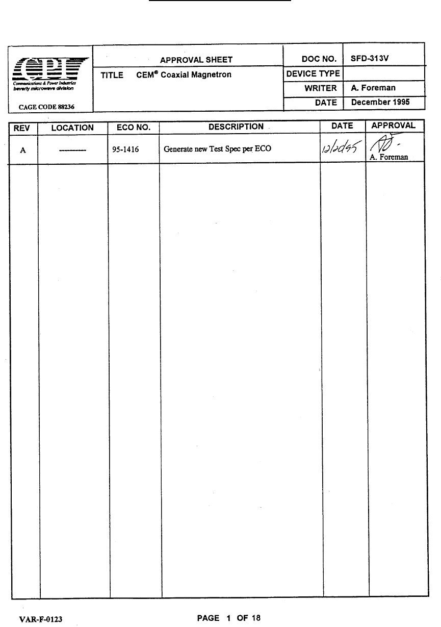
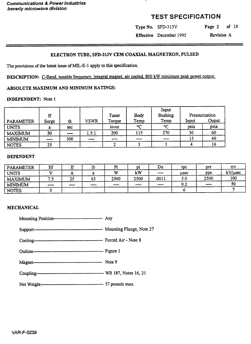
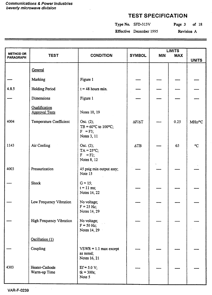
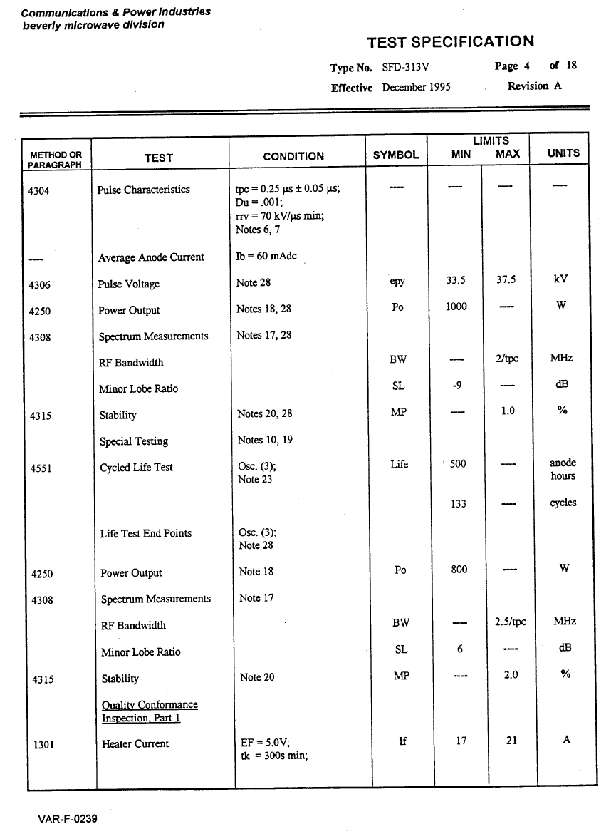
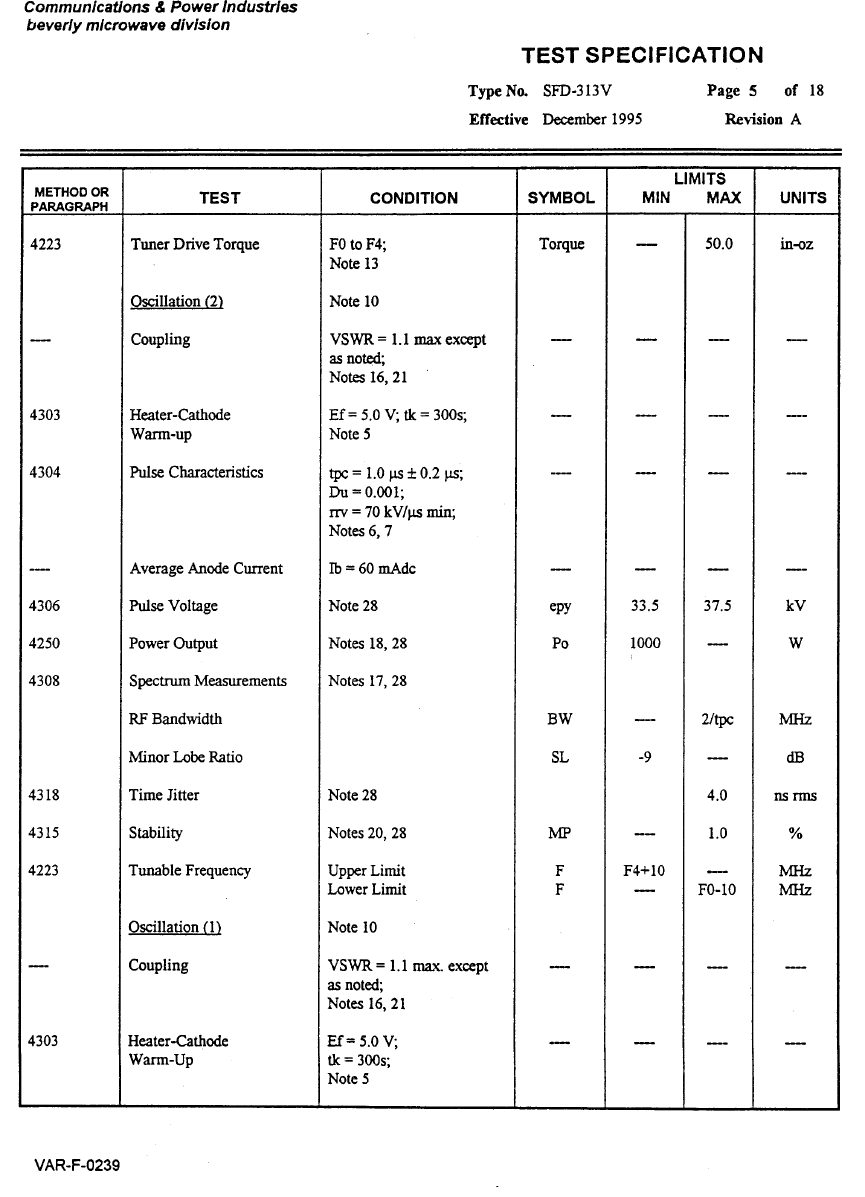
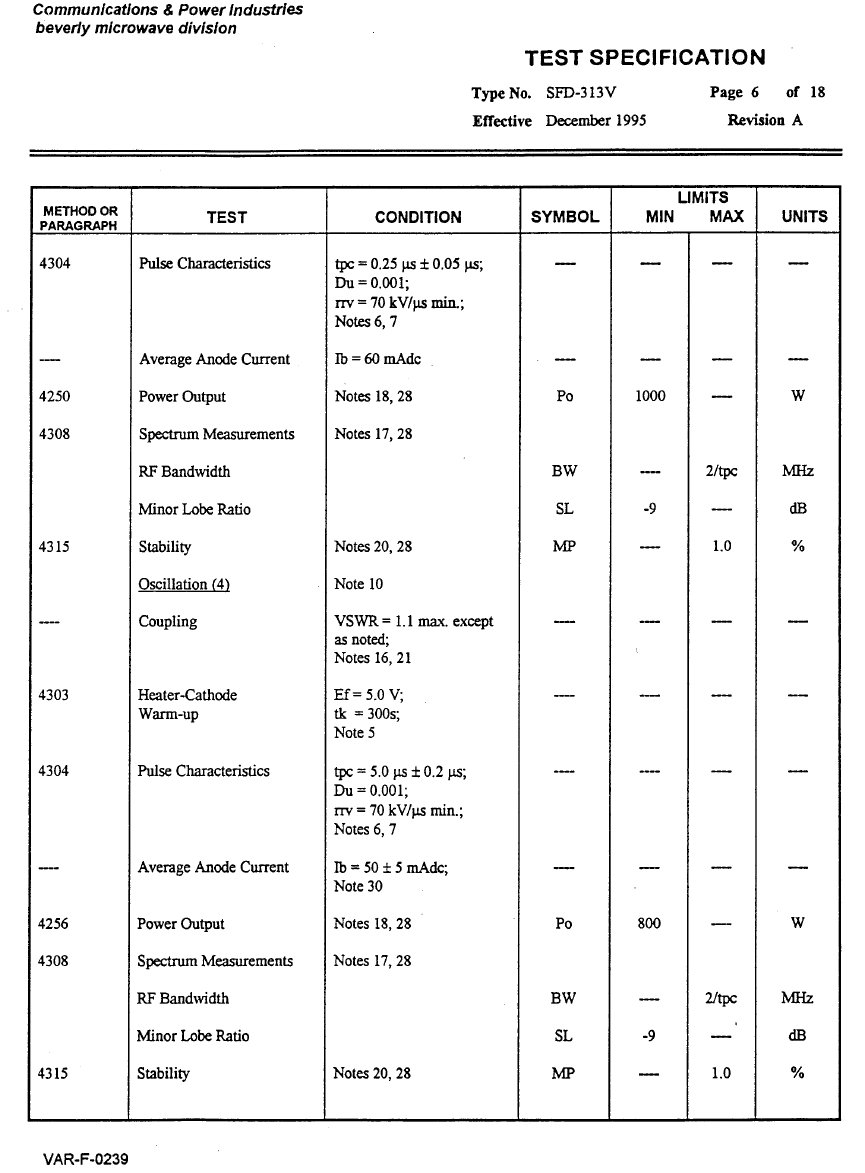
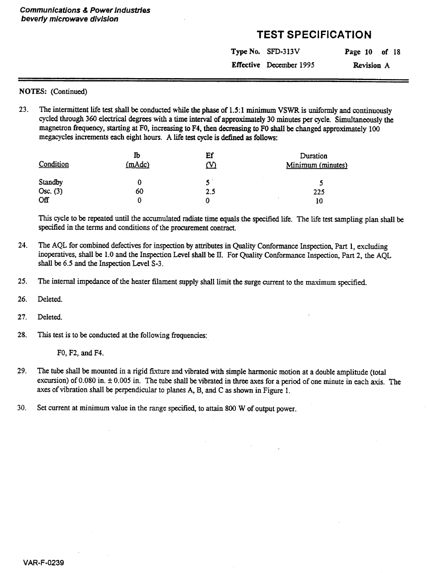
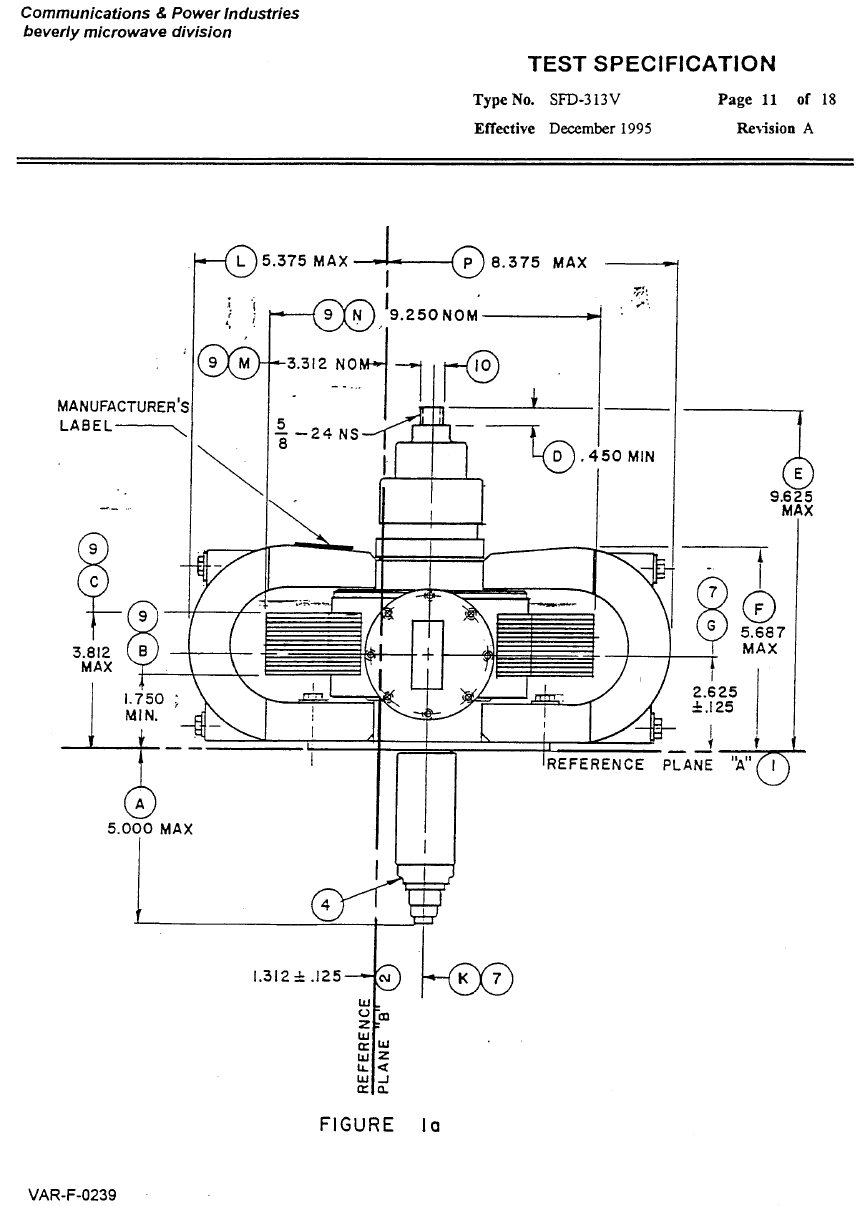
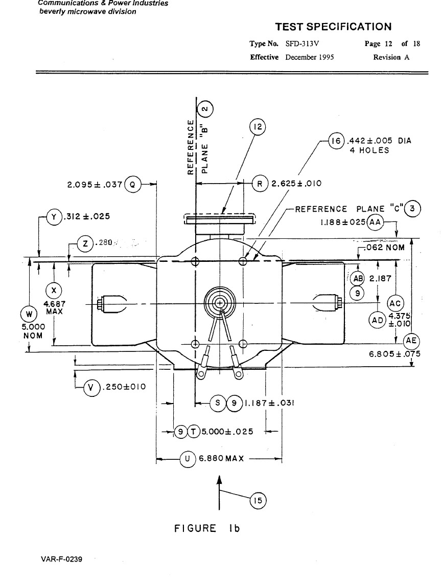
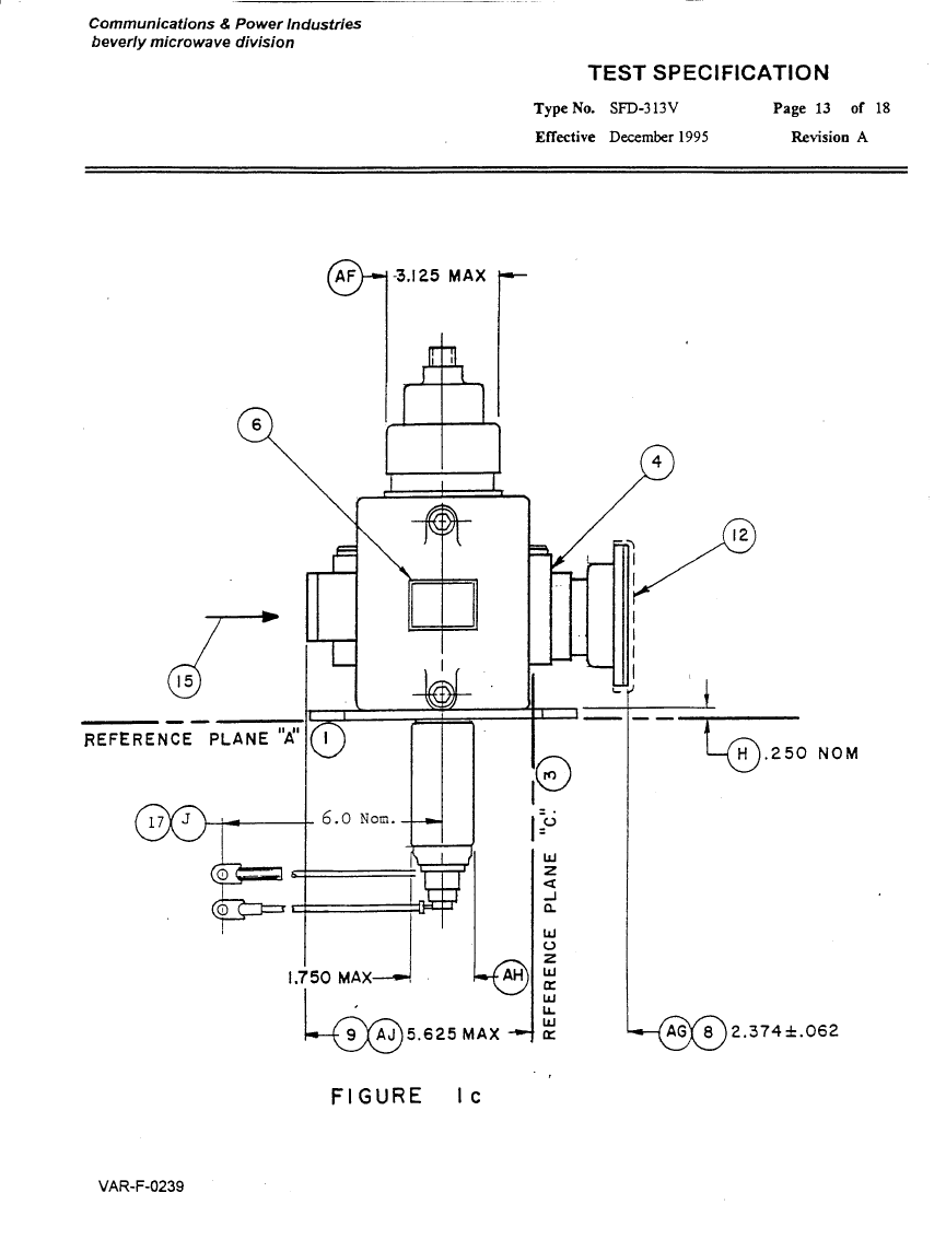
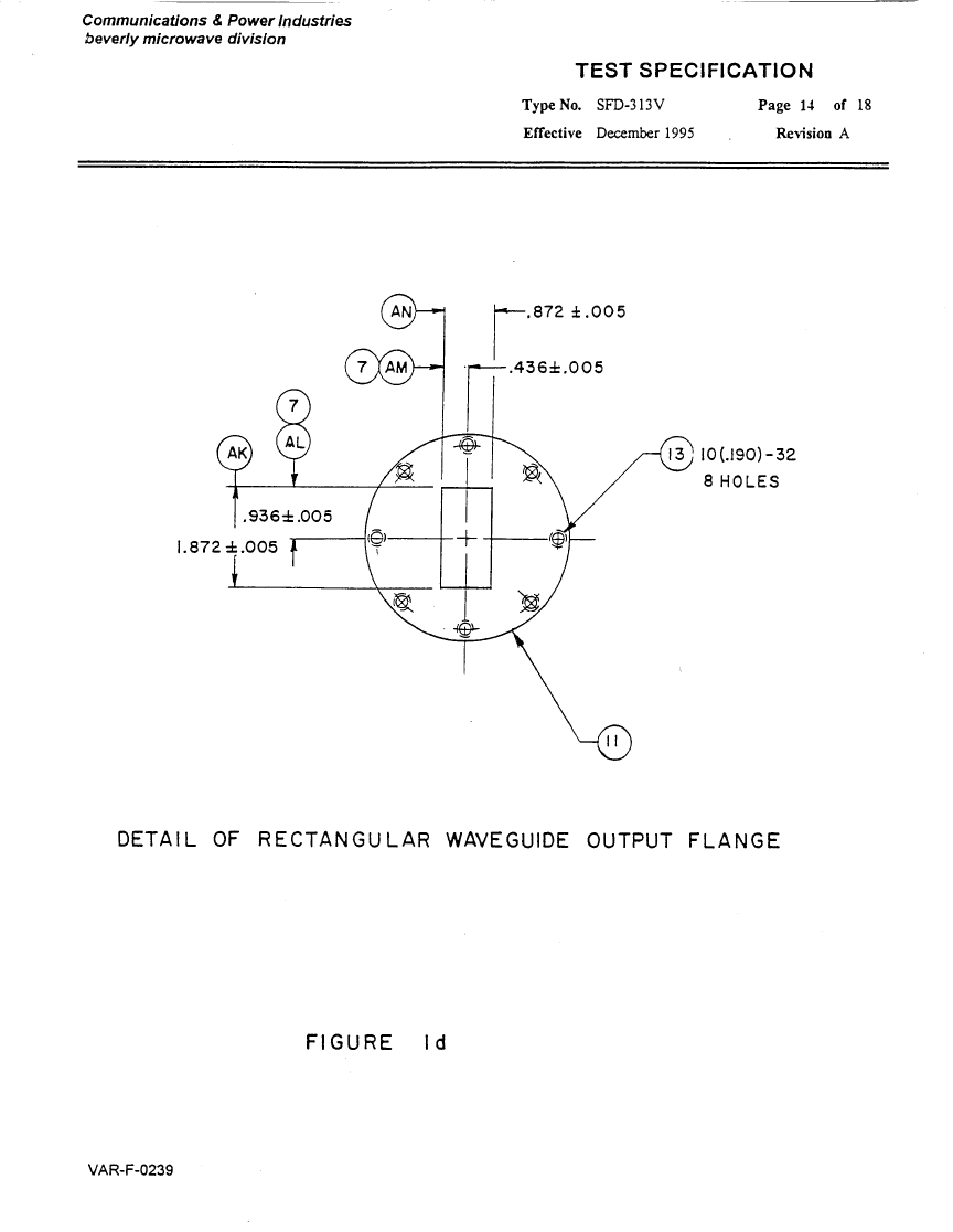
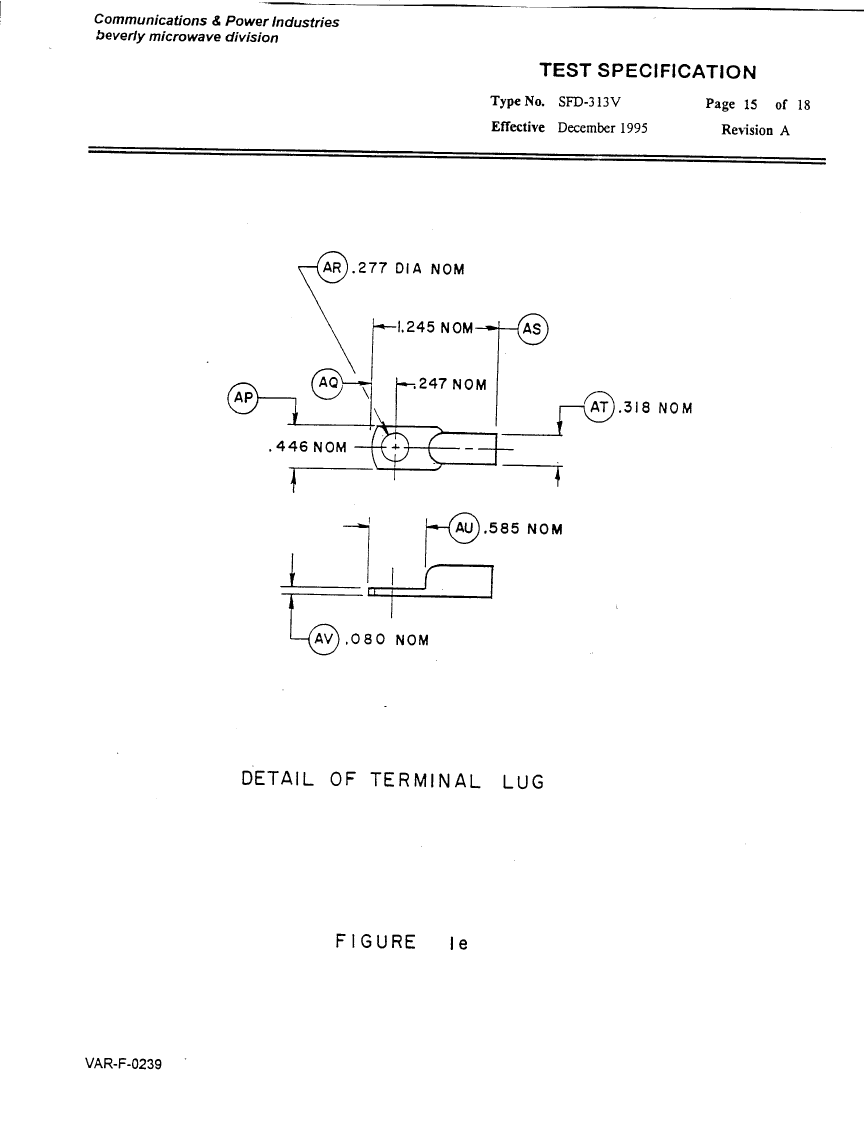
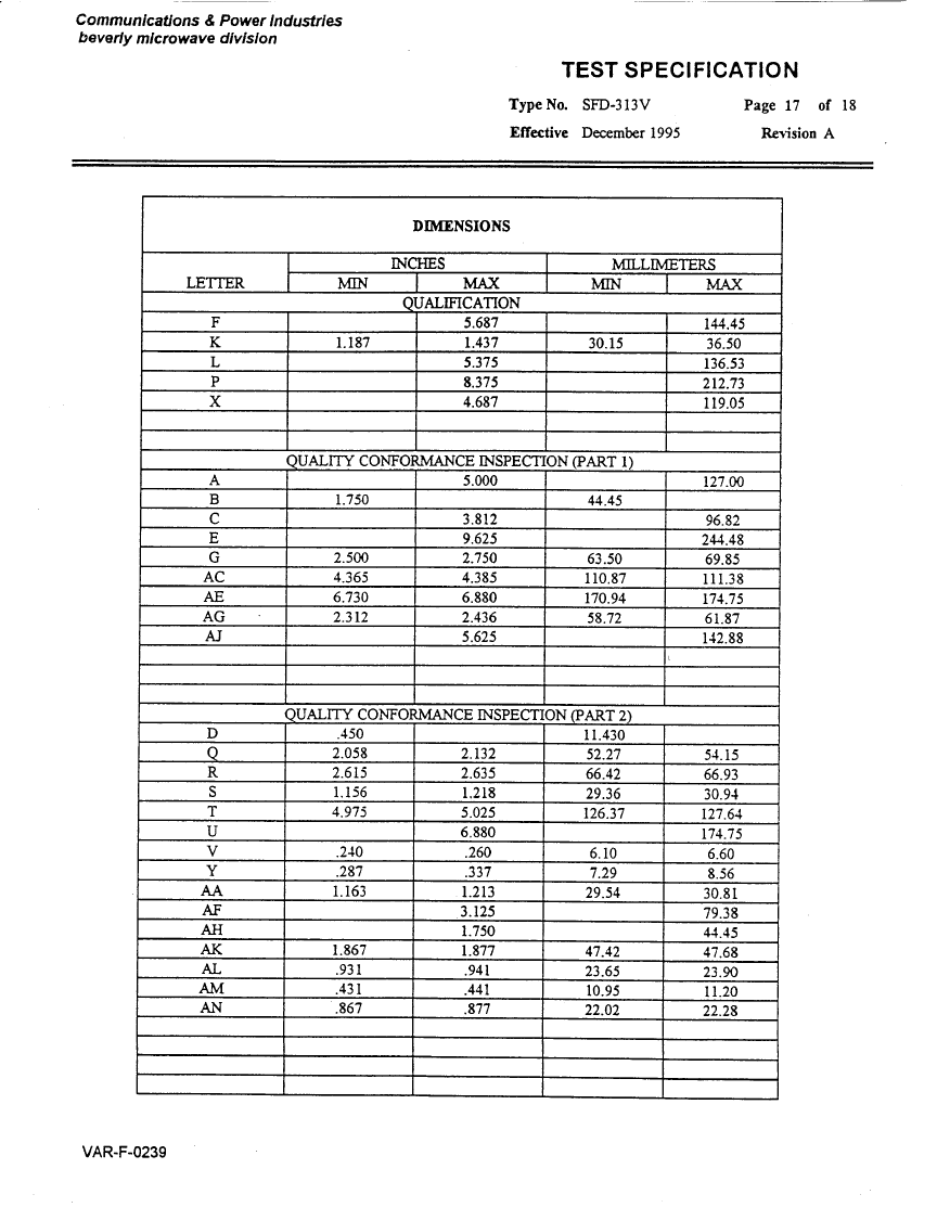
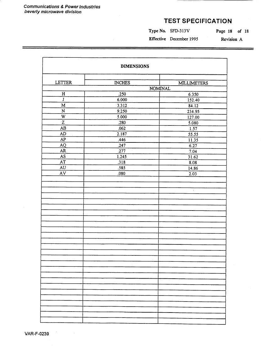
Magnetron Specifications.............................................................. 17
Figures...................................................................................... 35

2
GENERAL DESCRIPTION
Introduction
The system described in this manual consists of four main parts:
A: The Main High Voltage Power Supply
B. The Modulator System
C. The Corner Cutter
D. Filament Power Supply
In order to achieve the design objectives of this contract, our design approach has to
follow state-of-the-art technology in solid-state design. The evolution of third
generation IGBT technology and the various power supply topologies makes it a
challenge to make the right choice for our present application.
The design objective calls for generating narrow pulses of various pulse-widths
under single pulsing conditions. The cathode pulses will drive a CPI Magnetron
operating in the C-Band frequency with minimum peak output power 1.0 Mw.
The power supply section is self-contained in an enclosure as shown in Figure 1.0.
Our design is based on series resonance topology driving a full bridge circuit.
The modulator is a hard-tube type, utilizing IGBT technology, and is under oil
environment. The mechanical enclosure for the modulator is shown on Figure 2.0
System Specifications
The specifications for the systems are outlined in the Appendix along with the
magnetron specifications.
General Technical Discussion
As previously mentioned, the whole system consists of the high-voltage power
supply and the solid-state hard tube modulator.
The solid-state power supply contains the following sections:
A. Off-Line Rectifiers, Filters, and Controls
B. Series Resonance Full Bridge Inverter
C. Series Resonance Frequency Modulation Control
D. High Voltage Output Section
E. Low Voltage Power Supplies
3
F. Hard Tube Modulator Control
G. Solid-State Filament Power Supply
The Modulator section contains the following sections:
A. Switch Driver Assy
B. PRF Driver
C. High Power Switch Section
D. Magnetron Peak Current Detector
The input voltage for the system is 220 VAC single phase and it enters the system
via a connector located in the rear lower panel of the cabinet.
The input line voltage enters the system via a circuit breaker located on the control
panel. The control panel is located on the front upper section of the main cabinet.
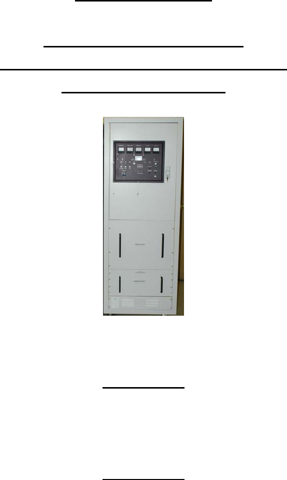
Figure 3.0 shows the mechanical configuration of the system. The front view of
cabinet shows the control panel located on the upper section.
The main electrical system diagram is shown on figure 4.0. The main power is
switched on by the circuit breaker on the control panel and is further fused before
entering the power supply section. It enters the front end of the power supply and is
applied to the power factor correction section.
The Power Factor Correction Module performs the rectification, in-rush current
limiting and preregulation of the input line voltage.
The power factor module provides a preregulated DC Voltage level of 360 VDC. The
above 360 VDC is applied to the input of the series resonance converter which, in
turn, provides a final adjustable level of 0-900 VDC available at the modulator
section.
The above DC output is sent to the modulator section through three of wires leaving
the back of the power supply section. The input PRF, which is TTL level, enters the
control panel and is further processed by the Modulator control circuit.
It enters the Modulator Control Circuit, which transforms this input signal to a
selectable pulse-width level proper for triggering the modulator section of the system.
The modulator control circuit performs additional functions, as will be discussed later
under the Power Supply section.
Figure 5.0 shows the complete power supply section of the system. The power
supply also provides the low voltage bias levels required by the modulator. The
modulator section receives the trigger input from the modulator control circuit located

4
in the power supply.
The function of the modulator is to receive the input signal and provide a high-power
pulse of 36-38 KV at the cathode of the magnetron, thus causing the magnetron to
oscillate at C-Band frequency under the selected pulse width set by the modulator
control circuit.
The maximum cathode peak current under the above conditions is 60 Amperes
peak. The above voltage and current levels result in a peak output power of 1.0
MW. In the meantime, the filament power supply requires programming according to
the magnetron specifications. For the stand-by condition, the filament voltage is set
to 5.0 VDC at 18-22 Amps and is reduced to 2.0 VDC at the maximum duty cycle of
.001.
The cathode voltage is fed to the magnetron via the high voltage bushing located on
top of the modulator.
The magnetron peak current is being monitored via a wide band current transformer
under the magnetron and over the modulator section. The sensitivity of the current
transformer is set to 0.1v/ amp.
For example, if we are looking at the scope displaying the current monitor output, a
6.0 volt peak pulse level will indicate 60 Amps peak magnetron current. Next to the
modulator high voltage output terminal is a spark gap, which prevents the magnetron
from reaching much higher than normal pulse voltage levels. The voltage of the
spark gap is set to 45 KVPK.
When the magnetron misfires the pulse output voltage could theoretically reach a
maximum pulse voltage level of 76 KV. The spark gap limits this level to a maximum
of 45 KV pulse thus reducing the voltage stress level of the system to a more
reasonable level.
Mechanical
As previously mentioned, the mechanical outline drawings of both the power supply
and modulator are shown in Figures 1.0 and 2.0.
Figure 3.0 shows the mechanical outline of the whole system
The power supply is of dry construction and is mounted on rails at the lower section
of the equipment cabinet.
It can be removed by first removing the rear connections at the rear section of the
unit and then slide the whole assembly out of the cabinet.
5
The modulator on the other hand is contained in an oil-filled container for insulating
and cooling reasons. The modulator is mounted above the power supply on its own
compartment.
Next to the modulator, the corner cutter assembly is mounted and its output is
connected to the cathode terminal of the modulator.
The magnetron is mounted above the modulator shelf and the high voltage bushing
projects into the modulator compartment through a hole located on the magnetron
shelf. Under this hole, the wide band current transformer is mounted and its output
is terminated to a BNC connector located on the control panel.
The magnetron compartment provides the space for the assembly of all the
microwave components required by the system.

6
POWER SUPPLY SECTION
Technical Approach
In order to meet our design objectives of reliability, efficiency, simplicity and cost,
our approach for the system is derived from our past experience.
For the power supply, we feel that the series resonance converter topology is the
best choice.
First the efficiency of the system is greatly optimized under this topology and both
the RFI and EMI levels are kept at a minimum. In contrast with PWM systems, the
series resonance converter operates smoothly with sine wave currents, rather than
square wave excitation. Efficiency levels of 95% are easily attained under the
chosen power supply topology with proper design techniques.
For the modulator section of the system, the approach is a hard tube modulator
topology using solid-state technology switching.
Schematic Diagram
Figure 5.0 shows the complete schematic of the power supply.
The main sections of the power supply are as follows:
A: Input relay section
B: Power factor section
C: Full bridge inverter section
D: High voltage output section
E: SRI control circuit
F: Heater PWM & Metering circuit
G: Magnetron heater section
The input power enters the power supply at the command of the 24-VDC-control
voltage. Relay K2 receives the +24vdc level and allows the main power to enter the
power supply. The control transformer T-1 when energized provides four regulated
output voltage levels:
A; +24 VDC
B: +28 VDC
C: +15 VDC
7
D: -12 VDC
The above voltage levels are regulated via linear series regulator circuits with
associated filter networks.
The input line voltage enters next the Power Factor Correction Circuit. The power
factor modules (three) rectify the input line voltage, regulate it, and limit the input
inrush current to a reasonable level.
The final level of 360 VDC is applied to a capacitive input filter properly sized for the
full power of the system and, finally, is applied to the full bridge circuit shown next to
the power factor circuit. The full bridge circuit is driven by the SRI Control circuit,
which generates, regulates and provides protection for the whole power supply
system.
The SRI control circuit sends two drive pulses, noted as Drive A and Drive B. Both
pulses are identical in amplitude and pulse-width but they are frequency modulated,
depending on the power demand of the system. This is the way the power supply
regulates.
When the load demands more power, the frequency of the drive pulses is raised to a
higher level and when the load demand diminishes, the frequency slows down to the
point that the system meets its regulating requirements.
The two drive pulses are applied to the bridge circuit of the main inverter and they
drive the main switches into full conduction during their on state and off during their
off state. Turn-on and turn-off occur at zero current switching conditions.
This alternating voltage waveform is impressed across the primary winding of the
inverter transformer, with the proper turns ratio, the output is rectified and filtered to a
maximum level of 900 VDC.
The output voltage of the power supply is controlled by a potentiometer located at
the front control panel. The top arm of the potentiometer is connected to +10 VDC
and the wiper is connected to one terminal of an operational amplifier. The other
input terminal of the operational amplifier is connected to the feedback terminal of
the output section of the power supply.
The design objective is to keep the two input terminals of the operational amplifier to
an equal level. If the arm of the potentiometer is set to a higher voltage level, thus
demanding higher output voltage from the power supply, the feedback signal is
raised to the same corresponding level as the arm of the potentiometer. This is the
way the system regulates against input and load variations.

8
Metering circuits are provided for the output voltage of the power supply, the output
current, the filament voltage, the magnetron average current and the system voltage.
The return section of the power supply goes through a sensing resistor whose level
is detected and processed for over-current protection.
Mechanical Considerations
Figure 1.0 shows the mechanical configuration of the power supply. The enclosure
is made of chemically treated aluminum alloy and is cooled with fans located inside
the power supply frame.
The power level of the power supply system is set to a maximum of 5.0. KW. The
maximum temperature rise of the power supply is 25 degrees Centigrade over the
ambient temperature.
The system operating at maximum duty cycle of .001 requires a power level of
36,000 x 60 x .001 = 2,160 watts. If we assume a system efficiency including both
the power supply and modulator of 75%, the power level of the power supply
becomes 2,880 watts, which is lower than the maximum power supply limit of 5000
watts.
Interface
The power supply is controlled by the front panel controls of the main cabinet of the
system. The local control in the front panel of the power supply adjusts the output
level of the power supply and performs also the resetting action against various
system faults. The radiate command and pulse width selection is done also via the
front panel controls.
All controls and monitors are located in the front control panel.
The power supply communicates with the modulator and monitors fault conditions
relating to the magnetron misfiring, over-current and over-duty conditions.
Figure 4.0 is a functional diagram showing the power supply and modulator
interconnected with the control panel.

9
MODULATOR SECTION
Technical Approach
Several solid-state modulator systems have been designed, built, and delivered by
Pulse Systems. All designs feature the Mosfet or IGBT technology.
Our design approach for reliable operation has been to limit the switching voltage
level within the solid-state switch capability and to avoid stacking switches in series
configuration. The design approach is shown in Figure 6.0
Schematic diagram
For the discussion, which follows, we make reference to Figure 6.0
The whole system is enclosed in oil environment for insulating and cooling reasons.
Figure 6.0 shows the main sections that are contained in the modulator system.
The PRF driver is set at the front section of the system. It receives its signal from the
modulator control, designed to be slaved to an external PRF generator.
The only control that the external generator has over the modulator control is the
frequency count. The rest of the pulse width processing and control is governed by
the modulator control circuit.
The complete modulator system consists off three drive circuits, a supervisory
control circuit governing the operating conditions of the drive circuits and the output
section.
The output section consists of a solid state switch assembly, three high voltage step-
up pulse transformers, and a pulse shaping network.
In order to generate the narrow pulses with proper rise and fall time, the pulse
transformer design demands special consideration in selecting the proper magnetic
material and proper winding configuration. This information is proprietary to Pulse
Systems Inc.
The magnetron tube also requires proper rate of rise of the cathode voltage. This
level has to be kept between 90 and 110 kV/µsec in order to avoid magnetron
moding. In order to achieve this low rate of rise of voltage, a corner cutter is added
to the system to prepare the tube before conduction.

10
The schematic diagram of the corner cutter is shown in figure 6 next to the modulator
circuit diagram.
The solid state switch assembly is turned on during the positive portion of the drive
pulse and kept off when the drive pulse goes to a negative bias level.
The output pulse-width of the system bears a close relationship to the drive pulse of
the switch driver.
The pulse current is monitored via a wide-band current transformer and fed back to
the peak over current detector, which removes the drive pulse from the switch driver
circuit if the magnetron pulse current is out of specification.
The modulator control circuit has a provision and allows a number of peak over-
current conditions within the time frame of one minute. This number is selectable via
a switch assembly located in the modulator control circuit. Missing magnetron
pulses and magnetron misfiring occurs quite often and the above-mentioned quality
of the modulator control circuit is essential to allow the system to run and overcome
the magnetron temporary miss occurrences.
If the abnormalities associated with magnetron continue on beyond the set limits, the
system latches to the stand-by condition and a manual reset is required.
The magnetron average current level is also detected in the same way and
controlled.
Figure 6 shows also the schematic of the corner cutter. Diodes D1-D40 are isolating
special high voltage diodes and they isolate the corner cutter from the secondary
high voltage pulse up to the threshold point set by the string of the zener diodes.
What the corner cutter really does is to allow the cathode voltage to reach 75% of its
full voltage at a very fast rate and when conduction begins the corner cutter
capacitor is connected to the output pulse loading down its rate of rise. The value of
the corner cutter capacitor and the resistor in series determine the rate of rise of
voltage during conduction of the magnetron tube.
The mechanical outline drawing of the corner cutter is shown in figure 7.0.
Mechanical Considerations
The modulator outline drawing is shown in Figure 2.0.
The modulator top section contains all the necessary terminals for the proper
operation of the system. Terminals E7, E8, and E9 are connected to the high voltage

11
section of the power supply and provide high voltage to the four modulator channels.
Terminals E4 and E5 are connected to the primary winding of the heater power
supply inverter transformer.
There is a BNC connector located along the same line with the above terminals
dedicated for the input drive pulses from the modulator control circuit.
All the terminals located above the BNC connector are the control and feedback
voltages to and from the modulator.
Directly across the input heater terminals we see a high-voltage bushing dedicated
for the cathode and heater of the magnetron tube.
The cathode terminal is connected to a high voltage spark gap located next to the
high voltage bushing.
Interface
The modulator connections to the power supply and to the rest of the system are
shown in Figure 4.0.

12
MAGNETRON HEATER POWER SUPPLY
Technical Discussion
The magnetron heater power supply consists off three parts:
A. Heater meter control card
B. High voltage inverter transformer
C. Filter section
The control card for the heater power supply is shown in figure 8.0.
The control circuit generates a PWM signal to drive a discontinuous mode power
supply. The high voltage section of the power supply is inside the modulator
including the filter section and feedback.
The feedback signal returns to the control circuit and regulates the heater voltage for
both stand by and full duty cycle conditions.
The feedback signal is fed back through the bifilar winding of the pulse transformer.
The control card provides the metering circuit for the filament voltage.

13
OPERATING INSTRUCTIONS
Procedure For Setting All System Parameters
After the system has been received and inspected a cable should be prepared for
the outside power connection to the 220 VAC 50/60 Hz.
The external source should be capable of providing 220 VAC 50/60 Hz at a minimum
current of 25 amps.
Before we apply power to the system, we make sure that the high voltage adjust
potentiometer is set all the way counter clockwise. This ensures that when the
power supply turns on, it will start at almost zero volts DC. This is only essential
when we first set the system up and after we have completed all the steps, the
system can return to its previous settings without further adjustments.
We now turn the power supply on by turning on the main circuit breaker on and the
power on switch.
We notice at this point that the +24VDC and the warm up light indicators are turned
on.
We have to wait five minutes approximately for the heater to come up to the right
temperature before being able to radiate power.
Also, we notice that the monitor indicating the heater voltage is up to the proper
voltage level of 5.0 VDC. We monitor through an external oscilloscope the peak
magnetron current. When the ready light turns on (after five minutes) we turn the
radiate switch on and proceed turning the RF control potentiometer clockwise raising
the modulator power to the point where a rectangular current pulse is being
displayed on the oscilloscope.
The sensitivity of the scope should be set to 1.0 per division indicating 10
amps/division and the total current display should be six divisions high, thus
indicating 60 amps, which is the maximum magnetron current for 1.0 MW power
output level.
The system has to operate within the specified conditions. The modulator will power
the magnetron smoothly under all pulsing conditions. Because the power supply and
modulator are quite adjustable in terms of voltage amplitude and pulse width, the
output system performance could easily get out of specification and either the duty
cycle or the peak cathode current of the magnetron can be exceeded. The two most
14
important things to remember are the 60 Amperes of peak cathode current and the
0.001 duty cycle. The peak cathode current is easily observed on the screen of the
oscilloscope.
In the case of the duty cycle, each pulse condition has to be evaluated to ensure
compliance with the magnetron specification. Since the product of the pulse width in
usec and the pulse repetition rate in cycles gives directly the value of the duty cycle,
we have to mathematically evaluate it before proceeding with any pulse condition.
The pulse shape has to meet the specifications in terms of rise and fall time. Also an
important parameter is the rate of rise of the cathode voltage. This parameter has
been set by the manufacturer as the time of the steepest tangent, between the 70%
point of the cathode voltage crossing the zero axis.

15
MAINTENANCE
Introduction
This sections covers information regarding the maintenance of the system. In
general, the incorporation of solid-state devices makes the system an easier system
to care for as time goes on. There is basically no component in the system that has
a time limit or exhibits performance degradation as a function of time.
The Power Supply Section
The power supply section is cooled by forced air-cooling fans located in the rear
section. The reliability of the selected fans is quite high and, so far, we have not
encountered any problem in this area. Periodic examination to ensure that no build
up of any foreign material is accumulating in any area near the cooling fans is
essential.
Removing the power supply top cover for a quick examination is recommended
every year to ensure that the air flow passages are clean, that no evidence of
overheated parts is present, and that all other components are in normal operating
condition.
The Modulator Section
The modulator, in contrast to the power supply, is inside an oil environment and a
slight air movement inside the cabinet is sufficient to keep it cool. There should be
no need ever to replace the oil of the modulator.

16
APPENDIX
17
Magnetron Specifications
18
19
20
21
22

23

24

25
26
27
28
29
30
31

32
33
34

35
Figures