Barrett Communication PRC2090HF HF Tactical manpack User Manual PRC 2090 Operation and installation manual ver 6
Barrett Communication Pty. Ltd. HF Tactical manpack PRC 2090 Operation and installation manual ver 6
Contents
user manual part3

251 of 285
Base Docking Station
Introduction
The PRC-2090 base docking station incorporates the PRC-2090 vehicle docking
station plus an AC Power supply module P/N 2090-06-01.
A MIL-STD high speed HF Modem (P/N 2090-04-10) with software to suit is also
available as an optional extra.
This section provides instructions for the installation of land based HF
communication equipment.
Most of the installation work can be performed by non-technical personnel if they
carefully follow the instructions given in this handbook. It is however recommended
that the completed installation be checked by a suitably qualified technician. In some
equipment configurations, technical adjustment is required for the equipment to
operate correctly.
Note:-Some equipment has specific instructions supplied with it. When this is the
case those instructions over-ride the general guidance of this handbook, and must
be followed in detail.
Unpacking and Inspection
When unpacking the transceiver, check the contents against the packing note
provided. Before discarding the carton, check that all accessories have been
removed and are not mislaid in the packing material. Inspect the equipment for any
transit damage. If damage has occurred notify your supplier immediately and gain
their advice on further action. Failure to do this could affect the warranty covering
the equipment.
Fixed Station Installations
Transceiver Position
The following should be considered when choosing a position for the transceiver.
Operating Convenience
The transceiver should be placed so that the operator is comfortable and any
facilities he may require are easily accessible.
Air Circulation
Most transceivers rely on air flow around cooling fins to dissipate heat generated by
the transmitter. The mounting position must allow free air flow around these fins.
Proximity of Transceiver to Antenna
When using RG-58 coaxial cable from the transceiver to the antenna a cable length
of no more than 30 metres is recommended. Should a run of more than 30 metres

252 of 285
be required it is recommended that a low loss coax such as RG-213 or RG-8 be
used.
It is recommended that the transceiver chassis is connected to ground using the bolt
on the rear panel to stop pick-up of unwanted noise from local power supplies and
electrical equipment.
Power Supply
All Barrett transceivers require a supply voltage of 13.8 VDC. In most vehicles or
vessels this is available from the battery, in the case of vehicles with a 24V system a
24V to 12V converter rated at 25 amps should be used (Barrett P/N 2090-06-02). In
fixed station installations where mains power between 88VAC and 256VAC is
available, a Barrett power supply (P/N 2090-06-01) should be used.
In base station installations where no mains supply is available a Barrett solar power
supply is available.
Note:- Some installations use an AC battery charger to float charge the supply
battery. Battery chargers can produce electrical noise from the rectifier diodes. This
noise causes a static type of interference in the receiver. It may be necessary,
therefore, to switch off the battery charger whilst the transceiver is in use. If float
charging of batteries is required for installations with unreliable AC power supply, it
is recommended that a Barrett power supply (P/N 2090-06-01) be used as this
provides a boost and float charge facility to maintain a battery without the noise
problem described above.
Voltage Drop
The average current consumption of the transceiver is low but during transmission of
voice peaks, high current is needed for short intervals. This means that the power
supply cable must be heavy enough to supply these short duration current peaks
without excessive voltage drop. Preferably use only the power cable supplied with
the transceiver. If extra cable is required use a cable with a conductor square area
of no less than 8mm. Unwanted voltage drop will also occur if incorrect wiring
techniques such as poor choice of connection points and incorrect use of terminal
lugs are used.
Protection Fuse
The transceiver is provided with adequate internal protection. However, the fitting of
an external fuse is considered necessary, not for protection of the transceiver itself,
but to ensure that in the event of damage to the cable, a fire risk does not exist. The
fuse used must be installed in the active wire as close as possible to the battery, and
must be of a type which has a low voltage drop at the peak currents expected.
Note:- in-line 3AG glass fuses are not suitable. An ATC automotive blade type
fuse rated at 25A with a suitable high current ATC fuse holder rated at 30A or more
should be used. These type of fuses and holders are contained in our standard
installation kit (Barrett P/N BCA20004) or are available individually (Barrett P/N
BCA20021)

253 of 285
Antenna
The antenna is a most critical part of the complete radio installation. It must accept
the output power from the transmitter, radiate that power with minimum loss and in
the receive mode, accept weak signals for input to the receiver.
Incorrect antenna installations will yield poor system performance and are often the
cause of complaints of poor transceiver performance.
A range of antennas is available from Barrett to suit most small fixed stations.
Detailed instructions are included with each antenna.
254 of 285
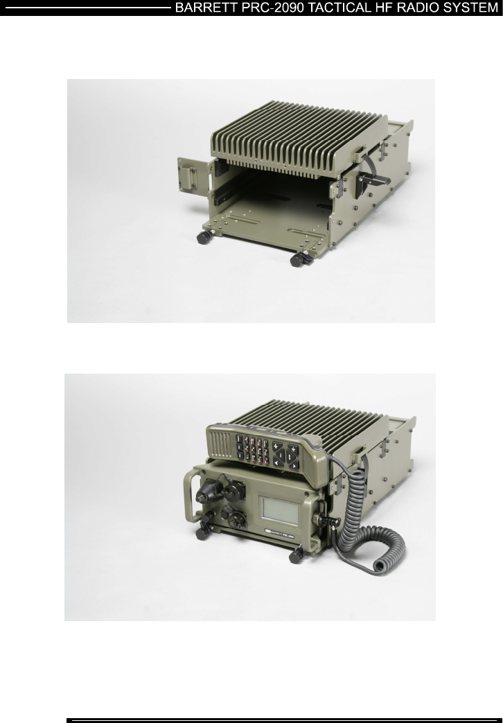
PRC-2090 Tactical HF Transcevier and Docking Station (2090-05-00)
Front View - 2090 Not Fitted
Front View - 2090 Docked
255 of 285
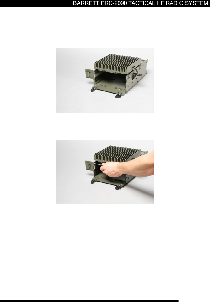
Steps for Docking the PRC-2090 Transceiver into the Docking Station
1) Select where the handset clip is to be placed. The clip can be placed on the
side of the docking station or on the top of the docking station. The clip can
only be moved when the PRC-2090 transceiver is not fitted.
Side mount handset clip
To put the handset clip on top of the docking station unscrew the 2 screws holding
the handset clip.