Barrot Technology IVTI40E Bluetooth Module User Manual
IVT Corporation Bluetooth Module
UserManual.wiki
>
Barrot Technology
>
IVTI40E User Manual
user manual
Navigation menu
Upload a User Manual
Namespaces
Wiki Guide
HTML
PDF
Info
Views
User Manual
Discussion / Help
Navigation

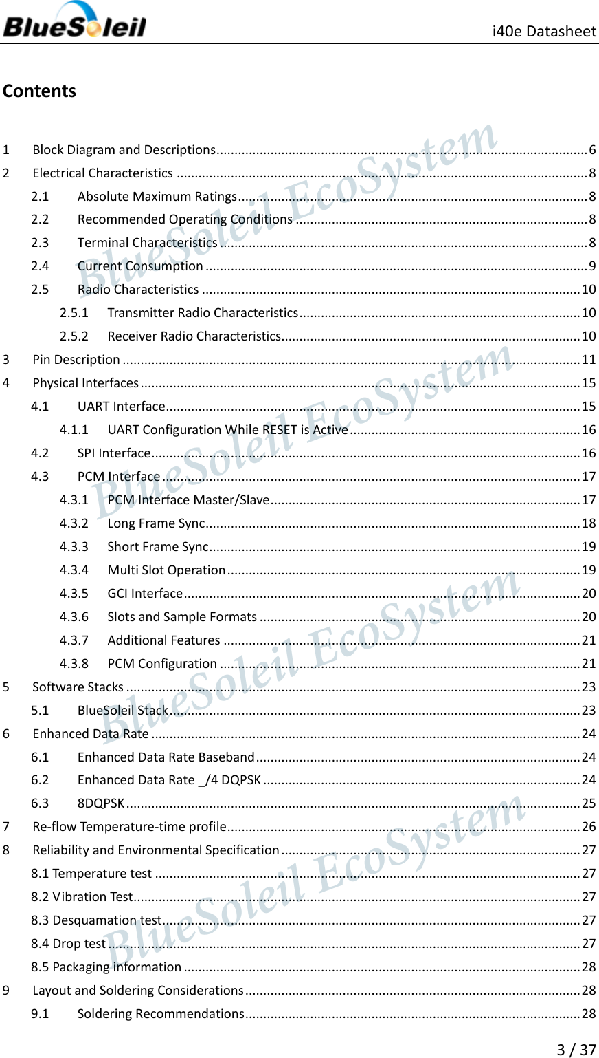
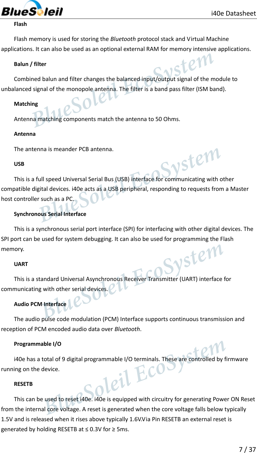
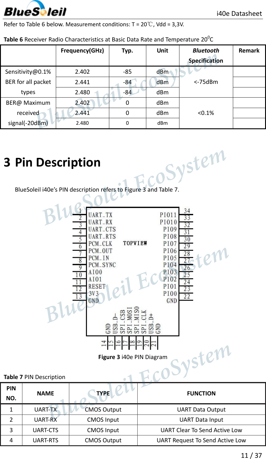
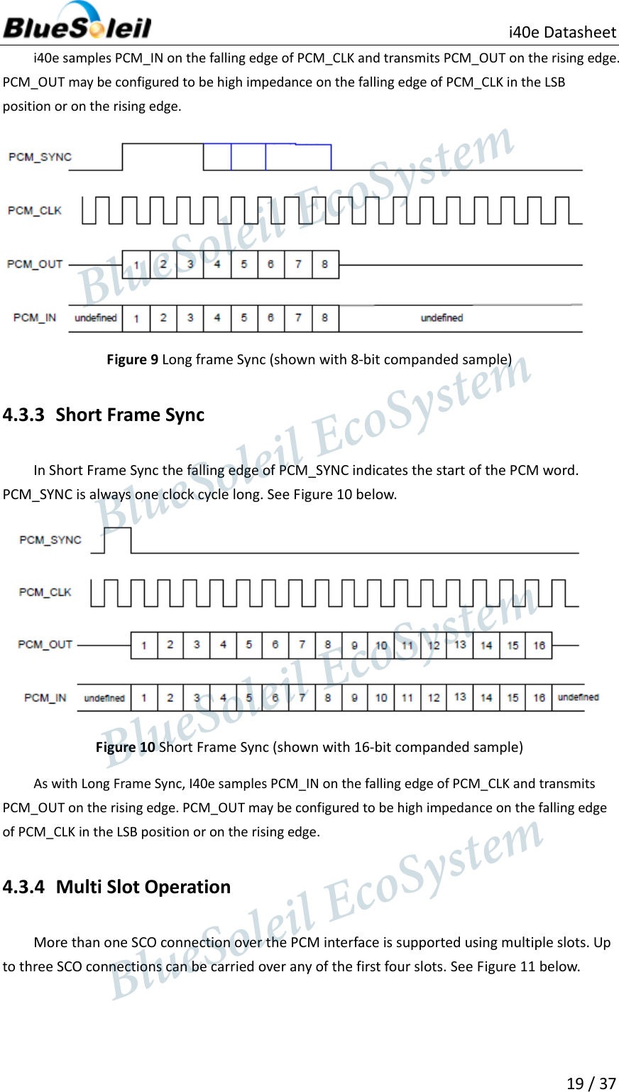
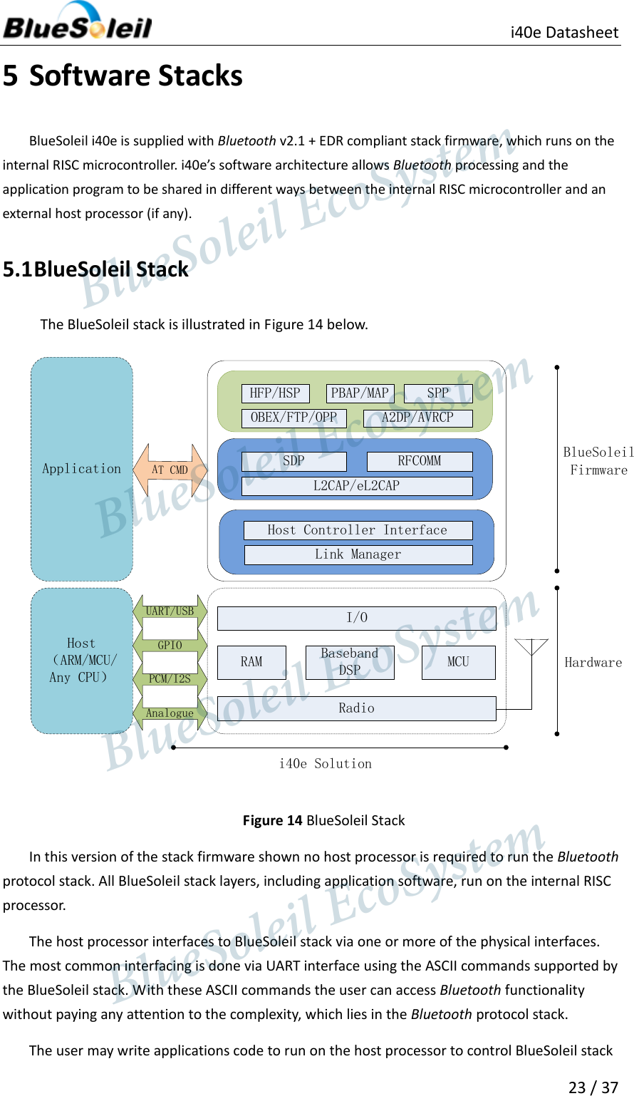
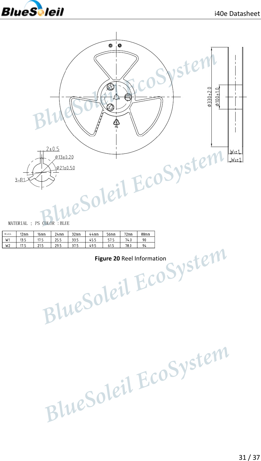
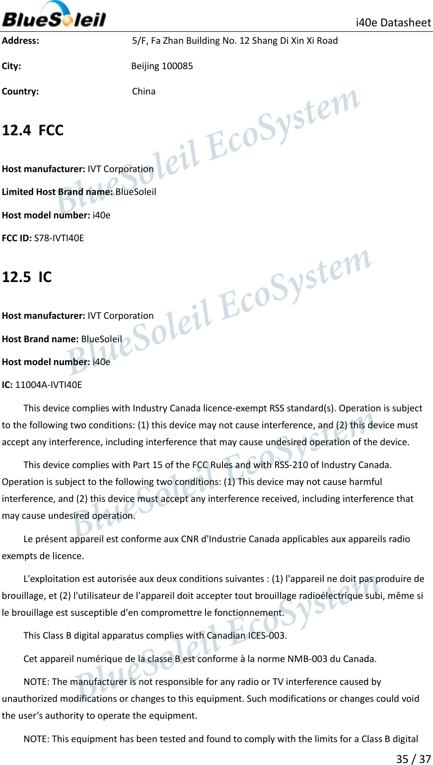
![i40e Datasheet 22 / 37 - 3 Set to 0 SIGN EXTENDED EN 4 0 selects padding of 8 or 13-bit voice sample into a 16- bit slot by inserting extra LSBs, 1 selects sign extension. When padding is selected with 3-bit voice sample, the 3 padding bits are the audio gain setting; with 8-bit samples the 8 padding bits are zeroes. LSB FIRST EN 5 0 transmits and receives voice samples MSB first, 1 uses LSB first. TX TRISTATE EN 6 0 drives PCM_OUT continuously, 1 tri-states PCM_OUT immediately after the falling edge of PCM_CLK in the last bit of an active slot, assuming the next slot is not active. TX TRISTATE RISING EDGE EN 7 0 tristates PCM_OUT immediately after the falling edge of PCM_CLK in the last bit of an active slot, assuming the next slot is also not active. 1 tristates PCM_OUT after the rising edge of PCM_CLK. SYNC SUPPRESS EN 8 0 enables PCM_SYNC output when master, 1 suppresses PCM_SYNC whilst keeping PCM_CLK running. Some CODECS utilize this to enter a low power state. GCI MODE EN 9 1 enables GCI mode. MUTE EN 10 1 forces PCM_OUT to 0. 48M PCM CLK GEN EN 11 0 sets PCM_CLK and PCM_SYNC generation via DDS from internal 4 MHz clock, as for BlueCore4-External. 1 sets PCM_CLK and PCM_SYNC generation via DDS from internal 48 MHz clock. LONG LENGTH SYNC EN 12 0 sets PCM_SYNC length to 8 PCM_CLK cycles and 1 sets length to 16 PCM_CLK cycles. Only applies for long frame sync and with 48M_PCM_CLK_GEN_EN set to 1. - [20:16] Set to 0b00000. MASTER CLK RATE [22:21] Selects 128 (0b01), 256 (0b00), 512 (0b10) kHz PCM_CLK frequency when master and 48M_PCM_CLK_GEN_EN (bit 11) is low. ACTIVE SLOT [26:23] Default is 0001. Ignored by firmware SAMPLE_FORMAT [28:27] Selects between 13 (0b00), 16 (0b01), 8 (0b10) bit sample with 16 cycle slot duration 8 (0b11) bit sample 8 cycle slot duration. Table 10 PSKEY_PCM_LOW_JITTER_CONFIG Description Name Bit position Description CNT LIMIT [12:0] Sets PCM_CLK counter limit CNT RATE [23:16] Sets PCM_CLK count rate. SYNC LIMIT [31:24] Sets PCM_SYNC division relative to PCM_CLK. BlueSoleil EcoSystem BlueSoleil EcoSystem BlueSoleil EcoSystemBlueSoleil EcoSystem](https://usermanual.wiki/Barrot-Technology/IVTI40E/User-Guide-2217282-Page-22.png)