Barrot Technology IVTI40E Bluetooth Module User Manual
IVT Corporation Bluetooth Module
user manual

i40e Datasheet
2 / 37
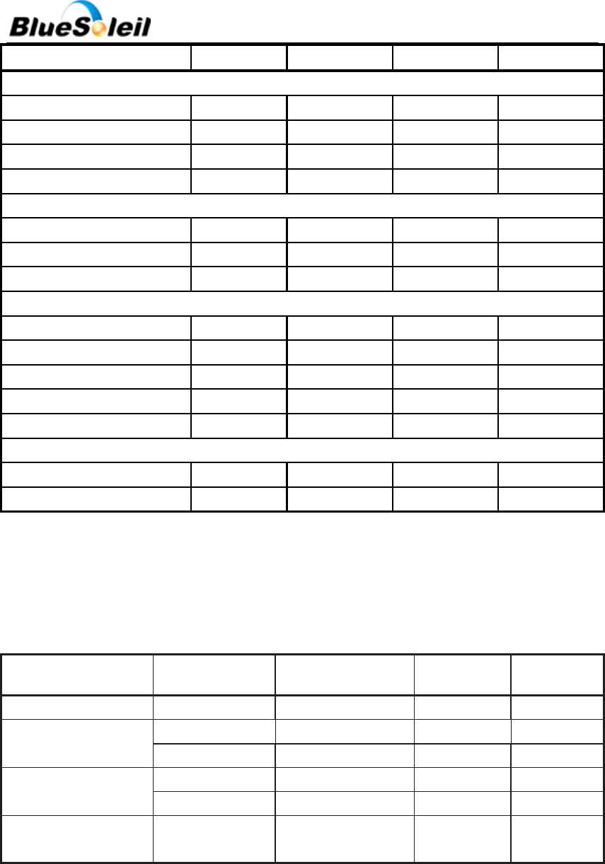
VERSION HISTORY
REVISION
AMENDMENT
DATE
AUTHOR
1.0
Initial version
2012-06-25
Wang Yuqiang
Zhu Yong
1.1
Added certification, contact
information, copyright
2012-08-06
Zhu Yong
Huang Ruixue
1.2
Format update
2012-11-28
Li Li
1.3
Update package information.
Refer to the chapter 11.
2012-12-12
Li Li
1.4
Add FCC & IC number
2014-2-20
Li Li
BlueSoleil EcoSystem
BlueSoleil EcoSystem
BlueSoleil EcoSystem
BlueSoleil EcoSystem

i40e Datasheet
3 / 37
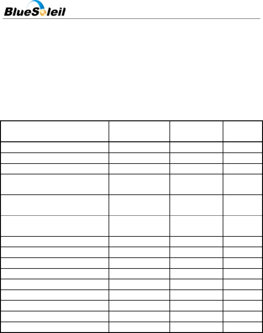
Contents
1 Block Diagram and Descriptions ....................................................................................................... 6
2 Electrical Characteristics .................................................................................................................. 8
2.1 Absolute Maximum Ratings ................................................................................................. 8
2.2 Recommended Operating Conditions ................................................................................. 8
2.3 Terminal Characteristics ...................................................................................................... 8
2.4 Current Consumption .......................................................................................................... 9
2.5 Radio Characteristics ......................................................................................................... 10
2.5.1 Transmitter Radio Characteristics .............................................................................. 10
2.5.2 Receiver Radio Characteristics................................................................................... 10
3 Pin Description ............................................................................................................................... 11
4 Physical Interfaces .......................................................................................................................... 15
4.1 UART Interface ................................................................................................................... 15
4.1.1 UART Configuration While RESET is Active ................................................................ 16
4.2 SPI Interface ....................................................................................................................... 16
4.3 PCM Interface .................................................................................................................... 17
4.3.1 PCM Interface Master/Slave ...................................................................................... 17
4.3.2 Long Frame Sync ........................................................................................................ 18
4.3.3 Short Frame Sync ....................................................................................................... 19
4.3.4 Multi Slot Operation .................................................................................................. 19
4.3.5 GCI Interface .............................................................................................................. 20
4.3.6 Slots and Sample Formats ......................................................................................... 20
4.3.7 Additional Features ................................................................................................... 21
4.3.8 PCM Configuration .................................................................................................... 21
5 Software Stacks .............................................................................................................................. 23
5.1 BlueSoleil Stack .................................................................................................................. 23
6 Enhanced Data Rate ....................................................................................................................... 24
6.1 Enhanced Data Rate Baseband .......................................................................................... 24
6.2 Enhanced Data Rate _/4 DQPSK ........................................................................................ 24
6.3 8DQPSK .............................................................................................................................. 25
7 Re-flow Temperature-time profile .................................................................................................. 26
8 Reliability and Environmental Specification ................................................................................... 27
8.1 Temperature test ...................................................................................................................... 27
8.2 Vibration Test ............................................................................................................................ 27
8.3 Desquamation test .................................................................................................................... 27
8.4 Drop test ................................................................................................................................... 27
8.5 Packaging information .............................................................................................................. 28
9 Layout and Soldering Considerations ............................................................................................. 28
9.1 Soldering Recommendations ............................................................................................. 28
BlueSoleil EcoSystem
BlueSoleil EcoSystem
BlueSoleil EcoSystem
BlueSoleil EcoSystem

i40e Datasheet
4 / 37
9.2 Layout Guidelines .............................................................................................................. 28
10 Physical Dimensions ....................................................................................................................... 29
11 Package .......................................................................................................................................... 30
12 Certification .................................................................................................................................... 32
12.1 Bluetooth ........................................................................................................................... 32
12.2 Korea KCC .......................................................................................................................... 33
12.3 Japan TELEC ....................................................................................................................... 34
12.4 Bluetooth Technology Best Developed Corporation ......................................................... 35
13 Contacts ......................................................................................................................................... 36
14 Copyright ........................................................................................................................................ 37
BlueSoleil EcoSystem
BlueSoleil EcoSystem
BlueSoleil EcoSystem
BlueSoleil EcoSystem
i40e Datasheet
5 / 37
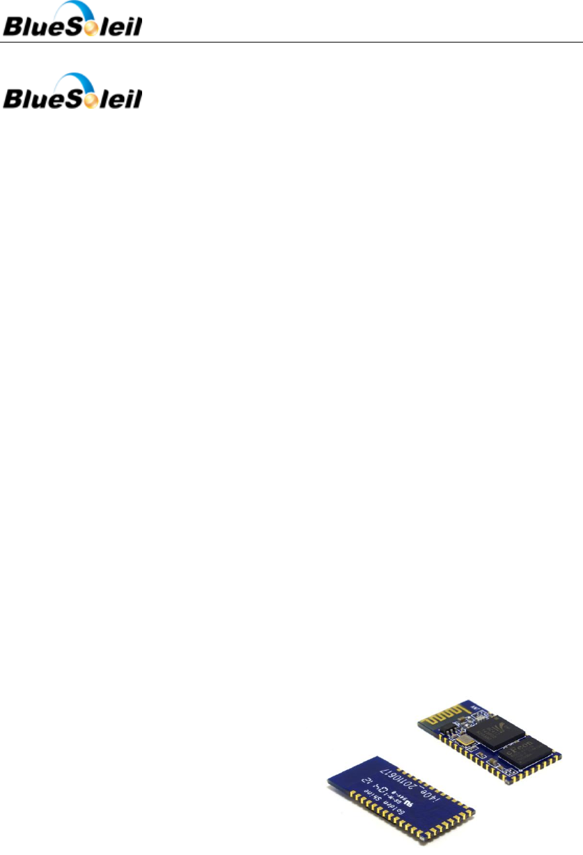
i40e
DESCRIPTION
BlueSoleil i40e is a Bluetooth 2.1 +EDR
(Enhanced Data Rates) Class 2 module. i40e
contains all the necessary elements from
Bluetooth radio to antenna, and a fully
implemented protocol stack.
By default, i40e module is equipped with
powerful and easy-to-use BlueSoleil firmware.
BlueSoleil firmware enables users to access
Bluetooth functionality with simple ASCII
commands delivered to the module over serial
interface - it's just like a Bluetooth modem.
Therefore, i40e provides an ideal solution for
developers who rapidly want to integrate
Bluetooth wireless technology into their design.
FEATURES
Fully Qualified Bluetooth system v2.1 +
EDR,
BQB, KCC, TELEC
Support both Master and Slave roles
Integrated chip antenna
Industrial temperature range from -400C to
+850C
RoHS Compliant
Support for 802.11 Coexistence
8Mbits of Flash Memory
Low power consumption
APPLICATIONS
Cable replacement
Point-of-sales systems
Barcode readers and pay terminals
Telemetry and machine-to-machine
devices
Automotive inspection and measurement
systems
Medical systems
Fitness and sports telemetry devices
Figure 1 BlueSoleil i40e
BlueSoleil EcoSystem
BlueSoleil EcoSystem
BlueSoleil EcoSystem
BlueSoleil EcoSystem
I40e Datasheet
6 / 37
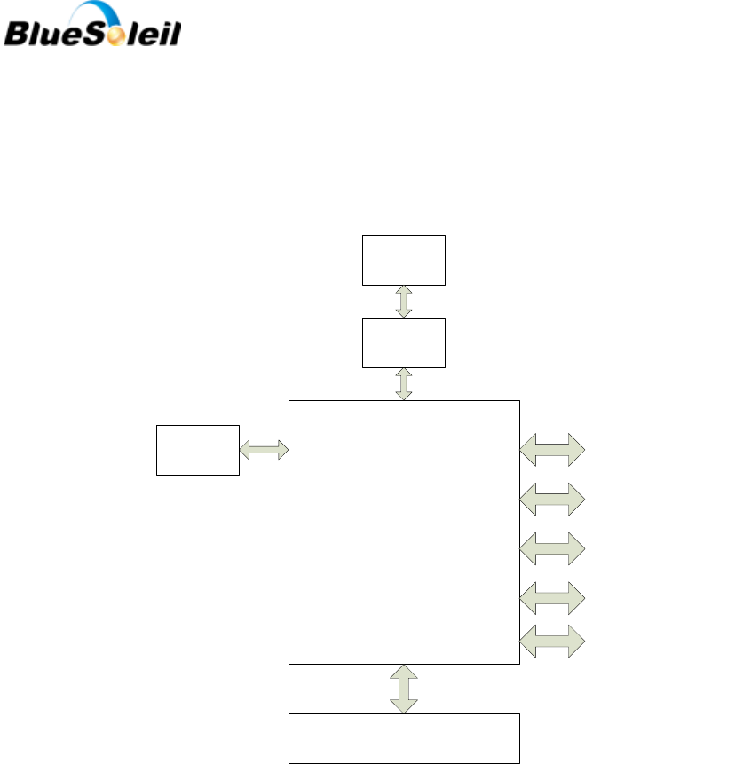
1 Block Diagram and Descriptions
BlueSoleil i40e’s block diagram is illustrated in Figure 2 below.
Bluecore04
EXTFLASH
26M
crystal
8M bit FLASH
BALUN
FILTER
PCB
antenna
USB
UART
SPI
PCM
PIO
Figure 2 i40e Block Diagram
BlueCore04
BlueCore4 is a single chip Bluetooth solution which implements the Bluetooth radio
transceiver and also an on chip microcontroller. BlueCore4 implements Bluetooth® 2.1 + EDR
(Enhanced Data Rate) and it can deliver data rates up to 3 Mbps.
The microcontroller (MCU) on BlueCore04 acts as interrupt controller and event timer run
the BlueSoleil stack and control the radio and host interfaces. A 16-bit reduced instruction set
computer (RISC) microcontroller is used for low power consumption and efficient use of memory.
BlueCore04 has 48Kbytes of on-chip RAM is provided to support the RISC MCU and is shared
between the ring buffers used to hold voice/data for each active connection and the general
purpose memory required by the BlueSoleil stack.
Crystal
The crystal oscillates at 26MHz.
BlueSoleil EcoSystem
BlueSoleil EcoSystem
BlueSoleil EcoSystem
BlueSoleil EcoSystem

i40e Datasheet
7 / 37
Flash
Flash memory is used for storing the Bluetooth protocol stack and Virtual Machine
applications. It can also be used as an optional external RAM for memory intensive applications.
Balun / filter
Combined balun and filter changes the balanced input/output signal of the module to
unbalanced signal of the monopole antenna. The filter is a band pass filter (ISM band).
Matching
Antenna matching components match the antenna to 50 Ohms.
Antenna
The antenna is meander PCB antenna.
USB
This is a full speed Universal Serial Bus (USB) interface for communicating with other
compatible digital devices. i40e acts as a USB peripheral, responding to requests from a Master
host controller such as a PC.
Synchronous Serial Interface
This is a synchronous serial port interface (SPI) for interfacing with other digital devices. The
SPI port can be used for system debugging. It can also be used for programming the Flash
memory.
UART
This is a standard Universal Asynchronous Receiver Transmitter (UART) interface for
communicating with other serial devices.
Audio PCM Interface
The audio pulse code modulation (PCM) Interface supports continuous transmission and
reception of PCM encoded audio data over Bluetooth.
Programmable I/O
i40e has a total of 9 digital programmable I/O terminals. These are controlled by firmware
running on the device.
RESETB
This can be used to reset i40e. i40e is equipped with circuitry for generating Power ON Reset
from the internal core voltage. A reset is generated when the core voltage falls below typically
1.5V and is released when it rises above typically 1.6V.Via Pin RESETB an external reset is
generated by holding RESETB at ≤ 0.3V for ≥ 5ms.
BlueSoleil EcoSystem
BlueSoleil EcoSystem
BlueSoleil EcoSystem
BlueSoleil EcoSystem
i40e Datasheet
8 / 37
802.11 Coexistence Interface
Dedicated hardware is provided to implement a variety of coexistence schemes. Channel
skipping AFH (Adaptive Frequency Hopping), priority signaling, channel signaling and host passing
of channel instructions are all supported. All mentioned features are configured in firmware.
2 Electrical Characteristics
2.1 Absolute Maximum Ratings
The module should not continuously run under extreme conditions. The absolute maximum
ratings are summarized in Table 1 below. Exposure to absolute maximum rating conditions for
extended periods of time may affect reliability and cause permanent damage to the device.
Table 1 Absolute Maximum Ratings
Min
Max
Unit
Storage temperature
-40
85
°C
Operating temperature
-40
85
°C
Supply voltage
-0.3
3.6
V
Terminal voltages
Vss-0.4
Vdd+0.4
V
2.2 Recommended Operating Conditions
Recommended operating conditions are summarized in Table 2 below. BlueSoleil i40e
operates as low as 2.7 V supply voltage. However, to safely meet the USB specification for
minimum voltage for USB data lines, minimum of 3.1 V supply is required.
Table 2 Recommended Operating Conditions
Min
Typ
Max
Unit
Operating temperature
-40
20
85
°C
Supply voltage
3.1
3.3
3.6
V
Terminal voltages
0
-
Vdd
V
2.3 Terminal Characteristics
BlueSoleil i40e’s terminal characteristics are summarized in Table 3 below.
Table 3 Terminal Characteristics
BlueSoleil EcoSystem
BlueSoleil EcoSystem
BlueSoleil EcoSystem
BlueSoleil EcoSystem
i40e Datasheet
9 / 37
Min
Typ
Max
Unit
I/O voltage levels
VIL input logic level low
-0.4
-
0.8
V
VIH input logic level high
0.7Vdd
-
Vdd + 0.4
V
VOL output logic level low
-
-
0,2
V
VOH output logic level high
Vdd -0.2
-
-
V
Reset terminal
VTH,res threshold voltage
0.64
0.85
1.5
V
RIRES input resistance
-
220
-
kΩ
CIRES input capacitance
-
220
-
nF
Input and tri-state current with
Strong pull-up
-100
-40
-10
µA
Strong pull-down
10
40
100
µA
Weak pull-up
-5
-1
-0.2
µA
Weak pull-down
0.2
1
5
µA
I/O pad leakage current
-1
0
1
µA
Vdd supply current
TX mode
-
-
70
mA
RX mode
-
-
70
mA
2.4 Current Consumption
BlueSoleil i40e’s current consumption is summarized in Table 4 below.
Table 4 Current Consumption
Operation Mode
Connection Type
UART Rate (kbps)
Average
Unit
Inquiry and Page scan
-
2.1
mA
ACL No traffic 500ms
Sniff
Slave
9.6
1.9
mA
Master
9.6
1.9
mA
ACL with file transfer
Slave
9.6
22.7
mA
Master
9.6
11.5
mA
Stand by Host
connection(a)
-
-
1.0
mA
BlueSoleil EcoSystem
BlueSoleil EcoSystem
BlueSoleil EcoSystem
BlueSoleil EcoSystem
i40e Datasheet
10 / 37
2.5 Radio Characteristics
2.5.1 Transmitter Radio Characteristics
i40e meets the Bluetooth v2.1 + EDR specification between -40°C and +85°C. TX output is
guaranteed to be unconditionally stable over the guaranteed temperature range. Refer to Table 5
below. Measurement conditions: T = 20℃, Vdd = 3,3V
Table 5 Transmitter Radio Characteristics at Basic Data Rate and Temperature 20℃
Item
Typical Value
Bluetooth
Specification
Unit
Maximum output power1,2
+2.5
-6 to 43
dBm
RF power control range
35
≧16
dB
20dB bandwidth for modulated carrier
780
≦1000
kHz
Adjacent channel transmit power
F = F0 ± 2MHz
-40
≦ 20
dBm
Adjacent channel transmit power
F = F0 ± 3MHz
-45
-40
dBm
Adjacent channel transmit power
F = F0 ± > 3MHz
-50
-40
dBm
Δf1avg Maximum Modulation
165
140<f1avg<175
kHz
Δf2max Maximum Modulation
150
115
kHz
Δf1avg / Δf2avg
0.97
≧0.80
-
Initial carrier frequency tolerance
6
≦75
kHz
Drift Rate
8
≦20
kHz/50µs
Drift (single slot packet)
7
≦ 25
kHz
Drift (five slot packet)
9
≦ 40
kHz
2nd Harmonic content
-65
≦ -30
dBm
3rd Harmonic content
-45
≦ -30
dBm
NOTES:
1. I40E firmware maintains the transmit power to be within the Bluetooth v2.1 + EDR
specification limits.
2. Measurement made using a PSKEY_LC_MAX_TX_POWER setting corresponds to a
PSKEY_LC_POWER_TABLE power table entry of 63.
2.5.2 Receiver Radio Characteristics
RX input is guaranteed to be unconditionally stable over the guaranteed temperature range.
BlueSoleil EcoSystem
BlueSoleil EcoSystem
BlueSoleil EcoSystem
BlueSoleil EcoSystem
i40e Datasheet
11 / 37
Refer to Table 6 below. Measurement conditions: T = 20℃, Vdd = 3,3V.
Table 6 Receiver Radio Characteristics at Basic Data Rate and Temperature 200C
Frequency(GHz)
Typ.
Unit
Bluetooth
Specification
Remark
Sensitivity@0.1%
BER for all packet
types
2.402
-85
dBm
<-75dBm
2.441
-84
dBm
2.480
-84
dBm
BER@ Maximum
received
signal(-20dBm)
2.402
0
dBm
<0.1%
2.441
0
dBm
2.480
0
dBm
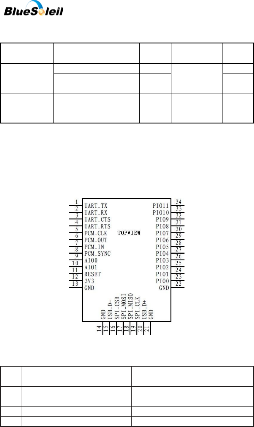
3 Pin Description
BlueSoleil i40e’s PIN description refers to Figure 3 and Table 7.
Figure 3 i40e PIN Diagram
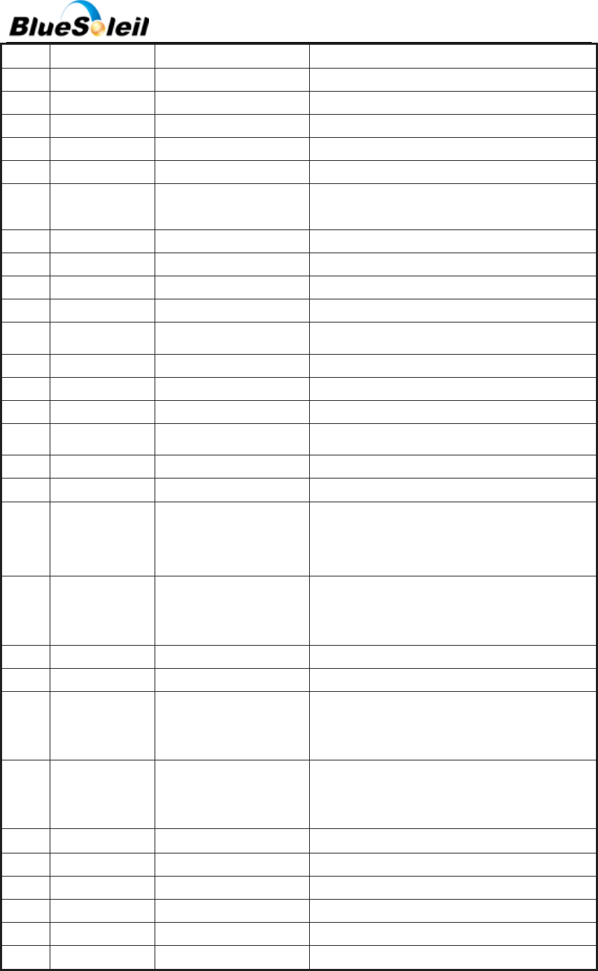
Table 7 PIN Description
PIN
NO.
NAME
TYPE
FUNCTION
1
UART-TX
CMOS Output
UART Data Output
2
UART-RX
CMOS Input
UART Data Input
3
UART-CTS
CMOS Input
UART Clear To Send Active Low
4
UART-RTS
CMOS Output
UART Request To Send Active Low
BlueSoleil EcoSystem
BlueSoleil EcoSystem
BlueSoleil EcoSystem
BlueSoleil EcoSystem
i40e Datasheet
12 / 37
5
PCM-CLK
Bi-directional
Synchronous Data Clock
6
PCM-OUT
CMOS Output
Synchronous Data Output
7
PCM-IN
CMOS Input
Synchronous Data Input
8
PCM-SYNC
Bi-directional
Synchronous Data Sync
9
AIO(0)
Bi-directional
Programmable Input/Output Line
10
AIO(1)
Bi-directional
Programmable Input/Output Line
11
RESETB
CMOS Input
Reset if low. Input debounced so must be low
for >5ms to cause a reset
12
VDD
POWER
+3.3V Supply
13
GND
GND
Ground
14
GND
GND
Ground
15
USBD-
Bi-directional
USB Data Minus
16
SPI-CSB
CMOS Input
Chip Select For Synchronous Serial Interface
17
SPI-MOSI
CMOS Input
Serial Peripheral Interface Data Input
18
SPI-MISO
CMOS Output
Serial Peripheral Interface Data Output
19
SPI-CLK
CMOS Input
Serial Peripheral Interface Clock
20
USB D+
Bi-directional
USB Data Plus with selectable internal 1.5KΩ
21
GND
GND
Ground
22
GND
GND
Ground
23
PIO(0)
Bi-directional with
programmable
strength
Control output for external LNA(if fitted)
24
PIO(1)
Bi-directional with
programmable
strength
Control output for external PA(if fitted)
25
PIO(2)
Bi-directional
Programmable Input/Output Line
26
PIO(3)
Bi-directional
Programmable Input/Output Line
27
PIO(4)
Bi-directional with
programmable
strength
Programmable Input/Output Line or optional
BT_Priority/CH_Clk output for co-existence
28
PIO(5)
Bi-directional with
programmable
strength
Programmable Input/Output Line or optional
BT_Active output for co-existence
29
NC
NC
30
NC
NC
31
NC
NC
32
PIO(9)
Bi-directional
Programmable Input/Output Line
33
PIO(10)
Bi-directional
Programmable Input/Output Line
34
PIO(11)
Bi-directional
Programmable Input/Output Line
BlueSoleil EcoSystem
BlueSoleil EcoSystem
BlueSoleil EcoSystem
BlueSoleil EcoSystem
i40e Datasheet
13 / 37
GND
Connect GND pins to the ground plane of PCB.
VDD
3.3 V supply voltage connection. i40e has an internal decoupling capacitor and LC filter to block
high frequency disturbances. Thus external filtering is usually not needed. It is however recommended
to leave an option for an external high Q 10pF decoupling capacitor in case EMC problems arise.
RESETB
The RESET pin is an active high reset and is internally filtered using the internal low frequency
clock oscillator. A reset will be performed between 1.5 and 4.0ms following RESET being active. It is
recommended that RESET be applied for a period greater than 5ms.
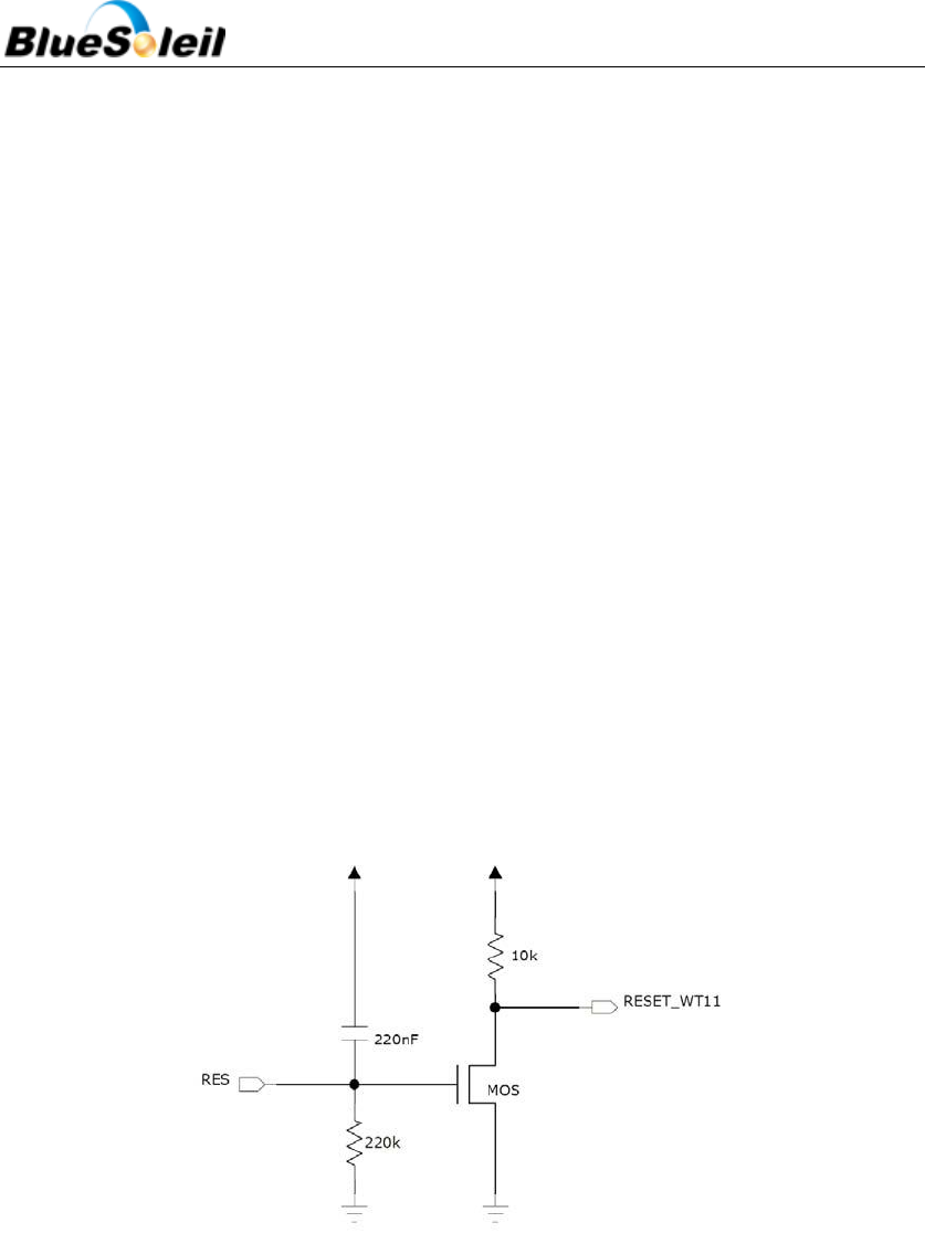
BlueSoleil i40e has an internal reset circuitry, which keeps reset pin active until supply voltage
has reached stability in the start up. See Figure 4below. This ensures that supply for the flash memory
inside the i40e will reach stability before BC4 chip fetches instructions from it. Schematic of the reset
circuitry is shown in figure 4. Rising supply voltage charges the capacitor, which will activate the reset
of i40e. The capacitor discharges through 220k resistor, which eventually deactivates the reset. Time
constant of the RC circuitry is set such that the supply voltage is safely stabilized before reset
deactivates. Pull-up or pull-down resistor should not be connected to the reset pin to ensure proper
star up of i40e.
Figure 4 i40e Internal Reset Circuitry
PIO0 – PIO5, PIO9 –PIO11
Programmable digital I/O lines.
NC
Leave unconnected.
BlueSoleil EcoSystem
BlueSoleil EcoSystem
BlueSoleil EcoSystem
BlueSoleil EcoSystem

i40e Datasheet
14 / 37
RTS
CMOS output with weak internal pull-up. Can be used to implement RS232 hardware flow
control where RTS (request to send) is active low indicator. UART interface requires external RS232
transceiver chip.
CTS
CMOS input with weak internal pull-down. Can be used to implement RS232 hardware flow
control where CTS (clear to send) is active low indicator. UART interface requires external RS232
transceiver chip.
RXD
CMOS input with weak internal pull-down. RXD is used to implement UART data transfer from
another device to i40e.
TXD
CMOS output with weak internal pull-up. TXD is used to implement UART data transfer from i40e
to another device.
PCM_OUT
CMOS output with weak internal pull-down. Used in PCM (pulse code modulation) interface to
transmit digitized audio.
PCM_IN
CMOS input with weak internal pull-down. Used in PCM interface to receive digitized audio.
PCM_CLK
Bi-directional synchronous data clock signal pin with weak internal pull-down. PCM_CLK is used
in PCM interface to transmit or receive CLK signal. When configured as a master, i40e generates clock
signal for the PCM interface. When configured as a slave PCM_CLK is an input and receives the clock
signal from another device.
PCM_SYNC
Bi-directional synchronous data strobe with weak internal pull-down. When configured as a
master, i40e generates SYNC signal for the PCM interface. When configured as a slave PCM_SYNC is an
input and receives the SYNC signal from another device.
USB_D+
Bi-directional USB data line with a selectable internal 1.5 -up implemented as a current
source (compliant with USB specification v1.2) External series resistor is required to match the
connection to the characteristic impedance of the USB cable.
USB_D-
BlueSoleil EcoSystem
BlueSoleil EcoSystem
BlueSoleil EcoSystem
BlueSoleil EcoSystem
i40e Datasheet
15 / 37
Bi-directional USB data line. External series resistor is required to match the connection to the
characteristic impedance of the USB cable.
SPI_CSB
CMOS input with weak internal pull-up. Active low chip select for SPI (serial peripheral interface).
SPI_CLK
CMOS input for the SPI clock signal with weak internal pull-down. i40e is the slave and receives
the clock signal from the device operating as a master.
SPI_MISO
SPI data output with weak internal pull-down.
SPI_MOSI
SPI data input with weak internal pull-down.
4 Physical Interfaces
4.1 UART Interface
BlueSoleil i40e Universal Asynchronous Receiver Transmitter (UART) interface provides a simple
mechanism for communicating with other serial devices using the RS232 standard. i40e’s UART
interface uses voltage levels of 0 to Vdd and thus external transceiver IC is required to meet the
voltage level specifications of UART.
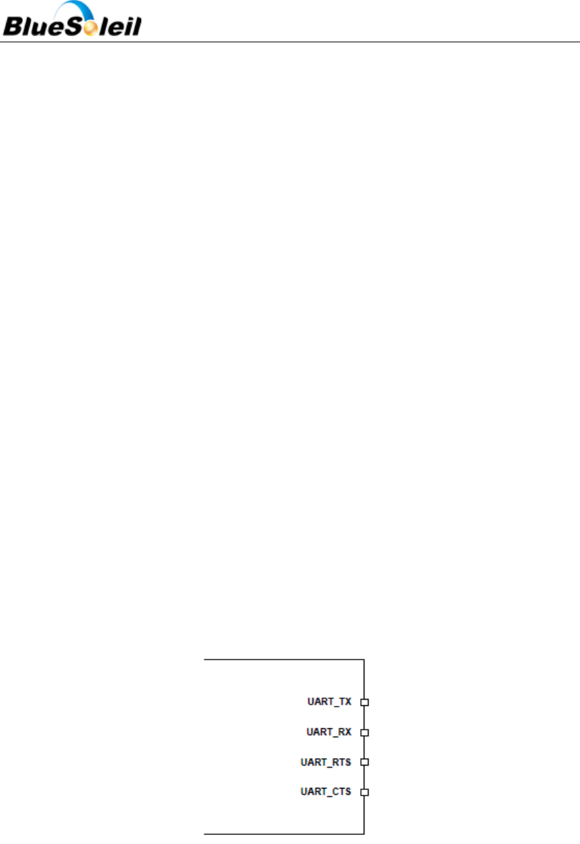
Figure 5 i40e UART Interface
Four signals are used to implement the UART function, as shown in Figure 5 above. When i40e is
connected to another digital device, UART_RX and UART_TX transfer data between the two devices.
The remaining two signals, UART_CTS and UART_RTS, can be used to implement RS232 hardware flow
control where both are active low indicators. All UART connections are implemented using CMOS
technology and have signaling levels of 0V and VDD.
BlueSoleil EcoSystem
BlueSoleil EcoSystem
BlueSoleil EcoSystem
BlueSoleil EcoSystem
i40e Datasheet
16 / 37
In order to communicate with the UART at its maximum data rate using a standard PC, an
accelerated serial port adapter card is required for the PC. The possible UART settings are summarized
in Table 8 below.
Table 8 Possible UART Settings
UART Parameters
Possible Values
Baud rate
Minimum
1200 baud (≤2%Error)
9600 baud (≤1%Error)
Maximum
3.0Mbaud (≤1%Error)
Flow control
RTS/CTS, none
Parity
None, Odd, Even
Number of stop bits
1 or 2
Bits per channel
8
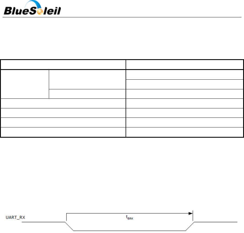
The UART interface is capable of resetting i40e upon reception of a break signal. A Break is
identified by a continuous logic low (0V) on the UART_RX terminal, as shown in Figure 5. If tBRK is
longer than the value, defined by the PS Key PSKEY_HOST_IO_UART_RESET_TIMEOUT(0x1a4), a
reset will occur. This feature allows a host to initialize the system to a known state. Also, i40e can
emit a Break character that may be used to wake the Host. See Figure 6 below.
Figure 6 Break Signal
Since UART_RX terminal includes weak internal pull-down, it can’t be left open unless disabling
UART interface using PS_KEY settings. If UART is not disabled, a pull-up resistor has to be connected to
UART_RX. UART interface requires external RS232 transceiver, which usually includes the required
pull-up.
4.1.1 UART Configuration While RESET is Active
The UART interface for i40e while the chip is being held in reset is tri-state. This will allow the
user to daisy chain devices onto the physical UART bus. The constraint on this method is that any
devices connected to this bus must tri-state when i40e reset is de-asserted and the firmware begins to
run.
4.2 SPI Interface
The synchronous serial port interface (SPI) is for interfacing with other digital devices. The SPI
port can be used for system debugging. It can also be used for programming the Flash memory. SPI
BlueSoleil EcoSystem
BlueSoleil EcoSystem
BlueSoleil EcoSystem
BlueSoleil EcoSystem

i40e Datasheet
17 / 37
interface is connected using the MOSI, MISO, CSB and CLK pins.
The module operates as a slave and thus MISO is an output of the module. MISO is not in high
impedance state when CSB is pulled high. Instead, the module outputs 0 if the processor is running
and 1 if it is stopped.
4.3 PCM Interface
PCM is a standard method used to digitize audio (particularly voice) for transmission over digital
communication channels. Through its PCM interface, i40e has hardware support for continual
transmission and reception of PCM data, thus reducing processor overhead for wireless headset
applications. i40e offers a bidirectional digital audio interface that routes directly into the baseband
layer of the on-chip firmware. It does not pass through the HCI protocol layer.
Hardware on i40e allows the data to be sent to and received from a SCO connection. Up to three
SCO connections can be supported by the PCM interface at any one time.
i40e can operate as the PCM interface master generating an output clock of 128, 256 or
512kHz.When configured as PCM interface slave, it can operate with an input clock up to 2048KHz.
i40e is compatible with a variety of clock formats, including Long Frame Sync, Short Frame Sync and
GCI timing environments.
It supports 13-bit or 16-bit linear, 8-bit µ-law or A-law companded sample formats at
8ksamples/s and can receive and transmit on any selection of three of the first four slots following
PCM_SYNC. The PCM configuration options are enabled by setting PSKEY_PCM_CONFIG32(0x1b3).
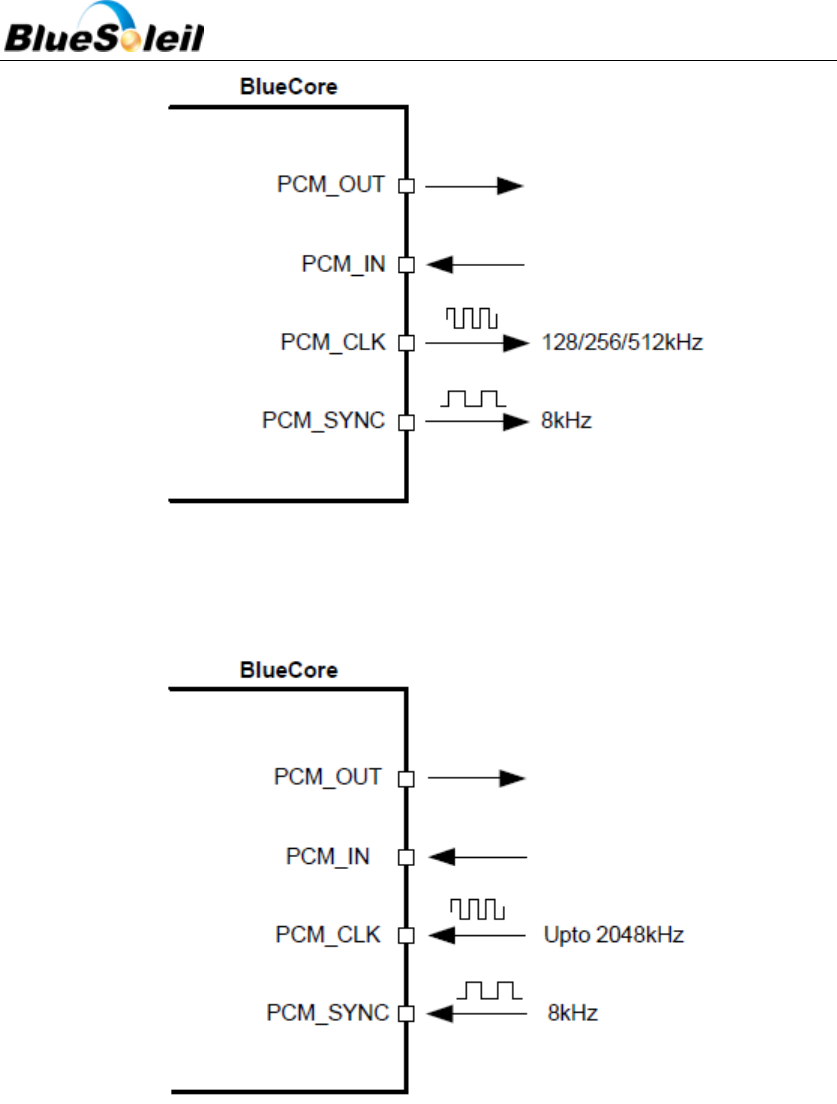
4.3.1 PCM Interface Master/Slave
When configured as the Master of the PCM interface, i40e generates PCM_CLK and PCM_SYNC.
See Figure 7 below.
BlueSoleil EcoSystem
BlueSoleil EcoSystem
BlueSoleil EcoSystem
BlueSoleil EcoSystem
i40e Datasheet
18 / 37
Figure 7 i40e as PCM Master
When configured as the Slave of the PCM interface, i40e accepts PCM_CLK and PCM_SYNC.
PCM_CLK rates up to 2048kHz are accepted. See Figure 8 below.
Figure 8 i40e as PCM Slave
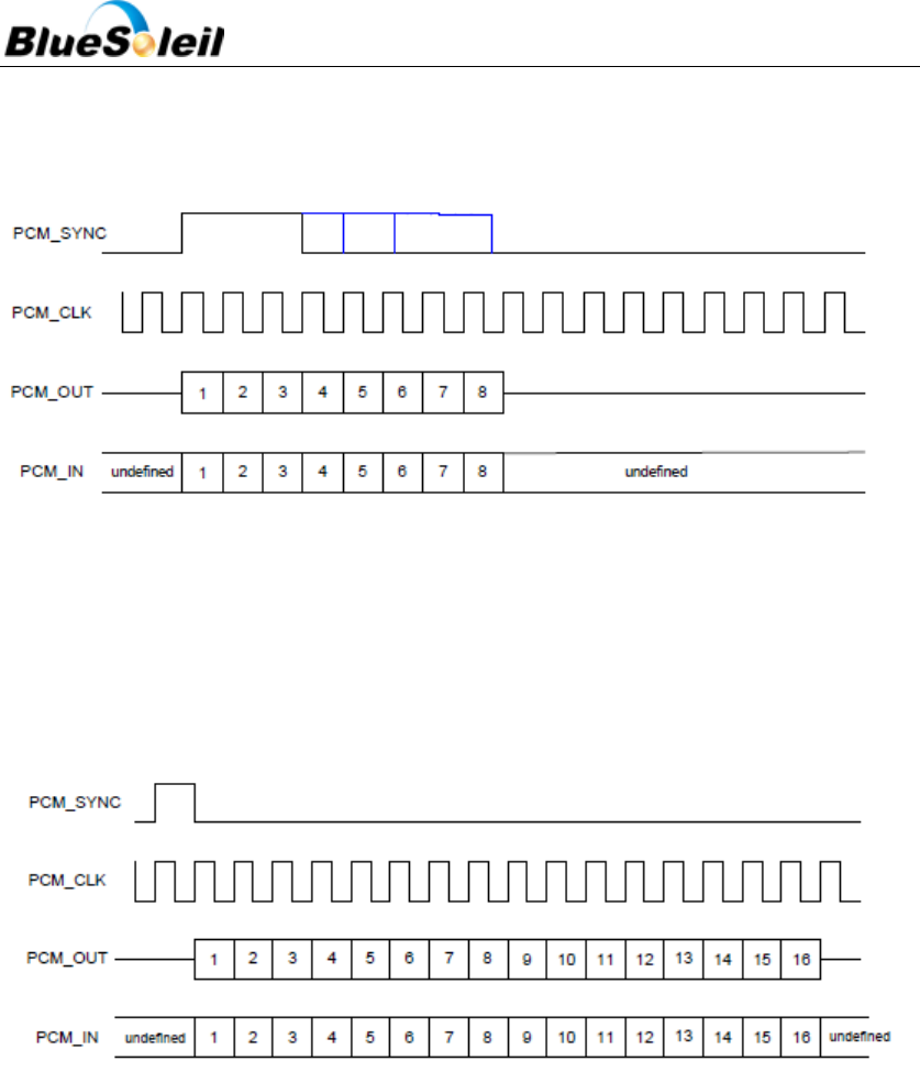
4.3.2 Long Frame Sync
Long Frame Sync is the name given to a clocking format that controls the transfer of PCM data
words or samples. In Long Frame Sync, the rising edge of PCM_SYNC indicates the start of the PCM
word. When i40e is configured as PCM Master, generating PCM_SYNC and PCM_CLK, then PCM_SYNC
is 8-bits long. When BlueCore4-External is configured as PCM Slave, PCM_SYNC may be from two
consecutive falling edges of PCM_CLK to half the PCM_SYNC rate, i.e. 62.5µs long. See Figure 9 below.
BlueSoleil EcoSystem
BlueSoleil EcoSystem
BlueSoleil EcoSystem
BlueSoleil EcoSystem
i40e Datasheet
19 / 37
i40e samples PCM_IN on the falling edge of PCM_CLK and transmits PCM_OUT on the rising edge.
PCM_OUT may be configured to be high impedance on the falling edge of PCM_CLK in the LSB
position or on the rising edge.
Figure 9 Long frame Sync (shown with 8-bit companded sample)
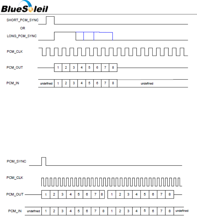
4.3.3 Short Frame Sync
In Short Frame Sync the falling edge of PCM_SYNC indicates the start of the PCM word.
PCM_SYNC is always one clock cycle long. See Figure 10 below.
Figure 10 Short Frame Sync (shown with 16-bit companded sample)
As with Long Frame Sync, I40e samples PCM_IN on the falling edge of PCM_CLK and transmits
PCM_OUT on the rising edge. PCM_OUT may be configured to be high impedance on the falling edge
of PCM_CLK in the LSB position or on the rising edge.
4.3.4 Multi Slot Operation
More than one SCO connection over the PCM interface is supported using multiple slots. Up
to three SCO connections can be carried over any of the first four slots. See Figure 11 below.
BlueSoleil EcoSystem
BlueSoleil EcoSystem
BlueSoleil EcoSystem
BlueSoleil EcoSystem
i40e Datasheet
20 / 37
Figure 11 Multi Slot Operation (shown with two slots and 8-bit companded samples)
4.3.5 GCI Interface
i40e is compatible with the General Circuit Interface, a standard synchronous 2B+D ISDN timing
interface. The two 64Kbps B channels can be accessed when this mode is configured. See Figure 12
below.
Figure 12 GCI Interface
The start of frame is indicated by the rising edge of PCM_SYNC and runs at 8K Hz. With i40e in
Slave mode, the frequency of PCM_CLK can be up to 4.096MHz.
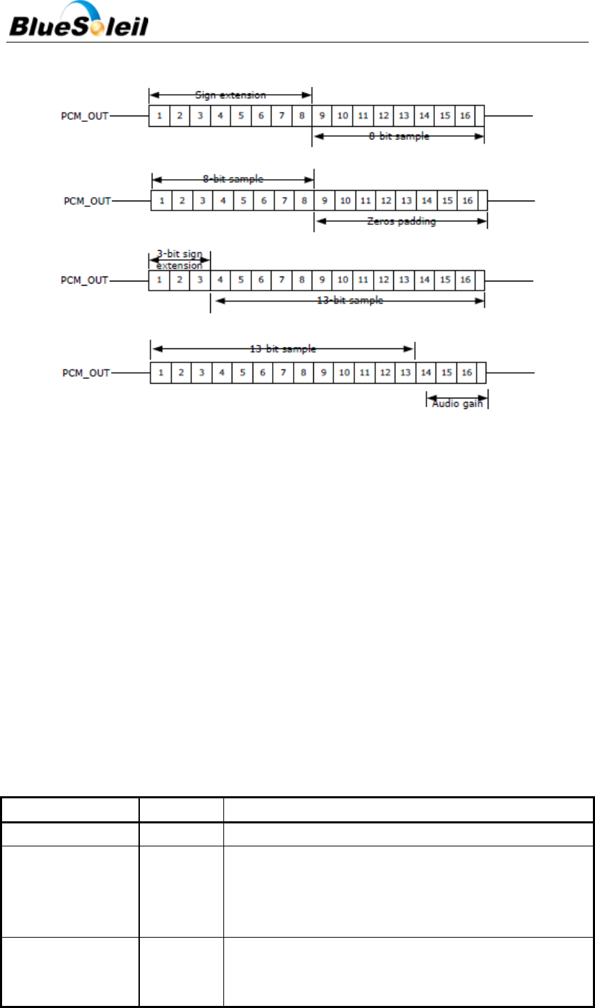
4.3.6 Slots and Sample Formats
i40e can receive and transmit on any selection of the first four slots following each sync
pulse. Slot durations can be either 8 or 16 clock cycles. Duration’s of 8 clock cycles may only be
used with 8-bit sample formats. Durations of 16 clocks may be used with 8, 13 or 16-bit sample
formats.
i40e supports 13-bit linear, 16-bit linear and 8-bit µ-law or A-law sample formats. The
sample rate is 8ksamples/s. The bit order may be little or big endian. When 16-bit slots are used,
the 3 or 8 unused bits in each slot may be filled with sign extension, padded with zeros or a
programmable 3-bit audio attenuation compatible with some Motorola CODECs. See Figure 13
BlueSoleil EcoSystem
BlueSoleil EcoSystem
BlueSoleil EcoSystem
BlueSoleil EcoSystem
i40e Datasheet
21 / 37
below.
Figure 13 16-bit Slot with 13-bit Linear Sample and Audio Gain Selected
4.3.7 Additional Features
i40e has a mute facility that forces PCM_OUT to be 0. In Master mode, PCM_SYNC may also be
forced to 0 while keeping PCM_CLK running which some CODECS use to control power down.
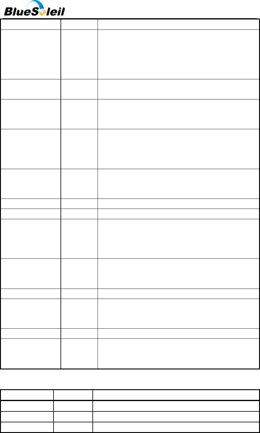
4.3.8 PCM Configuration
The PCM configuration is set using two PS Keys, PSKEY_PCM_CONFIG32 and
PSKEY_PCM_LOW_JITTER_CONFIG. They are summarized in Table 9 and Table 10below. The default
for PSKEY_PCM_CONFIG32 key is 0x00800000 i.e. first slot following sync is active, 13-bit linear voice
format, long frame sync and interface master generating 256kHz PCM_CLK from 4MHz internal clock
with no tri-stating of PCM_OUT.
Table 9 PSKEY_PCM_CONFIG32 Description
Name
Bit position
Description
-
0
Set to 0
SLAVE MODE EN
1
0 selects Master mode with internal generation of
PCM_CLK and PCM_SYNC. 1 selects Slave mode requiring
externally generated PCM_CLK and PCM_SYNC. This should
be set to 1 if 48M_PCM_CLK_GEN_EN (bit 11) is set.
SHORT SYNC EN
2
0 selects long frame sync (rising edge indicates start of
frame), 1 selects short frame sync (falling edge indicates
start of frame).
BlueSoleil EcoSystem
BlueSoleil EcoSystem
BlueSoleil EcoSystem
BlueSoleil EcoSystem
i40e Datasheet
22 / 37
-
3
Set to 0
SIGN EXTENDED EN
4
0 selects padding of 8 or 13-bit voice sample into a 16- bit
slot by inserting extra LSBs, 1 selects sign extension. When
padding is selected with 3-bit voice sample, the 3 padding
bits are the audio gain setting; with 8-bit samples the 8
padding bits are zeroes.
LSB FIRST EN
5
0 transmits and receives voice samples MSB first, 1 uses
LSB first.
TX TRISTATE EN
6
0 drives PCM_OUT continuously, 1 tri-states PCM_OUT
immediately after the falling edge of PCM_CLK in the last
bit of an active slot, assuming the next slot is not active.
TX TRISTATE RISING
EDGE EN
7
0 tristates PCM_OUT immediately after the falling edge of
PCM_CLK in the last bit of an active slot, assuming the next
slot is also not active. 1 tristates PCM_OUT after the rising
edge of PCM_CLK.
SYNC SUPPRESS EN
8
0 enables PCM_SYNC output when master, 1 suppresses
PCM_SYNC whilst keeping PCM_CLK running. Some
CODECS utilize this to enter a low power state.
GCI MODE EN
9
1 enables GCI mode.
MUTE EN
10
1 forces PCM_OUT to 0.
48M PCM CLK GEN
EN
11
0 sets PCM_CLK and PCM_SYNC generation via DDS from
internal 4 MHz clock, as for BlueCore4-External. 1 sets
PCM_CLK and PCM_SYNC generation via DDS from internal
48 MHz clock.
LONG LENGTH SYNC
EN
12
0 sets PCM_SYNC length to 8 PCM_CLK cycles and 1 sets
length to 16 PCM_CLK cycles. Only applies for long frame
sync and with 48M_PCM_CLK_GEN_EN set to 1.
-
[20:16]
Set to 0b00000.
MASTER CLK RATE
[22:21]
Selects 128 (0b01), 256 (0b00), 512 (0b10) kHz PCM_CLK
frequency when master and 48M_PCM_CLK_GEN_EN (bit
11) is low.
ACTIVE SLOT
[26:23]
Default is 0001. Ignored by firmware
SAMPLE_FORMAT
[28:27]
Selects between 13 (0b00), 16 (0b01), 8 (0b10) bit sample
with 16 cycle slot duration 8 (0b11) bit sample 8 cycle slot
duration.
Table 10 PSKEY_PCM_LOW_JITTER_CONFIG Description
Name
Bit position
Description
CNT LIMIT
[12:0]
Sets PCM_CLK counter limit
CNT RATE
[23:16]
Sets PCM_CLK count rate.
SYNC LIMIT
[31:24]
Sets PCM_SYNC division relative to PCM_CLK.
BlueSoleil EcoSystem
BlueSoleil EcoSystem
BlueSoleil EcoSystem
BlueSoleil EcoSystem
i40e Datasheet
23 / 37
5 Software Stacks
BlueSoleil i40e is supplied with Bluetooth v2.1 + EDR compliant stack firmware, which runs on the
internal RISC microcontroller. i40e’s software architecture allows Bluetooth processing and the
application program to be shared in different ways between the internal RISC microcontroller and an
external host processor (if any).
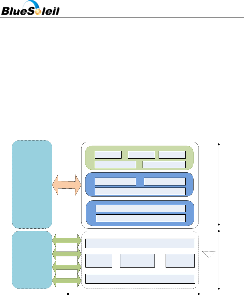
5.1 BlueSoleil Stack
The BlueSoleil stack is illustrated in Figure 14 below.
Radio
RAM
I/O
Host
(ARM/MCU/
Any CPU)
UART/USB
BlueSoleil
Firmware
Hardware
L2CAP/eL2CAP
SDP RFCOMM
OBEX/FTP/OPP
HFP/HSP PBAP/MAP
A2DP/AVRCP
MCU
Baseband
DSP
Link Manager
Host Controller Interface
GPIO
PCM/I2S
Analogue
AT CMD
Application
SPP
i40e Solution
Figure 14 BlueSoleil Stack
In this version of the stack firmware shown no host processor is required to run the Bluetooth
protocol stack. All BlueSoleil stack layers, including application software, run on the internal RISC
processor.
The host processor interfaces to BlueSoleil stack via one or more of the physical interfaces.
The most common interfacing is done via UART interface using the ASCII commands supported by
the BlueSoleil stack. With these ASCII commands the user can access Bluetooth functionality
without paying any attention to the complexity, which lies in the Bluetooth protocol stack.
The user may write applications code to run on the host processor to control BlueSoleil stack
BlueSoleil EcoSystem
BlueSoleil EcoSystem
BlueSoleil EcoSystem
BlueSoleil EcoSystem
i40e Datasheet
24 / 37
with ASCII commands and to develop Bluetooth applications. Please refer to BlueSoleil i40e’s
programming manuals: BlueSoleil_i40e_SPP_programming_manual.pdf or
BlueSoleil_i40e_Multi_programming_manual.pdf.
6 Enhanced Data Rate
EDR has been introduced to provide 2x and optionally 3x data rates with minimal disruption to
higher layers of the Bluetooth stack. CSR supports both of the new data rates, with i40e. i40e is
compliant with revision v2.0.E.2 of the specification.
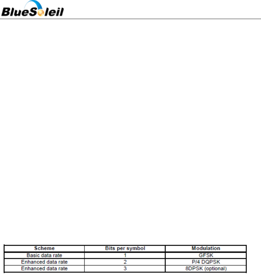
6.1 Enhanced Data Rate Baseband
At the baseband level EDR uses the same 1.6kHz slot rate as basic data rate and therefore the
packets can be 1, 3, or 5 slots long as per the basic data rate. Where EDR differs from the basic data
rate is that in the same 1MHz symbol rate 2 or 3bits are used per symbol, compared to 1bit per
symbol used by the basic data rate. To achieve the increase in number of bits symbol, two new
modulation schemes have been introduced as summarized in Table 11 below, and the modulation
schemes are explained in the further sections.
Table 11 Data Rate Schemes
Although the EDR uses new packets Link establishment and management are unchanged and still
use Basic Rate packets.
6.2 Enhanced Data Rate _/4 DQPSK
4 DQPSK includes the following features:
4-state Differential Phase Shift Keying.
4-state Differential Phase Shift Keying.
2 bits determine phase shift between consecutive symbols. Refer to Table 12 below.
S/4 rotation avoids phase shift of S, which would cause large amplitude variation.
Raised Cosine pulse shaping filter to further reduce side band emissions.
Table 12 2 bits Determine Phase Shift between Consecutive Symbols
BlueSoleil EcoSystem
BlueSoleil EcoSystem
BlueSoleil EcoSystem
BlueSoleil EcoSystem
i40e Datasheet
25 / 37
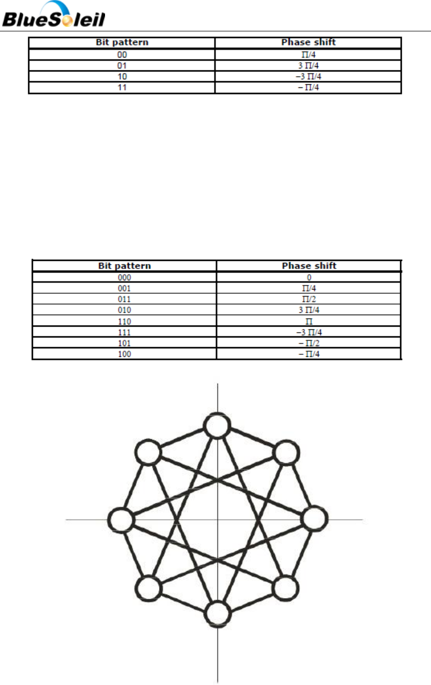
6.3 8DQPSK
8DQPSK includes the following features:
8-state Differential Phase-Shift Keying. Refer to Figure 15 below.
Three bits determine phase shift between consecutive symbols. Refer to Table 13 below.
Table 13 3 bits Determine Phase Shift between Consecutive Symbols
Figure 15 8DQPSK
BlueSoleil EcoSystem
BlueSoleil EcoSystem
BlueSoleil EcoSystem
BlueSoleil EcoSystem
i40e Datasheet
26 / 37
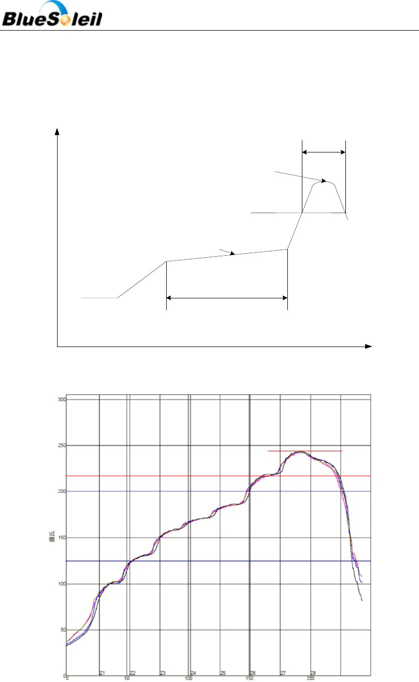
7 Re-flow Temperature-time profile
The re-flow profiles are illustrated in Figure 16 and Figure 17 below.
40+20/-15s
2170C
90+30/-30s
2300C~2450C
1500C~1900C
Temp.(0C)
Time(S)
Figure 16 Typical Lead-free Re-flow Solder Profile
2170C
2420C
Figure 17 Typical Lead-free Re-flow
BlueSoleil EcoSystem
BlueSoleil EcoSystem
BlueSoleil EcoSystem
BlueSoleil EcoSystem

i40e Datasheet
27 / 37
The soldering profile depends on various parameters according to the use of different solder
and material. The data here is given only for guidance on solder re-flow. i40e will withstand up to
two re-flows to a maximum temperature of 245°C.
8 Reliability and Environmental Specification
8.1 Temperature test
Put the module in demo board which uses exit power supply, power on the module and
connect to mobile. Then put the demo in the ‐40℃ space for 1 hour and then move to +85℃
space within 1minute, after 1 hour move back to ‐40℃ space within1 minute. This is 1 cycle. The
cycles are 32 times and the units have to pass the testing.
8.2 Vibration Test
The module is being tested without package. The displacement requests 1.5mm and sample
is vibrated in three directions(X,Y,Z).Vibration frequency set as 0.5G , a sweep rate of 0.1
octave/min from 5Hz to 100Hz last for 90 minutes each direction. Vibration frequency set as 1.5G,
a sweep rate of 0.25 octave/min from 100Hz to 500Hz last for 20 minutes each direction.
8.3 Desquamation test
Use clamp to fix the module, measure the pull of the component in the module, make sure
the module`s soldering is good.
8.4 Drop test
Free fall the module (condition built in a wrapper which can defend ESD) from 150cm height
to cement ground, each side twice, total twelve times.The appearance will not be damaged and
all functions OK.
BlueSoleil EcoSystem
BlueSoleil EcoSystem
BlueSoleil EcoSystem
BlueSoleil EcoSystem

i40e Datasheet
28 / 37
8.5 Packaging information
After unpacking, the module should be stored in environment as follows:
Temperature: 25℃ ± 2℃
Humidity: <60%
No acidity, sulfur or chlorine environment
The module must be used in four days after unpacking.
9 Layout and Soldering Considerations
9.1 Soldering Recommendations
BlueSoleil i40e is compatible with industrial standard reflow profile for Pb-free solders. The
reflow profile used is dependent on the thermal mass of the entire populated PCB, heat transfer
efficiency of the oven and particular type of solder paste used. Consult the datasheet of
particular solder paste for profile configurations.
IVT Corporation will give following recommendations for soldering the module to ensure
reliable solder joint and operation of the module after soldering. Since the profile used is process
and layout dependent, the optimum profile should be studied case by case. Thus following
recommendation should be taken as a starting point guide.
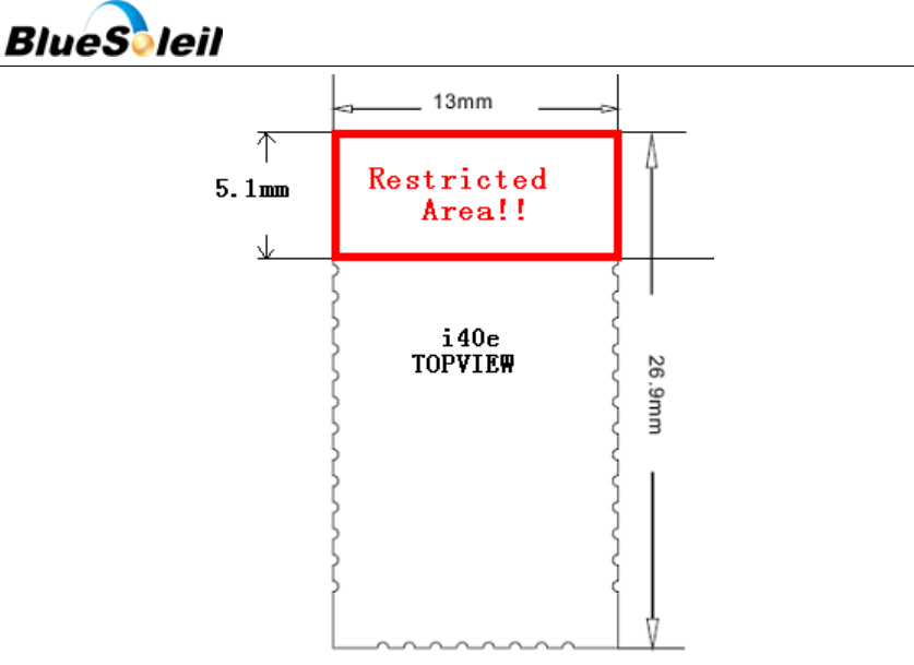
9.2 Layout Guidelines
It is strongly recommended to use good layout practices to ensure proper operation of the
module. Placing copper or any metal near antenna deteriorates its operation by having effect on
the matching properties. Metal shield around the antenna will prevent the radiation and thus
metal case should not be used with the module. Use grounding vias separated max 3 mm apart at
the edge of grounding areas to prevent RF penetrating inside the PCB and causing an
unintentional resonator. Use GND vias all around the PCB edges.
The mother board should have no bare conductors or vias in this restricted area, because it is
not covered by stop mask print. Also no copper (planes, traces or vias) are allowed in this area,
because of mismatching the on-board antenna.
BlueSoleil EcoSystem
BlueSoleil EcoSystem
BlueSoleil EcoSystem
BlueSoleil EcoSystem
i40e Datasheet
29 / 37
Figure 18 i40e Restricted Area
Following recommendations helps to avoid EMC problems arising in the design. Note that
each design is unique and the following list do not consider all basic design rules such as avoiding
capacitive coupling between signal lines. Following list is aimed to avoid EMC problems caused by
RF part of the module. Use good consideration to avoid problems arising from digital signals in
the design.
Ensure that signal lines have return paths as short as possible. For example if a signal goes to
an inner layer through a via, always use ground vias around it. Locate them tightly and
symmetrically around the signal vias. Routing of any sensitive signals should be done in the inner
layers of the PCB. Sensitive traces should have a ground area above and under the line. If this is
not possible, make sure that the return path is short by other means (for example using a ground
line next to the signal line).
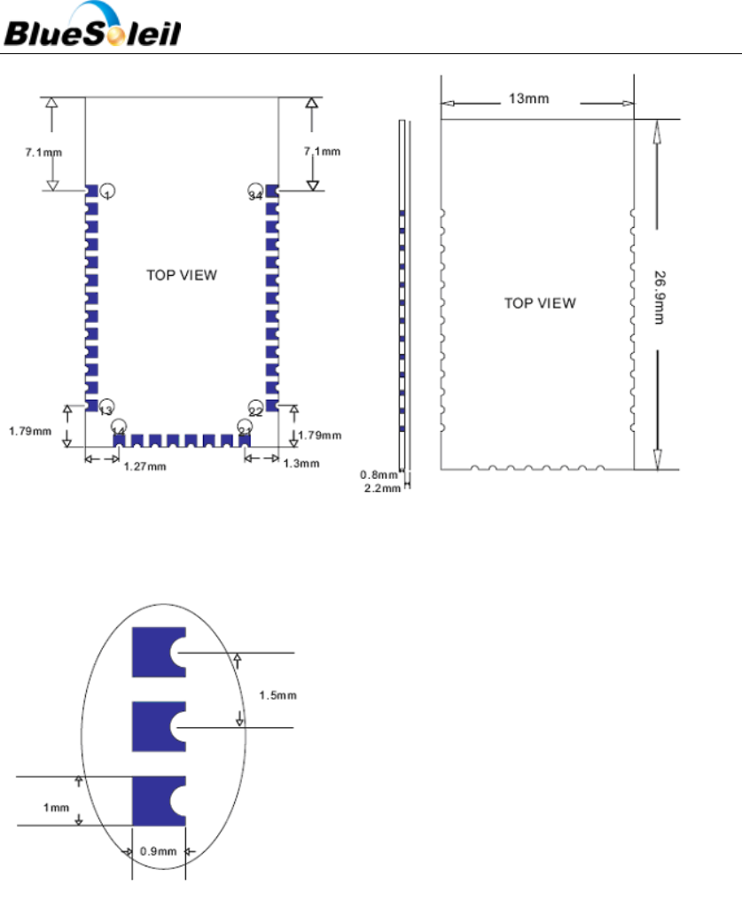
10 Physical Dimensions
BlueSoleil i40e’s dimension is 27mm(L)x13mm(W)x2.2mm(H).
BlueSoleil EcoSystem
BlueSoleil EcoSystem
BlueSoleil EcoSystem
BlueSoleil EcoSystem
i40e Datasheet
32 / 37
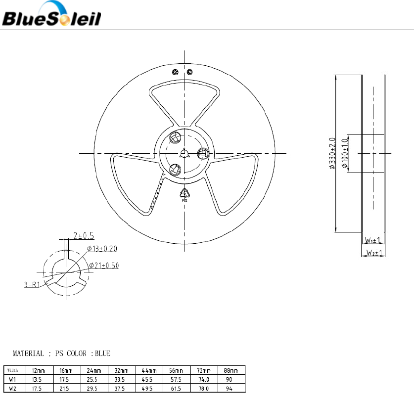
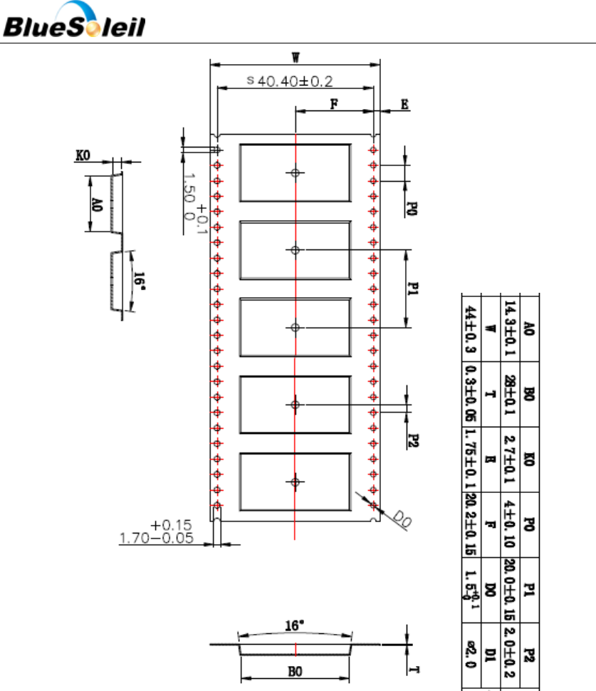
Figure 21 Tape Information
12 Certification
12.1 Bluetooth
BlueSoleil i40e is qualified as a Bluetooth controller subsystem and it fulfills all the mandatory
requirements of Bluetooth 2.1 + EDR core specification. If not modified in any way, it is a complete
Bluetooth entity, containing software and hardware functionality as well as the whole RF-part
including the antenna. This practically translates to that if the module is used without modification of
any kind, it does not need any Bluetooth approval work for evaluation on what needs to be tested.
BlueSoleil EcoSystem
BlueSoleil EcoSystem
BlueSoleil EcoSystem
BlueSoleil EcoSystem
i40e Datasheet
33 / 37
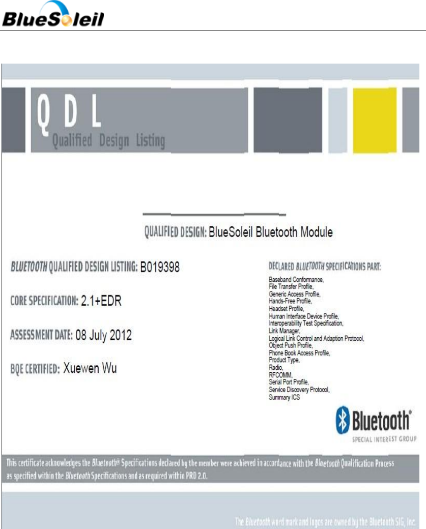
i40e Qualified Design ID (QDID): B019398
Figure 22 B019398 Certificate
12.2 Korea KCC
According to Korean regulations the OEM integrator using a surface mountable module, such as
i40e, will be responsible for re-evaluating the end product (including the transmitter) and obtaining a
separate authorization for the radio. I40e is fully tested to meet the technical requirements of a radio
for Korean market. The declaration is as follows:
Certificate No.: KCC-CRM-iVT-I40e
BlueSoleil EcoSystem
BlueSoleil EcoSystem
BlueSoleil EcoSystem
BlueSoleil EcoSystem
i40e Datasheet
34 / 37
Trade Name or Applicant: IVT Corporation
Equipment Name of the Specified Radio:
Equipment certified by Type Trademark: BlueSoleil
Basic Model Number: i40e
Serial Model Number: N/A
Manufacturer/Country of Origin:
12.3 Japan TELEC
According to Japanese regulations the OEM integrator using a surface mountable module, such
as i40e, will be responsible for re-evaluating the end product (including the transmitter) and obtaining
a separate authorization for the radio. BlueSoleil i40e is fully tested to meet the technical
requirements of a radio for Japanese market. The declaration is as follows:
Certificate No.: 204-240010
PHOENIX TESTLAB GmbH, operating as a Registered Certification Body (RCB ID:204) with respect
to Japan, declares that the listed product complies with the Technical Regulations conformity
Certification of Specified Radio Equipment (ordinance of MPT N0 .37, 1981), Article 2, Paragraph 1,
Item 19.
Product description: Bluetooth 2.1+EDR Module
Trademark/Model Name: BlueSoleil / i40e
Family name: --
Serial No: --
Software Release No: --
Type of emissions: F1D/G1D
Frequency and power: Bluetooth 2.1+EDR:2402~2480MHz;79 ch;0.09 mW/MHz
Manufacturer: IVT Corporation
Address: 5/F, Fa Zhan Building No. 12 Shang Di Xin Xi Road
City: Beijing 100085
Country: China
This Certificate is granted to:
Certificate holder: IVT Corporation
BlueSoleil EcoSystem
BlueSoleil EcoSystem
BlueSoleil EcoSystem
BlueSoleil EcoSystem

i40e Datasheet
35 / 37
Address: 5/F, Fa Zhan Building No. 12 Shang Di Xin Xi Road
City: Beijing 100085
Country: China
12.4 FCC
Host manufacturer: IVT Corporation
Limited Host Brand name: BlueSoleil
Host model number: i40e
FCC ID: S78-IVTI40E
12.5 IC
Host manufacturer: IVT Corporation
Host Brand name: BlueSoleil
Host model number: i40e
IC: 11004A-IVTI40E
This device complies with Industry Canada licence-exempt RSS standard(s). Operation is subject
to the following two conditions: (1) this device may not cause interference, and (2) this device must
accept any interference, including interference that may cause undesired operation of the device.
This device complies with Part 15 of the FCC Rules and with RSS-210 of Industry Canada.
Operation is subject to the following two conditions: (1) This device may not cause harmful
interference, and (2) this device must accept any interference received, including interference that
may cause undesired operation.
Le présent appareil est conforme aux CNR d'Industrie Canada applicables aux appareils radio
exempts de licence.
L'exploitation est autorisée aux deux conditions suivantes : (1) l'appareil ne doit pas produire de
brouillage, et (2) l'utilisateur de l'appareil doit accepter tout brouillage radioélectrique subi, même si
le brouillage est susceptible d'en compromettre le fonctionnement.
This Class B digital apparatus complies with Canadian ICES-003.
Cet appareil numérique de la classe B est conforme à la norme NMB-003 du Canada.
NOTE: The manufacturer is not responsible for any radio or TV interference caused by
unauthorized modifications or changes to this equipment. Such modifications or changes could void
the user’s authority to operate the equipment.
NOTE: This equipment has been tested and found to comply with the limits for a Class B digital
BlueSoleil EcoSystem
BlueSoleil EcoSystem
BlueSoleil EcoSystem
BlueSoleil EcoSystem
i40e Datasheet
36 / 37
device, pursuant to part 15 of the FCC Rules. These limits are designed to provide reasonable
protection against harmful interference in a residential installation. This equipment generates uses
and can radiate radio frequency energy and, if not installed and used in accordance with the
instructions, may cause harmful interference to radio communications. However, there is no
guarantee that interference will not occur in a particular installation. If this equipment does cause
harmful interference to radio or television reception, which can be determined by turning the
equipment off and on, the user is encouraged to try to correct the interference by one or more of the
following measures:
- Reorient or relocate the receiving antenna.
- Increase the separation between the equipment and receiver.
-Connect the equipment into an outlet on a circuit different from that to which the receiver is
connected.
-Consult the dealer or an experienced radio/TV technician for help.
12.6 Bluetooth Technology Best Developed Corporation
IVT Corporation is one of Bluetooth technology BEST developed together which is
authenticated by The Bluetooth SIG. See Figure 23 below.
Figure 23 IVT is One of Bluetooth Technology BEST Developed Together
13 Contacts
Contact: Mr. Zhu Yong
Mobile: +86 18910255873
Tel: +86 10 82898219
Fax: +86 10 62963059
BlueSoleil EcoSystem
BlueSoleil EcoSystem
BlueSoleil EcoSystem
BlueSoleil EcoSystem

i40e Datasheet
37 / 37
Email: embedded@ivtcorporation.com
Address: IVT Corporation. 5/F, Fa Zhan Building No.12, Shang Di Xin Xi Road, Beijing, 100085 P.R. China
Company Site: www.ivtcorporaiton.com
Support: support@ivtcorporation.com
14 Copyright
Copyright © 1999-2012 IVT Corporation
All rights reserved.
IVT Corporation assumes no responsibility for any errors which may appear in the specification.
Furthermore, IVT Corporation reserves the right to alter the hardware, software, and/or specification
detailed here at any time without notice and does not make any commitment to update the
information contained here.
BlueSoleil is a registered trademark of IVT Corporation for Bluetooth production.
The Bluetooth trademark is owned by The Bluetooth SIG Inc., USA and is licensed to IVT Corporation.
All other trademarks listed herein are owned by their respective owners.
BlueSoleil EcoSystem
BlueSoleil EcoSystem
BlueSoleil EcoSystem
BlueSoleil EcoSystem