Barrot Technology IVTI410E Bluetooth module 4.0 LE User Manual
IVT Corporation Bluetooth module 4.0 LE
UserManual.wiki
>
Barrot Technology
>
IVTI410E User Manual
User Manual
Navigation menu
Upload a User Manual
Namespaces
Wiki Guide
HTML
PDF
Info
Views
User Manual
Discussion / Help
Navigation
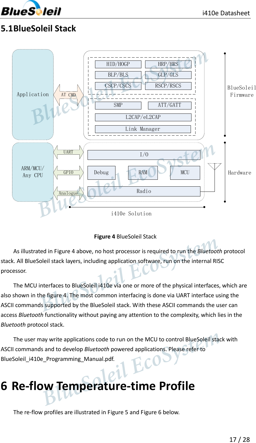
![i410e Datasheet 7 / 28 Flash /EEPROM is used for storing the Bluetooth protocol stack, profile and applications. Low Pass Filter The filter is a band pass filter (ISM band). Antenna The antenna is meander PCB antenna. Synchronous Serial Interface This is a synchronous serial port interface (SPI) for interfacing with other digital devices. The SPI port can be used for system debugging. It can also be used for programming the Flash memory. UART This is a standard Universal Asynchronous Receiver Transmitter (UART) interface for communicating with other serial devices. Programmable I/O I410e has one digital programmable I/O terminal. It is controlled by firmware running on the device. AIO I410e has 3 general-purpose analogue interface pins, AIO[2:0]. PWM I410e contains a PWM module that works in sleep modes. WAKE Wake up input. It wakes i410e from hibernate. 2 Electrical Characteristics 2.1 Absolute Maximum Ratings The module should not continuously run under extreme conditions. The absolute maximum ratings are summarized in Table 1 below. Exposure to absolute maximum rating conditions for extended periods of time may affect reliability and cause permanent damage to the device. Table 1 Absolute Maximum Ratings Rating Min Max Unit BlueSoleil EcoSystem BlueSoleil EcoSystem BlueSoleil EcoSystemBlueSoleil EcoSystem](https://usermanual.wiki/Barrot-Technology/IVTI410E/User-Guide-2010309-Page-7.png)

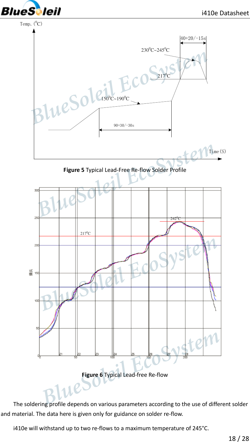
![i410e Datasheet 12 / 28 The hardware supports all optional and mandatory features of Bluetooth v4.0 specification. It performs the following features: Cyclic redundancy check Encryption Data whitening Access code correlation 3 Pin Description BlueSoleil i410e’s PIN descriptions are summarized in Figure 3 and Table 9 below. AIO2AIO1AIO0TXRxPIO3GNDSPI_EN GNDVDD_BATPIO5/SPI_CLKPIO6/SPI_CSBPIO7/SPI_MOSIPIO8/SPI_MISOWAKEGNDTop ViewGNDEXT_ANT Figure 3 i410e PIN diagram Table 9 PIN Description PIN NO. Name Type Function 1 AIO[2] Bidirectional analogue Analogue programmable I/O line. General-purpose analogue interface pins. 2 AIO[1] Bidirectional analogue Analogue programmable I/O line. General-purpose analogue interface pins. 3 AIO[0] Bidirectional analogue Analogue programmable I/O line. General-purpose analogue interface pins. BlueSoleil EcoSystem BlueSoleil EcoSystem BlueSoleil EcoSystemBlueSoleil EcoSystem](https://usermanual.wiki/Barrot-Technology/IVTI410E/User-Guide-2010309-Page-12.png)