Barrot Technology IVTI410E Bluetooth module 4.0 LE User Manual
IVT Corporation Bluetooth module 4.0 LE
User Manual
i410e Datasheet
2 / 28
VERSION HISTORY
REVISION
AMENDMENT
DATE
AUTHOR
1.0
Initial version
2012-10-7
Zhu Yong
1.1
Modify 3, 8, 10 section
2012-10-9
Wan Zhifu
Huang Ruixue
1.2
1. Update power consumption;
2. Change PIO4 to GND.
2012-10-29
Li Li
1.3
1. Update power consumption;
2. Update format.
2012-11-29
Li Li
1.4
Update package information. Refer
to the chapter 10.
2012-12-12
Li Li
1.5
Update Figure 1 BlueSoleil i410e
and Figure 8 i410e Footprint.
2012-12-22
Li Li
1.6
Add FCC, IC, CE certificate
2013-4-3
Li Li
1.7
Add external antenna interface.
2013-4-12
Wan zhifu
Li Li
BlueSoleil EcoSystem
BlueSoleil EcoSystem
BlueSoleil EcoSystem
BlueSoleil EcoSystem

i410e Datasheet
3 / 28
Contents
1 Block Diagram ........................................................................................................................... 6
2 Electrical Characteristics ........................................................................................................... 7
2.1 Absolute Maximum Ratings .......................................................................................... 7
2.2 Recommended Operating Conditions ........................................................................... 8
2.3 Input/output Terminal Characteristics.......................................................................... 8
2.3.1 Switch-mode Regulator ..................................................................................... 8
2.3.2 Low-voltage Linear Regulator ............................................................................ 9
2.3.3 Digital Terminals ................................................................................................ 9
2.3.4 AIO ..................................................................................................................... 9
2.3.5 ESD Protection ................................................................................................. 10
2.4 Current Consumption .................................................................................................. 10
2.5 Radio Characteristics ................................................................................................... 10
2.5.1 RF Ports ........................................................................................................... 10
2.5.2 RF Receiver ...................................................................................................... 11
2.5.3 RF Transmitter ................................................................................................. 11
2.5.4 Bluetooth Radio Synthesizer ............................................................................ 11
2.5.5 Baseband ......................................................................................................... 11
3 Pin Description ........................................................................................................................ 12
4 Physical Interfaces ................................................................................................................... 15
4.1 UART Interface ............................................................................................................ 15
4.2 SPI Interface ................................................................................................................ 15
5 Software Stacks ....................................................................................................................... 16
5.1 BlueSoleil Stack ........................................................................................................... 17
6 Re-flow Temperature-time Profile........................................................................................... 17
7 Reliability and Environmental Specification ............................................................................ 19
7.1 Temperature test ........................................................................................................ 19
7.2 Vibration Test .............................................................................................................. 19
7.3 Desquamation Test ..................................................................................................... 19
7.4 Drop Test ..................................................................................................................... 19
7.5 Packaging Information ................................................................................................ 19
8 Layout and Soldering Considerations ...................................................................................... 20
8.1 Soldering Recommendations ...................................................................................... 20
8.2 Layout Guidelines ........................................................................................................ 20
9 Physical Dimensions ................................................................................................................ 21
10 Package............................................................................................................................ 23
11 Certification ..................................................................................................................... 25
11.1 Bluetooth ................................................................................................................ 25
11.2 CE 0700.................................................................................................................... 25
BlueSoleil EcoSystem
BlueSoleil EcoSystem
BlueSoleil EcoSystem
BlueSoleil EcoSystem

i410e Datasheet
4 / 28
11.3 FCC .......................................................................................................................... 25
11.4 IC ............................................................................................................................. 25
12 Bluetooth Technology Best Developed Corporation ....................................................... 27
13 Contact Information ........................................................................................................ 27
14 Copyright ......................................................................................................................... 28
BlueSoleil EcoSystem
BlueSoleil EcoSystem
BlueSoleil EcoSystem
BlueSoleil EcoSystem
i410e Datasheet
5 / 28
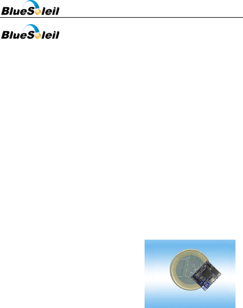
i410e
DESCRIPTION
BlueSoleil i410e is a Bluetooth 4.0
single-mode module. It provides a Bluetooth
Low Energy fully compliant system for data
communication with IVT BlueSoleil stack. It
allows your target devices to send and receive
data via Bluetooth 4.0 without connecting a
serial cable to your computer.
By default, i410e module is equipped with
powerful and easy-to-use BlueSoleil firmware.
It’s easy-to-use and completely encapsulated.
BlueSoleil enables users to access Bluetooth
functionality with simple ASCII commands
delivered to the module over serial interface -
it's just like a Bluetooth modem.
Therefore, BlueSoleil i410e provides an ideal
solution for developers who want to integrate
Bluetooth wireless technology into their
design.
FEATURES
Fully Qualified Bluetooth system v4.0
Low energy
Support Master or Slave roles
Integrated layout antenna
Industrial temperature range from -400C
to +850C
RoHS Compliant
APPLICATIONS
Cable replacement
Sports and fitness
Healthcare
Home entertainment
Office and mobile accessories
Automotive
Commercial
Watches
Human interface devices
Figure 1 BlueSoleil i410e
BlueSoleil EcoSystem
BlueSoleil EcoSystem
BlueSoleil EcoSystem
BlueSoleil EcoSystem
i410e Datasheet
6 / 28
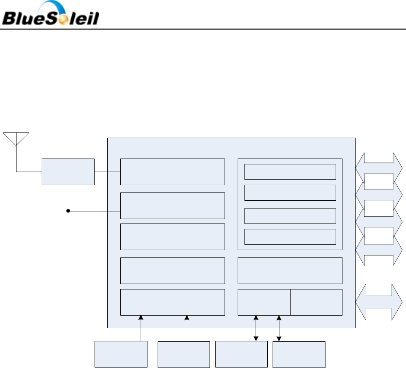
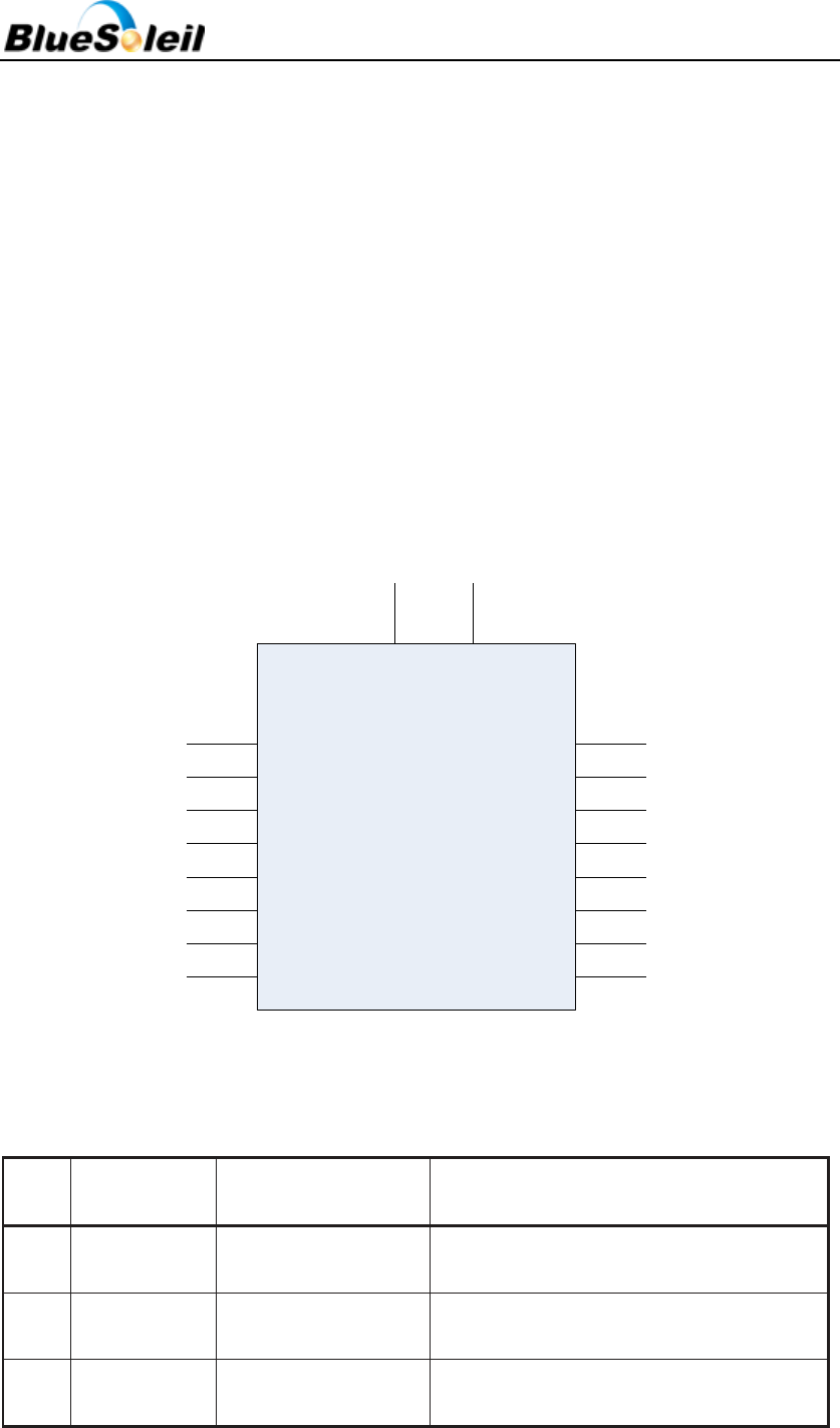
1 Block Diagram
BlueSoleil i410e’s block diagram is illustrated in Figure 2 below.
Debug
MCU
ROM
RAM
Clock Generation I2C SPI
Bluetooth LE
Radio and Modem UART
LED PWM
PIO
AIO
EEPROM/
Flash
SPI
AIO
PIO
PWM
UART
32.768K
Crystal
16M
Crystal
WAKE
Low Pass
Filter
CSR1000
i8002
Figure 2 i410e Block Diagram
CSR1000
CSR1000 is a single chip Bluetooth 4.0 solution which implements the Bluetooth radio
transceiver and also an on chip microcontroller. CSR1000 implements Bluetooth 4.0 and it can
deliver data rates up to 3 Mbps.
The microcontroller (MCU) on CSR1000 acts as interrupt controller and event timer run the
BlueSoleil stack and control the radio and host interfaces. A 16-bit RISC microcontroller is used
for low power consumption and efficient use of memory.
CSR1000 has 64Kbytes of on-chip RAM. it supports the RISC MCU and is shared between the
ring buffers used to hold data for each active connection and the general-purpose memory
required by the BlueSoleil stack.
Crystal
The crystal oscillates include 16MHz and 32.768 KHz. 16MHz is external reference clock
source. 32.768 KHz is used during deep sleep and in other low-power modes.
EEPROM/Flash/i8002
BlueSoleil EcoSystem
BlueSoleil EcoSystem
BlueSoleil EcoSystem
BlueSoleil EcoSystem

i410e Datasheet
7 / 28
Flash /EEPROM is used for storing the Bluetooth protocol stack, profile and applications.
Low Pass Filter
The filter is a band pass filter (ISM band).
Antenna
The antenna is meander PCB antenna.
Synchronous Serial Interface
This is a synchronous serial port interface (SPI) for interfacing with other digital devices. The
SPI port can be used for system debugging. It can also be used for programming the Flash
memory.
UART
This is a standard Universal Asynchronous Receiver Transmitter (UART) interface for
communicating with other serial devices.
Programmable I/O
I410e has one digital programmable I/O terminal. It is controlled by firmware running on the
device.
AIO
I410e has 3 general-purpose analogue interface pins, AIO[2:0].
PWM
I410e contains a PWM module that works in sleep modes.
WAKE
Wake up input. It wakes i410e from hibernate.
2 Electrical Characteristics
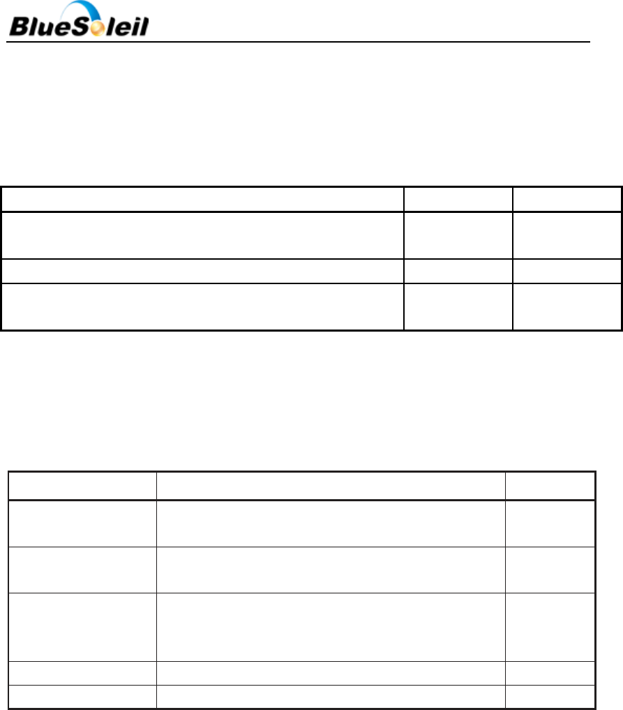
2.1 Absolute Maximum Ratings
The module should not continuously run under extreme conditions. The absolute maximum
ratings are summarized in Table 1 below. Exposure to absolute maximum rating conditions for
extended periods of time may affect reliability and cause permanent damage to the device.
Table 1 Absolute Maximum Ratings
Rating
Min
Max
Unit
BlueSoleil EcoSystem
BlueSoleil EcoSystem
BlueSoleil EcoSystem
BlueSoleil EcoSystem
i410e Datasheet
8 / 28
Storage temperature
-40
85
℃
Battery (VDD_BAT)operation
1.8
3.6
V
I/O supply voltage
-0.4
3.6
V
Other terminal voltages
VSS-0.4
VDD+0.4
V
2.2 Recommended Operating Conditions
Recommended operating conditions are summarized in Table 2 below.
Table 2 Recommended Operating Conditions
Min
Typ
Max
Unit
Operating temperature
-30
20
85
°C
Battery(VDD_BAT) Operation
1.8
-
3.6
V
I/O supply
voltage(VDD_PADS)
1.2
-
3.6
V
.
2.3 Input/output Terminal Characteristics
2.3.1 Switch-mode Regulator
Table 3 Switch-mode Regulator
Min
Typ.
Max
Unit
Switch-mode Regulator
input voltage
1.8
-
3.6
V
Output voltage
0.65
1.35
1.35
V
Temperature coefficient
-200
-
200
ppm/0C
Normal Operation
Output noise, Frequency
range 100Hz to 100KHz
-
-
0.4
mV rms
Setting time, setting to within
10% of final value
-
-
30
µs
Output current(Imax)
-
-
50
mA
Quiescent current(excluding
load, Iload<1mA)
-
-
20
µA
Ultra Low-power Mode
Output current(Imax)
-
-
100
µA
BlueSoleil EcoSystem
BlueSoleil EcoSystem
BlueSoleil EcoSystem
BlueSoleil EcoSystem
i410e Datasheet
9 / 28
Quiescend current
-
-
1
µA
2.3.2 Low-voltage Linear Regulator
Table 4 Switch-mode Regulator
Normal Operation
Min
Typ.
Max
Unit
Input voltage
0.65
-
1.35
V
Output voltage
0.65
-
1.20
V
2.3.3 Digital Terminals
Table 5 Digital Terminals
Min
Typ.
Max
Unit
Input Voltage Levels
VIL input Logic level low
-0.4
-
0.4
V
VIH input logic level high
0.7*VDD
-
VDD+0.4
V
Tr/Tf
-
-
25
ns
Output Voltage Levels
VOL output logic level low, IOL =
4.0mA
-
-
0.4
V
VOH output logic level high,
IOH=-4.0mA
0.75*VDD
-
-
V
Tf/Tf
-
-
5
ns
Input and Tristate Currents
With strong pull-up
-150
-40
-10
µA
I2C with strong pull-up
-250
-
-
µA
With strong pull-down
10
40
150
µA
With weak pull-up
-5.0
-1.0
-0.33
µA
With weak pull-down
0.33
1.0
5.0
µA
CI input capacitance
1.0
-
5.0
pF
2.3.4 AIO
Table 6 AIO
Input Voltage Levels
Min
Typ.
Max
Unit
Input voltage
0
-
1.3
V
BlueSoleil EcoSystem
BlueSoleil EcoSystem
BlueSoleil EcoSystem
BlueSoleil EcoSystem
i410e Datasheet
10 / 28
2.3.5 ESD Protection
Apply ESD static handling precautions during manufacturing. ESD handling maximum ratings
are summarized in Table 7 below.
Table 7 ESD Handling Maximum Ratings
Condition
Max
Unit
Human body model contact discharge per JEDEC
EIA/JESD22-A114
2
2000V(all pins)
Machine model contact Discharge per JEDEC EIA/JESD22-A115
200V
200V(all pings)
Charged Device Model Contact Discharge per JEDEC
EIA/JESD22-C101
III
500V(all pins)
2.4 Current Consumption
Table 8 Current Consumption
Operation Mode
Description
Average
Dormant
All functions are shutdown. To wake up toggle the wake
pin.
5~6uA
Hibernate
VDD_PADS=ON, REFCLK=OFF, SLEEPCLK+ON,
VDD_BAT=ON
5~6µA
Deep Sleep
VDD_PADS=ON, REFCLK=OFF, SLEEPCLK=ON,
VDD_BAT=ON, RAM=ON, digital circuits=ON,
SMPs=ON(low-power mode), 1ms wake-up time
7~8µA
Connected Standby
-
~1.2mA
RX/TX active
-
~ 4mA
2.5 Radio Characteristics
2.5.1 RF Ports
BlueSoleil i410e contains an integrated balun which provides a single-ended RF TX / RX port
pin. No matching components are needed as the receive mode impedance is 50Ω and the
transmitter has been optimized to deliver power in to a 50Ω load.
BlueSoleil EcoSystem
BlueSoleil EcoSystem
BlueSoleil EcoSystem
BlueSoleil EcoSystem

i410e Datasheet
11 / 28
2.5.2 RF Receiver
The receiver features a near-zero IF architecture that allows the channel filters to be
integrated onto the die. Sufficient out-of-band blocking specification at the LNA input allows the
receiver to be used in close proximity to GSM and W‑CDMA cellular phone transmitters without
being significantly desensitized.
An ADC digitizes the IF received signal.
Low Noise Amplifier
The LNA operates in differential mode and takes its input from the balanced port of the
integrated balun.
RSSI Analogue to Digital Converter
The ADC samples the RSSI voltage on a packet-by-packet basis and implements a fast AGC.
The front-end LNA gain is changed according to the measured RSSI value, keeping the first mixer
input signal within a limited range. This improves the dynamic range of the receiver, improving
performance in interference-limited environments.
2.5.3 RF Transmitter
IQ Modulator
The transmitter features a direct IQ modulator to minimize frequency drift during a transmit
packet, which results in a controlled modulation index. Digital baseband transmit circuitry
provides the required spectral shaping.
Power Amplifier
The internal PA has a maximum 7.5dBm output power without needing an external RF PA.
2.5.4 Bluetooth Radio Synthesizer
The Bluetooth radio synthesizer is fully integrated onto the die with no requirement for an
external VCO screening, can varactor tuning diodes, LC resonators or loop filter. The synthesizer is
guaranteed to lock in sufficient time across the guaranteed temperature range to meet Bluetooth
v4.0 specification.
2.5.5 Baseband
Physical Layer Hardware Engine
BlueSoleil EcoSystem
BlueSoleil EcoSystem
BlueSoleil EcoSystem
BlueSoleil EcoSystem
i410e Datasheet
12 / 28
The hardware supports all optional and mandatory features of Bluetooth v4.0 specification.
It performs the following features:
Cyclic redundancy check
Encryption
Data whitening
Access code correlation
3 Pin Description
BlueSoleil i410e’s PIN descriptions are summarized in Figure 3 and Table 9 below.
AIO2
AIO1
AIO0
TX
Rx
PIO3
GND
SPI_EN GND
VDD_BAT
PIO5/SPI_CLK
PIO6/SPI_CSB
PIO7/SPI_MOSI
PIO8/SPI_MISO
WAKE
GND
Top View
GNDEXT_ANT
Figure 3 i410e PIN diagram
Table 9 PIN Description
PIN
NO.
Name
Type
Function
1
AIO[2]
Bidirectional
analogue
Analogue programmable I/O line.
General-purpose analogue interface pins.
2
AIO[1]
Bidirectional
analogue
Analogue programmable I/O line.
General-purpose analogue interface pins.
3
AIO[0]
Bidirectional
analogue
Analogue programmable I/O line.
General-purpose analogue interface pins.
BlueSoleil EcoSystem
BlueSoleil EcoSystem
BlueSoleil EcoSystem
BlueSoleil EcoSystem

i410e Datasheet
13 / 28
4
Tx
CMOS Output
TXD is used to implement UART data
transfer from i410e to another device.
5
Rx
CMOS Input
RXD is used to implement UART data
transfer from another device to i410e.
6
PIO3
Bidirectional with
programmable
strength internal
pull-up/down
Programmable I/O line
7
GND
Ground
Ground
8
SPI_EN
Input with strong
internal pull-down
This pin foot pulls high to SPI mode, pulled
low for programmable I/O port mode.
9
GND
GND
Ground
10
VDD_BAT
POWER
+1.8V To +3.3V Supply
11
PIO5 /
SPI_CLK
Bidirectional with
programmable
strength internal
pull-up/down
Programmable I/O line or debug SPI CLK
selected by SPI_EN#.
12
PIO6 /
SPI_CSB
Bidirectional with
programmable
strength internal
pull-up/down
Programmable I/O line or debug SPI CSB
selected by SPI_EN#.
13
PIO7 /
SPI_MOSI
Bidirectional with
programmable
strength internal
pull-up/down
Programmable I/O line or debug SPI MOSI
selected by SPI_EN#.
14
PIO8 /
SPI_MISO
Bidirectional with
programmable
strength internal
pull-up/down
Programmable I/O line or debug SPI MISO
selected by SPI_EN#.
15
WAKE
WAKE
External wake-up function. When WAKE Pin
pulled low(To Ground), wake-up module!
16
GND
GND
Ground
17
GND
GND
Ground
18
EXT_ANT
EXT_ANT
The external antenna interface
GND
Connect GND pins to the ground plane of PCB.
VDD_BAT
BlueSoleil EcoSystem
BlueSoleil EcoSystem
BlueSoleil EcoSystem
BlueSoleil EcoSystem

i410e Datasheet
14 / 28
3.3 V supply voltage connection. Battery input and regulator enables (active high).
PIO3
Programmable digital I/O line.
AIO0 – AIO2
Analog programmable I/O lines.
Rx
CMOS input with weak internal pull-down. RXD is used to implement UART data transfer
from another device to i410e.
Tx
CMOS output with weak internal pull-up. TXD is used to implement UART data transfer from
i410e to another device.
PIO6 / SPI_CSB
Programmable digital I/O lines. / CMOS input with weak internal pull-up. Active low chip
select for SPI (serial peripheral interface).
PIO5 / SPI_CLK
Programmable digital I/O lines. / CMOS input for the SPI clock signal with weak internal
pull-down. I410e is the slave and receives the clock signal from the device operating as a master.
PIO8 / SPI_MISO
Programmable digital I/O lines. / SPI data output with weak internal pull-down.
PIO7 / SPI_MOSI
Programmable digital I/O lines. / SPI data input with weak internal pull-down.
WAKE
Inputs to wake i410e from hibernate. Input has no internal pull-up or pull-down, use
external pull-down.
EXT_ANT
If use the external antenna interface, the on-board antenna need to be removed.
BlueSoleil EcoSystem
BlueSoleil EcoSystem
BlueSoleil EcoSystem
BlueSoleil EcoSystem
i410e Datasheet
15 / 28
4 Physical Interfaces
4.1 UART Interface
BlueSoleil i410e Universal Asynchronous Receiver Transmitter (UART) interface provides a
simple mechanism for communicating with other serial devices using the RS232 standard. The
UART interface of I410E uses voltage levels of 0 to VDD and thus external transceiver IC is
required to meet the voltage level specifications of UART.
In order to communicate with the UART at its maximum data rate using a standard PC, an
accelerated serial port adapter card is required for the PC.
Table 10 Possible UART Settings
Parameters
Possible Values
Baud rate
Minimum
1200 baud (≤2%Error)
9600 baud (≤1%Error)
Maximum
2Mbaud (≤1%Error)
Flow control
RTS/CTS, none
Parity
None, Odd, Even
Number of stop bits
1 or 2
Bits per channel
8
NOTE: The maximum baud rate is 9600bps during deep sleep.
4.2 SPI Interface
The synchronous serial port interface (SPI) is for interfacing with other digital devices. The
SPI port can be used for system debugging. SPI interface is connected using the MOSI, MISO, CSB
and CLK pins. It uses a 16-bit data and 16-bit address programming and debug interface.
Transaction occurs when the internal processor is running or is stopped.
The module operates as a slave and receives commands on MOSI and outputs data on MISO.
Table 11 shows the instruction cycle for a SPI transaction.
Table 11 Instruction Cycle for a SPI Transaction
Step
Operation
Description
1
Reset the SPI interface
Hold CSB high for 2 CLK cycles
2
Write the command word
Take CSB low and clock in the 8-bit command
3
Write the address
Clock in the 16-bit address word
4
Write or read data words
Clock in or out 16-bit data words
5
Termination
Take CSB high
BlueSoleil EcoSystem
BlueSoleil EcoSystem
BlueSoleil EcoSystem
BlueSoleil EcoSystem

i410e Datasheet
16 / 28
With the exception of reset, CSB must be held low during the transaction. Data on MOSI is
clocked on the rising edge of the clock line CLK. When reading, i410e replies to the master on
MISO with the data changing on the falling edge of the CLK. The master provides the clock on CLK.
The transaction is terminated by taking CSB high.
The auto increment operation on the i410e cuts down on the overhead of sending a
command word and the address of a register for each read or write, especially when large
amounts of data are to be transferred. The auto increment offers increased data transfer
efficiency on the i410e. To invoke auto increment, CSB is kept low, which auto increments the
address, while providing an extra 16 clock cycles for each extra word written or read.
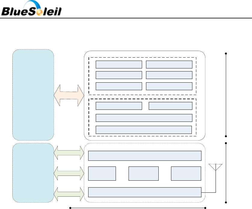
5 Software Stacks
BlueSoleil i410e is supplied with Bluetooth v4.0 compliant stack firmware, which runs on the
internal RISC microcontroller. The i410e software architecture allows Bluetooth processing and
the application program to be shared in different ways between the internal RISC microcontroller
and an external host processor (if any).
BlueSoleil EcoSystem
BlueSoleil EcoSystem
BlueSoleil EcoSystem
BlueSoleil EcoSystem
i410e Datasheet
17 / 28
5.1 BlueSoleil Stack
Radio
Debug
I/O
ARM/MCU/
Any CPU
UART
BlueSoleil
Firmware
Hardware
L2CAP/eL2CAP
SMP ATT/GATT
MCURAM
Link Manager
GPIO
Analogue
AT CMD
Application
i410e Solution
BLP/BLS GLP/GLS
CSCP/CSCS RSCP/RSCS
HID/HOGP HRP/HRS
Figure 4 BlueSoleil Stack
As illustrated in Figure 4 above, no host processor is required to run the Bluetooth protocol
stack. All BlueSoleil stack layers, including application software, run on the internal RISC
processor.
The MCU interfaces to BlueSoleil i410e via one or more of the physical interfaces, which are
also shown in the figure 4. The most common interfacing is done via UART interface using the
ASCII commands supported by the BlueSoleil stack. With these ASCII commands the user can
access Bluetooth functionality without paying any attention to the complexity, which lies in the
Bluetooth protocol stack.
The user may write applications code to run on the MCU to control BlueSoleil stack with
ASCII commands and to develop Bluetooth powered applications. Please refer to
BlueSoleil_i410e_Programming_Manual.pdf.
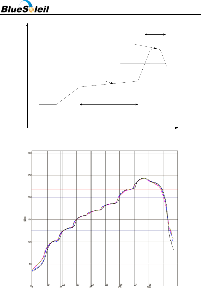
6 Re-flow Temperature-time Profile
The re-flow profiles are illustrated in Figure 5 and Figure 6 below.
BlueSoleil EcoSystem
BlueSoleil EcoSystem
BlueSoleil EcoSystem
BlueSoleil EcoSystem
i410e Datasheet
18 / 28
40+20/-15s
2170C
90+30/-30s
2300C~2450C
1500C~1900C
Temp.(0C)
Time(S)
Figure 5 Typical Lead-Free Re-flow Solder Profile
2170C
2420C
Figure 6 Typical Lead-free Re-flow
The soldering profile depends on various parameters according to the use of different solder
and material. The data here is given only for guidance on solder re-flow.
i410e will withstand up to two re-flows to a maximum temperature of 245°C.
BlueSoleil EcoSystem
BlueSoleil EcoSystem
BlueSoleil EcoSystem
BlueSoleil EcoSystem

i410e Datasheet
19 / 28
7 Reliability and Environmental Specification
7.1 Temperature test
Put the module in demo board which uses exit power supply, power on the module and
connect to mobile. Then put the demo in the ‐40℃ space for 1 hour and then move to +85℃
space within 1minute, after 1 hour move back to ‐40℃ space within1 minute. This is 1 cycle. The
cycles are 32 times and the units have to pass the testing.
7.2 Vibration Test
The module is being tested without package. The displacement requests 1.5mm and sample
is vibrated in three directions(X,Y,Z).Vibration frequency set as 0.5G , a sweep rate of 0.1
octave/min from 5Hz to 100Hz last for 90 minutes each direction. Vibration frequency set as 1.5G,
a sweep rate of 0.25 octave/min from 100Hz to 500Hz last for 20 minutes each direction.
7.3 Desquamation Test
Use clamp to fix the module, measure the pull of the component in the module, make sure
the module`s soldering is good.
7.4 Drop Test
Free fall the module (condition built in a wrapper which can defend ESD) from 150cm height
to cement ground, each side twice, total twelve times. The appearance will not be damaged and
all functions OK.
7.5 Packaging Information
After unpacking, the module should be stored in environment as follows:
- Temperature: 25℃ ± 2℃
- Humidity: <60%
- No acidity, sulfur or chlorine environment
The module must be used in four days after unpacking.
BlueSoleil EcoSystem
BlueSoleil EcoSystem
BlueSoleil EcoSystem
BlueSoleil EcoSystem

i410e Datasheet
20 / 28
8 Layout and Soldering Considerations
8.1 Soldering Recommendations
BlueSoleil i410e is compatible with industrial standard reflow profile for Pb-free solders. The
reflow profile used is dependent on the thermal mass of the entire populated PCB, heat transfer
efficiency of the oven and particular type of solder paste used. Consult the datasheet of
particular solder paste for profile configurations.
IVT Corporation will give following recommendations for soldering the module to ensure
reliable solder joint and operation of the module after soldering. Since the profile used is process
and layout dependent, the optimum profile should be studied case by case. Thus following
recommendation should be taken as a starting point guide.
8.2 Layout Guidelines
It is strongly recommended to use good layout practices to ensure proper operation of the
module. Placing copper or any metal near antenna deteriorates its operation by having effect on
the matching properties. Metal shield around the antenna will prevent the radiation and thus
metal case should not be used with the module. Use grounding via separated max 3 mm apart at
the edge of grounding areas to prevent RF penetrating inside the PCB and causing an
unintentional resonator. Use GND via all around the PCB edges.
The mother board should have no bare conductors or via in this restricted area, because it is
not covered by stop mask print. Also no copper (planes, traces or via) are allowed in this area,
because of mismatching the on-board antenna.
BlueSoleil EcoSystem
BlueSoleil EcoSystem
BlueSoleil EcoSystem
BlueSoleil EcoSystem
i410e Datasheet
21 / 28
Figure 7 i410e Restricted Area
Following recommendations helps to avoid EMC problems arising in the design. Note that
each design is unique and the following list do not consider all basic design rules such as avoiding
capacitive coupling between signal lines. Following list is aimed to avoid EMC problems caused by
RF part of the module. Use good consideration to avoid problems arising from digital signals in
the design.
Ensure that signal lines have return paths as short as possible. For example if a signal goes to
an inner layer through a via, always use ground via around it. Locate them tightly and
symmetrically around the signal via. Routing of any sensitive signals should be done in the inner
layers of the PCB. Sensitive traces should have a ground area above and under the line. If this is
not possible, make sure that the return path is short by other means (for example using a ground
line next to the signal line).
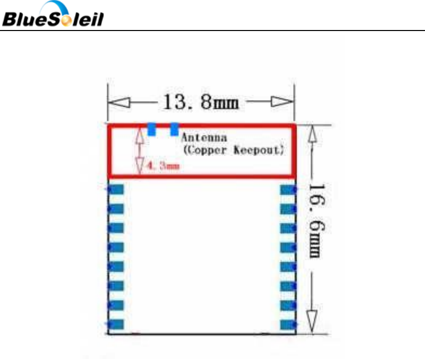
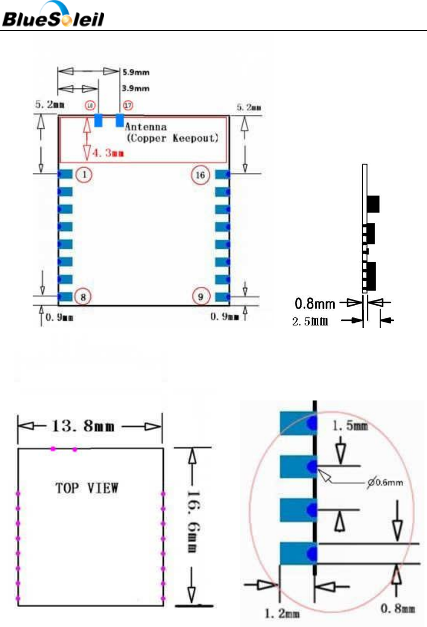
9 Physical Dimensions
BlueSoleil i410e’s dimension is 16.6mm (L) *13.8mm (W)* 2.5mm (H).
BlueSoleil EcoSystem
BlueSoleil EcoSystem
BlueSoleil EcoSystem
BlueSoleil EcoSystem
i410e Datasheet
22 / 28
Figure 8 i410e Footprint
BlueSoleil EcoSystem
BlueSoleil EcoSystem
BlueSoleil EcoSystem
BlueSoleil EcoSystem
i410e Datasheet
23 / 28
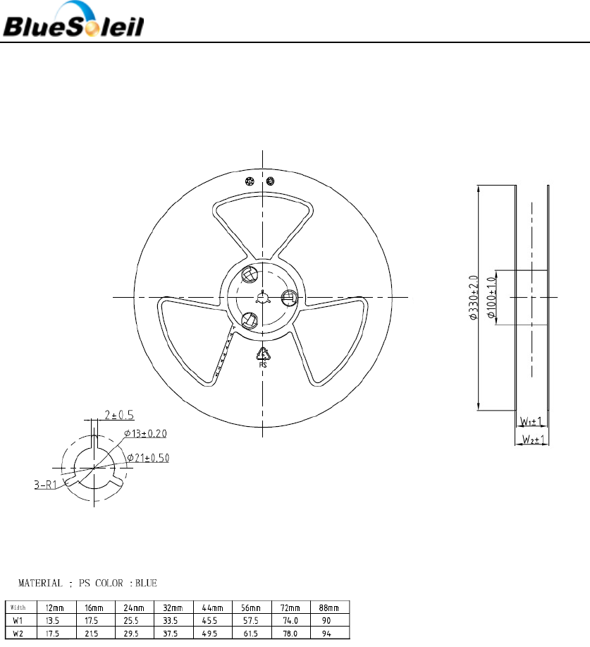
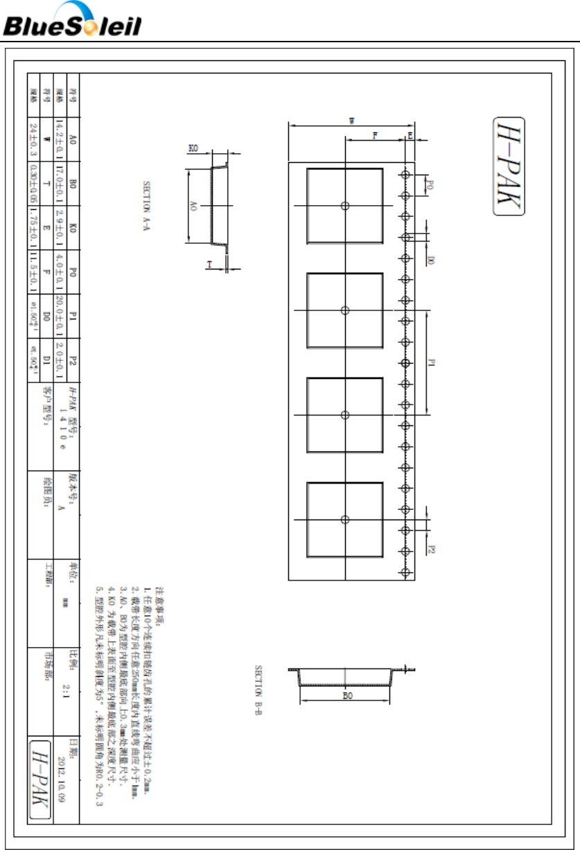
10 Package
Figure 9 Reel Information
BlueSoleil EcoSystem
BlueSoleil EcoSystem
BlueSoleil EcoSystem
BlueSoleil EcoSystem
i410e Datasheet
24 / 28
Figure 10 Tape Information
BlueSoleil EcoSystem
BlueSoleil EcoSystem
BlueSoleil EcoSystem
BlueSoleil EcoSystem
i410e Datasheet
25 / 28
11 Certification
11.1 Bluetooth
BlueSoleil i410e module is qualified as a Bluetooth controller subsystem and it fulfills all the
mandatory requirements of Bluetooth 4.0 core specification. If not modified in any way, it is a
complete Bluetooth entity, containing software and hardware functionality as well as the whole
RF-part including the antenna. This practically translates to that if the module is used without
modification of any kind, it does not need any Bluetooth approval work for evaluation on what
needs to be tested.
i410e Qualified Design ID (QDID): B020729
11.2 CE 0700
Hereby, IVT Corporation declares that this device is in compliance with the essential
requirements and other relevant provisions of Directive 1999/5/EC.
11.3 FCC
Host manufacturer: IVT Corporation
Host Brand name: BlueSoleil
Host model number: i410e
FCC ID: S78-IVTI410E
11.4 IC
Host manufacturer: IVT Corporation
Host Brand name: BlueSoleil
Host model number: i410e
IC: 11004A-IVTI410E
The output power of this device is less than 20mW. The SAR test is not required. When using
it, ensure that the antenna of the device is at least 20cm away from all persons.
BlueSoleil EcoSystem
BlueSoleil EcoSystem
BlueSoleil EcoSystem
BlueSoleil EcoSystem

i410e Datasheet
26 / 28
This device complies with Industry Canada licence-exempt RSS standard(s). Operation is
subject to the following two conditions: (1) this device may not cause interference, and (2) this
device must accept any interference, including interference that may cause undesired operation
of the device.
This device complies with Part 15 of the FCC Rules and with RSS-210 of Industry Canada.
Operation is subject to the following two conditions: (1) This device may not cause harmful
interference, and (2) this device must accept any interference received, including interference
that may cause undesired operation.
Le présent appareil est conforme aux CNR d'Industrie Canada applicables aux appareils radio
exempts de licence.
L'exploitation est autorisée aux deux conditions suivantes : (1) l'appareil ne doit pas produire
de brouillage, et (2) l'utilisateur de l'appareil doit accepter tout brouillage radioélectrique subi,
même si le brouillage est susceptible d'en compromettre le fonctionnement.
This Class B digital apparatus complies with Canadian ICES-003.
Cet appareil numérique de la classe B est conforme à la norme NMB-003 du Canada.
NOTE: The manufacturer is not responsible for any radio or TV interference caused by
unauthorized modifications or changes to this equipment. Such modifications or changes could
void the user’s authority to operate the equipment.
NOTE: This equipment has been tested and found to comply with the limits for a Class B
digital device, pursuant to part 15 of the FCC Rules. These limits are designed to provide
reasonable protection against harmful interference in a residential installation. This equipment
generates uses and can radiate radio frequency energy and, if not installed and used in
accordance with the instructions, may cause harmful interference to radio communications.
However, there is no guarantee that interference will not occur in a particular installation. If this
equipment does cause harmful interference to radio or television reception, which can be
determined by turning the equipment off and on, the user is encouraged to try to correct the
interference by one or more of the following measures:
- Reorient or relocate the receiving antenna.
- Increase the separation between the equipment and receiver.
-Connect the equipment into an outlet on a circuit different from that to which the receiver
is connected.
-Consult the dealer or an experienced radio/TV technician for help.
BlueSoleil EcoSystem
BlueSoleil EcoSystem
BlueSoleil EcoSystem
BlueSoleil EcoSystem

i410e Datasheet
27 / 28
12 Bluetooth Technology Best Developed
Corporation
IVT Corporation is one of Bluetooth technology BEST developed together which is
authenticated by The Bluetooth SIG. See Figure 11 below.
Figure 11 IVT is one of Bluetooth technology BEST developed together
13 Contact Information
Contacts: Mr. Zhu Yong
Mobile: +86 18910255873
Tel: +86 10 82898219
Fax: +86 10 62963059
Email: embedded@ivtcorporation.com
Address: IVT Corporation 5/F, Fa Zhan Building No.12, Shang Di Xin Xi Road, Beijing, 100085 P.R.
China
Company Site: www.ivtcorporation.com
Support: support@ivtcorporation.com
BlueSoleil EcoSystem
BlueSoleil EcoSystem
BlueSoleil EcoSystem
BlueSoleil EcoSystem

i410e Datasheet
28 / 28
14 Copyright
Copyright © 1999-2013 IVT Corporation
All rights reserved.
IVT Corporation assumes no responsibility for any errors which may appear in the specification.
Furthermore, IVT Corporation reserves the right to alter the hardware, software, and/or
specification detailed here at any time without notice and does not make any commitment to
update the information contained here.
BlueSoleil is a registered trademark of IVT Corporation for Bluetooth production.
The Bluetooth trademark is owned by The Bluetooth SIG Inc., USA and is licensed to IVT
Corporation.
All other trademarks listed herein are owned by their respective owners.
BlueSoleil EcoSystem
BlueSoleil EcoSystem
BlueSoleil EcoSystem
BlueSoleil EcoSystem