Barrot Technology IVTI50E Bluetooth Module User Manual
IVT Corporation Bluetooth Module
UserManual.wiki
>
Barrot Technology
>
IVTI50E User Manual
User Manual
Navigation menu
Upload a User Manual
Namespaces
Wiki Guide
HTML
PDF
Info
Views
User Manual
Discussion / Help
Navigation
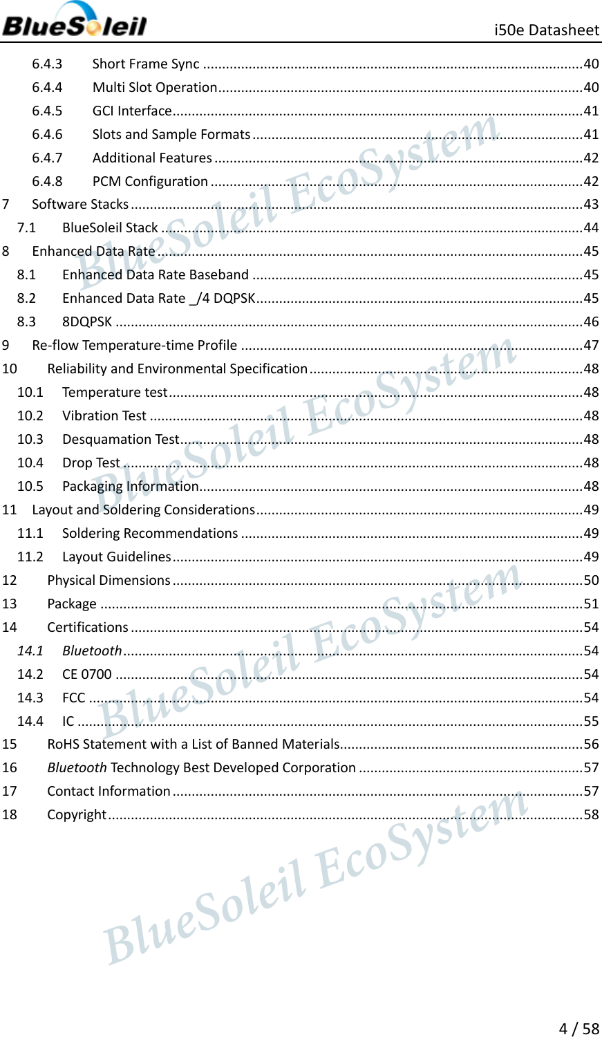
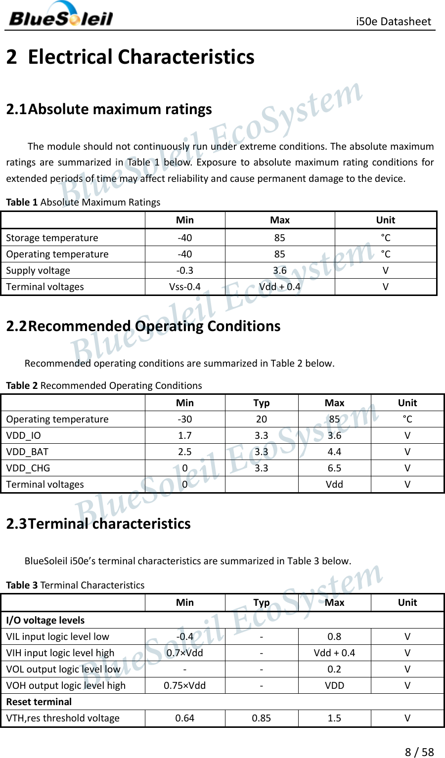
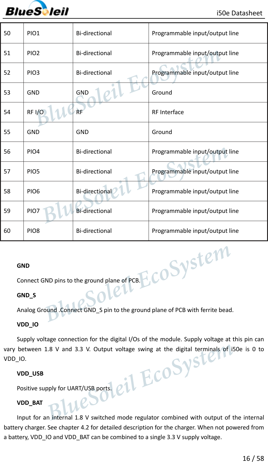
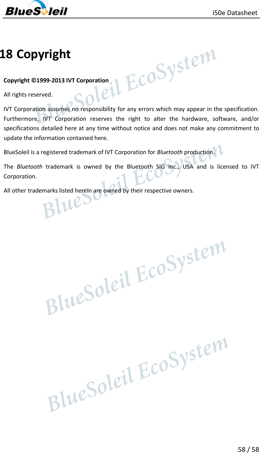
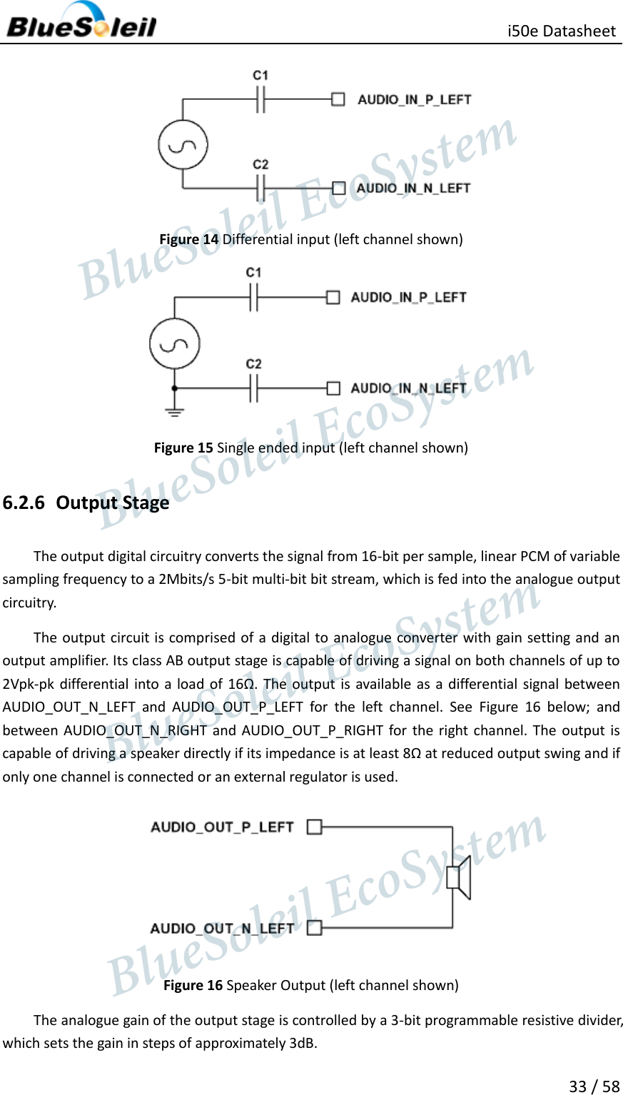
![ i50e Datasheet 23 / 58 Equation 2 Baud Rate Calculation Formula Table 11 UART Baud Rates and Error Values Baud Rate Persistent store values Error Hex Dec 1200 0x0005 5 1.73% 2400 0x000a 10 1.73% 4800 0x0014 20 1.73% 9600 0x0027 39 -0.82% 19200 0x004f 79 0.45% 38400 0x009d 157 -0.18% 57600 0x00ec 263 0.03% 76800 0x013b 315 0.14% 115200 0x01d8 472 0.03% 230400 0x03b0 944 0.03% 460800 0x075f 1887 -0.02% 921600 0x0ebf 3775 0.00% 1382400 0x161e 5662 -0.01% 1843200 0x1d7e 7550 0.00% 2765800 0x2c3d 11325 0.00% 5.1.1 UART Configuration While RESET is Active The UART interface for i50e while the chip is being held in reset is tri-state. This will allow the user to daisy chain devices onto the physical UART bus. The constraint on this method is that any devices connected to this bus must tri-state when i50e reset is de-asserted and the firmware begins to run. 5.1.2 UART Bypass Mode Alternatively, for devices that do not tri-state the UART bus, the UART bypass mode on i50e can be used. The default state of i50e after reset is de-asserted, this is for the host UART bus to be connected to the i50e UART, thereby allowing communication to i50e via the UART. In order to apply the UART bypass mode, a BCCMD command will be issued to i50e upon this, it will switch the bypass to PIO[7:4] as shown in Figure 7. Once the bypass mode has been invoked, i50e will enter the deep sleep state indefinitely. BlueSoleil EcoSystem BlueSoleil EcoSystem BlueSoleil EcoSystemBlueSoleil EcoSystem](https://usermanual.wiki/Barrot-Technology/IVTI50E/User-Guide-2010556-Page-23.png)
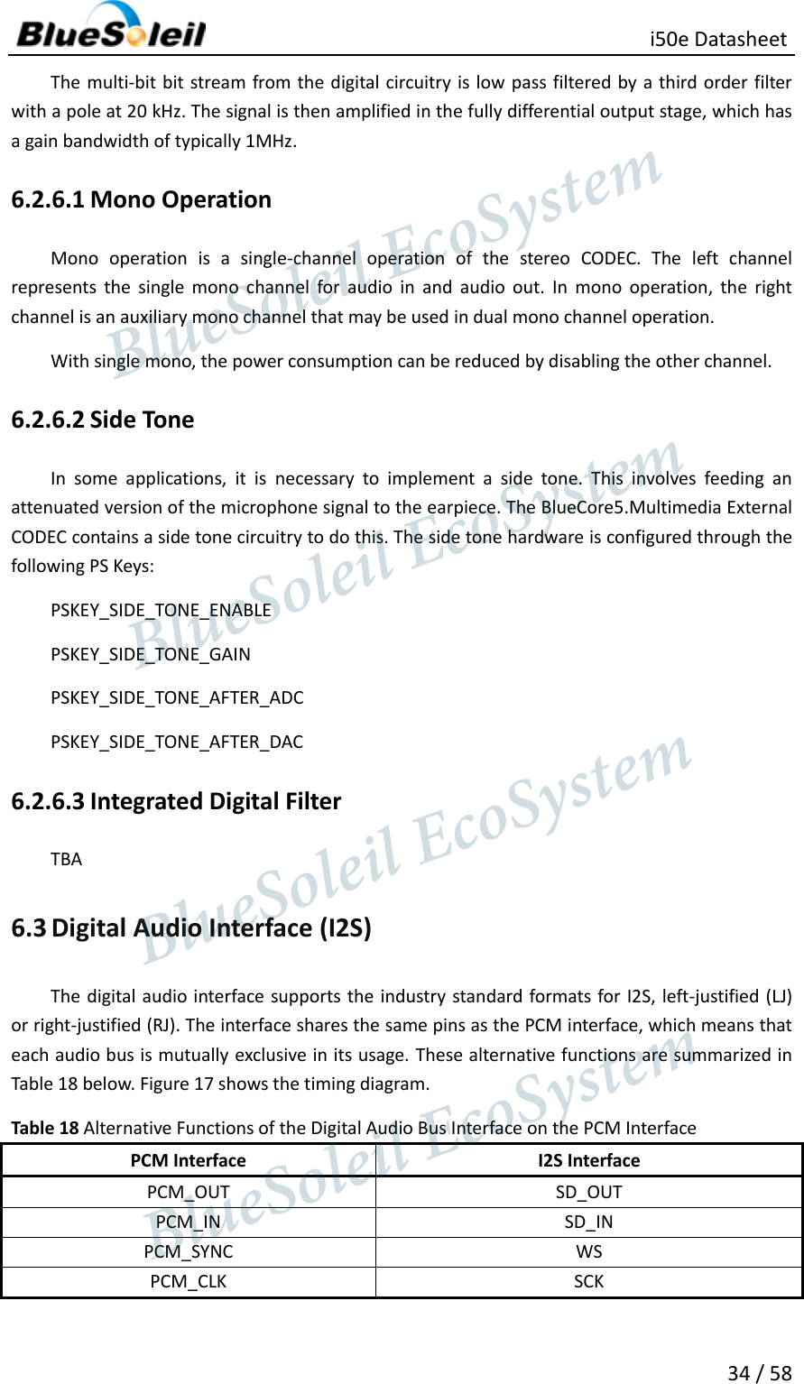
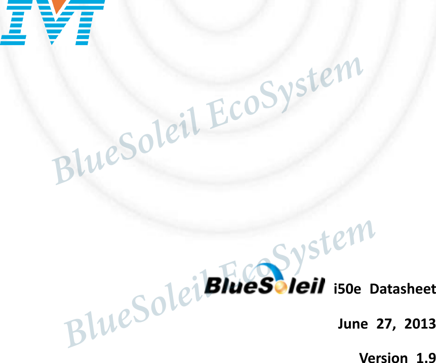
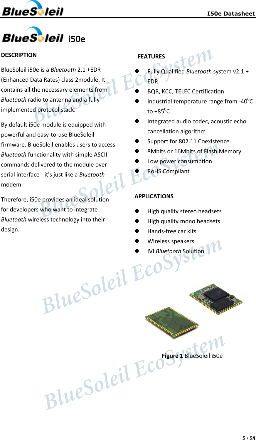
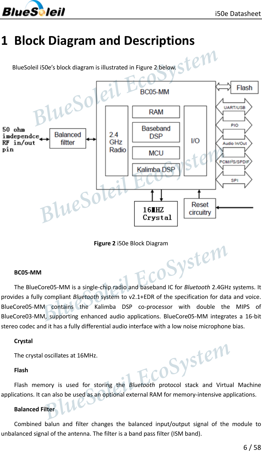
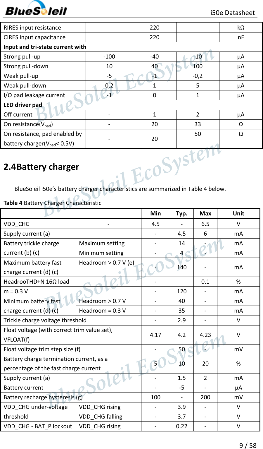
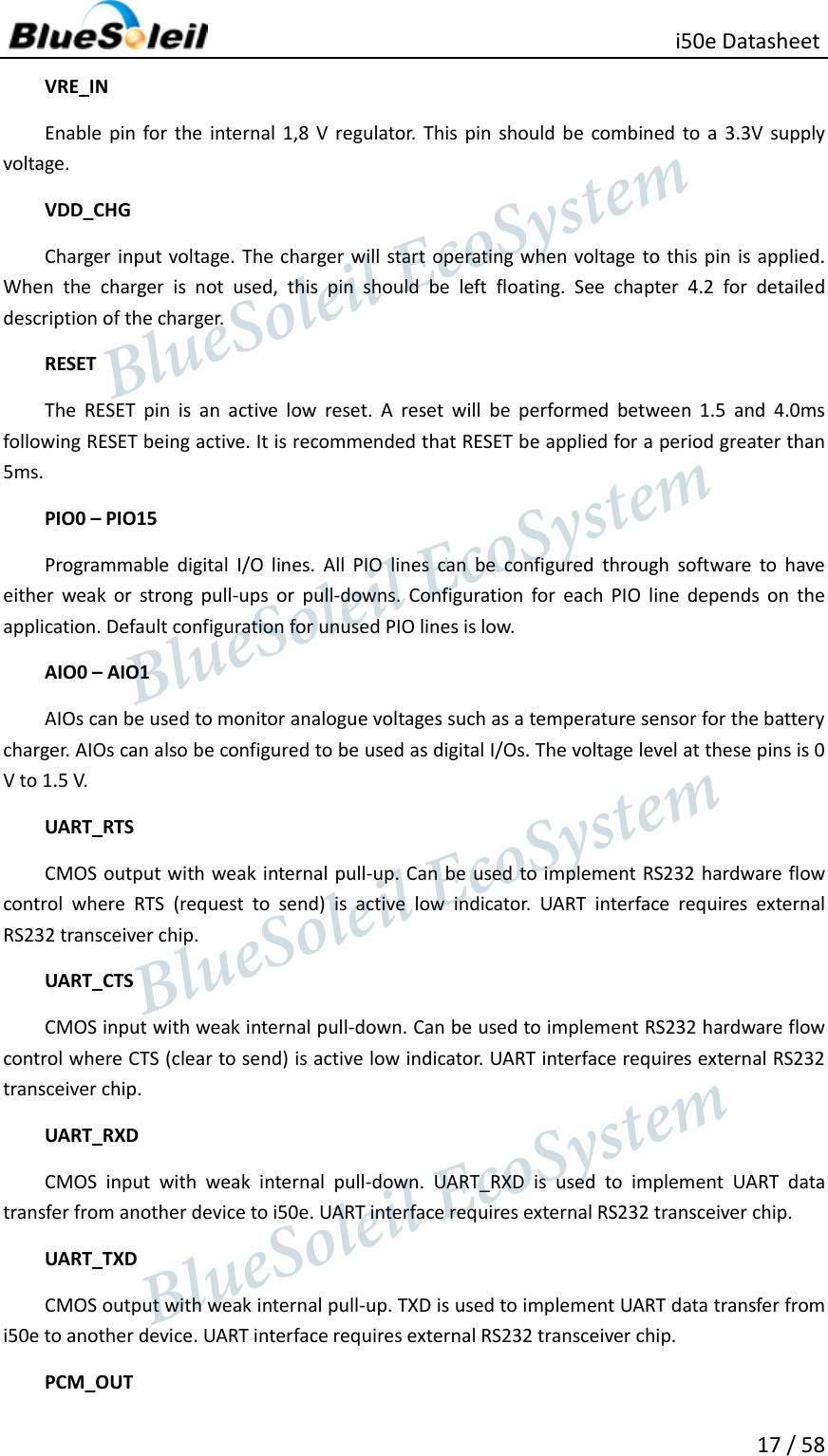
![ i50e Datasheet 35 / 58 Figure 17 Digital Audio Interface Modes Table 19 below introduces the values for the PS Key (PSKEY_DIGITAL_AUDIO_CONFIG) that is used to set-up the digital audio interface. For example, to configure an I2S interface with 16-bit SD data set PSKEY_DIGITAL_CONFIG to 0x0406. Table 19 PSKEY_DIGITAL_AUDIO_CONFIG Bit Mask Name Description D[0] 0x0001 CONFIG_JUSTIFY_FORMAT 0 for left justified, 1 for right justified. D[1] 0x0002 CONFIG_LEFT_JUSTIFY_DELAY For left justified formats: 0 is MSB of SD data occurs in the first SCLK period following WS transition. 1 is MSB of SD data occurs in the second SCLK period. D[2] 0x0004 CONFIG_CHANNEL_POLARITY For 0, SD data is left channel when WS is high. For 1 SD data is right channel. D[3] 0x0008 CONFIG_AUDIO_ATTEN_EN For 0, 17 bit SD data is rounded down to 16 bits. For 1, the audio attenuation defined BlueSoleil EcoSystem BlueSoleil EcoSystem BlueSoleil EcoSystemBlueSoleil EcoSystem](https://usermanual.wiki/Barrot-Technology/IVTI50E/User-Guide-2010556-Page-35.png)
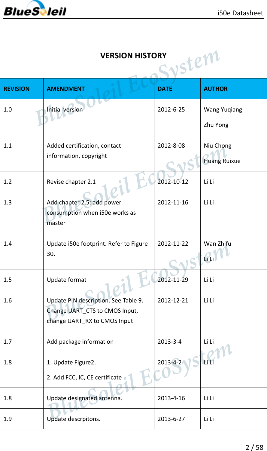
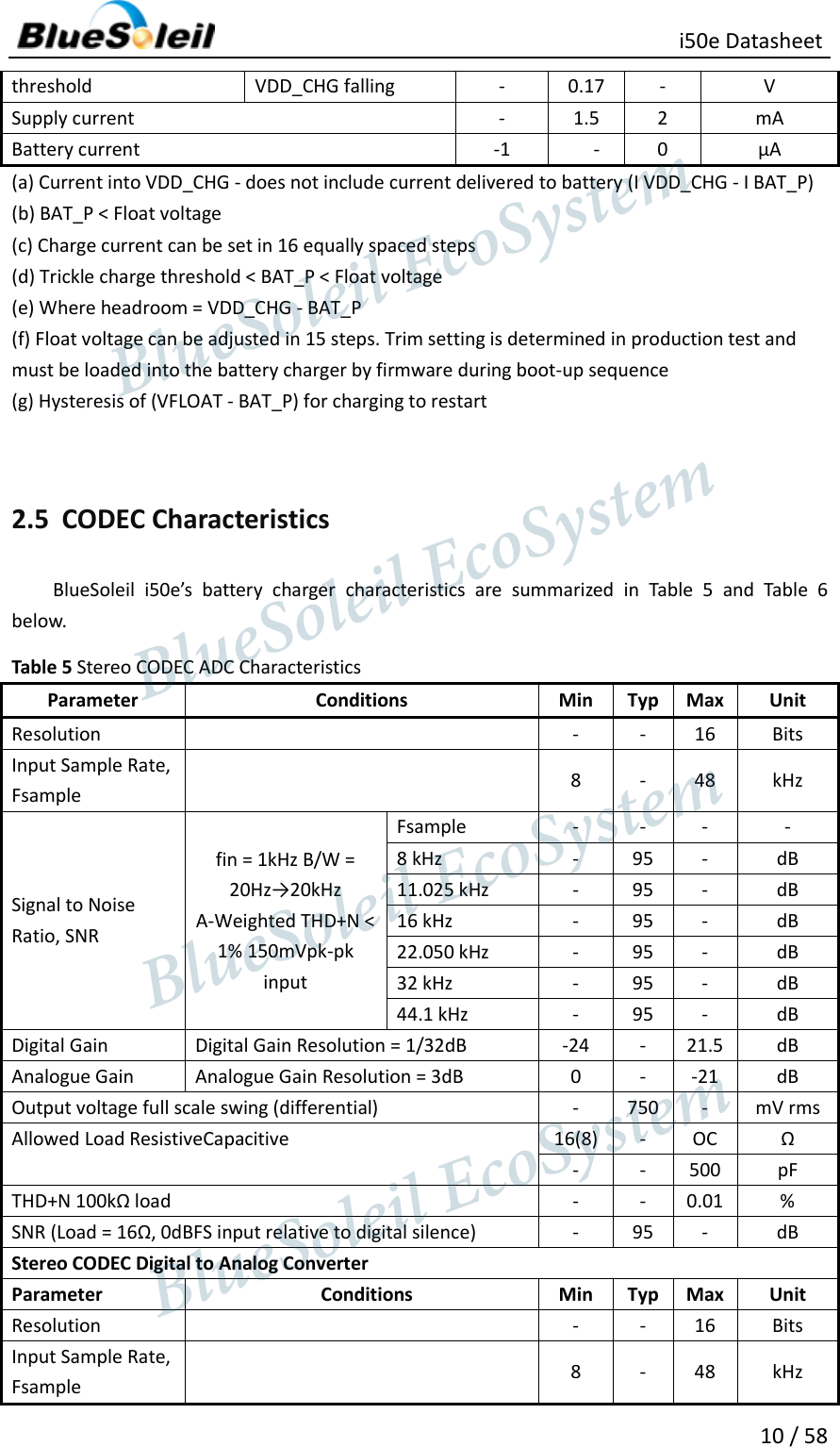
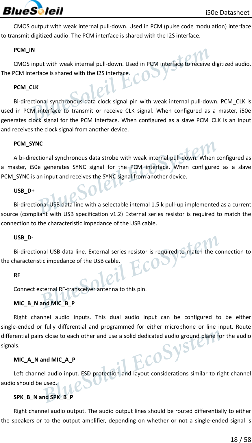
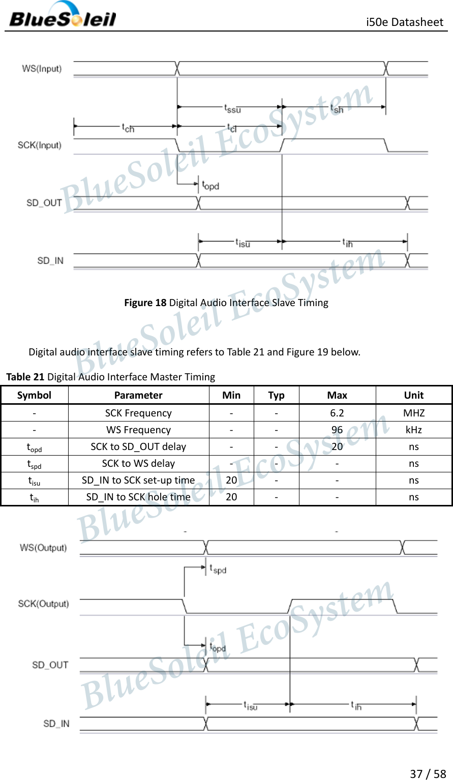
![ i50e Datasheet 36 / 58 in CONFIG_AUDIO_ATTEN is applied over 24 bits with saturated rounding. Requires CONFIG_16_BIT_CROP_EN to be 0. D[7:4] 0x00F0 CONFIG_AUDIO_ATTE Attenuation in 6 dB steps. D[9:8] 0x0300 CONFIG_JUSTIFY_RESOLUTION Resolution of data on SD_IN, 00=16 bit, 01=20 bit, 10=24 bit, 11=Reserved. This is required for right justified format and with left justified LSB first. D[10] 0x0400 CONFIG_16_BIT_CROP_EN For 0, 17 bit SD_IN data is rounded down to 16 bits. For 1 only the most significant 16 bits of data are received. The internal representation of audio samples withinBlueCore5.Multimedia External is 16-bit and data on SD_OUT is limited to 16-bit per channel. Digital audio interface slave timing refers to Table 20 and Figure 18 below. Table 20 Digital Audio Interface Slave Timing Symbol Parameter Min Typ Max Unit - SCK Frequency - - 6.2 MHZ - WS Frequency - - 96 kHz tch SCK high time 80 - - ns tcl SCK low time 80 - - ns topd SCK to SD_OUT delay - - 20 ns tssu WS to SCK set-up time 20 - - ns tsh WS to SCK hold time 20 - -- ns tisu SD_IN to SCK set-up time 20 - - ns tih SD_IN to SCK hole time 20 - - ns BlueSoleil EcoSystem BlueSoleil EcoSystem BlueSoleil EcoSystemBlueSoleil EcoSystem](https://usermanual.wiki/Barrot-Technology/IVTI50E/User-Guide-2010556-Page-36.png)
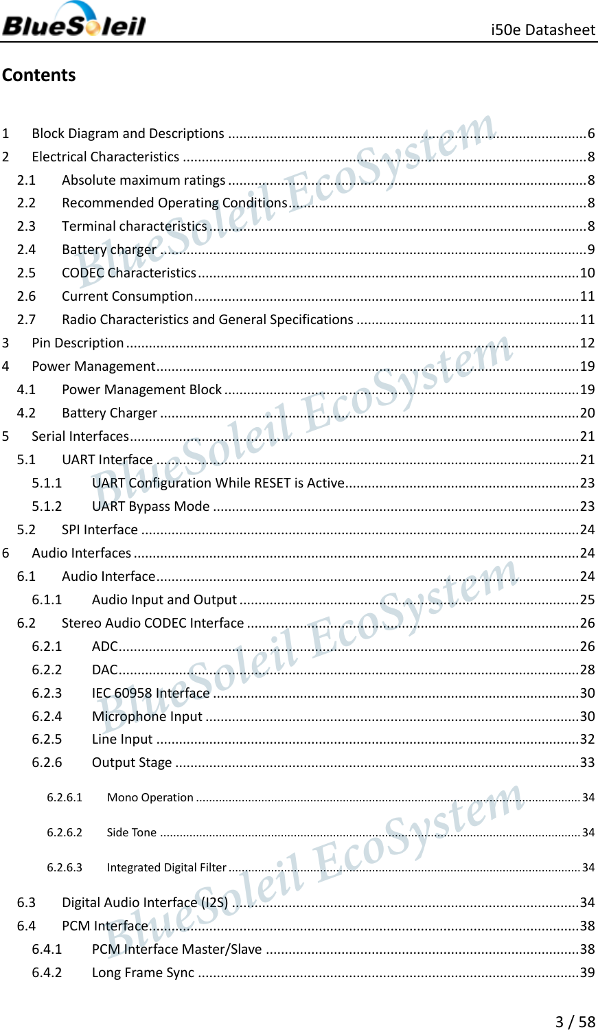
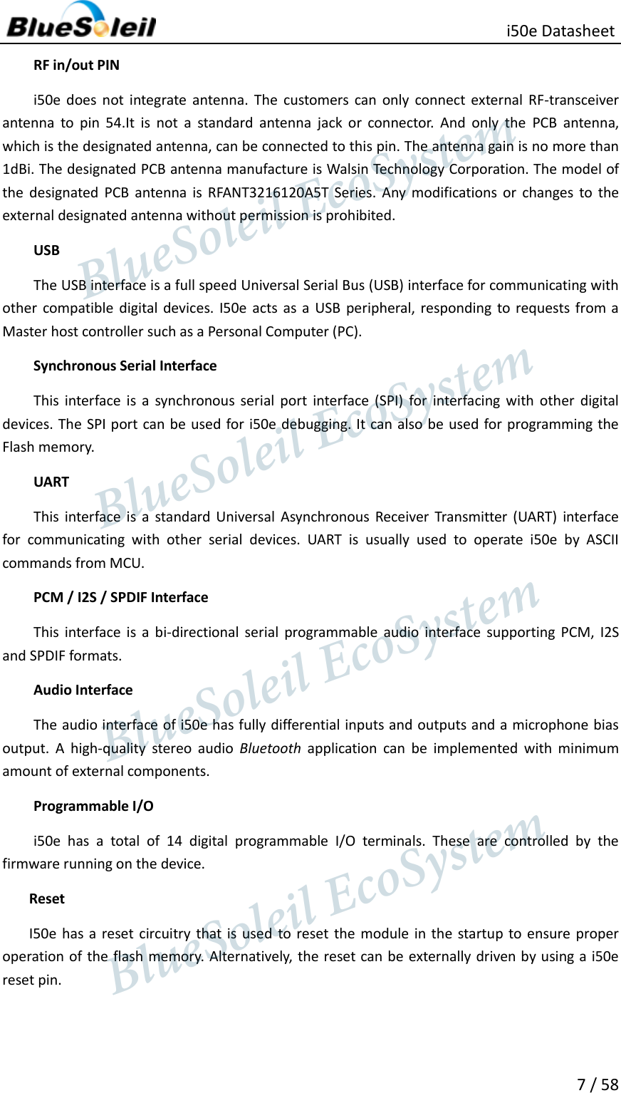
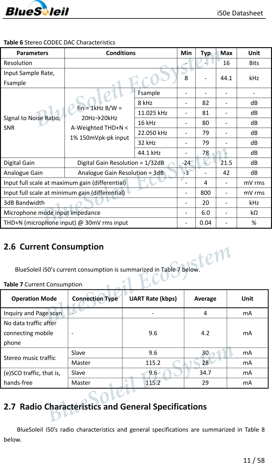
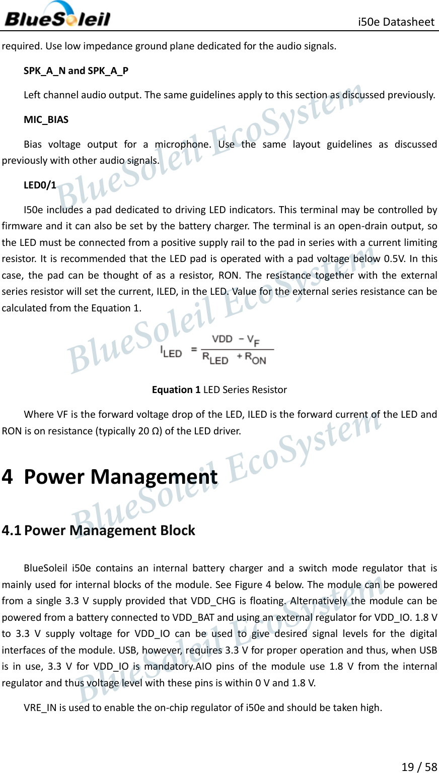
![ i50e Datasheet 43 / 58 TX TRISTATE EN 6 0 drives PCM_OUT continuously, 1 tri-states PCM_OUT immediately after the falling edge of PCM_CLK in the last bit of an active slot, assuming the next slot is not active. TX TRISTATE RISING EDGE EN 7 0 tristates PCM_OUT immediately after the falling edge of PCM_CLK in the last bit of an active slot, assuming the next slot is also not active. 1 tristates PCM_OUT after the rising edge of PCM_CLK. SYNC SUPPRESS EN 8 0 enables PCM_SYNC output when master, 1 suppresses PCM_SYNC whilst keeping PCM_CLK running. Some CODECS utilize this to enter a low power state. GCI MODE EN 9 1 enables GCI mode. MUTE EN 10 1 forces PCM_OUT to 0. 48M PCM CLK GEN EN 11 0 sets PCM_CLK and PCM_SYNC generation via DDS from internal 4 MHz clock, as for BlueCore4-External. 1 sets PCM_CLK and PCM_SYNC generation via DDS from internal 48 MHz clock. LONG LENGTH SYNC EN 12 0 sets PCM_SYNC length to 8 PCM_CLK cycles and 1 sets length to 16 PCM_CLK cycles. Only applies for long frame sync and with 48M_PCM_CLK_GEN_EN set to 1. - [20:16] Set to 0b00000. MASTER CLK RATE [22:21] Selects 128 (0b01), 256 (0b00), 512 (0b10) kHz PCM_CLK frequency when master and 48M_PCM_CLK_GEN_EN (bit 11) is low. ACTIVE SLOT [26:23] Default is 0001. Ignored by firmware SAMPLE_FORMAT [28:27] Selects between 13 (0b00), 16 (0b01), 8 (0b10) bit sample with 16 cycle slot duration 8 (0b11) bit sample 8 cycle slot duration. Table 23 PSKEY_PCM_LOW_JITTER_CONFIG Name Bit position Description CNT LIMIT [12:0] Sets PCM_CLK counter limit CNT RATE [23:16] Sets PCM_CLK count rate. SYNC LIMIT [31:24] Sets PCM_SYNC division relative to PCM_CLK. 7 Software Stacks i50e is supplied with Bluetooth v2.1 + EDR compliant stack firmware, which runs on the internal RISC microcontroller. The i50e software architecture allows Bluetooth processing and the BlueSoleil EcoSystem BlueSoleil EcoSystem BlueSoleil EcoSystemBlueSoleil EcoSystem](https://usermanual.wiki/Barrot-Technology/IVTI50E/User-Guide-2010556-Page-43.png)