Baumer Electric OIS-W-WR300303 RF-Identification System User Manual Interface
Baumer Electric AG RF-Identification System Interface
Contents
- 1. Installation
- 2. Interface
- 3. Maintenance
Interface

Application Not
e
OIS-W Interface Specification
2000 Baumer Ident AG Switzerland
OIS-W Reader Communication Interface
PROJECT
PROJECT: COMMUNICATION
INTERFACE
AUTHOR: W. STEHLING
ATTN: SYSTEM INTEGRATORS
CC:
DOCUMENT
CREATED: 08. DECEMBER
1999
LAST
CHANGE: 27. SEPTEMBER 2000
VERSION: VERSION 1.1
FILE: SPWR-2101-0001.DOC

Baumer Ident AG OIS-W Interface Specificatio
n
date: 20.02.2001
author: wst file: Interface.doc
version 1.0 page: 2 / 2
Content
History
Related documents
About the document
Disclaimer
1 Introduction 4
2 Hardware requirements 4
3 Reader operating modes 5
3.1 Automatic Data Transmission 5
3.2 Communication upon request 6
3.3 Code lookup table 7
4 rotocol overview 8
4.1 General message structure 8
4.2 Data coding and byte order 9
5 Communication messages 10
5.1 Automatically transmitted messages 10
5.1.1 TAG_ID_IND: Send code information 10
5.1.2 PARAM_DATA_REP: Send extended code information 11
5.1.3 RESET_IND: Reset indication of reader 12
5.2 Request Information from reader 12
5.2.1 VERSION_REQ: Get software version information from reader 12
5.3 Information transmitted to the reader 13
5.3.1 DOWNLOAD_REQ: Download lookup table to reader 13
5.4 Auxiliary Port Information and Settings 15
Appendix A: CRC calculation 16
Appendix B: OIS-W messages 17
1 Automatically transmitted messages ......................................................................................17
2 Request information from the reader ......................................................................................17
3 Information transmitted to the reader......................................................................................19
Appendix C: C/C++ header definitions 20
1 Global Definitions ....................................................................................................................20
2 Size definition of variables.......................................................................................................21
3 Structure definitions ................................................................................................................21
4 Definition of message numbers ..............................................................................................23
5 Error numbers .........................................................................................................................24

Baumer Ident AG OIS-W Interface Specificatio
n
date: 20.02.2001
author: wst file: Interface.doc
version 1.0 page: 3 / 3
History
1.0 99/12/08 first draft wst
1.1 00/09/27 modification on AUX_REP message and auxiliary heg
Related documents
[1]: Kühn, I., STAR2 SW Interface Specification, V 1.05 (1999/11/03), Elektrobit AG
[2]: Zehnder, C., OIS-W User's Manual, V 3.0E (1999/09/28), Baumer Ident AG, MSGY-2001-305
About the document
This application note describes the communication protocol of the OIS-W reader unit. It is intended for
system integrators who need to set up the host's part of the communication. The protocol used with the
serial interfaces will be explained in detail.
Disclaimer
The information contained in this document is believed to be accurate and reliable. It is based on the pro-
tocol stack version 2.28. However, no responsibility is assumed by Baumer Ident for its use, nor for any
infringements of patents or other rights of third parties which may result from its use. No license is
granted by implication or otherwise under any patent or patent rights of Baumer Ident.
© Baumer Ident AG, 2000
Baumer Ident AG OIS-W Interface Specificatio
n
date: 20.02.2001
author: wst file: Interface.doc
version 1.0 page: 4 / 4
1 Introduction
The OIS-W reader is fully programmable, i.e. there are no switches or jumpers to set, everything can be
configured by software. Configuration parameters as well as the operating system itself may be
downloaded in the field. A host computer may be connected to each of the two serial interfaces of the ba-
sic reader unit.
The main application of the serial interfaces is to transmit status information to a host computer. If the
reader detects a valid code ID the information may be sent automatically or on request. The reader can be
configured to run continuously or to start a measurement triggered by a switch or by computer.
The protocol used to communicate with the reader is similar to the popular Siemens 3964R protocol. It
will be described in subsequent chapters.
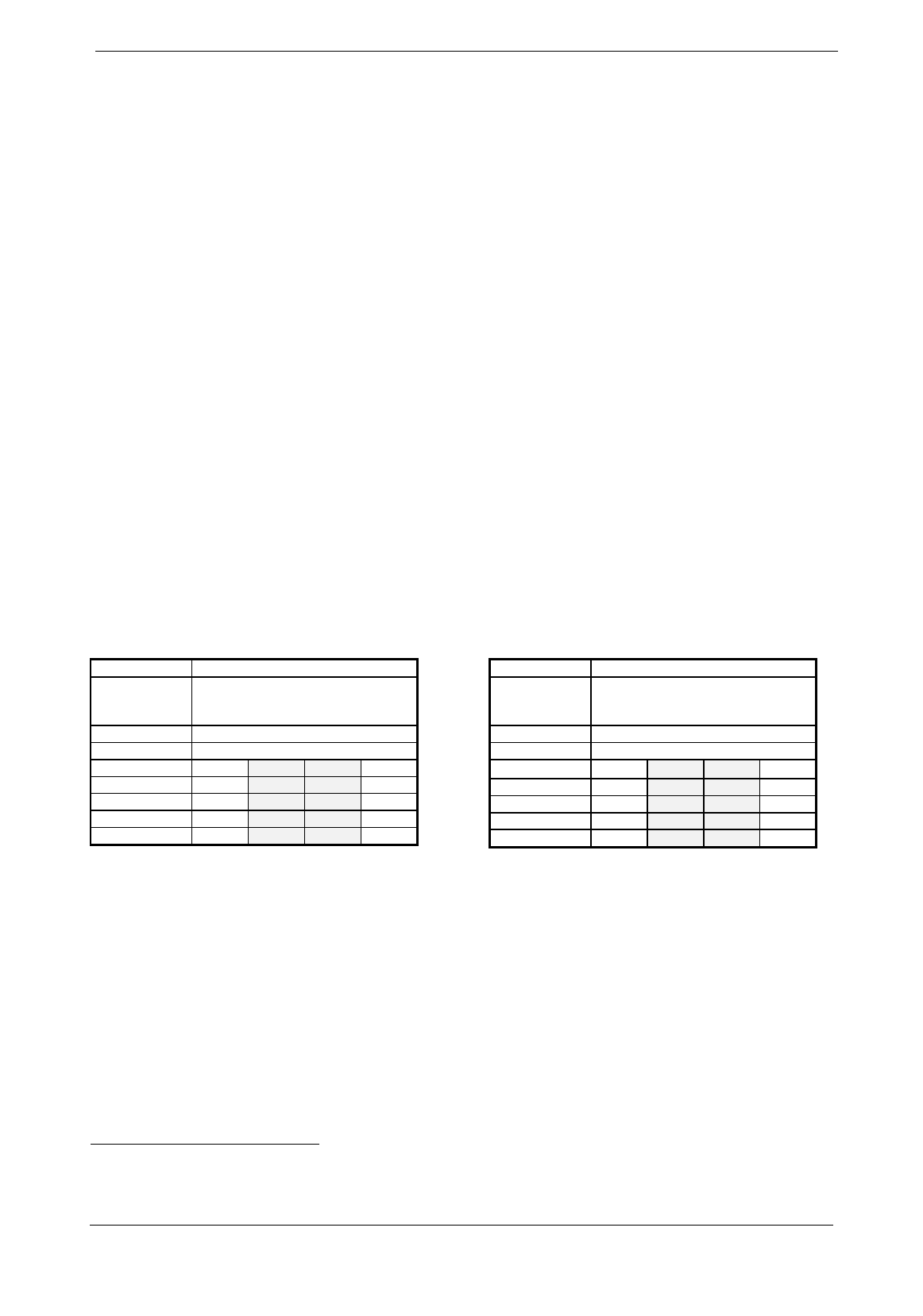
2 Hardware requirements
The two serial interfaces of the reader are functional identical. Each may be used to connect to a host.
They differ in the physical signal levels only: the upper one corresponds electrically to RS 232, the lower
one to RS 422 levels (Table 2-1 and Table 2-2, respectively).
1 Only RxD and TxD are currently supported.
2 Internally connected to GND via 195 Ω.
Signal Level RS232
Baud rates
default 9600 baud
optional 115'200 baud
Parameter 8 bit, 1stop bit, no parity
Connector 9-Pin D-Sub, male (DTE)
Pin Assignment 1 DCD
DSR 6 2 RxD
RTS 7 3 TxD
CTS 8 4 DTR
RI 9 5 GND
Table 2-1: RS 232 serial interface of the basic OIS-W reader unit1
Signal level: RS422
Baud rates:
default 9600 baud
optional 115'200 baud
Parameter 8 bit, 1stop bit, no parity
Plug 9-Pin D-Sub, female (DTE)
Pin assignment 5 GND2
RxD- 9 4
RxD+ 8 3
TxD+ 7 2
TxD- 6 1 GND2
Table 2-2: RS 422 serial interface of the basic OIS-W reader unit

Baumer Ident AG OIS-W Interface Specificatio
n
date: 20.02.2001
author: wst file: Interface.doc
version 1.0 page: 5 / 5
3 Reader operating modes
Basically, the reader may operate in one of two main modes: triggered or free running. In triggered mode
a new measurement starts as soon as an external signal is supplied or a trigger message from the host is
received. In free running mode the reader is looking continuously for a valid identification.
An identification message (or an appropriate error message in triggered mode) can be sent to a host in
two ways: automatically or on request by the host. Usually, the automatic ID data message is sufficient in
most applications.
The functionality of the reader is controlled by a configuration file that allows setting of all parameters.
Figure 3-1 shows the part of the configuration file dealing with the communication. The other parts of the
file are not subject of this documentation. For further details see [2].
// BAUMER IDENT SAW tag reader STAR2
// configuration data
// date: 09.06.1999
// time: 10:03:45
// settings serial interface
Bdrate RS422 1152 Baud rate RS422 IF [ 12.. 1152]
Bdrate RS232 1152 Baud rate RS232 IF [ 12.. 1152]
Msg Type ID 11 select type of notification after successful reading [ 0.. 19]
TidF 2 s time const ID filter (res:.5s) [0.5..32767]
ID Msg Retry 2 max. number transmissions of ID Msg(0=no maximum) [ 0.. 255]
ID Msg Timeout 2 s time until ID msg is retransmitted (res:0.5s, 0=no limit) [ 0..127.5]
// settings auxiliary ports
:
:
:
:
Aux over RS 422 0 choose RS422 interface for Aux State Indication message (0 = OFF; 1 = ON)
[ 0.. 1]
Aux over RS 232 0 choose RS232 interface for Aux State Indication message (0 = OFF; 1 = ON)
[ 0.. 1]
Aux IN 1 Rep 1 Aux State Indication mask (0 = OFF; 1 = ON) [ 0.. 1]
Aux IN 2 Rep 1 Aux State Indication mask (0 = OFF; 1 = ON) [ 0.. 1]
Aux OUT 1 Rep 1 Aux State Indication mask (0 = OFF; 1 = ON) [ 0.. 1]
Aux OUT 2 Rep 1 Aux State Indication mask (0 = OFF; 1 = ON) [ 0.. 1]
Figure 3-1: The section of the reader configuration file dealing with communication
3.1 Automatic Data Transmission
Several parameters of the configuration file describe the automatic messaging (Figure 3-1):
• The MsgTypeID entry of the configuration file defines the way how and where an automatic ID
message will be sent. The first digit designates the interface (0: RS 422, 1: RS 232), the second digit
indicates the message type (0: no message, 1: TAG_ID_IND, 2: PARAM_DATA). The message details
will be explained below.
• TidF is a filter time constant. The same message is sent again after this time has elapsed, if the same
ID code is detected repeatedly.
• IDMsgRetry gives the number of repetitions the message will be transmitted, if the host does not
acknowledge the telegram. The parameter is set to 0, if an acknowledge is mandatory; it is set to 1, if
an acknowledge might be missing.
• IDMsgTimeout is the time to wait for acknowledge between the repetitions.

Baumer Ident AG OIS-W Interface Specificatio
n
date: 20.02.2001
author: wst file: Interface.doc
version 1.0 page: 6 / 6
Note: The host can define the readout rate by delaying the acknowledge of the previous
message appropriately.
• Aux over RS 422 if the value is set to ”1” the reader sends its AUX_REP message to the RS 422
interface
• Aux over RS 232 if the value is set to ”1” the reader sends its AUX_REP message to the RS 232
interface
• Aux IN 1 Rep represents the digital input from antenna 1. If the value is set to ”1” the reader
sends its AUX_REP message if a change of state on this pin is detected, the flag for this pin is set if
any change since the former message is detected
• Aux IN 2 Rep represents the digital input from antenna 2. If the value is set to ”1” the reader
sends its AUX_REP message if a change of state on this pin is detected, the flag for this pin is set if
any change since the former message is detected
• Aux OUT 1 Rep represents the digital output from antenna 1. If the value is set to ”1” the reader
sends its AUX_REP message if a change of state on this pin is detected, the flag for this pin is set if
any change since the former message is detected
• Aux OUT 2 Rep represents the digital output from antenna 2. If the value is set to ”1” the reader
sends its AUX_REP message if a change of state on this pin is detected, the flag for this pin is set if
any change since the former message is detected
Note: If no interface is set, no AUX_REP message is sent, until the host sends an AUX_REQ
message. The further parameters have no effect in case of inactive serial interfaces.
For further information see table 5-12.
There are four messages that can be transmitted automatically by the reader. The first one is the reset in-
dicator (RESET_IND), which is sent through both interfaces simultaneously. The host's software must be
aware that a reset message may arrive any time to indicate that the reader has been initialized.
The next two messages are TAG_ID_IND and PARAM_DATA_REP. One of them (not both) may be sent
to any serial interface (not both) as described by MsgTypeID (see above). While TAG_ID_IND sends
the ID code information only, PARAM_DATA_REP gives additional information about the measurement.
Both messages may also be requested by the host (TAG_ID_REQ and DATA_REQ respectively).
The last message to be transmitted automatically, is the AUX_REP. Conditions for sending the informa-
tion without request by the host, are as follows.
The parameters Aux over RS422 and / or Aux over RS232 are set. Further, minimum one of the
Aux…Rep must be set. Now a message will be sent by the reader, if one of the desired auxiliary ports
changes. In case of setting both interfaces, the message is send on each simultaneously. If no desired Aux
State is set (all port parameters to zero and any interface set to “1”) a message won’t be sent in no case. If
AUX_REP is sent, you get information of all actual auxiliary port states. You get also information about
which state did change since the last message was sent.
3.2 Communication upon request
All other messages are generally initiated by the host. They can be grouped into request messages (for in-
stance status of the reader) or commands to the reader (for instance download of configuration data). De-
pending on the application a host's application software may not be concerned with these messages at all.
Usually they are used at installation time to configure a reader properly.

Baumer Ident AG OIS-W Interface Specificatio
n
date: 20.02.2001
author: wst file: Interface.doc
version 1.0 page: 7 / 7
3.3 Code lookup table
Basically, each tag returns a decimal number between 0 and 10x-1 with "x" defined by the tag specifica-
tion Dx. Tags of the D4 range, for instance, allow for 10'000 individual codes. The reader unit can trans-
fer an identified number in two ways:
• unchanged and exactly as read from the tag
• converted by using a code lookup table to give more freedom in adapting an application
All readers will be delivered with lookup table enabled, even if it holds a one to one code translation
only. Figure 3-2 shows an example of a code lookup table. Simple text files of this kind are, for instance,
used by Baumer Idents basic service software.
table type 0
output coding 0
output length 6
input length 3
154 111000
157 987654
Figure 3-2: Example of a code lookup table
Only table type 0 is currently supported. It means that only one to one entries will be accepted.
Only output coding 0 is currently supported. It means that each output character will be coded internally
in packed binary format (4 bit) and only the hex values 0x0 … 0xf are allowed.
The output length may be selected between 1 and 255. The basic service software currently supports out-
put lengths up to 16 characters.
The input length must correspond to the range of the tags in use. If D3 tags are installed, input length
must be set to 3, otherwise no valid reading can take place.
The remainder of the file holds lookup entries line by line. The output code is separated from the input
code by white space characters. While the input codes must be unique the same output code may be as-
signed to various input codes.
If the reader identifies an input code not contained in the lookup table, the readers output depends on its
main operating mode. In free running mode no message will be sent3. In triggered mode the reserved out-
put code NO_READ will be transmitted. NO_READ is coded as 0xffffff (number of characters = output
length).
3 This is true for the TAG_ID_IND message. The PARAM_DATA_REP message will transmit the input code instead.

Baumer Ident AG OIS-W Interface Specificatio
n
date: 20.02.2001
author: wst file: Interface.doc
version 1.0 page: 8 / 8
4 rotocol overview
The communication protocol is similar to the Siemens 3964R protocol.
4.1 General message structure
The general structure of a message is shown in Table 4-1. Following the START byte the MSG_NR indi-
cates unambiguously the message. The next two bytes hold the length of an optional data array (high and
low byte of a 16-bit number respectively). The message ends with a checksum byte and an END of mes-
sage indicator. The checksum is calculated over all bytes except START, CRC and END. The calculation
of the cyclic redundancy check is detailed in appendix 0. The data fields are optional and may be omit-
ted.
byte offset message bytes comment
0 START = 0x02 start of message indicator
1 MSG_NR message number
2 HI MSG_LEN high byte message length Cyclic
3 LO MSG_LEN low byte message length Redundancy
4 [DATA (0)] first data byte [optional] check
3 + MSG_LEN [DATA (MSG_LEN-1)] last data byte [optional] CRC
4 + MSG_LEN ~CRC logically inverted CRC checksum
5 + MSG_LEN END = 0x03 end of message indicator
Table 4-1: General structure of a message
Usually, a message sent by the reader or by the host must be acknowledged by the other one. The reader
may be configured to repeat an automatic message a number of times, if the acknowledge is missing (see
chapter 3.1). Two forms of acknowledge messages are possible depending on the type of the primary
message:
• Often a general acknowledge message type as shown in Table 4-2 will be used. The host replies in
this way to automatically transmitted messages. The same type of acknowledge is sent in most cases
by the reader as reply to commands from the host.
• On requests of the host the reader answers with an explicit reply message. An additional acknowledge
will not be sent, neither by the host nor by the reader.

Baumer Ident AG OIS-W Interface Specificatio
n
date: 20.02.2001
author: wst file: Interface.doc
version 1.0 page: 9 / 9
byte offset message bytes example comment
0 START 0x02
start of message indicator
1 MSG_ACK 0x11
message acknowledge number Cyclic
2 HI MSG_LEN 0x00 high byte message length Redundancy
3 LO MSG_LEN 0x01 low byte message length check
4 MSG_NR 0x22
number of primary message CRC
3 ~CRC 0x68
logically inverted CRC checksum
4 END 0x03
end of message indicator
Table 4-2: General message acknowledge
The general acknowledge message as shown in Table 4-2 replies the message number of the primary
message in the data field. In the example the reader has acknowledged a «set mode request» message
(SET_MODE_REQ = 0x22) of the host.
In many messages an ANTENNA parameter is transmitted. It distinguishes between antenna 1 and antenna
2 of a dual channel OIS-W reader model.
4.2 Data coding and byte order
Unfortunately, the coding of data, especially of numbers, is not consistent. For instance, each message
header holds the message length that should be interpreted as a 16-bit binary number (cf. bytes #2 and #3
in Table 4-2). This number is transmitted by sending the most significant byte (MSB) first followed by
the least significant byte (LSB).
On the other hand, the TAG_ID_IND message uses a different coding of the tag code. As an example the
decimal ID number 157 is transmitted as 0x07 0x05 0x01, that is a binary code with one byte per
digit and the least significant digit (LSD) going first.
Appendix B lists all defined messages and their parameters. The corresponding C/C++ type definitions
are given in Appendix C3. To avoid any confusion due to data coding and byte order all examples will be
broken down to byte level.

Baumer Ident AG OIS-W Interface Specificatio
n
date: 20.02.2001
author: wst file: Interface.doc
version 1.0 page: 10 / 10
5 Communication messages
This chapter gives typical examples of the most important messages in full detail. A complete list
of all messages is given in appendix Appendix B: .
Table 5-1 shows the definitions used to describe the basic data type sizes (cf. Appendix C2).
type description size range type description size range
UINT8 unsigned byte 1 byte 0 … 255 INT8 signed byte 1 byte -128 … 127
UINT16 unsigned word 2 byte 0 … 65'535 INT16 signed word 2 byte -32'768 … 32'767
UINT32 unsigned long 4 byte 0 … 4'294'967'295 INT32 signed long 4 byte -2'147'483'648 …
2'147'483'647
Table 5-1: Data size definitions
5.1 Automatically transmitted messages
5.1.1 TAG_ID_IND: Send code information
This message is a short version of PARAM_DATA_REP.
byte variable basic type example comment
0 START UINT8 0x02
start of message indicator
1 MSG_NR UINT8 0x50
TAG_ID_IND message
2 HI_MSG_LEN UINT16 0x00
length of data field
3 LO_MSG_LEN 0x04
4 bytes to transmit
4 ANTENNA UINT8 0x01 channel number (ANT_1 = 1, ANT_2 = 2)
5 LO_ID UINT8 [length-1] 0x07 least significant digit of ID code
6 … 0x05 (example code = 157)
7 HI_ID 0x01
8 ~CRC UINT8 0x42
logically inverted CRC
9 END UINT8 0x03
end of message indicator
Table 5-2: Automatically transmitted tag ID message from the reader
Note: This message is of variable length. The ID may have up to 16 digits. Therefore the
message length is limited to 2 ≤ length ≤ 17.
byte variable basic type example comment
0 START UINT8 0x02
start of message indicator
1 MSG_NR UINT8 0x11
MSG_ACK message
2 HI_MSG_LEN UINT16 0x00
length of data field
3 LO_MSG_LEN 0x01
1 byte to transmit
4 MSG_NR UINT8 0x50 message to acknowledge: TAG_ID_IND
5 ~CRC UINT8 0x5c
logically inverted CRC
6 END UINT8 0x03
end of message indicator
Table 5-3: Acknowledge of TAG_ID_IND message from the host

Baumer Ident AG OIS-W Interface Specificatio
n
date: 20.02.2001
author: wst file: Interface.doc
version 1.0 page: 11 / 11
5.1.2 PARAM_DATA_REP: Send extended code information
byte variable basic type example comment
0 START UINT8 0x02
start of message indicator
1 MSG_NR UINT8 0x45
PARAM_DATA_REP message
2 HI_MSG_LEN UINT16 0x00
length of data field
3 LO_MSG_LEN 0x39
57 bytes to transmit
4 INVALID UINT8 0x01 set to 1 if data are invalid
5 LO_ID UINT8 [CODE_MAX_LEN] 0x07 least significant digit of ID code
6 … 0x05 (example code = 157)
7 … 0x01
8 … 0xff unused bytes are filled with 0xff
… … …
20 HI_ID 0xff
21 AF_AGC UINT8 0x00 automatic gain control
22 NOISE_LEVEL UINT8 0x20 maximum noise level in spectrum
23 CAL_MAGNITUDE UINT8 0x48 signal strength of calibrator (in 0.5 dBr)
24 CAL_SHIFT INT8 0x01 description of tag properties
25 FIRST_TAP_POS UINT8 0x3d
26 DELTA_LAST_TAP_POS UINT8 0x36
27 ANTENNA UINT8 0x01 channel number (ANT_1 = 1, ANT_2 = 2)
28 BLOC UINT8 [CODE_MAX_LEN+1] 0x00 description of tag properties
… … … …
44 … … 0x00
45 BLOC_MAGNITUDE UINT8 [CODE_MAX_LEN] 0x46 signal strength of code blocs (in 0.5 dBr)
46 … 0x46 i.e. 0x46 hex → 70 decimal → 35 dBr
47 … 0x48
48 … 0x00 ignore unused blocs (set to 0)
… … …
60 … 0x00
61 ~CRC UINT8 0xda
logically inverted CRC
62 END UINT8 0x03
end of message indicator
Table 5-4: Parameter data reply message
The interesting data fields are CAL_MAGNITUDE and BLOC_MAGNITUDE that give an idea of the re-
ceived signal strengths.
Note: This message uses fixed length records. Unused bytes are filled appropriately.
byte variable basic type example comment
0 START UINT8 0x02
start of message indicator
1 MSG_NR UINT8 0x11
MSG_ACK message
2 HI_MSG_LEN UINT16 0x00
length of data field
3 LO_MSG_LEN 0x01
1 byte to transmit
4 MSG_NR UINT8 0x45 message to acknowledge: PARAM_DATA_REP
5 ~CRC UINT8 0xff
logically inverted CRC
6 END UINT8 0x03
end of message indicator
Table 5-5: Acknowledge of PARAM_DATA_REP message from the host

Baumer Ident AG OIS-W Interface Specificatio
n
date: 20.02.2001
author: wst file: Interface.doc
version 1.0 page: 12 / 12
5.1.3 RESET_IND: Reset indication of reader
byte variable basic type example comment
0 START UINT8 0x02
start of message indicator
1 MSG_NR UINT8 0x51
RESET_IND message
2 HI_MSG_LEN UINT16 0x00
length of data field
3 LO_MSG_LEN 0x01
1 byte to transmit
4 RESET_NR UINT8 0x00 eventually holds initialization error number
5 ~CRC UINT8 0xd2
logically inverted CRC
6 END UINT8 0x03
end of message indicator
Table 5-6: Reset indication from reader
The RESET_NR is 0 if the reader was reset successfully. Possible error numbers are 0xf1 and 0xf2 (see
appendix C5).
Note: This message is sent to both interfaces simultaneously and must not be acknowl-
edged.
5.2 Request Information from reader
5.2.1 VERSION_REQ: Get software version information from reader
byte variable basic type example comment
0 START UINT8 0x02
start of message indicator
1 MSG_NR UINT8 0x3a
VERSION_REQ message
2 HI_MSG_LEN UINT16 0x00
length of data field
3 LO_MSG_LEN 0x00
(no data field)
4 ~CRC UINT8 0xd5
logically inverted CRC
5 END UINT8 0x03
end of message indicator
Table 5-7: Host asks for reader software version
Note: This message has no data field. The request is acknowledged by sending the version
information.
byte variable basic type example comment
0 START UINT8 0x02
start of message indicator
1 MSG_NR. UINT8
0x4a
VERSION_REP message
2 HI_MSG_LEN UINT16 0x00
length of data field
3 LO_MSG_LEN 0x05
5 byte to transmit
4 V_DAY UINT8 0x19 day of release (19)
5 V_MONTH UINT8 0x0a month of release (10)
6 V_YEAR UINT8 0x63 year of release (99)
7 VERSION UINT8 0x02 version (2)
8 REVISION UINT8 0x1c revision (28)
9 ~CRC UINT8 0x65
logically inverted CRC
10 END UINT8 0x03
end of message indicator
Table 5-8: Version reply from reader
Only the lower 7 bits of REVISION are used to express the revision number. The MSB indicates
whether this message contains version information of the OIS-W boot loader (bit 7 = 1) or of the DSP

Baumer Ident AG OIS-W Interface Specificatio
n
date: 20.02.2001
author: wst file: Interface.doc
version 1.0 page: 13 / 13
operating system (bit 7 = 0). The boot loader does only respond if the DSP cannot find a valid program to
execute following reset or power up.
5.3 Information transmitted to the reader
5.3.1 DOWNLOAD_REQ: Download lookup table to reader
The download request is a fixed length message that is used to transmit DSP software (type = 0), ramp
controller software (type = 1), or a lookup table (type = 2). The data array is broken into blocks of size
DOWNLOAD_MSG_SIZE byte each (currently set to 32). Unused bytes are filled appropriately.
byte variable basic type example comment
0 START UINT8 0x02
start of message indicator
1 MSG_NR UINT8 0x10
DOWNLOAD_REQ message
2 HI_MSG_LEN UINT16 0x00
length of data field
3 LO_MSG_LEN 0x25
fixed length: 37 byte to transmit
4 TYPE UINT8 0x02 download lookup table (type = 2)
5 LO_BLOCKS UINT16 0x02 total number of blocks to transmit
6 HI_BLOCKS 0x00
7 LO_BLOCK_NR. UINT16 0x01 number of blocks that will follow this message
8 HI_BLOCK_NR. 0x00
9 MAGIC_WORD UINT8[16] 0x63 c
10 0x6f o
11 0x64 d
12 0x65 e
13 0x20 space
14 0x74 t
15 0x61 a
16 0x62 b
17 0x6c l
18 0x65 e
19 0x20 space
20 0x70 p
21 0x63 c
22 0x20 space
23 0x20 space
24 0x20 space
25 TABLE_TYPE UINT8 0x00
26 OUTPUT_CODING UINT8 0x00
27 OUTPUT_LENGTH UINT8 0x06
28 INPUT_LENGTH UINT8 0x03
29 LO_NUM_OF_ENTRIES UINT32 0x02 number of entries in table
30 | 0x00
31 | 0x00
32 HI_NUM_OF_ENTRIES 0x00
33 0x00 fill bytes set to 0
… …
40 0x00
41 ~CRC UINT8 0x1c
logically inverted CRC
42 END UINT8 0x03
end of message indicator
Table 5-9: Download lookup table to reader. The first block describes the table parameters.
The first block transmitted contains the table parameters as described in chapter 3.3. The example corre-
sponds to Figure 3-2.
Note: UINT16 and UINT32 values in the data field use a different byte order than the mes-
sage length field.

Baumer Ident AG OIS-W Interface Specificatio
n
date: 20.02.2001
author: wst file: Interface.doc
version 1.0 page: 14 / 14
The reader responds with a download reply message that echoes the TYPE field:
byte variable basic type example comment
0 START UINT8 0x02
start of message indicator
1 MSG_NR UINT8 0x15
DOWNLOAD_REP message
2 HI_MSG_LEN UINT16 0x00
length of data field
3 LO_MSG_LEN 0x01
1 byte to transmit
4 TYPE UINT8 0x02 reply to lookup table download (type = 2)
5 ~CRC UINT8 0x09
logically inverted CRC
6 END UINT8 0x03
end of message indicator
Table 5-10: Download reply message from reader.
The next block(s) transmit the actual lookup table entries:
byte variable basic type example comment
0 START UINT8 0x02
start of message indicator
1 MSG_NR UINT8 0x10
DOWNLOAD_REQ message
2 HI_MSG_LEN UINT16 0x00
length of data field
3 LO_MSG_LEN 0x25
fixed length: 37 byte to transmit
4 TYPE UINT8 0x02 download lookup table (type = 2)
5 LO_BLOCKS UINT16 0x02 total number of blocks to transmit
6 HI_BLOCKS 0x00
7 LO_BLOCK_NR. UINT16 0x00 number of blocks that will follow this message
8 HI_BLOCK_NR 0x00
9 PACKED_DATA UINT8 0x45 packed binary (4 bit per digit), least significant
10 [DOWNLOAD_MSG_SIZE] 0x10 nibble goes first:
11 0x00 451 000111 751 456789
12 0x11
13 0x17 should be interpreted as:
14 0x51 154 111000
15 0x45 157 987654
16 0x67
17 0x89
18 0x00 unused nibbles set to 0
… …
40 0x00
41 ~CRC UINT8 0x97
logically inverted CRC
42 END UINT8 0x03
end of message indicator
Table 5-11: Download lookup table to reader. The remaining blocks transmit the table entries in packed form.
The reader acknowledges using again the message shown in Table 5-10.

Baumer Ident AG OIS-W Interface Specificatio
n
date: 20.02.2001
author: wst file: Interface.doc
version 1.0 page: 15 / 15
5.4 Auxiliary Port Information and Settings
The required coding for sending correct messages to the reader and getting the desired information cor-
rectly are described in the table below.
Name of variable Description Range Def Remarks
auxchind_cfg.aux_chinden
Enable/disable indication about
change of state at AUX ports on
RS422 or RS232 serial interface.
(Set corresponding bit to enable AUX
state change indication on an inter-
face)
0..3 0 bit 0: RS422
(=LSB)
bit 1: RS232
auxchind_cfg.aux_ chindmsk AUX state change indication mask
(Set bit to enable indication of state
change of corresponding input or
output. Has no effect if AuxChIndEn
is 0)
0..31 0 bit 0: AUX 1_IN (=LSB)
bit 1: AUX 2_IN
bit 2: AUX 1_OUT
bit 3: AUX 2_OUT
bit 4: SYNC_IN (not used)
Table 5-12: Description of aux port scan encoding
Note: For software structures the paramter SYNC_IN exists, but it’s not used at the moment.

Baumer Ident AG OIS-W Interface Specificatio
n
date: 20.02.2001
author: wst file: Interface.doc
version 1.0 page: 16 / 16
Appendix A: CRC calculation
The CRC polynomial is x7 + x3 + 1. CRC is calculated over the MSG_NR, MSG_LEN and DATA fields,
"~CRC" means that the calculated CRC byte is transmitted as the ones-complement (bit wise negated).
The DATA field is optional as some messages do not contain data. The message length is equal to the
number of bytes in the data field. Figure A-1 shows a subroutine to calculate CRC using a lookup table.
This is a fast method for speed critical applications. Figure A-2 shows a subroutine to calculate CRC in
the classical way. Figure A-3 shows an example how to calculate CRC of a message.
void Msg_CRC(UINT8 in, INT16* state)
/*--------------------------------------------------------------------------+
| Description: |
| |
| Does 8-bit cyclic redundancy check on one data byte |
| CRC polynomial is x^7 + x^3 + 1 |
| Returns the current state |
+--------------------------------------------------------------------------*/
{
static const crc_tab[16] = {
0, 18, 36, 54, 72, 90, 108, 126, 144, 130, 180, 166, 216, 202, 252, 238};
*state = crc_tab[(*state ^ in) & 0xF] ^ (*state >> 4);
in >>= 4;
*state = crc_tab[(*state ^ in) & 0xF] ^ (*state >> 4);
}
Figure A-1: CRC calculation using a lookup table
void Msg_CRC(unsigned char in, int* state)
/*--------------------------------------------------------------------------+
| Description: |
| |
| Does 8-bit cyclic redundancy check on one data byte |
| CRC polynomial is x^7 + x^3 + 1 |
| Returns the current state |
+--------------------------------------------------------------------------*/
{
#define CRC_POLYN 0x120 //Note that MSB is state input (0x90 << 1)
INT16 j;
for (j = 0; j < 8; j++) {
if ((*state ^ in) & 1)
*state ^= CRC_POLYN;
in >>= 1;
*state >>= 1;
}
}
Figure A-2: CRC calculation using algorithm
void Calc_CRC()
{
INT16 crc=0; // state register of CRC
Msg_CRC(MSG_NR,&crc);
Msg_CRC(HI_MSG_LEN,&crc);
Msg_CRC(LO_MSG_LEN,&crc);
Msg_CRC(DATA_BYTE[0],&crc);
// ...
Msg_CRC(DATA_BYTE[N-1],&crc); // CRC checksum is now contained in crc
crc =
~crc; // logically invert
}
Figure A-3: Application example for CRC calculation

Baumer Ident AG OIS-W Interface Specificatio
n
date: 20.02.2001
author: wst file: Interface.doc
version 1.0 page: 17 / 17
Appendix B: OIS-W messages
In the following descriptions only the message number MSG_NR and the data field(s) are listed. Start
byte, length, CRC and end byte must be added to get the full message (see Table 4-1 for complete mes-
sage structure). The initiator message is listed on the first lines followed by the response.
The identifiers are defined in appendix Appendix C: .
1 Automatically transmitted messages
from host from reader comment
TAG_ID_IND
UINT8 antenna
UINT8 id[tlen]
tag identification number and the antenna where it is received
tlen = length of Tag or length of output code in code table
MSG_ACK
UINT8 msg_nr
general message acknowledge on message msg_nr
(msg_nr = TAG_ID_IND)
PARAM_DATA_REP
struct TINFO tag_info
tag identification number, antenna and further information about the tag
MSG_ACK
UINT8 msg_nr
general message acknowledge on message msg_nr
(msg_nr = TAG_ID_IND)
AUX_REP
struct AUX
aux_status
contains present aux port settings
MSG_ACK
UINT8 msg_nr
✠
general message acknowledge on message msg_nr
(msg_nr = AUX_REP)
RESET_IND
UINT8 reset_nr
contains number for possible error during initialization, zero on success
Note that the RESET_IND is sent to both interfaces at the same time!
Table B-12: Automatically transmitted messages by the reader
The reader can be configured to send either a TAG_ID_IND message or a PARAM_DATA_REP message
automatically. The RESET_IND message is always sent by the reader after a successful initialization.
Please note that no acknowledge for RESET_IND is expected.
2 Request information from the reader
A host can get information from the reader as described in Table B-13. Please note that the automatic
PARAM_DATA_REP (Table B-12) leads to the same message as the reply to a DATA_REQ with parame-
ter PARAM_DATA_REP.
✠ MSG_ACK is optional, but flags for actual state change report will not be reset when an acknowledge on an AUX_REP message isn’t send

Baumer Ident AG OIS-W Interface Specificatio
n
date: 20.02.2001
author: wst file: Interface.doc
version 1.0 page: 18 / 18
from host from reader comment
VERSION_REQ Ask for SW Version
VERSION_REP
UINT8 version [5]
Reply SW version number and release date
CONFIG_REQ get tag structure and reader configuration
CONFIG_REP
struct CONFIG act_conf
contains requested configuration
SER_CONFIG_REQ get interface configuration
SER_CONFIG_REP
struct SER_CONFIG act_conf
contains requested configuration
AUX_REQ get present state of aux port
AUX_REP
struct AUX aux_status
contains present aux port settings
MODE_REQ get present main mode and sub-modes
MODE_REP
UINT8 main
UINT8 tx_untriggered
UINT8 biased
UINT8 synch
UINT8 random
UINT8 Tm
UINT8 Nmess
UINT8 Tdmin[2]
UINT8 Tdlen[2]
UINT8 Tsleep[2]
UINT8[CODE_MAX_LEN]biased_id
UINT8[CODE_MAX_LEN]analyz_id
UINT8 CwChannel
UINT8 TxEnable
contains present mode,
sub modes,
biased id number, analyze id number, settings for Test mode
random = 0: random mode off, 1: random mode on
Tm: number of iterations in trigger loop
Nmess: number of measurements in Random triggered mode
Tdmin, Tdlen, Tsleep: initial delay, random time, sleep time in
random mode
CwChannel = 0: Test mode off, 2..81: valid continuous wave
channel
TxEnable = 0: transmitter in test off, 1: transmit antenna 1,
2: transmit antenna 2
CODE_PP_REQ request installation and family code
CODE_PP_REP
PP_SETTINGS codes
actual installation and family code
AUX_CONFIG_REQ request output port configuration
AUX_CONFIG_REP
AUXALL_CONFIG[2] aux_config
actual output port configuration
TAG_ID_REQ get last valid ID
TAG_ID_IND
UINT8 code.antenna
UINT8code.num[CODE_MAX_LEN]
last valid tag id at antenna 1 or 2
In case there has never been received a valid tag id, the
reader responses with a data field containing NO_READ
IF_ERROR_REQ request interface errors of both interfaces
IF_ERROR_REP
UINT32 [if_error_array]
Errors on both interfaces, cumulative counting
DATA_REQ get data vector: time, frequency, save or/and parameter
UINT8 data_msg
TIME_DATA_REP
INT8[SBUF_LEN]
or/and
SAVE_DATA_REP
INT16 SBUF_LEN
INT16[SBUF_LEN]
INT16 PARAM_LEN
INT16 AF_AGC
INT16 ANTENNA
or/and
FREQ_DATA_REP
UINT8[ABUF_LEN]
or/and
PARAM_DATA_REP
struct TINFO tag_info
contains data time vector, data save vector, data freq vector
or data param vector (1 up to 3 messages can be received
according to the data_msg value in DATA_REQ)
TINFO contains information on Valid/Invalid tag, Tag ID num-
ber, Tag Errors during detection, Antenna information, AF at-
tenuation (AGC) values
CODE_TABLE_REQ Upload complete postprocessing code table
UINT8 block_nr
CODE_TABLE_REP
UINT16 blocks
UINT16 block_nr
UINT8[DOWNLOAD_MSG_SIZE]
Blockwise request of code table addressed by block_nr
ANALYZ_RESULT_REQ get analyze mode results
ANALYZ_RESULT_REP
struct ANALYZ
contains analyze mode results
ERROR_ARRAY_REQ get error array
ERROR_ARRAY_REP
UINT8 error_array[ERR_MAX]
contains error array, every position of error_array despite posi-
tion zero contains a counter that indicates how many times the
error has occurred since the last reset
Table B-13: Messages that request information from the reader

Baumer Ident AG OIS-W Interface Specificatio
n
date: 20.02.2001
author: wst file: Interface.doc
version 1.0 page: 19 / 19
3 Information transmitted to the reader
from host from reader meaning
SET_CONFIG_REQ set tag structure and reader configuration parameter(s)
struct CONFIG new_conf
MSG_ACK
UINT8 msg_nr
general message acknowledge
msg_nr = SET_CONFIG_REQ
SET_SER_CONFIG_REQ set interface configuration parameter(s)
struct SER_CONFIG new_conf
MSG_ACK
UINT8 msg_nr
general message acknowledge
msg_nr = SET_SER_CONFIG_REQ
SET_AUX_REQ set aux port
UINT8 aux_out
MSG_ACK
UINT8 msg_nr
general message acknowledge
msg_nr = SET_AUX_REQ
SET_MODE_REQ
UINT8 main
UINT8 tx_untriggered
UINT8 biased
UINT8 sync
UINT8 random
UINT8 Tm
UINT8 Nmess
UINT8 Tdmin[2]
set main mode and sub-modes
UINT8 Tdlen[2]
UINT8 Tsleep[2]
MSG_ACK
UINT8 msg_nr
general message acknowledge
msg_nr = SET_MODE_REQ
SET_BIASED_ID_REQ set id for biased mode
UINT8[CODE_MAX_LEN] biased_id
MSG_ACK
UINT8 msg_nr
general message acknowledge
msg_nr = SET_BIASED_ID_REQ
SET_TRIGGER_REQ
UINT8 antenna triggers reader (SW trigger)
antenna = 1, trigger antenna 1
antenna = 2, trigger antenna 2
antenna = 3, tirgger both antennas
MSG_ACK
UINT8 msg_nr
general message acknowledge
msg_nr = SET_TRIGGER_REQ
SET_CODE_PP_REQ set installation and family code
PP_SETTINGS codes
MSG_ACK
UINT8 msg_nr
general message acknowledge
msg_nr = SET_CODE_PP_REQ
SET_AUX_TRIG_REQ Host trigger output AOUT1 or AOUT2
UINT8 aux_host_trigger
MSG_ACK
UINT8 msg_nr
general message acknowledge
msg_nr = SET_AUX_TRIG_REQ
SET_AUX_CONFIG_REQ set output port configuration for AOUT1 and AOUT2 as for the in-
formation about the complete auxiliary port ; resets aux flags
AUXALL_CONFIG[2] aux_config
MSG_ACK
UINT8 msg_nr
general message acknowledge
msg_nr = SET_AUX_CONFIG_REQ
SET_ANALYZ_ID_REQ set id for analyze mode and reset counter
UINT8[CODE_MAX_LEN]
MSG_ACK
UINT8 msg_nr
general message acknowledge
msg_nr = SET_ANALYZ_ID_REQ
DOWNLOAD_REQ
UINT8 type
UINT16 blocks
UINT16 block_nr
UINT8[DOWNLOAD_MSG_SIZE]
contains new downloadable file
DOWNLOAD_MSG_SIZE=32
possible types are DSP_SW=0, FPGA_SW=1, CODE_TABLE=2
after reception of the all blocks an automatic reset is issued for
DSP_SW and FPGA_SW, block_nr counts from blocks-1 down to
zero
DOWNLOAD_REP
UINT8 type
acknowledge for each block
SET_TEST_REQ
UINT8 cw_channel
UINT8 tx_enable
enters or leaves test mode
CwChannel = 0 leaves test mode; CwChannel = 2..81 enters test
mode, TxEnable = 0: TX off, 1: antenna 1 on, 2: antenna 2 on
MSG_ACK
UINT8 msg_nr
general message acknowledge
msg_nr = SET_TEST_REQ
SET_MONITOR_REQ
UINT8 antenna
UINT8 beeper
Sets Display filter in antenna alternating mode, sends only
DATA_REP messages from ANT_1 or ANT_2 or both antennas
(default). Beeper can be enabled =1, beeps on every valid tag ID.
This setting is volatile, after reset the default setting is assumed.
MSG_ACK
UINT8 msg_nr
general message acknowledge
msg_nr = SET_DISPLAY_REQ
RESET_REQ reset DSP SW
RESET_IND
UINT8 reset_nr
contains number for possible error during initialization,
zero on success
Table B-14: Messages that the host may send to the reader

Baumer Ident AG OIS-W Interface Specificatio
n
date: 20.02.2001
author: wst file: Interface.doc
version 1.0 page: 20 / 20
Appendix C: C/C++ header definitions
1 Global Definitions
/*** general definitions sorted alphabetically ***/
#define ABUF_LEN 300
#define ABUF_NUM 2
#define ANT_1 1
#define ANT_2 2
#define ANT_ALTERNATING 0
#define AUX_DELAYED_IMPULSE 0
#define AUX_DELAYED_TURN_OFF 1
#define AUX_HOST_TRIG 2
#define AUX_ID_TRIG_FILT 1
#define AUX_ID_TRIG_TRANSP 0
#define AUX_TAG_ACK 3
#define BOTH_IF 3
#define CODE_MAX_LEN 16
#define CODE_MAX_LEN1 17
#define CORRECTION_ERROR 0x04
#define DATA_IF 1
#define DOWNLOAD 2
#define EMPTY_BUFFER 0xEE
#define EVENT_DRIVEN_ID 0
#define FREQ_DATA 0x2
#define FULL_BUFFER 0xFF
#define ID_FIFO_LEN 4
#define INVALID_ELSE 0x003
#define INVALID_INSTALLATION_C 0x002
#define INVALID_NOFM 0x001
#define MASTER 0
#define MULTIPLE_PEAKS 0x02
#define OFF 0
#define ON 1
#define PARAM_DATA 0x4
#define PEAK_BELOW_SNR 0x01
#define RMOD_EXPONENTIAL 2
#define RMOD_GAUSS 3
#define RMOD_UNIFORM 1
#define SAVE_DATA 0x8
#define SBUF_LEN 512
#define SBUF_NUM 5
#define SERVICE_IF 2
#define SLAVE 1
#define TAP_CORRECTED 0x80
#define TIME_DATA 0x1
#define TIME_OUT 0xFD
#define TIME_OUT2 0xFC
#define TOO_MANY_CORRECTIONS 0x08
#define TRIG1 1
#define TRIG2 2
#define TRIGB 3
#define TRIGGERED_ID 1
#define TYP_PARID_DA 02
#define TYP_PARID_SI 12
#define TYP_TAGID_DA 01
#define TYP_TAGID_SI 11
#define VALID_TAG 0x000
#define ZERO_IF 0

Baumer Ident AG OIS-W Interface Specificatio
n
date: 20.02.2001
author: wst file: Interface.doc
version 1.0 page: 21 / 21
2 Size definition of variables
/*** Size Definition of Variables ***/
typedef unsigned char UINT8;
typedef unsigned int UINT16;
typedef unsigned long UINT32;
typedef char INT8;
typedef int INT16;
typedef long INT32;
3 Structure definitions
/*** structure definitions ***/
typedef struct { UINT8 *start;
INT16 len;
volatile in;
volatile out; } BUFOBJ;
typedef enum { RAND_OFF,
RAND_TD_MIN,
RAND_GENERATE,
RAND_RUN,
RAND_SLEEP } RANDOM_STATE;
typedef enum { TRIG_OFF,
TRIG_PREP,
TRIG_IND,
TRIG_IND1,
TRIG_RUN } TRIG_STATE;
typedef struct { UINT8 flag;
float array[ABUF_LEN]; } ABUF;
typedef struct { UINT32 Total_ids;
UINT32 Invalid_ids;
UINT32 Wrong_but_valid_ids;} ANALYZ;
typedef struct { UINT8 aux_chinden;
UINT8 aux_chindmsk; } AUXCHIND_CONFIG;
typedef struct { UINT8 aux_mode;
UINT8 aux_function;
UINT8 aux_inv;
UINT8 aux_tdon;
UINT8 aux_tdoff;
UINT8 aux_tauxf[2]; } AUX_CONFIG;
typedef struct { UINT8 aux_in;
UINT8 aux_out;
UINT8 aux_sync_in;
UINT8 aux_sync_out;
UINT8 aux_flag;
UINT8 aux_in_trig;
UINT8 aux_sync_trig;
UINT8 aux_random_trig; } AUX;
typedef struct { AUX_CONFIG port[2];
AUXCHIND_CONFIG auxchind_cfg;} AUXALL_CONFIG;
typedef struct { UINT8 antenna;
UINT8 num[CODE_MAX_LEN];} CODE;

Baumer Ident AG OIS-W Interface Specificatio
n
date: 20.02.2001
author: wst file: Interface.doc
version 1.0 page: 22 / 22
typedef struct { UINT8 Tslot;
UINT8 Ncodebloc;
UINT8 Ncodeslot;
UINT8 Ncalrefl;
UINT8 Ncoderef;
UINT8 Ncheckrefl;
UINT8 Nextrefl;
UINT8 Nmesrefl;
UINT8 Tcode00[2];
INT8 Tcal;
UINT8 Nnoisebin;
UINT8 Tmes0[2];
UINT8 Puseguard;
UINT8 Channel;
UINT8 Ant;
UINT8 Navg[2];
UINT8 Na;
UINT8 Nequ;
UINT8 Pposinst;
UINT8 Ninst;
UINT8 Pposfam;
UINT8 Nfam;
UINT8 Pposuser;
UINT8 Nuser;
UINT8 Ntab;
UINT8 Afagc;
UINT8 SNR;
UINT8 DSNRCal;
UINT8 DMultiTag;
UINT8 InitDelay1;
UINT8 InitDelay2;
UINT8 DelayRange1;
UINT8 DelayRange2; } CONFIG;
typedef struct { UINT8 message;
UINT8 data_msg;
UINT8 interface;
INT16 length;
BUFOBJ *buf; } DS_MSG;
typedef struct { BUFOBJ si_rx;
BUFOBJ si_tx;
BUFOBJ da_rx;
BUFOBJ da_tx; } DS_PTR;
typedef struct { UINT8 main;
UINT8 tx_untriggered;
UINT8 biased;
UINT8 sync;
UINT8 random;
UINT8 Tm;
UINT8 Nmess;
UINT8 Tdmin[2];
UINT8 Tdlen[2];
UINT8 Tsleep[2];
UINT8 analyz_id[CODE_MAX_LEN];
UINT8 biased_id[CODE_MAX_LEN];
UINT8 CwChannel;
UINT8 TxEnable; } MODE;
typedef struct { UINT8 Instal_code_len;
UINT8 Table_lookup_On;
UINT8 Family_code_len;
UINT8 Instal_code[CODE_MAX_LEN];
UINT8 Family_code[CODE_MAX_LEN];} PP_SETTINGS;
typedef struct { UINT8 flag;
INT16 array[SBUF_LEN];
UINT8 Afagc;
UINT8 antenna; } SBUF;
typedef struct { UINT8 SerSpeedDA;
UINT8 SerSpeedSI;
UINT8 MsgTypeID;
UINT8 TidF[2];
UINT8 ID_Msg_Retry;
UINT8 ID_Msg_Timeout; } SER_CONFIG;

Baumer Ident AG OIS-W Interface Specificatio
n
date: 20.02.2001
author: wst file: Interface.doc
version 1.0 page: 23 / 23
typedef struct { UINT8 Invalid;
UINT8 Num[CODE_MAX_LEN];
UINT8 AF_Agc;
UINT8 Noise_Level;
UINT8 Cal_Magnitude;
INT8 Cal_Shift;
UINT8 First_Tap_Pos;
UINT8 Delta_Last_Tap_Pos;
UINT8 Cur_Ant;
UINT8 Bloc[CODE_MAX_LEN1];
UINT8 Bloc_Magnitude[CODE_MAX_LEN];} TINFO;
typedef struct { TINFO tag[ID_FIFO_LEN];
CODE data[ID_FIFO_LEN];
INT16 in_idx;
INT16 out_idx; } TJD_FIFO;
typedef struct { TRIG_STATE state;
INT16 count[2];
RANDOM_STATE rnd;
INT16 meas_count; } TRIGGER;
4 Definition of message numbers
/*** definition of message numbers ***/
#define DOWNLOAD_REQ 0x10
#define MSG_ACK 0x11
#define RESET_REQ 0x12
#define TEST_SER_REQ 0x13
#define TEST_SER_REP 0x14
#define DOWNLOAD_REP 0x15
#define SET_CONFIG_REQ 0x20
#define SET_AUX_REQ 0x21
#define SET_MODE_REQ 0x22
#define SET_TRIGGER_REQ 0x23
#define SET_ANALYZ_ID_REQ 0x25
#define SET_BIASED_ID_REQ 0x26
#define SET_TEST_REQ 0x27
#define SET_CODEPP_REQ 0x28
#define SET_MONITOR_REQ 0x29
#define SET_AUX_CONFIG_REQ 0x2A
#define SET_AUX_TRIG_REQ 0x2B
#define SET_ADDR_REQ 0x2C // not handled by DSP SW
#define SET_SER_CONFIG_REQ 0x2D
#define CONFIG_REQ 0x30
#define AUX_REQ 0x31
#define MODE_REQ 0x32
#define DATA_REQ 0x33
#define TAG_ID_REQ 0x34 // response TAG_ID_IND
#define ANALYZ_RESULT_REQ 0x37
#define CODE_TABLE_REQ 0x38
#define ERROR_ARRAY_REQ 0x39
#define VERSION_REQ 0x3A
#define CODEPP_REQ 0x3B
#define IF_ERROR_REQ 0x3C
#define AUX_CONFIG_REQ 0x3D
#define SER_CONFIG_REQ 0x3E

Baumer Ident AG OIS-W Interface Specificatio
n
date: 20.02.2001
author: wst file: Interface.doc
version 1.0 page: 24 / 24
#define CONFIG_REP 0x40
#define AUX_REP 0x41
#define MODE_REP 0x42
#define TIME_DATA_REP 0x43
#define FREQ_DATA_REP 0x44
#define PARAM_DATA_REP 0x45
#define SAVE_DATA_REP 0x46
#define ANALYZ_RESULT_REP 0x47
#define CODE_TABLE_REP 0x48
#define ERROR_ARRAY_REP 0x49
#define VERSION_REP 0x4A
#define CODEPP_REP 0x4B
#define IF_ERROR_REP 0x4C
#define AUX_CONFIG_REP 0x4D
#define SER_CONFIG_REP 0x4E
#define TAG_ID_IND 0x50
#define RESET_IND 0x51
#define SYS_MSG_MASK 0x10
#define SET_MSG_MASK 0x20
#define REQ_MSG_MASK 0x30
#define REP_MSG_MASK 0x40
#define IND_MSG_MASK 0x50
#define MSG_GROUP_MASK 0xF0
#define FIRST_MSG DOWNLOAD_REQ
#define LAST_MSG RESET_IND
/*** download message definers ***/
#define DSP_SW 0
#define FPGA_SW 1
#define CODE_TABLE 2
5 Error numbers
/*** error array indices ***/
#define ERR_RESET_NR 0
#define ERR_SBUF 1
#define ERR_SI_RXFULL 2
#define ERR_SI_TXFULL 3
#define ERR_DA_RXFULL 4
#define ERR_DA_TXFULL 5
#define ERR_SI_NOT_RDY 6
#define ERR_DA_NOT_RDY 7
#define ERR_CLIPPING_ANT1 8
#define ERR_CLIPPING_ANT2 9
#define ERR_MSGD 10
#define ERR_FLASH_TMO 11
#define ERR_FLASH_DATA 12
#define ERR_MAX 13
/*** ERR_RESET_NR. ***/
#define XILINX_LOAD_ERROR 0xF1
#define XILINX_WRONG_CHANNEL 0xF2