Baumer Electric OIS-W-WR300303 RF-Identification System User Manual Installation
Baumer Electric AG RF-Identification System Installation
Contents
- 1. Installation
- 2. Interface
- 3. Maintenance
Installation

Technical Documentation
User’s Manual
2000 Baumer Ident AG Schweiz
OIS-W: User's Manual
Hardware
PROJECT
PROJECT: USER'S
MANUAL
PROJECT
LEADER: CLEMENS
ZEHNDER
CC: -
SUPPLIER: -
DOCUMENT
INITIAL
DATE: 22. FEBRUARY 2000
LAST CHANGE: 10. OCTOBER 2000
VERSION: 3.1
E
FILE: MGSY-2001-0302.DOC

Baumer Ident AG
File: Installation.doc Author: Clemens Zehnder
Contents
The Aim of the Document
1 User’s Instructions............................................................................................................................1
1.1 Technical hot line ......................................................................................................................1
1.2 Certification ...............................................................................................................................1
1.3 Warranty....................................................................................................................................1
2 Safety Instructions ............................................................................................................................2
2.1 General Instructions ..................................................................................................................2
2.2 General Graphic Instruction ......................................................................................................3
3 Description of the Hardware Components .....................................................................................4
3.1 System ......................................................................................................................................4
3.2 Reader.......................................................................................................................................5
3.3 Tag ..........................................................................................................................................17
3.4 Antenna...................................................................................................................................20
3.5 Cable.......................................................................................................................................24
3.6 Mounting Aids..........................................................................................................................27
4 How to connect the Hardware Components and switch on the Reader....................................28
5 Personal Notices .............................................................................................................................31

Baumer Ident AG
Author: Clemens Zehnder File: Installation.doc
Contents of the pictures
Picture 2-1: general graphic instructions ............................................................................................................................................3
Picture 3-1: system; general view.......................................................................................................................................................4
Picture 3-2: reader (R)........................................................................................................................................................................6
Picture 3-3: mechanical dimensions of the reader (R), without case .................................................................................................9
Picture 3-4: tag (T)...........................................................................................................................................................................17
Picture 3-5: mechanical dimensions of the tags (T)..........................................................................................................................19
Picture 3-6: antenna (A); on the left with and on the right without circulator .....................................................................................20
Picture 3-7: antenna diagram WA-x1xx............................................................................................................................................21
Picture 3-8: antenna diagram WA-x3xx............................................................................................................................................22
Picture 3-9: antenna diagram WA-x4xx............................................................................................................................................22
Picture 3-10: mechanical dimensions of the antennas (A)................................................................................................................23
Picture 3-11: rf cable (C)..................................................................................................................................................................24
Picture 3-12: mechanical dimensions of the rf cables (C).................................................................................................................26
Picture 4-1: hardware connections...................................................................................................................................................28
Contents of the tables
Table 1-1: area of validity...................................................................................................................................................................2
Table 3-1: terms of the system...........................................................................................................................................................4
Table 3-2: terms of the reader (R)......................................................................................................................................................7
Table 3-3: overview of the readers (R) ..............................................................................................................................................8
Table 3-4: specification for application of the reader (R) ....................................................................................................................9
Table 3-5: serial interface RS 232 (R13) ..........................................................................................................................................11
Table 3-6: +24 VDC input 2 (R20)....................................................................................................................................................12
Table 3-7: serial interface 1 (R23), variation with RS232..................................................................................................................12
Table 3-8: serial interface 1 (R23), variation with RS422.................................................................................................................12
Table 3-9: serial interface 1 (R23), variation with RS485..................................................................................................................13
Table 3-10: output socket of InterBus-S (R24) .................................................................................................................................13
Table 3-11: input plug of IBS (R29)..................................................................................................................................................14
Table 3-12: serial interface 2 (R30)..................................................................................................................................................14
Table 3-13: pin assignment of the binary Inputs / Outputs 2 (R31....................................................................................................14
Table 3-14: specifications of the binary Inputs / Outputs 2 (R31) .....................................................................................................15
Table 3-15: +24 VDC input 1 (R37)..................................................................................................................................................15
Table 3-16: serial interface RS 422 (R38) ........................................................................................................................................16
Table 3-17: pin assignment of the binary Inputs / Outputs 1 (R39)...................................................................................................16
Table 3-18: specification of the binary Inputs / Outputs 1 (R39) .......................................................................................................16
Table 3-19: terms of the tag (T)........................................................................................................................................................17
Table 3-20: overview of the tags (T).................................................................................................................................................18
Table 3-21: specifications for applications of the tags (T).................................................................................................................19
Table 3-22: terms of the antenna (A)................................................................................................................................................20
Table 3-23: overview of the antennas (A).........................................................................................................................................21
Table 3-24: mechanical dimensions of the antennas (A)..................................................................................................................23
Table 3-25: specifications for the applications of the antenna (A).....................................................................................................23
Table 3-26: terms of the rf cable (C).................................................................................................................................................24
Table 3-27: overview of the rf cables (C)..........................................................................................................................................25
Table 3-28: mechanical dimensions of the rf cable (C).....................................................................................................................26
Table 3-29: specifications for the applications for the rf cables (C)...................................................................................................26
Table 4-1: how to connect the hardware components and switch on the reader...............................................................................29

Baumer Ident AG
File: Installation.doc Author: Clemens Zehnder
Contents of the Indices
+24 VDC input 1 (R37) 11, 15, 29
+24 VDC input 2 (R20) 11, 12, 29
+5 VDC power supply status (R16) 11, 29
+5 VDC power supply status (R19) 11, 29
+6 VDC power supply status (R15) 11, 29
-12 VDC power supply status (R14) 11, 29
binary inputs / outputs 1 (R39) 16, 29
binary inputs / outputs 2 (R31) 14, 29
bus active status of IBS (R26) 13
cable check status of IBS (R25) 13
case (R02) 9
chassis plug (R34) 15, 29
communication failure (R21) 12
communication failure 1 (R11) 10, 16
detection status of ant 1 (R10) 10
detection status of ant 2 (R40) 16
front panel (R01) 9
fuseholder (R36) 15
input plug of IBS (R29) 14, 29
mains cable (R33) 15, 29
mains switch (R35) 15, 29
output socket of InterBus-S (R24) 13, 29
power supply cable (R18) 11
power supply cable 1 (R17) 11, 15, 29
reader status of ant 1 (R09) 10
reader status of ant 2 (R41) 16
receiver input / transmitter output of ant 2 (R05) 10, 29
receiver input / transmitter output of ant1 (R08) 10, 29
receiver input of ant 1 (R06) 10, 29
receiver input of ant 2 (R03) 9, 29
remotebus disable status of IBS (R28) 13
serial interface 1 (R23) 12, 13, 29
serial interface 2 (R30) 14, 15, 29
serial interface RS 232 (R13) 10, 11, 29
serial interface RS 422 (R38) 10, 14, 15, 29
switched double fused chassis plug (R32) 15
system failure 1 (R12) 10
system failure 2 (R22) 12
transmit / receive status of IBS (R27) 13
transmitter output of ant 1 (R07) 10, 29
transmitter output of ant 2 (R04) 10, 29

Baumer Ident AG
File: Installation.doc Author: Clemens Zehnder
The Aim of the Document
The document describes the hardware of the Ident System OIS-W of Baumer Ident as an user’s manual.
It is addressed to maintenance staff and system integrators.
For maintenance staff a PC based Service Software „Basic“ is available which is described in the
additional document „Service Software Basic“.
For system integrators a PC based Service Software „Development“ is available which is described in the
additional document „Service Software Development“.
Baumer Ident supplies the OIS-W preconfigured and set up in parameters. In the normal case the user
needn’t read the whole document to succeed in putting the system in operation.
This document is based on the system configuration below:
Terms Reference-Code
Reader WR-xxxx (without WR-xx2x)1
with DSP SW 2.26
Tag WT-xxxx
Antenna WA-xxxx
Mounting Aids WM-xxxx
RF Cable WC-xxxx
Table 1-1: area of validity
1 WR-xx2x (with Profibus-DP) is in preparation!

Baumer Ident AG 1 / 1
Author: Clemens Zehnder File: Installation.doc
1 User’s Instructions
1.1 Technical hot line
Please report any problems to:
• Baumer Ident @ Baumer Electric AG
Hummelstrasse 17
CH-8500 Frauenfeld
Switzerland
Tel.: +41-52-728 11 22
Fax: +41-52-728 11 44
e-mail: dzehnder@baumerelectric.com
1.2 Certification
The OIS-W was designed, constructed and certified according to the following references:
• BAPT 211 ZV 037/2050 April 97
Bundesamt für Post und Telekommunikation (D); „Zulassungsvorschrift für Funkanlagen für
Identifizierungszwecke“
• BAKOM SR 784.103.12 / 1.33 1.6.1996
Bundesamt für Kommunikation (CH), „Technische Anforderungen für Funkanlagen mit geringer
Reichweite die im Frequenzbereich 1 GHz bis 25 GHz auf Sammelfrequenzen betrieben
werden"
• I-ETS 300 440 Dec. 1995
ETSI, „Radio Equipment and Systems (RES); Short range devices; Technical characteristics
and test methods to be used in the 1 GHz to 25 GHz frequency range“, Dec. 1995.
1.3 Warranty
This Baumer Ident product is warranted against defects in material and workmanship for a period of one
year from date of delivery. During the warranty period, Baumer Ident will, at its option, either repair or
replace products which prove to be defective.
Baumer Ident warrants that its software and firmware designated by Baumer Ident for use with an OIS-W
will execute its programming instructions when properly installed on that system. Baumer Ident does not
warrant that the operation of the system will be uninterrupted or error-free.
The foregoing warranty shall not apply to defects resulting from improper or inadequate operation by
buyer, buyer-supplied software or interfacing, unauthorized modification or misuse, operation outside of
the environmental specifications for the product, or improper site preparation or maintenance. Baumer
Ident will decline liability for units that have been opened without permission of Baumer Ident.

2 / 3 Baumer Ident AG
File: Installation.doc Author: Clemens Zehnder
2 Safety Instructions
2.1 General Instructions
Observe the following safety instructions, in order to avoid injuries and damage to this product and to the
devices connected to it. To avoid the potential dangers, only use the product as described.
• Service work must only be carried out by qualified service staff.
• Correct procedure with rf systems. Incorrect handling of rf systems can damage the health.
Use only certified antennas supplied by Baumer Ident. Never use amplifying device in the
transmitting line between reader and antenna.
• Use the correct supply voltage. Consult the product label before connecting the mains cable.
• Correct connections. Do not connect or remove any cable from any connection or any
interface while the system is switched on.
• Observe all nominal values at the terminals. To avoid the danger of fire or an electric shock,
pay attention to all nominal values and inscriptions on the product. When necessary read the
additional information regarding nominal values in the user’s manual before connecting the units
or cables.
• Do not open the unit. Never remove the covers or the front panel for any reason.
• Do not work without the cover in place. Never operate the unit with the covers or front panel
dismounted.
• Do not operate units that are possibly damaged. If it is suspected that the unit is damaged, it
should be checked by qualified staff.
Baumer Ident AG 3 / 4
Author: Clemens Zehnder File: Installation.doc
2.2 General Graphic Instruction
These indications appear in this user’s manual.
Advice!
Advice to facilitate the handling
Danger!
Specific danger through electric voltage
Danger!
Specific danger through high frequency
GHz
Caution!
Risks to the system
Picture 2-1: general graphic instructions
4 / 5 Baumer Ident AG
File: Installation.doc Author: Clemens Zehnder
3 Description of the Hardware Components
3.1 System
Code
RX TX
C M
A
T
R
S
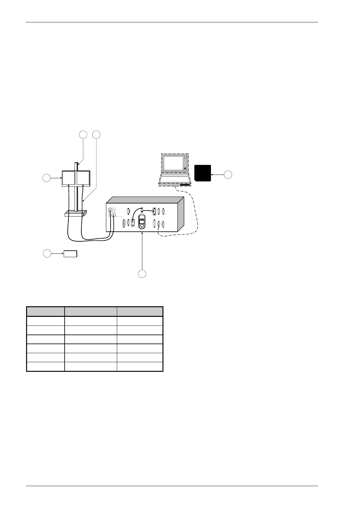
Picture 3-1: system; general view
Abbreviation Term Reference-Code
R reader WR-xxxx
T tag WT-xxxx
A antenna WA-xxxx
M mounting aids WM-xxxx
C rf cable WC-xxxx
S service software (S) WS-xxxx
Table 3-1: terms of the system
The OIS-W system shows a flexible, modular product concept. The reader (R) is in principle separated
from the antenna (A). Thereby the reader (R) may be placed in another environment (temperature,
humidity, explosive atmosphere) than the antenna (A).
Before delivery Baumer Ident will configure and parameterize the OIS-W system based on the respective
application. This procedure allows a short commissioning.
Baumer Ident supplies a service software (S) to optimize the configuration parameters during the
commissioning and for the maintenance. The service software (S) is not necessary during the operation.
Serial interfaces and fieldbus interfaces allow integration in a customer data network or teleservice.

Baumer Ident AG 5 / 6
Author: Clemens Zehnder File: Installation.doc
3.2 Reader
3.2.1 Introduction
A flexible and modular system consisting of the reader (R) and the optional integrated interface unit forms
the basis for the most common possibilities to integrate into a higher-order system. Interfaces with RS 232
and RS 422 are available in the basic reader type. The optional interface unit is necessary for interfaces
with Profibus-DP, InterBus-S, CAN or
Baumer Ident AG 5 / 6
Author: Clemens Zehnder File: Installation.doc
3.2 Reader
3.2.1 Introduction
A flexible and modular system consisting of the reader (R) and the optional integrated interface unit forms
the basis for the most common possibilities to integrate into a higher-order system. Interfaces with RS 232
and RS 422 are available in the basic reader type. The optional interface unit is necessary for interfaces
with Profibus-DP, InterBus-S, CAN or Ethernet.
The reader (R) is designed and built according to the newest state-of-the-art techniques. It contains a
DSP1, a FPGA2 and a DDS3.
Essentially the functions of the reader (R) are realized with a DSP. It is responsible for the reliable
decoding of the reflected microwave signal and for steering and control of the whole unit. The program
modules and the configuration file are saved in a Flash-EPROM. As the functions are realized with
software, application specific modifications or software updates can easily be carried out.
The reader (R) is the most important module of the OIS-W system. It generates the microwave signal to
interrogate a tag, sends is out by the antenna (A), processes the receiving signal, evaluates the code and
communicates the data with selectable serial interfaces or with an optional fieldbus interface to a network.
The OIS-W transponders are fix code tags. The linking of this fix code with an application specific
identification number can be carried out with the help of a look up table within the reader (R) .
One or two antennas(A) can be connected to the reader (R) according to its type. This allows the
realization of the identification points with only one OIS-W system.
The reader (R) can be operated either in the operation mode „event driven“ or „triggered“. The reader (R)
can be triggered either with a digital input or with a telegram from a higher order system. The user has the
choice whether the interrogation signal is constantly on or only if required.
For various additional steering functions as e.g. switching of external loads or interrogation of errors, there
are one or more digital outputs per antenna available according to the reader (R) type. This may possibly
make a PLC or a PC obsolete. For experienc