Baumer Electric OIS-W-WR300303 RF-Identification System User Manual Maintenance
Baumer Electric AG RF-Identification System Maintenance
Contents
- 1. Installation
- 2. Interface
- 3. Maintenance
Maintenance

Technical Documentation
User’s Manual
2000 Baumer Ident AG Switzerland
OIS-W: User's Manual
Service Software Development
PROJECT
PROJECT: USER'S
MANUAL
PROJECT
LEADER: CLEMENS
ZEHNDER
CC: -
SUPPLIER: -
DOCUMENT
INITIAL
DATE: 12. AUGUST 1999
LAST CHANGE: 10. OCTOBER 2000
VERSION: 3.1
E
FILE: MSGY-2001-0305A.DOC

Baumer Ident AG
Author: Clemens Zehnder File: Maintenance-SW.doc
Contents
The Aim of the Document
1 User’s Instructions............................................................................................................................1
1.1 Technical hot line ......................................................................................................................1
1.2 Certification ...............................................................................................................................1
1.3 Warranty....................................................................................................................................1
2 How to install the Service Software based on a PC.......................................................................2
2.1 System Requirements...............................................................................................................2
2.2 How to copy the enclosed Files into the Working Directory......................................................2
2.3 How to install and start-up the Application „DEVELOP.EXE“ with MS-DOS.............................2
2.4 How to install and start-up the Application „Develop.exe“ with Windows 95.............................3
2.5 Starter Picture of the Application „Develop.exe“ .......................................................................4
3 How to operate the Service Software based on a PC ....................................................................5
3.1 Introduction................................................................................................................................5
3.2 Keys and Combinations of Keys of the Man Machine Interface................................................8
4 Description of the Man Machine Interface ......................................................................................9
4.1 Window 1 ..................................................................................................................................9
4.2 Window 2 ................................................................................................................................30
4.3 Window 3 ................................................................................................................................48
5 How to put into Practice .................................................................................................................54
5.1 Logistics ..................................................................................................................................54
5.2 Access Control ........................................................................................................................62
6 If you have a Problem .....................................................................................................................63
7 Remote Diagnostics........................................................................................................................64
8 Glossary ...........................................................................................................................................68
9 Notice................................................................................................................................................69

Baumer Ident AG
Author: Clemens Zehnder File: Maintenance-SW.doc
Contents of the Pictures
Picture 2-1: start up with windows 95 .................................................................................................................................................3
Picture 2-2: Develop.exe start picture.................................................................................................................................................4
Picture 3-1: man machine interface (W).............................................................................................................................................5
Picture 4-1: OIS-W service software development (S01)....................................................................................................................9
Picture 4-2: system information........................................................................................................................................................10
Picture 4-3: operation mode settings................................................................................................................................................12
Picture 4-4: tag structure settings.....................................................................................................................................................16
Picture 4-5: reader settings ..............................................................................................................................................................19
Picture 4-6: look up table .................................................................................................................................................................22
Picture 4-7: interface settings...........................................................................................................................................................24
Picture 4-8: monitor settings ............................................................................................................................................................26
Picture 4-9: aux ports settings..........................................................................................................................................................27
Picture 4-10: off................................................................................................................................................................................30
Picture 4-11: time domain signal......................................................................................................................................................31
Picture 4-12: frequency domain signal .............................................................................................................................................32
Picture 4-13: signal quality monitor ..................................................................................................................................................33
Picture 4-14: system error monitor...................................................................................................................................................34
Picture 4-15: aux flag monitor ..........................................................................................................................................................36
Picture 4-16: bias code ....................................................................................................................................................................37
Picture 4-17: installation and family code.........................................................................................................................................38
Picture 4-18: analyze mode..............................................................................................................................................................39
Picture 4-19: test mode....................................................................................................................................................................40
Picture 4-20: download reader SW...................................................................................................................................................41
Picture 4-21: download FPGA SW ...................................................................................................................................................42
Picture 4-22: load settings from file..................................................................................................................................................43
Picture 4-23: save settings to file .....................................................................................................................................................44
Picture 4-24: load code table from file..............................................................................................................................................45
Picture 4-25: save code table to file .................................................................................................................................................46
Picture 4-26: aux ports and settings.................................................................................................................................................47
Picture 4-27. off................................................................................................................................................................................48
Picture 4-28: time domain signal......................................................................................................................................................49
Picture 4-29: frequency domain signal .............................................................................................................................................50
Picture 4-30: signal quality monitor ..................................................................................................................................................51
Picture 4-31: system error monitor...................................................................................................................................................52
Picture 4-32: aux flag monitor ..........................................................................................................................................................53
Picture 5-1: application logistics; top view........................................................................................................................................54
Picture 5-2: successful identification supplied by the Service Software Basic (S01).........................................................................58
Picture 5-3: control picture identification...........................................................................................................................................59

Baumer Ident AG
Author: Clemens Zehnder File: Maintenance-SW.doc
Contents of the Tables
Table 1-1: area of validity ...................................................................................................................................................................5
Table 3-1: terms of the man machine interface (W)............................................................................................................................5
Table 3-2: contents of window 1 (W1) ................................................................................................................................................6
Table 3-3: contents of window 2 (W2) ................................................................................................................................................6
Table 3-4: contents of window 3 (W3) ................................................................................................................................................7
Table 3-5: contents of window 4 (W4) ................................................................................................................................................7
Table 3-6: keys and combinations of keys of the man machine interface (W) ....................................................................................8
Table 4-1: operation mode settings ..................................................................................................................................................12
Table 4-2: Mmain / MTxuntrig...........................................................................................................................................................13
Table 4-3: reader settings.................................................................................................................................................................20
Table 4-4: InitDelay ..........................................................................................................................................................................20
Table 4-5: DelayRange.....................................................................................................................................................................21
Table 4-6: look up table....................................................................................................................................................................23
Table 4-7: interface settings .............................................................................................................................................................24
Table 4-8: monitor settings ..............................................................................................................................................................26
Table 4-9: aux ports settings ............................................................................................................................................................27
Table 4-10: overview of the operation modes in combination with the timer functions ......................................................................29
Table 4-11: definition Aux In.............................................................................................................................................................47
Table 4-12: definition Aux Out ..........................................................................................................................................................47
Table 5-1: components of the application logistics ...........................................................................................................................54
Table 5-2: configuration parameter...................................................................................................................................................56
Table 8-1: glossary...........................................................................................................................................................................68

Baumer Ident AG
Author: Clemens Zehnder File: Maintenance-SW.doc
The Aim of the Document
The document describes the „Service Software Development“ of the Ident System OIS-W as an user’s
manual. It is addressed to integrators of the system.
The OIS-W hardware is described in the additional document „User’s Manual Hardware“.
For maintenance staff and interested users of the system, a PC based „Service Software Basic“ is
available which is described in the additional document „User’s Manual Service Software Basic“.
Baumer Ident supplies the OIS-W preconfigured and set up in parameters. In the normal case the user
needn’t read the whole document to succeed in putting the system in operation.
This document is based on the system configuration below:
Terms Reference-Code
Reader WR-xxxx (without WR-xx2x)1
with DSP SW 2.30
Tag WT-xxxx
Antenna WA-xxxx
Mounting Aids WM-xxxx
RF Cable WC-xxxx
Service Software WS-02.30
Table 1-1: area of validity
1 WR-xx2x (with Profibus-DP) is Not yet released!

Baumer Ident AG 1 / 1
Author: Clemens Zehnder File: Maintenance-SW.doc Version 3.0 e
1 User’s Instructions
1.1 Technical hot line
Please report any problems to:
• Baumer Ident @ Baumer Electric AG
Hummelstrasse 17
CH-8500 Frauenfeld
Switzerland
Tel.: +41-52-728 11 22
Fax: +41-52-728 11 44
e-mail: dzehnder@baumerelectric.com
1.2 Certification
The OIS-W was designed, constructed and certified according to the following references:
• BAPT 211 ZV 037/2050; April 97
Bundesamt für Post und Telekommunikation (D); „Zulassungsvorschrift für Funkanlagen für
Identifizierungszwecke“
• BAKOM SR 784.103.12 / 1.33; 1.6.1996
Bundesamt für Kommunikation (CH), „Technische Anforderungen für Funkanlagen mit geringer
Reichweite die im Frequenzbereich 1 GHz bis 25 GHz auf Sammelfrequenzen betrieben
werden"
• I-ETS 300 440; Dec. 1995
ETSI, „Radio Equipment and Systems (RES); Short range devices; Technical characteristics
and test methods to be used in the 1 GHz to 25 GHz frequency range“, Dec. 1995.
1.3 Warranty
This Baumer Ident product is warranted against defects in material and workmanship for a period of one
year from date of delivery. During the warranty period, Baumer Ident will, at its option, either repair or
replace products which prove to be defective.
Baumer Ident warrants that its software and firmware designated by Baumer Ident for use with an OIS-W
will execute its programming instructions when properly installed on that system. Baumer Ident does not
warrant that the operation of the system will be uninterrupted or error-free.
The foregoing warranty shall not apply to defects resulting from improper or inadequate operation by
buyer, buyer-supplied software or interfacing, unauthorized modification or misuse, operation outside of
the environmental specifications for the product, or improper site preparation or maintenance. Baumer
Ident will decline liability for units that have been opened without permission of Baumer Ident.

Baumer Ident AG 2 / 3
Author: Clemens Zehnder File: Maintenance-SW.doc Version 3.0 e
2 How to install the Service Software based on a PC
To reconfigure, to optimize and for maintenance of the reader a service software is necessary. Please
install it on a laptop or PC. The service PC and the service software are no longer required for the actual
operation.
2.1 System Requirements
Minimum:
• Processor Intel 486 / 66 MHz
• MS DOS 6.20
• RAM 520 Kbytes free memory (MS-DOS)
• 1 Mbytes hard disk
Optimum:
• Processor Intel 586 / 100 MHz or better
• Microsoft Windows 95 / 98 (service software is a MS DOS application)
• RAM >8 Mbytes
• Hard disk >10 Mbytes
• UART with FIFO
The following are not supported at the moment:
• Microsoft Windows NT
2.2 How to copy the enclosed Files into the Working Directory
Copy the following files from the supplied floppy disk into the working directory on your service PC.
• Develop.exe MS DOS Application
• Help.fon required fonts
• Modern.fon required fonts
• Roman.fon required fonts
• Script.fon required fonts
• OISW.INI defines the colors of the screen display and functions of the keys F1 - F12
2.3 How to install and start-up the Application „DEVELOP.EXE“ with MS-DOS
If you want to start up the application with MSDOS execute one of the following commands:
• C:\PATH...\Develop.exe COM1 BAUD115200 1 // if you use COM1
• C:\PATH...\Develop.exe COM2 BAUD115200 // if you use COM2
• Press „Enter“.
1 Please note the capitol letters and the spaces!
Baumer Ident AG 3 / 4
Author: Clemens Zehnder File: Maintenance-SW.doc Version 3.0 e
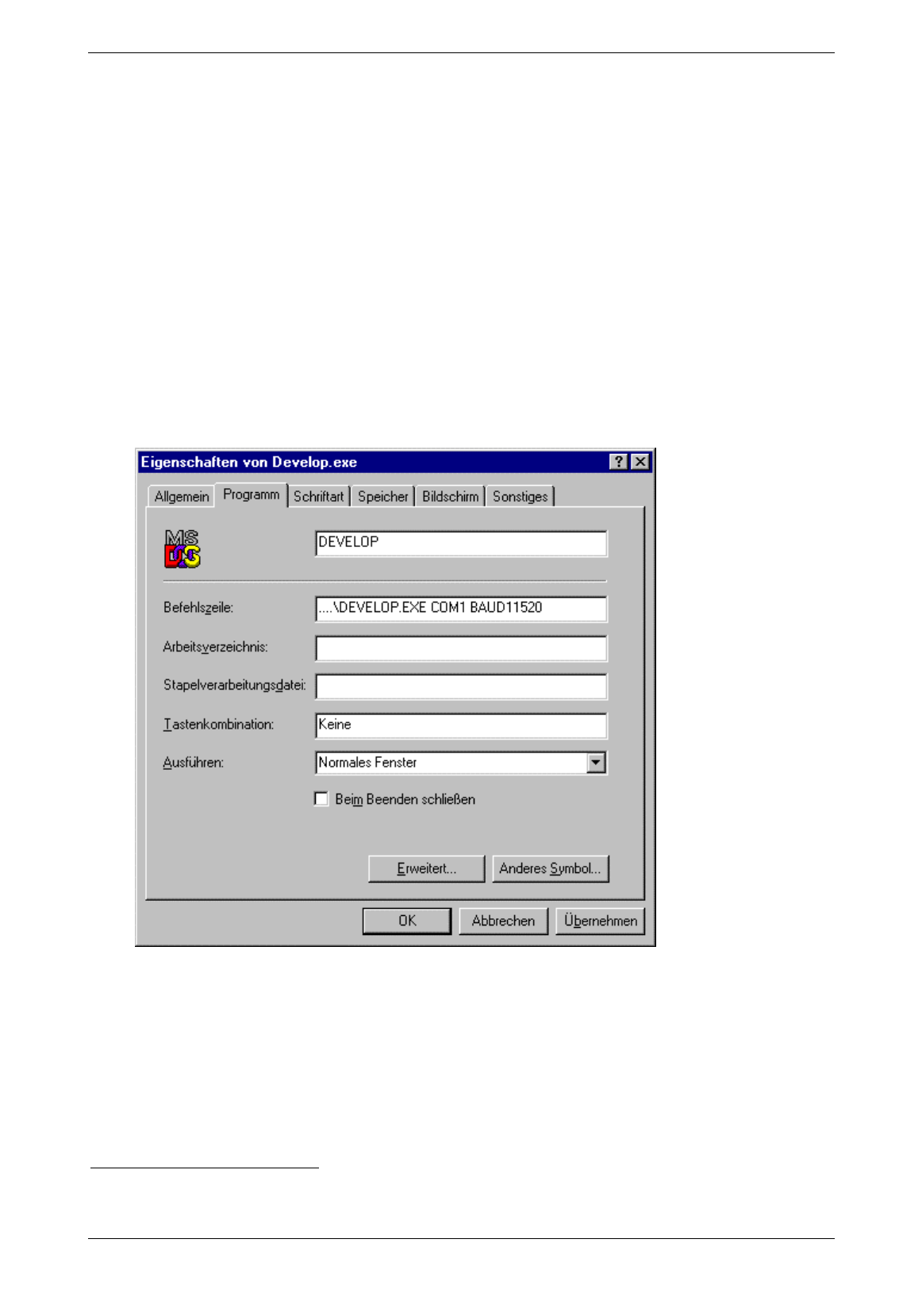
2.4 How to install and start-up the Application „Develop.exe“ with Windows 95
If you want to use the application with Windows95 proceed as follows:
1. Create a link of the file Develop.exe into the path:
C:\Windows\Startmenü
2. Click with right mouse key on „Linking of Develop.exe“!
3. Click on „Properties“!
4. Click on „Program“!
5. Supply the instruction line with:
..\Develop.exe COM1 BAUD115200 1 //if you use COM1
..\Develop.exe COM2 BAUD115200 //if you use COM2
Picture 2-1: start up with windows 95
6. Call Develop.exe in start menu!
1 Please note the capitol letters and the spaces!
Baumer Ident AG 4 / 5
Author: Clemens Zehnder File: Maintenance-SW.doc Version 3.0 e
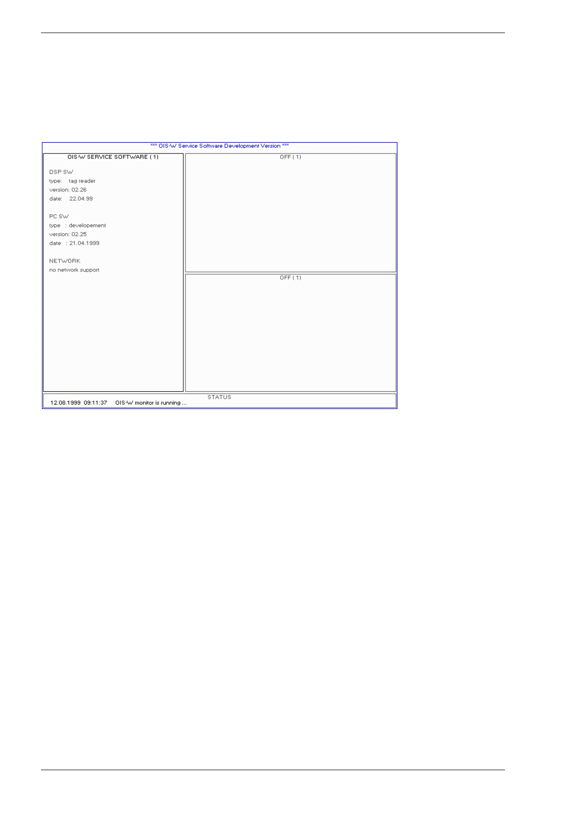
2.5 Starter Picture of the Application „Develop.exe“
After successful start up the following starter picture appears:
Picture 2-2: Develop.exe start picture
Please note that the entries under DSP SW (type, version, date) only appear if the service PC is
connected to the reader (R) and the communication has started up successfully.
Baumer Ident AG 5 / 6
Author: Clemens Zehnder File: Maintenance-SW.doc Version 3.0 e
3 How to operate the Service Software based on a PC
3.1 Introduction
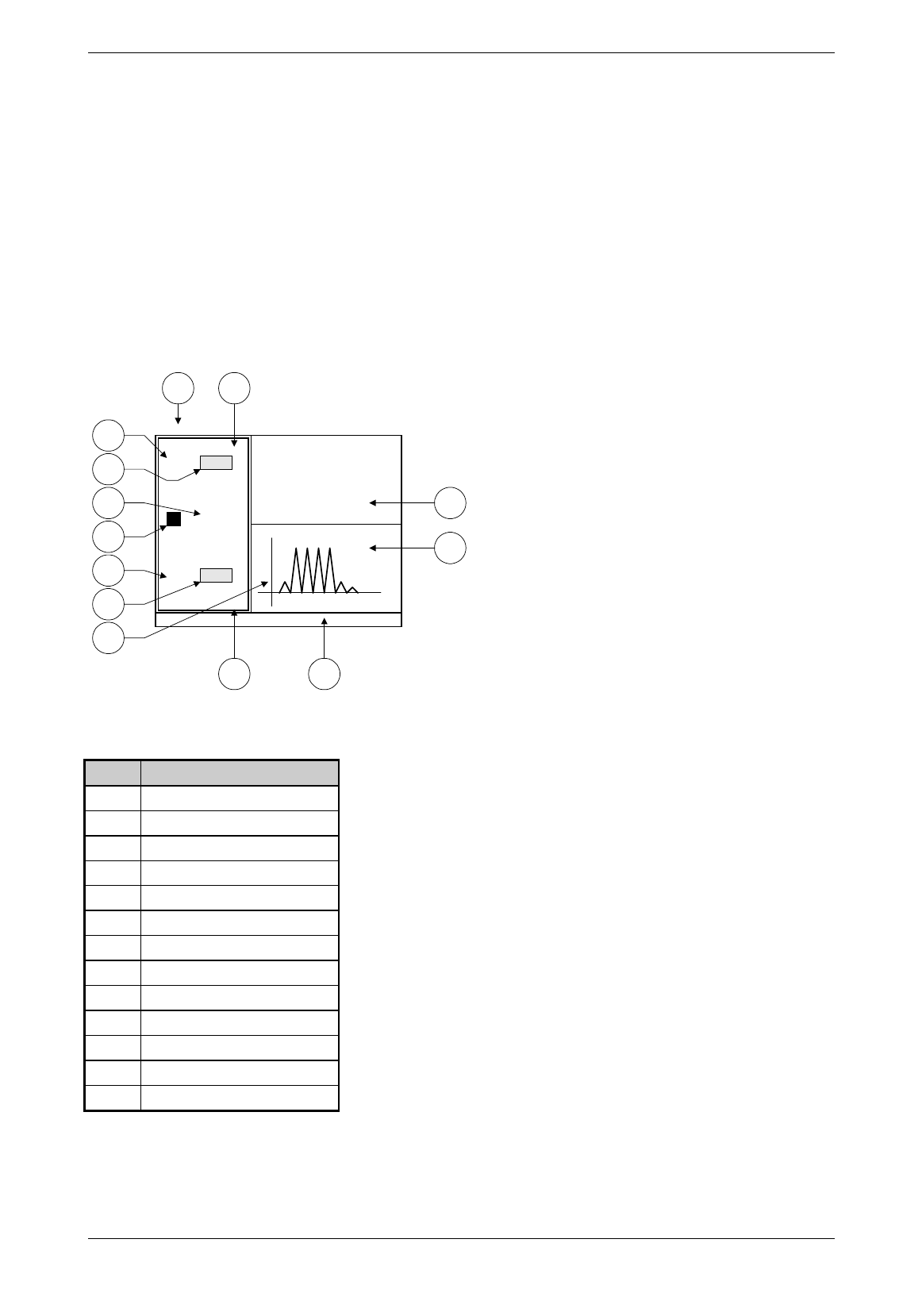
The service monitor is divided into four windows. Each window contains several pages. The user selects
one window as active and can turn its pages like in a book.
W1
W2
W3
W4
W
S/N 35
ID valid
Navg 5
AW
DG
IM
DIM
FL
DFL
OM
DOM
Picture 3-1: man machine interface (W)
Abb. Term
W Man machine interface
W1 Window 1
W2 Window 2
W3 Window 3
W4 Window 4
AW Active window
DG Diagram
IM Input mask
DIM Description of the input mask
FL Flag
DFL Description of the flag
OM Output mask
DOM Description of the output mask
Table 3-1: terms of the man machine interface (W)

Baumer Ident AG 6 / 7
Author: Clemens Zehnder File: Maintenance-SW.doc Version 3.0 e
3.1.1 Overview
Man machine interface (W)
The man machine interface (W) contains four different windows. Each window is like a book and consists
of several pages. The user selects the active window and chooses the required page.
Window 1 (W1)
Page Term Contents
1 OIS-W Service Software (1) • Indicates the DSP SW Version
• Indicates the PC SW Version
2 System Information (2) • Indicates the status of the identification
• Indicates the reason for an invalid identification
• Indicates the operation mode
• Indicates the chosen parameters for the code processing
3 Operation Mode Settings (3) • Input and display of the operation mode
4 Tag Structure Settings (4) • Input and display of the tag structure
5 Reader Settings (5) • Input and display of the reader parameters
6 Interface Settings (6) • Input and display of the parameters of the serial interface RS 232 (R13) and the serial
interface RS 422 (R38)
7 Monitor Settings (7) • Input and display of the monitor parameters
8 Aux Port Settings (8) • Input and display of the auxiliary port parameters
Table 3-2: contents of window 1 (W1)
Window 2 (W2)
Page Term Contents
1 off
2 Time Domain Signal • Indicates the time domain signal after the A/D converter
3 Frequency Domain Signal • Indicates the calculated frequency domain signal
4 Signal Quality Monitor • Indicates errors and status information for every code block
5 System Error Monitor • Indicates errors and status information for the reader
6 Aux Flag Monitor • Indicates the status information of Aux Ports and Aux Flags
7 enter Bias code • Not released!
8 Installation and Family Code • Not released!
9 Analyze Mode •
Indicates the numbers of correct, rejected and false codes; for test purposes only
10 Test Mode •
Not released!
11 Download Reader SW • Installs a new DSP software from the working directory of your service PC
12 Download FPGA SW • Installs a new FPGA software from the working directory of your service PC
13 Load Settings from File • Installs a new configuration file from the working directory of your service PC
14 Save Settings to File • Saves the configuration file from the reader to the working directory of your service PC
15 Load Code Table from File • Installs a new code table from the working directory of your service PC to the reader
16 Save Code Table to File • Saves the code table from the reader to the working directory of your service PC
17 Aux Ports Monitor &
Settings
• Displays the status of the digital inputs
• Setting of the digital outputs
Table 3-3: contents of window 2 (W2)

Baumer Ident AG 7 / 8
Author: Clemens Zehnder File: Maintenance-SW.doc Version 3.0 e
Window 3 (W3)
Page Term Contents
1 off
2 Time Domain Signal • Indicates the time domain signal after the A/D converter
3 Frequency Domain Signal • Indicates the calculated frequency domain signal
4 Signal Quality Monitor • Indicates errors and status information for every code block
5 System Error Monitor • Indicates errors and status information for the reader
6 Aux Flag Monitor • Indicates the status information of Aux Ports and Aux Flags
Table 3-4: contents of window 3 (W3)
Window 4 (W4)
Page Term Contents
1 Status •
Indicates status information about the service software (S)
• Indicates help text during input of parameters
Table 3-5: contents of window 4 (W4)
Active window (AW)
The user recognizes the active window through the lit yellow frame and through the yellow header. The
active window can be changed with the key „Tab“. Basically entries can only be made in the active mode.
Diagram (DG)
Graphic designs are used in the form of diagrams in window 2 (W2) and window 3 (W3).
Input mask (IM)
The concrete values of the configuration parameters and the name of the files to be transferred are to be
put into input masks (IM).
Description of the input mask (DIM)
Each input mask (IM) is uniquely labeled.
Flag (FL)
Operation status and errors are shown with flags (FL) which change their color according to their status.
Description of the flag (DFL)
Each flag (FL) is uniquely labeled.
Output mask (OM)
Important information about the current identification are indicated with the help of output masks (OM).
Description of the output mask (DOM)
Each output mask (OM) is uniquely labeled.

Baumer Ident AG 8 / 9
Author: Clemens Zehnder File: Maintenance-SW.doc Version 3.0 e
3.2 Keys and Combinations of Keys of the Man Machine Interface
These keys and combinations of keys initiate the following actions:
Keys Action
ESC, 'x', 'q', 'X' , 'Q' Quit the application
'1' Go to next page of window 1
'2' Go to next page of window 2
'3' Go to next page of window 3
TAB Change active window. The user recognizes the active window through the lit yellow frame and
through the yellow header. Basically entries can only be made in the active mode.
PAGE UP Go to next page of active window
PAGE DOWN Go to previous page of active window
CTRL + PAGE UP Fast forward of active window (+ 3 pages)
CTRL + PAGE DOWN Fast backward of active window (+ 3 pages)
HOME Go to the first page of active window
END Go to the last page of active window
'f' Freeze display
RETURN or e Edit parameters in the active window. Each input in an input mask (IM) has to be followed by a
„Return“. Then the cursor goes to the next input mask (IM). To accept the new entries or to
execute the new commandos the last input mask (IM) of the active window has to be left with
„Return“. If the input mode is quitted with „ESC“, all the entries made are not accepted.
'r' Reset reader
't' Software trigger
In triggered mode the reader is triggered to start an identification. On page „monitor settings“ the
user can configure on which antenna an identification shall be made.
‘m’ Reset AUX port flags; if window ‘Aux Ports Monitor & Settings’ or window ‘Aux Flag Monitor’ or
window ‘ID and AUX Port Information’ is visible, an ACK message for AUX_REP is sent in order
to reset the AUX port flags.
'B' Change the baud rate of the service software (S); (doesn’t change baud rate on DSP)1
'F5' Combined display which is used as a standard window combination to observe the identification.
The standard window combination is saved in the file OIS_W.ini.
'd' Display which is used to observe the outgoing data telegram at serial interface RS 232 (R13).
's' Save all the relevant reader data into a data file into the working directory. This file is required
for further analysis in case of identification problems.
Table 3-6: keys and combinations of keys of the man machine interface (W)
1 The baud rates always have to be adapted on the PC (installation command) and on the DSP (configuration file)
Baumer Ident AG 9 / 10
Author: Clemens Zehnder File: Maintenance-SW.doc Version 3.0 e
4 Description of the Man Machine Interface
4.1 Window 1
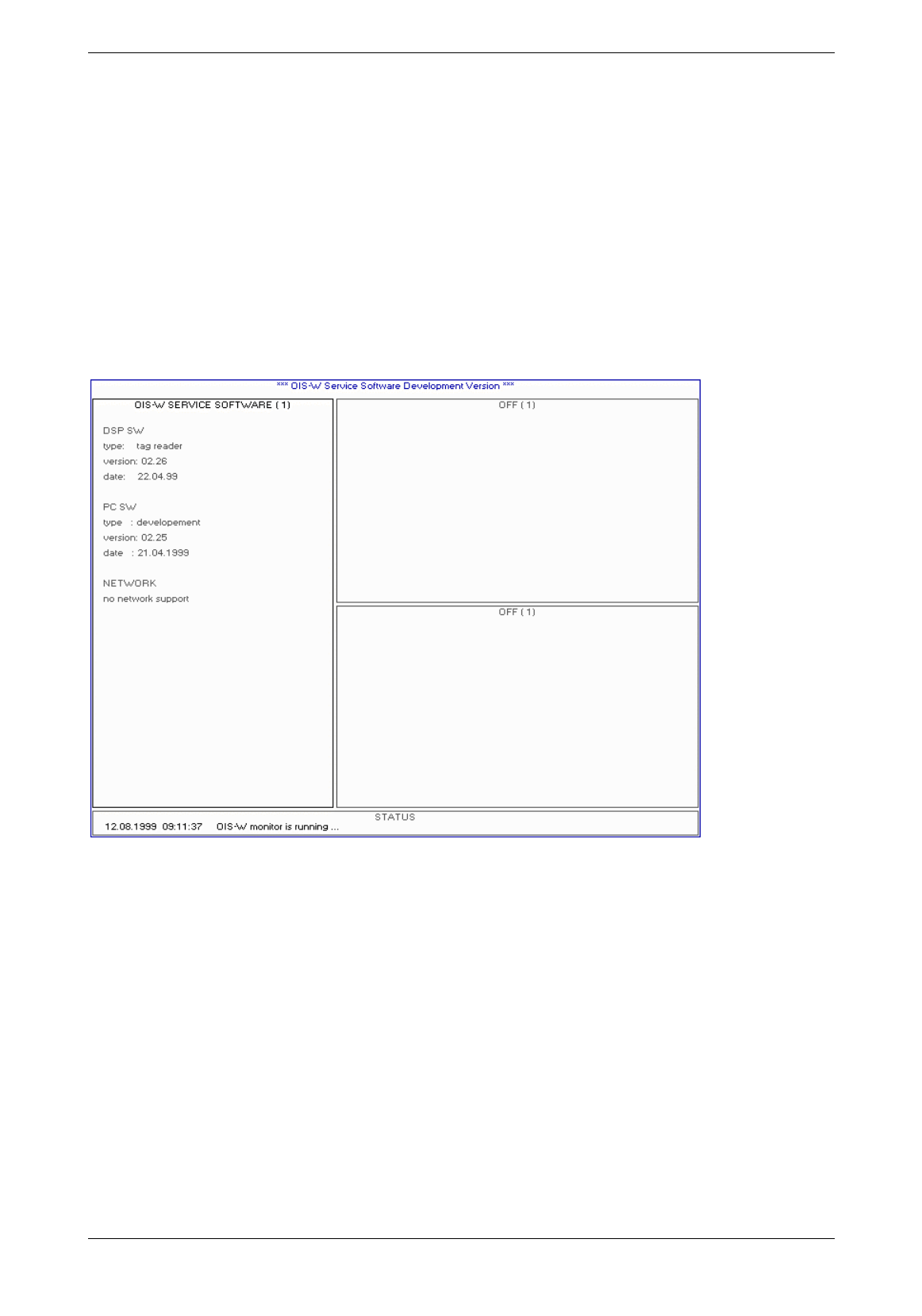
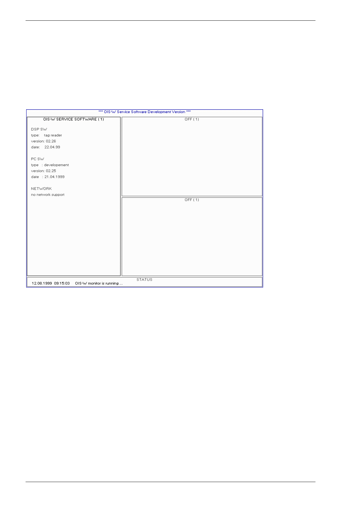
4.1.1 Page 1: OIS-W Service Software
Picture 4-1: OIS-W service software development (S01)
DSP Software Info
• Type: tag reader
• Version: xx.xx
• Date: xx.xx.xx
PC Software Info
• Type: basic / development / professional
• Version: xx.xx
• Date: xx.xx.xx
Network
Not yet released!
Baumer Ident AG 10 / 11
Author: Clemens Zehnder File: Maintenance-SW.doc Version 3.0 e
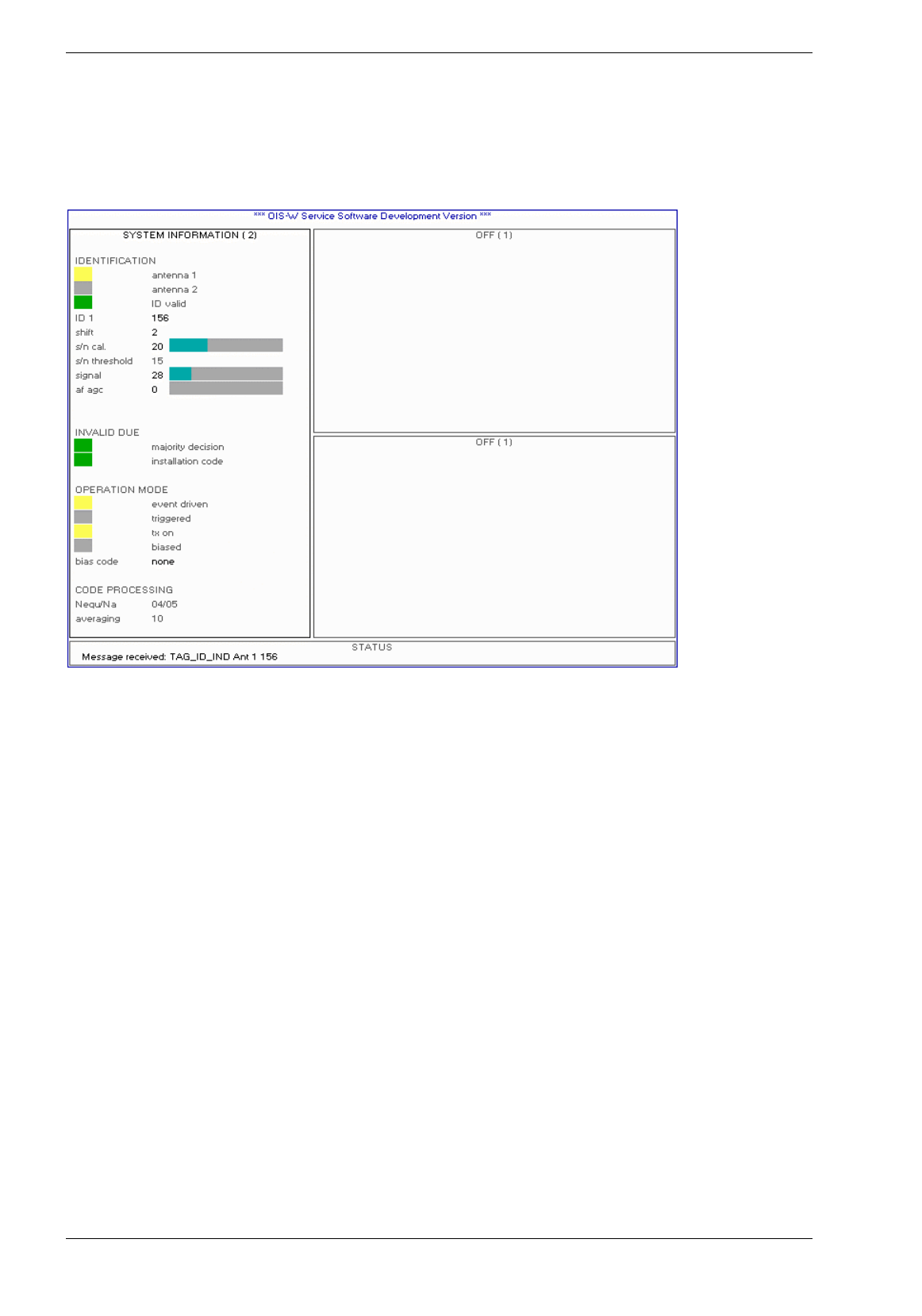
4.1.2 Page 2: System Information
All parameters which are mentioned in the following text are explained in detail in chapters 4.1.3 - 4.1.5.
Picture 4-2: system information
Antenna 1 / Antenna 2
If the flags shine yellow the respective antenna is used. The display corresponds to the parameter
„Reader Settings: Ant“.
ID valid
The flag shines green if a valid tag (T) is recognized. It gives the same information as the LED detection
status of ant 1 (R10) on the front panel.
ID
This output mask (OM) shows the decoded code.
Shift
This output mask (OM) indicates where the calibrator has been detected in the unit [Bin] within the delay
range.
S/N cal.
This output mask (OM) indicates the measured signal-to-noise ratio in the unit [dB]. The signal is
measured at the recognized calibrator and the noise within the range defined with the parameter „Reader
Settings: Tnoise0“.

Baumer Ident AG 11 / 12
Author: Clemens Zehnder File: Maintenance-SW.doc Version 3.0 e
S/N Threshold
This output mask (OM) indicates the S/N threshold in the unit [dB]. It corresponds to the parameter
„Reader Settings: SNR“.
Signal
This output mask (OM) indicates the signal level of the calibrator in the unit [dB].
AF AGC
This output mask (OM) indicates the value of the automatic gain control. The user doesn’t have the
possibility the change this parameter.
Invalid Due
If this flag shines red the condition „number of equal codes out of number of measurements“ is not met.
This condition is defined through the parameters „Reader Settings: Nequ and Na“.
If the flag shines green the condition is met.
Event Driven
If this flag shines yellow the operation mode „Event Driven Mode“ is selected. The flag corresponds to the
parameter „Operation Mode Settings: Mmain“.
Triggered
If this flag shines yellow the operation mode „Triggered Mode“ is selected. The flag corresponds to the
parameter „Operation Mode Settings: Mmain“.
TX ON
If this flag shines yellow the reader (R) always sends out an interrogating signal. If the flag doesn’t shine
the reader (R) sends out an interrogating signal only if the respective antenna (A) is triggered. The flag
corresponds to the parameter „Operation Mode Setting: MTxuntrig“.
Bias Code
Not yet released!
Nequ/Na
This output mask (OM) shows the values of the parameters „Reader Settings: Nequ/Na“ an. These
parameters are used for the condition „number of equal codes out of number of measurements“.
Averaging
This output mask (OM) indicates the value of the parameter „Reader Settings: Navg“. This parameter is
used for the approximate, moving average and defines the number of measurements.
Baumer Ident AG 12 / 13
Author: Clemens Zehnder File: Maintenance-SW.doc Version 3.0 e
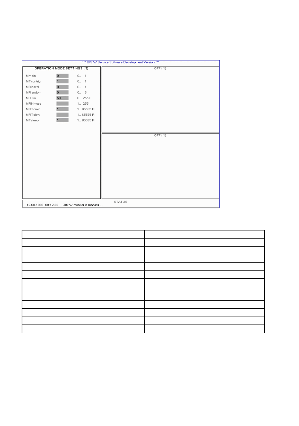
4.1.3 Page 3: Operation Mode Settings
Picture 4-3: operation mode settings
Name Description Range Default Remarks
Mmain main operation mode 0..1 0 0=event driven,1=triggered
Mtxuntrig transmitter state when not triggered;
for triggered and event driven mode
0..1 1 0=off,1=on
Mbiased biased mode 0..1 0 0=off,1=on
Mrandom random mode; ramp timing distributions 0..3 0 0=off, 1=uniform distributed, 2,3=not yet released
MRTm max. measurements per block 0..255 25 the min measurement block corresponds to
Parameter „Reader Settings: Nequ“.
Also used for triggered mode when random = OFF.
MRNmess number of measurement blocks 1..255 5
MRTdmin min. random delay 1..65535 5 in ramp durations1
MRTdlen range of random delay 1..65535 50 in ramp durations
Mtsleep sleep time 1..65535 50 in ramp durations
Table 4-1: operation mode settings
1 Ramp duration = 20 ms

Baumer Ident AG 13 / 14
Author: Clemens Zehnder File: Maintenance-SW.doc Version 3.0 e
Mmain / MTxuntrig
Operation mode Mmain MTxuntrig Description
Event Driven Mode TX
On
0 1 The reader (R) always sends out an interrogating signal and the identification
is always activated.
Event Driven Mode TX Off 0 0 The reader (R) sends out an interrogating signal and the identification is
activated only if the trigger input is on „1“.
Triggered Mode TX On 1 1 The reader (R) always sends out an interrogating signal. But the
identification starts only if the reader (R) is triggered.
Three ways to trigger:
• trigger input on „1“
• via telegram
• for test purpose via service PC keyboard „t“
Triggered Mode TX Off 1 0 The reader (R) doesn’t send out an interrogating signal on stand by mode. If
the reader (R) is triggered it sends out an interrogating signal. After a
successful identification or after a certain time the reader (R) returns back to
stand by mode.
Three ways to trigger:
• trigger input on „1“
• via telegram
• for test purpose via service PC keyboard „t“
Table 4-2: Mmain / MTxuntrig
Mbiased
Not yet released!
Baumer Ident AG 14 / 15
Author: Clemens Zehnder File: Maintenance-SW.doc Version 3.0 e
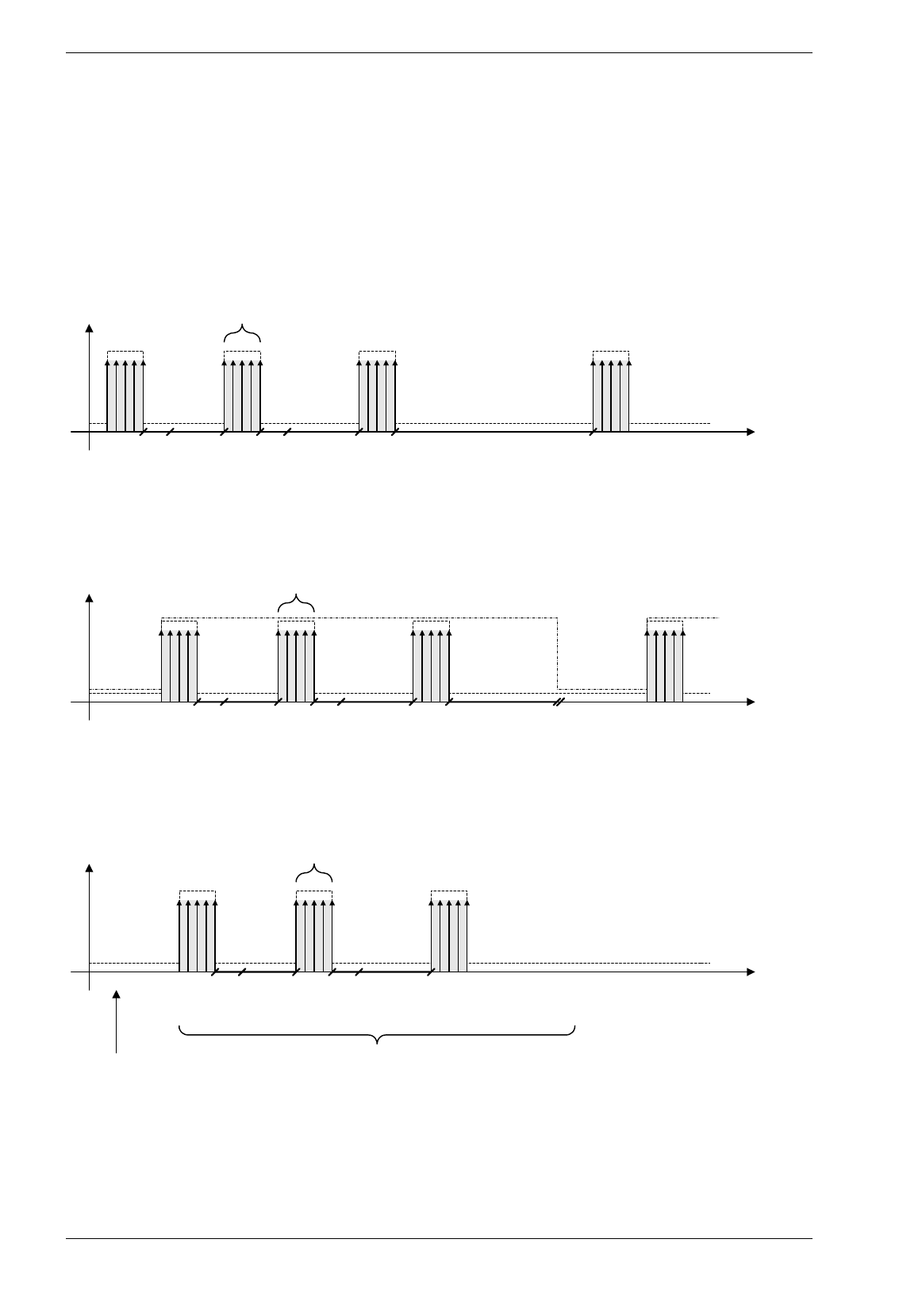
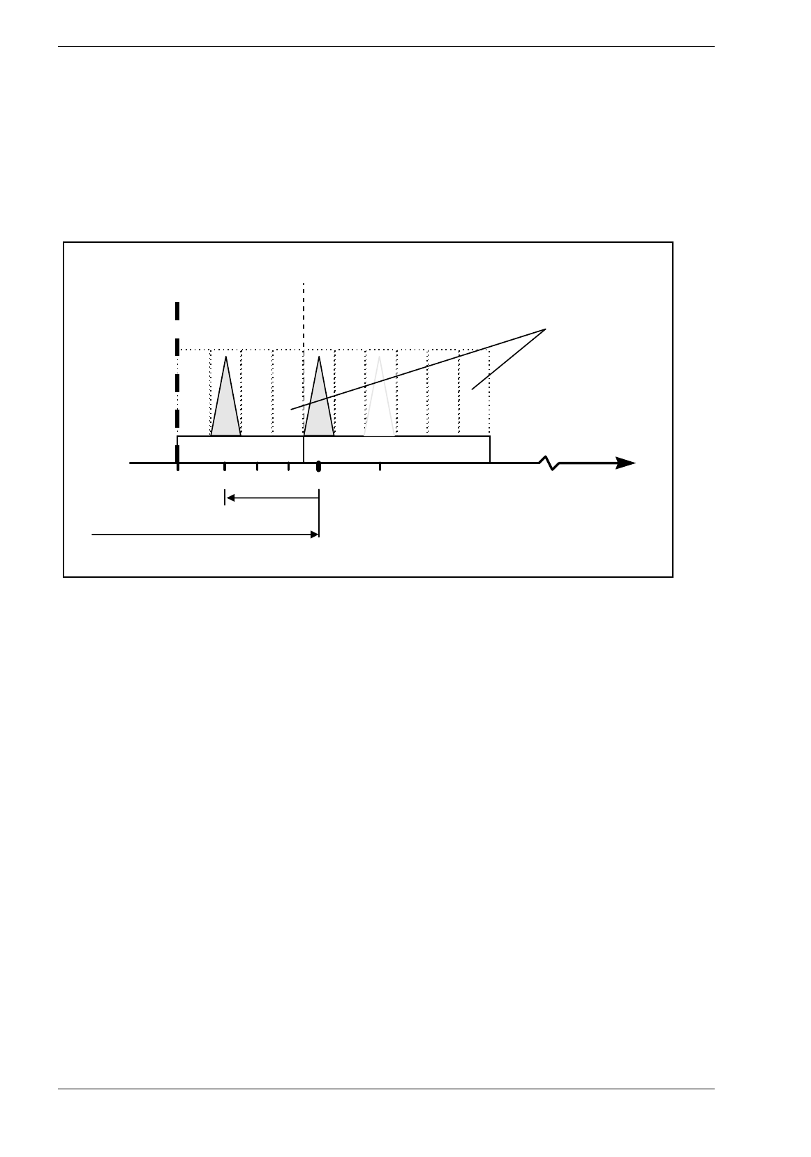
Mrandom
Random mode means that the reader will be switched on for reading during an allowed interval randomly.
The random mode reduces the mutual influences of the readers by using different time slots.
Antenna toggling is not allowed for random mode. The reader will automatically turn to event driven mode
alternating the antennas as if random mode was not set.
Random Mode combined with Event Driven Mode TX-ON
MRTdmin
MRTdlen
MRTdmin
MRTdlen
MTsleep
Read 1:
no valid Tag Read 2:
no valid Tag
Read 2:
valid Tag
t
MRTm
RF On
Random Mode combined with Event Driven Mode TX-OFF
MRTdmin
MRTdlen
MRTdmin
MRTdlen
MTsleep
Read 1:
no valid Tag Read 2:
no valid Tag
Read 2:
valid Tag
t
MRTm
RF On
Trigger
Level On
MRNmess
Random Mode combined with Trigger Mode TX-OFF
MRTdmin
MRTdlen
MRTdmin
MRTdlen
Read 1:
no valid Tag Read 2:
no valid Tag
Read 2:
valid Tag
t
MRTm
RF ON
Trigger
Picture 4-1: random mode

Baumer Ident AG 15 / 16
Author: Clemens Zehnder File: Maintenance-SW.doc Version 3.0 e
MRTm
This parameter defines the number of measurements per blocks.
MRNmess
This parameter defines the number of measurement blocks.
MRTdmin
This parameter defines the minimum delay time after a block.
MRTdlen
This parameter defines the range of the random delay.
Mtsleep
This parameter defines the sleep time after a successful identification.
Overview of random parameters
Use the random parameters in combination with the corresponding modes as described below:
Operation mode Mmain Mtxuntrig Mrandom MRTm MRNmess MRTdmin MRTdlen MTsleep
Event Driven Mode TX On 0 1 1 X 1 n.r.
2 X X X
Event Driven Mode TX Off 0 0 1 X n.r. X X X
Triggered Mode TX On 3 1 1
Triggered Mode TX Off 1 0 1 X X X X n.r.
Table 4-1: random mode
1 X: value according to the definition of the range of the respective parameter
2 n.r. :not relevant in thois combination
3 doesn’t make any sense
Baumer Ident AG 16 / 17
Author: Clemens Zehnder File: Maintenance-SW.doc Version 3.0 e
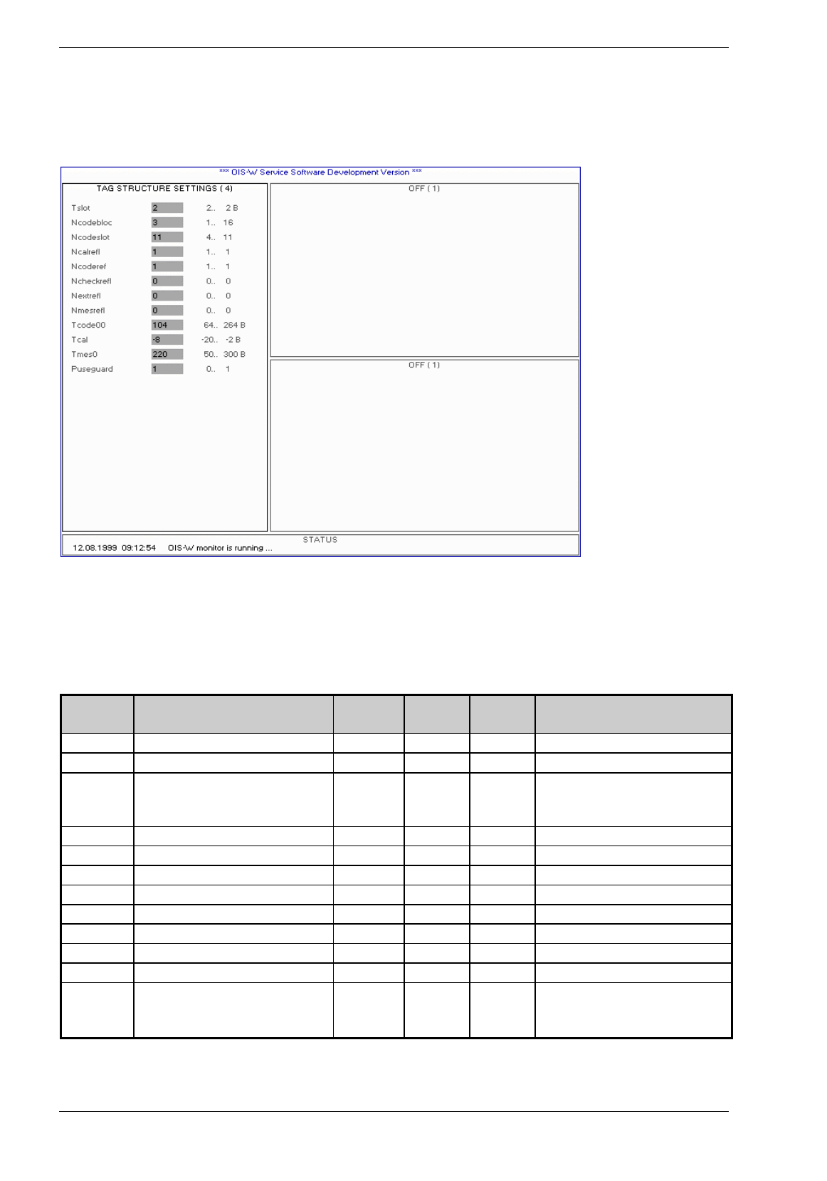
4.1.4 Page 4: Tag Structure Settings
Picture 4-4: tag structure settings
The tag structure makes possible a lot of variations for current and future tag designs. For the current D3
and D4 tags the user can work with the two standard configurations as described in Table 4-2: tag
structure settings.
Term Description Range D3-Tag
WT-0X1X
D4-Tag
WT-0X2X
Remarks
Tslot Slot width 2B 2 2
B=FFT bin (=12.5ns)
Ncodebloc Number of code blocks 1 to 16 3 4
Ncodeslot Slots per code block 4 to 11 11 11
if 11 slots are used, the guard slot is
mandatory (no tap in slot 11
allowed!)
Ncalrefl Number of calibration reflectors 1 1 1
Not yet released
Ncoderef Number of reflectors per code block 1 1 1
Not yet released
Ncheckrefl Number of checksum reflectors 0 0 0
Not yet released
Nextrefl Number of code extension reflectors 0 0 0
Not yet released
Nmesrefl Number of measurement reflectors 0 0 0
Not yet released
Tcode00 Position of first code slot 64 ... 264 B 104 104
1000 ... 3300 ns
Tcal Position of calibrator reflector -2 ... -20 B -8 -8
rel. to Tcodeslot00
Tmes0 Position of first measurement zone 50 ... 300 B 220 220
625 ... 3750 ns; Not yet released
Puseguard Use of guard slot in code blocks 0, 1
1 1
1: with guard slot
0: no guard slot, min spacing of
reflectors is 2 slots
Table 4-2: tag structure settings

Baumer Ident AG 17 / 18
Author: Clemens Zehnder File: Maintenance-SW.doc Version 3.0 e
Tslot
Defines the number of Bins per Slot. At the moment the value is fixed at 2.
Ncodebloc
Defines the number of codeblocks respectively the number of characters per code.
Tag Ncodebloc Code Example
D3 3 321
D4 4 4321
D5 5 54321
Table 4-3: Ncodebloc
Mcodeslot
Defines the number of slots per codeblock.
Tag Ncodeslot Code Range
D3 3 000-222
D3 4 000-333
D3
111 000-999
Table 4-4: Mcodeslot
Mcalrefl
Not yet released!
Ncoderef
Not yet released!
Ncheckrefl
Not yet released!
Nextrefl
Not yet released!
Nmesrefl
Not yet released!
1 10 Slots plus 1 guard slot
Baumer Ident AG 18 / 19
Author: Clemens Zehnder File: Maintenance-SW.doc Version 3.0 e
Tcode00
Defines the first code slot of the tag structure (without cable and air delay).
Tcal
Defines the position of the calibrator reflector with reference to T00.
T
C-3
T
00(1)
T
02(2)
Time
02
00
01
03
05
•••
Calibration Zone CAL
Code Bloc 0
Code Slots
Calibration slots
R
00(1)
R
02(2)
T
min
Tcode
00
Guard Slots
= Special Code Slots
06
-2
-4
-3
-1
Tcal
Picture 4-2: Tcode00, Tcal
Tmes0
Not yet released!
Puseguard
Not yet released!
Baumer Ident AG 19 / 20
Author: Clemens Zehnder File: Maintenance-SW.doc Version 3.0 e
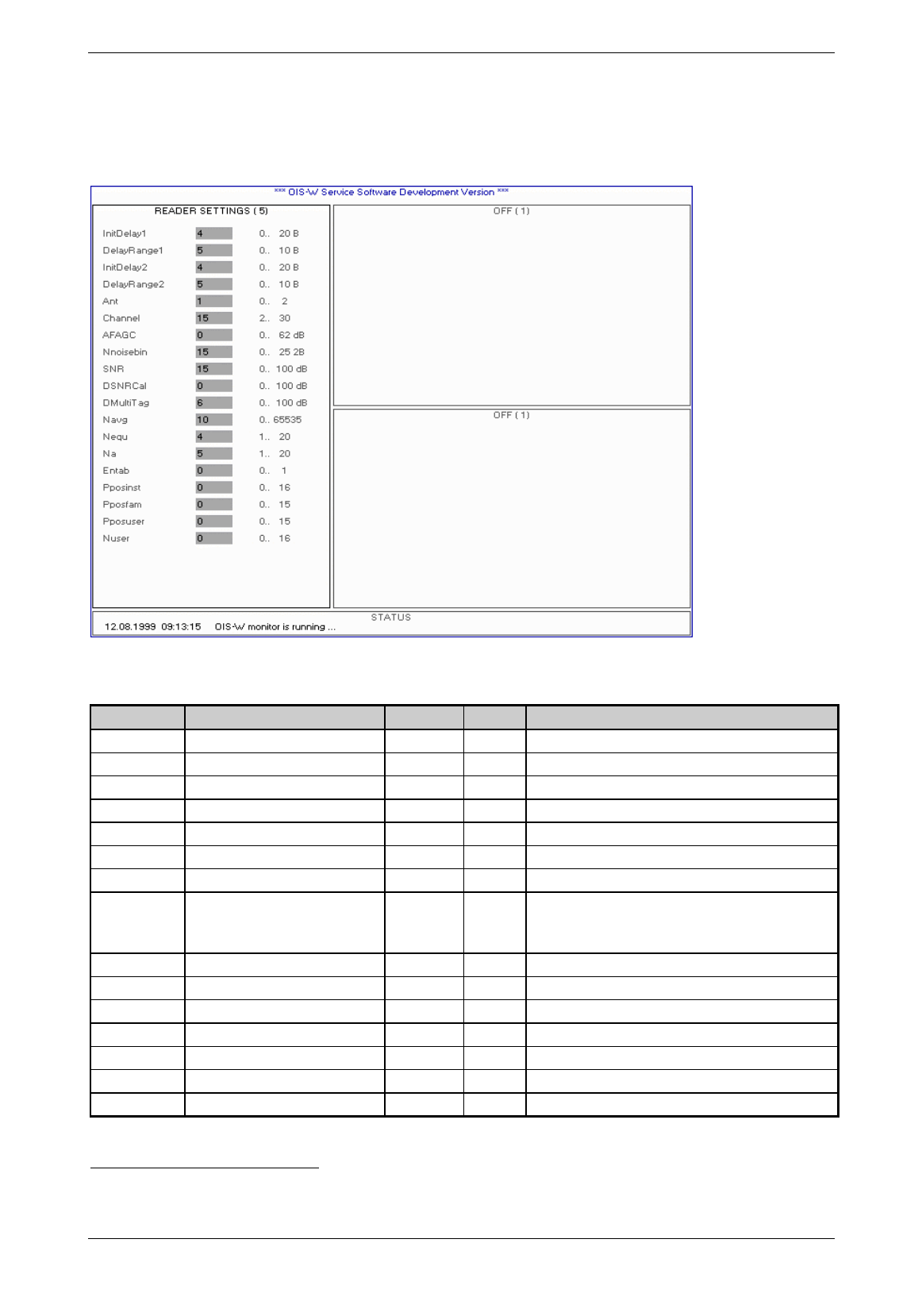
4.1.5 Page 5: Reader Settings
Picture 4-5: reader settings
Term Description Range Default Remarks
InitDelay1 initial delay antenna 1 0…20B1 2 reader & cable delays
DelayRange1 delay search range antenna 1 0…10B 5 air delay (6.6ns/m)
InitDelay2 initial delay antenna 2 0…20B 2 reader & cable delays
DelayRange2 delay search range antenna 2 0…10B 5 air delay (6.6ns/m)
Ant select antenna pair 0, 1, 2 0 o = both alternating; 1=Ant 1; 2=Ant 2
Channel frequency channel 2 ... 30 15 start frequency
AFAGC NF AGC attenuation (dB) 0 .. 62 dB 0 0: auto, 1 ... 62: fixed
Tnoisebin number of Bins used for noise
average left and right from
reflector slot
0 ... 25 2B 15 0: noise will be zero
Note that twice Noisebin are used for calculation!
SNR signal to noise ratio threshold 0...100 dB 15
DSNRCal delta SNR for calibrator 0...100 dB 1 relative to SNR
DmultiTag multi-tag threshold 0...100 dB 5 relative to strongest peak in block or zone
Navg number of averages 0 ... 65353 1
Nequ number of equal ID's 1…20 3 Nequ ≤ Na, otherwise majority decision switched off
Na number of acquisitions 1…20 5
Entab disable / enable look up table 0...1 0 0 = disabled / 1 = enabled
1 Unit Bin (B). 1 Bin corresponds to 12.5 ns.
Baumer Ident AG 20 / 21
Author: Clemens Zehnder File: Maintenance-SW.doc Version 3.0 e
Term Description Range Default Remarks
Pposinst first installation code block 0 ... 16 0 currently not used
Pposfam first family code block 0 ... 15 0 currently not used
Pposuser first user code block 0…15 0 currently not used
Nuser number of user code blocks 0...16 4
Table 4-3: reader settings
InitDelay1 / InitDelay2
This parameter corresponds to the signal propagation within the reader (R) and the rf cable (C). InitDelay
is set separately for each antenna (A). For the calculation only the length of one rf cable (C) is used; i.e.
the distance between reader (R) and antenna (A).
Low-Cost rf cable Low-Loss rf cable
WC-0xxx WC-1xxx
Cable length InitDelay InitDelay
[m] [bin] [bin]
2.5 3 3
3 4 3
5 5 5
10 10 8
15 14 11
20 18 14
25 22 17
Table 4-4: InitDelay
Example:
If you use the following rf cable (C):
• Ant 1: 2 x 5m low-lost rf cable (C) WC-0xxx
• Ant 2: 2 x 25m low-loss rf cable (C) WC-1xxx
Set the following values:
⇒ InitDelay1: 5
⇒ InitDelay2 17
DelayRange1 / DelayRange2
This parameter defines the length of the reading range which is considered when decoding the signal.
DelayRange is to be set separately for each antenna (A). Please note that you only change the parameter
for the internal decoding. This means that only tags(T) are decoded which are within the limits defined by
the parameters InitDelay and DelayRange. These parameters don’t influence the maximum reachable
reading range of the system.

Baumer Ident AG 21 / 22
Author: Clemens Zehnder File: Maintenance-SW.doc Version 3.0 e
Range DelayRange
[m] [bin]
1 1
2 2
3 2
4 3
5 3
6 4
7 4
8 5
9 5
10 6
Table 4-5: DelayRange
Example:
If you want to cover the following reading range:
• Ant 1: 2m
• Ant 2: 5m
Set the following values:
⇒ DelayRange1: 2
⇒ DelayRange2: 3
Ant
There are three possibilities::
• Ant=0 both antennas are alternatively active
• Ant=1 only antenna 1 is active
• Ant=2 only antenna 2 is active
Please note that in triggered mode the trigger event has a higher priority than the parameter „Ant“. This
means that if antenna 2 is triggered at parameter settings „Ant = 1“, antenna 2 nevertheless starts a
decoding.
Channel
This parameter defines the starting frequency of the ramp in order to adapt it to the tag medium
frequency.
Parameter Start-frequency
2 2402 MHz
3 2403 MHz
... ...
30 2430 MHz
picture 4-3: channel
AFAGC
This parameter defines the NF AGC attenuation. Normally it is the best way to set this parameter at „0“,
that means that NF AGC works automatically.
Nnoisebin
This parameter defines the number of Bins used for noise average left and right from reflector slot.

Baumer Ident AG 22 / 23
Author: Clemens Zehnder File: Maintenance-SW.doc Version 3.0 e
SNR
This parameter defines the threshold for the S/N- signal. If the current S/N ratio of the calibrator is higher
than „SNR“, the S/N- signal is accepted.
Skizze
DSNRCal
This parameter defines by how much the calibrator has to be stronger than the threshold „SNR“.
DMultiTag
This parameter defines by how much the signal peaks have to be stronger than other peaks possibly
located in the same area.
Navg
This parameter defines the number of averages with the method of approximate moving averaging. This
parameter changes the dynamic of the system decisively. A high value reduces short-time noise signals
but it also makes the system slow.
SNavg xS S
Navg
ii
=-+
-
()1
1
Legend:
Si: averaged spectrum
S: new spectrum
Navg: weighting constant; range 1 ... 255
Nequ/Na
Theses two parameters define the number of equal codes „Nequ“ out of a number of measurements „Na“.
Entab
The tag (T) contains a fix code per definition. The linking of the fix code to an application specific
identification number can be made within the reader (R) with the help of a look up table
Ntab = 0 Look up Table not activated
Ntab = 1 Look up Table activated
The look up table is set up with the help of a text editor and saved in the working directory. The download
of the look up table to the reader (R) is described in chapter 4.2.15 on page 45.
Picture 4-6: look up table

Baumer Ident AG 23 / 24
Author: Clemens Zehnder File: Maintenance-SW.doc Version 3.0 e
Name Description Range Default
table type 0 0
output coding 0 0
output length number of digits of the application specific identification number 1..8
input length number of digits of the fix code of the tag 1..8
left column code read from the tag
right column application specific identification number 8 Hex-character; each character is
defined as 0..9, A-F
Table 4-6: look up table
A total of 10'000 linkings is available.
Pposuser
Not yet released!
Ppostfam
Not yet release!
Pposuser
Not yet released!
Nuser
Not yet released!
Baumer Ident AG 24 / 25
Author: Clemens Zehnder File: Maintenance-SW.doc Version 3.0 e
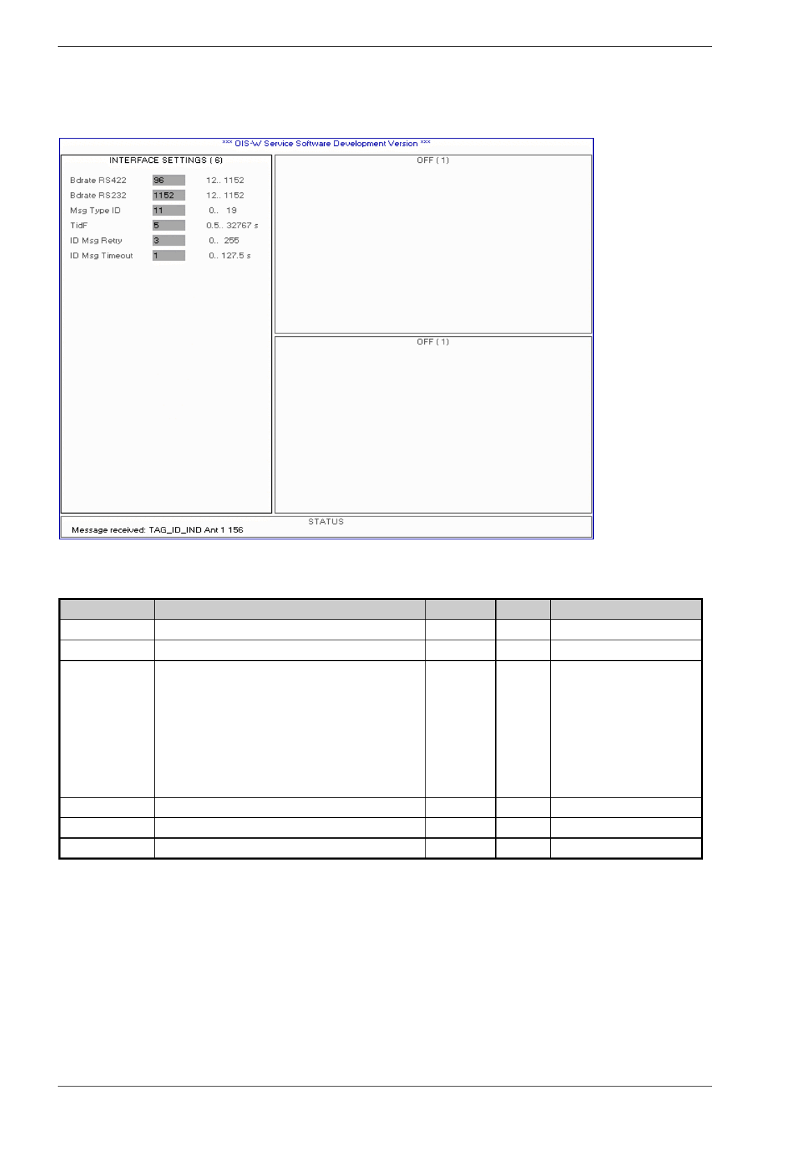
4.1.6 Page 6: Interface Settings
Picture 4-7: interface settings
Term Description Range Default Remarks
Bdrate ID Data Baud rate serial interface RS 422 (R38) 12..1152 1152 9600 baud or 115200 baud
Bdrate Service Baud rate serial interface RS 232 (R13) 12..1152 1152 9600 baud or 115200 baud
Msg Type ID Select type of notification after successful reading 0..19 11 1st digit:
• 0: RS422
• 1: RS232
2nd digit
• 0: OFF
• 1: TAG_ID_IND
• 2: PARAM_DATA
TidF Time constant ID filter (res:.5s) 0.5..32768 1
ID Msg Retry Max. number transmissions of ID Msg (0 = forever) 0..255 3
ID Msg Timeout Time until ID msg is retransmitted (res:0.5s) 0.5..127.5 1
Table 4-7: interface settings
Bdrate RS422 / ID Data
This parameter defines the baud rate of the serial interface RS 422 (R38).
Bdrate RS232 / Service
This parameter defines the baud rate of the serial interface RS 232 (R13).

Baumer Ident AG 25 / 26
Author: Clemens Zehnder File: Maintenance-SW.doc Version 3.0 e
Msg Type ID
This parameter defines the kind of information which is put out via serial interface RS 232 (R13) and serial
interface RS 422 (R38).
• Msg Type ID=01 TAG_ID_IND via serial interface RS 422
• Msg Type ID=11 TAG_ID_IND via serial interface RS 232, default-value
• Msg Type ID=02 Not yet released!
• Msg Type ID=12 Not yet released!
• Msg Type ID=x0 Not yet released!
TidF
This parameter defines in the operation mode „event driven“ the duration after which the same code is put
out again without a different tag (T) having passed the identification point in the meantime.
ID_Msg_Retry
If the receiving end doesn’t acknowledge with a „ACK“ the getting of a telegram from the serial interface
RS 232 (R13) and serial interface RS 422 (R38), the telegram will be resent. The parameter ID Msg Retry
defines the number of repetitions.
ID_Msg_Timeout
This parameter defines the duration between two telegram repetitions.
Baumer Ident AG 26 / 27
Author: Clemens Zehnder File: Maintenance-SW.doc Version 3.0 e
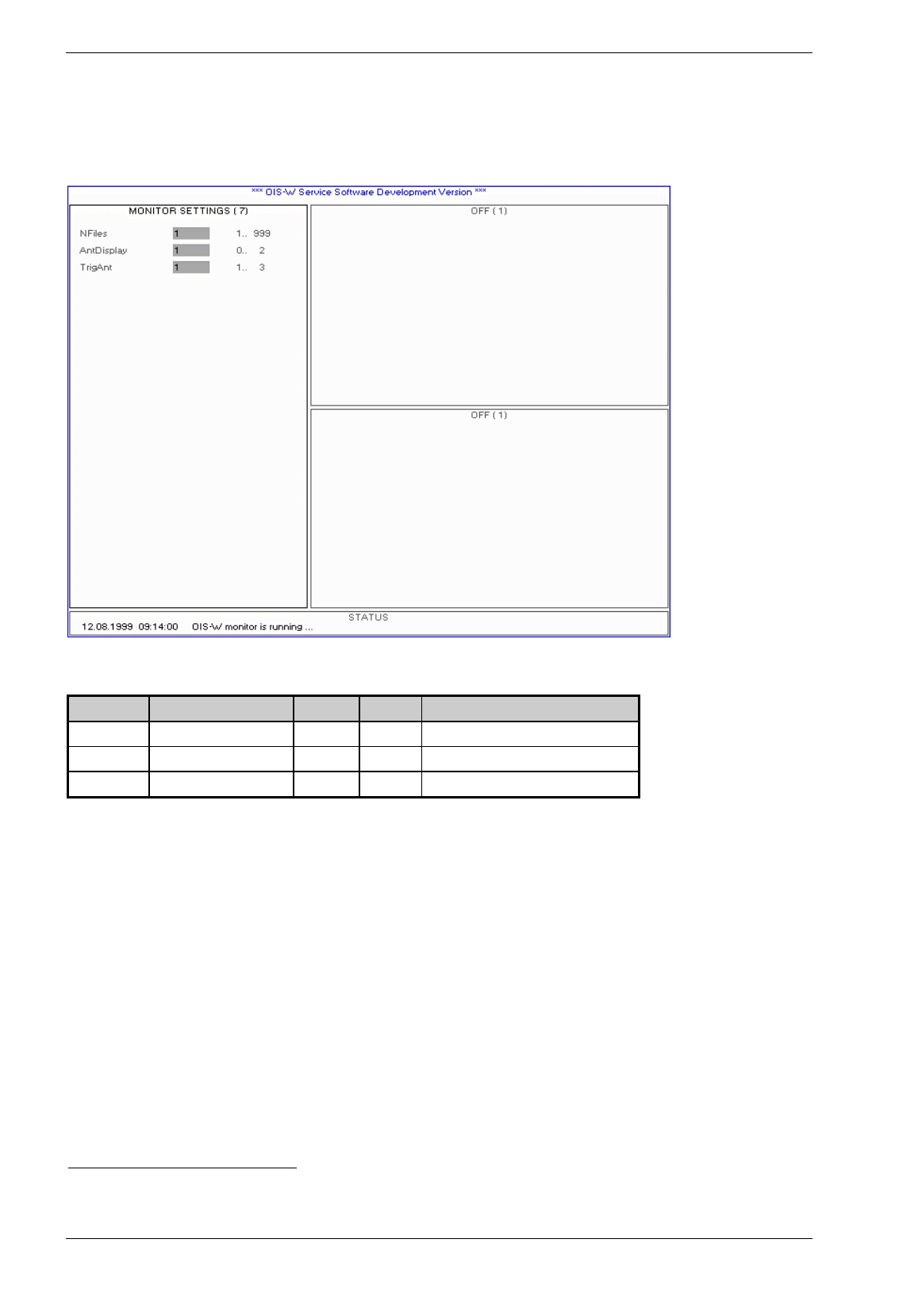
4.1.7 Page 7: Monitor Settings
Picture 4-8: monitor settings
Name Term Range Default Remarks
NFiles Reader data onto disk 1 ... 999 1
AntDisplay Antenna to monitor 0 .. 2 1 0= both Antennas, 1=Ant1, 2=Ant2
TrigAnt Antenna to trigger 1 .. 3 3 1=Ant.1, 2=Ant2, 3=both Antennas
Table 4-8: monitor settings 1
Nfiles
Defines the number of „pictures“ of a current identification situation which will be stored onto disk when
using the function „save reader data onto disk“ (see chapter Remote Diagnostics on page 64).
AntDisplay
Select the antenna (A) which you want to look at with the service PC:
• AntDisplay=0 the data of the antennas 1 and 2 are displayed alternately
• AntDisplay=1 only the data of antenna 1 is displayed
• AntDisplay=2 only the data of antenna 2 is displayed
TrigAnt
Select the antenna (A) which you want to trigger with the help of key „t“ on your service PC.
• TrigAnt=1 only antenna 1 is selected to be triggered
• TrigAnt=2 only antenna 2 is selected to be triggered
• TrigAnt=3 antennas 1 and 2 are selected to be triggered
1 These two parameters are not saved in the reader (R). They are only used in the service PC..
Baumer Ident AG 27 / 28
Author: Clemens Zehnder File: Maintenance-SW.doc Version 3.0 e
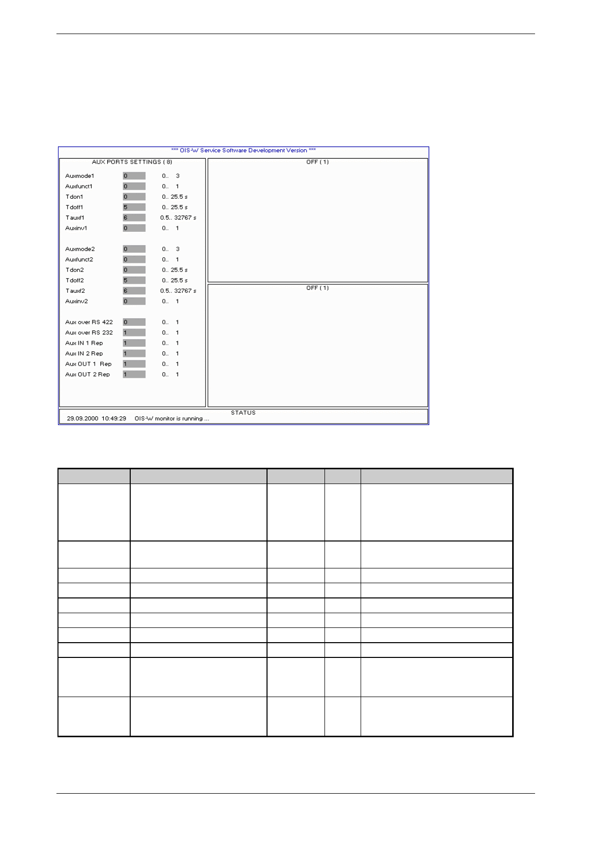
4.1.8 Page 8: Auxiliary Ports Settings
A digital output exits for each antenna. Additional digital outputs are available on binary inputs / outputs 2
(R31)
Picture 4-9: aux ports settings
Name Description Range Default Remarks
Auxmode1 /
Auxmode2
Operation mode of AUX output 0 ... 3 0 0=transparent
1=filtered
2=host triggered
3=ID acknowledge for Ant2
Auxfunct1 /
Auxfunct2
Operation function of AUX output 0 ... 1 1 0=delayed impulse; 1=delayed turn off
Tdon1 / Tdon2 AUX out1 / 2 on delay time 0 ... 25.5 0
Tdoff1 / Tdoff2 AUX out1 / 2 off delay time 0 ... 25.5 0
Tauxf1 / Tauxf2 AUX out1 / 2 on delay time 0.5 ... 32768 0.5
Auxinv1 / Auxinv2 Invert AUX signal 0 ... 1 0 0=off; 1=on
Aux over RS 422 AUX_REP message via RS 422 0 ... 1 0 0=off; 1=on
Aux over RS 232 AUX_REP message via RS 232 0 ... 1 1 0=off; 1=on
Aux IN 1 Rep /
Aux IN 2 Rep
AUX_REP message will be sent
after a state change at Aux IN 1 /
Aux IN 2
0 ... 1 1 0=off; 1=on
Aux OUT 1 Rep /
Aux OUT 2 Rep
AUX_REP message will be sent
after a state change at Aux OUT 1 /
Aux OUT 2
0 ... 1 1 0=off; 1=on
Table 4-9: aux ports settings

Baumer Ident AG 28 / 29
Author: Clemens Zehnder File: Maintenance-SW.doc Version 3.0 e
Advice!
If you want to use the digital outputs, please follow the table 4-10. To set the parameters for the time function in
the chosen operating mode, please follow also the table 4-10. We gladly advise you on defining the parameters
.
Auxmode1 / Auxmode2
There are four ways for the digital output to forward a valid identification:
• Auxmode=0 transparent
• Auxmode=1 filtered
This filter function decides whether the current code N is unequal to the code N-1. In combination with
the time constant Tauxf it is possible to define the duration after which the same code can set the
digital output again without a different tag (T) having passed the identification point in the meantime.
• Auxmode=2 Host triggered
A higher-order system controls the digital output via telegram.
• Auxmode=3 ID acknowledge
If you use only one antenna (Reader settings: Ant=1 or Ant=2) then you have the possibility to indicate
when the host answers the data telegram. The answer telegram is called acknowledge telegram.
Auxfunct1 / Auxfunct2
There are two different timer functions for the digital outputs:
• Auxfunct=0 Impulse
• Auxfunct=1 Delayed turn-off
Tdon1 / Tdon2
This parameter defines the ON delay of the chosen timer function.
Tdoff1 / Tdoff2
This parameter defines the impulse duration (Auxfunct=0) or the OFF delay (Auxfunct=1).
Tauxf1 / Tauxf2
This parameter defines the time constant of the function „Auxmode“.
Auxinv1 / Auxinv2
The output can be inverted.
Ant Auxmode1 Auxmode2
1 1 or 2 3
2 3 1 or 2
Table 4-5: ID acknowledge
Using only Ant1:
When the acknowledge arrives within the duration specified
by the parameter ID_Msg_Timeout, then the digital output
AUX_OUT2 will be „ON“ for the duration specified by the
parameter Tdoff2.
Using only Ant2:
When the acknowledge arrives within the duration specified
by the parameter ID_Msg_Timeout, then the digital output
AUX_OUT1 will be „ON“ for the duration specified by the
parameter Tdoff1.

Baumer Ident AG 29 / 30
Author: Clemens Zehnder File: Maintenance-SW.doc Version 3.0 e
Aux over RS 422
The AUX_REP message will be sent via RS 422 interface.
Aux over RS 232
The AUX_REP message will be sent via RS 232 interface.
Aux IN 1 Rep / Aux IN 2 Rep
This parameter defines if the AUX_REP message will be sent after a state change at Aux IN 1 and/or
Aux IN 2.
Aux OUT 1 Rep / Aux OUT 2 Rep
This parameter defines if the AUX_REP message will be sent after a state change at Aux OUT 1 and/or
Aux OUT 2.
Overview of the operation modes in combination with the timer functions
O
p
eration mode Auxiliar
y
Port Settin
g
s Timer function
Mmain MTxuntr
g
Auxmode Auxfunct Tdon Tdoff Tauxf Auxinv
Event Driven Tx Off
0 0 0 0 0 X1 n.r.2 X Impulse without Aux-Filter
0 0 1 0 0 X X X Impulse with Aux-Filter
0 0 2 0 0 X n.r. X Impulse without Aux-Filter
0 0 0 1 0 X n.r. X Dela
y
ed turn-off without Aux-Filter
0 0 1 1 0 X X X Dela
y
ed turn-off with Aux-Filter
0 0 0 0 X
>0 n.r. X Dela
y
ed impulse without Aux-Filter
0 0 1 0 X
>0 X X Dela
y
ed impulse with Aux-Filter
Event Driven Tx On
0 1 0 0 0 X n.r. X Impulse without Aux-Filter
0 1 1 0 0 X X X Impulse with Aux-Filter
0 1 2 0 0 X n.r. X Impulse without Aux-Filter
0 1 0 1 0 X n.r. X Dela
y
ed turn-off without Aux-Filter
0 1 1 1 0 X X X Dela
y
ed turn-off with Aux-Filter
0 1 0 0 X
>0 n.r. X Dela
y
ed impulse without Aux-Filter
0 1 1 0 X
>0 X X Dela
y
ed impulse with Aux-Filter
Triggered Tx Off
1 0 0 0 0 X n.r. X Impulse without Aux-Filter
1 0 2 0 0 X n.r. X Impulse without Aux-Filter
1 0 0 0 X
>0 n.r. X Dela
y
ed impulse without Aux-Filter
Triggered Tx On
1 1 0 0 0 X n.r. X Impulse without Aux-Filter
1 1 2 0 0 X n.r. X Impulse without Aux-Filter
1 1 0 0 X
>0 n.r. X Delayed impulse without Aux-Filter
Table 4-10: overview of the operation modes in combination with the timer functions
Please note: Combination „Auxmode=2 (Host triggered) with Delayed turn off“ doesn’t make any sense.
1 X: value according to the definition of the range of the respective parameter
2 n.r. : not relevant in this combination
Baumer Ident AG 30 / 31
Author: Clemens Zehnder File: Maintenance-SW.doc Version 3.0 e
4.2 Window 2
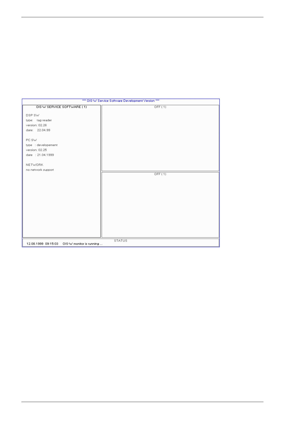
4.2.1 Page 1: OFF
This page doesn’t have any meaning for the user.
Picture 4-10: off
Baumer Ident AG 31 / 32
Author: Clemens Zehnder File: Maintenance-SW.doc Version 3.0 e
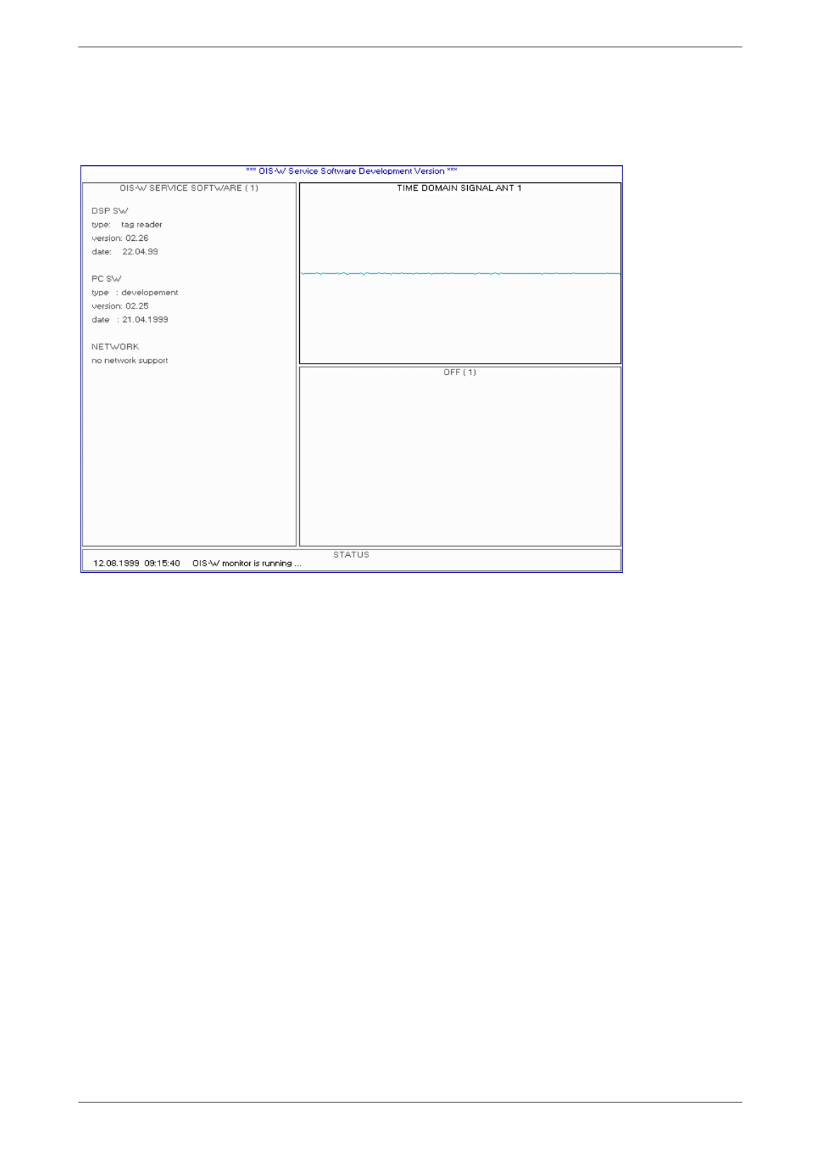
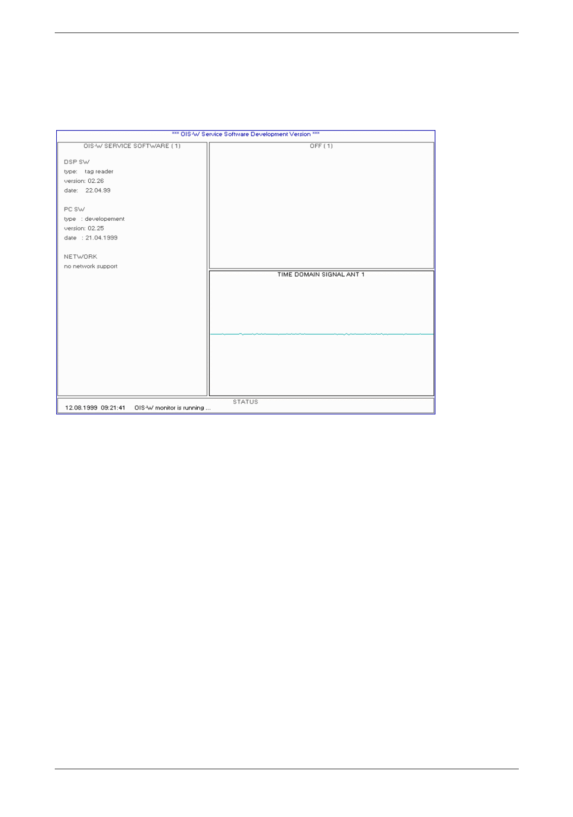
4.2.2 Page 2: Time Domain Signal
Picture 4-11: time domain signal
Tome Domain Signal
This diagram indicates the time domain signal after the A/D converter. It is the response signal in the
audio band which has been mixed down with the help of a local oscillator and filtered. The diagram shows
the whole range of the A/D converter. The duration is 16 ms and the resolution 8 Bits.
This diagram is for experienced users only.
Baumer Ident AG 32 / 33
Author: Clemens Zehnder File: Maintenance-SW.doc Version 3.0 e
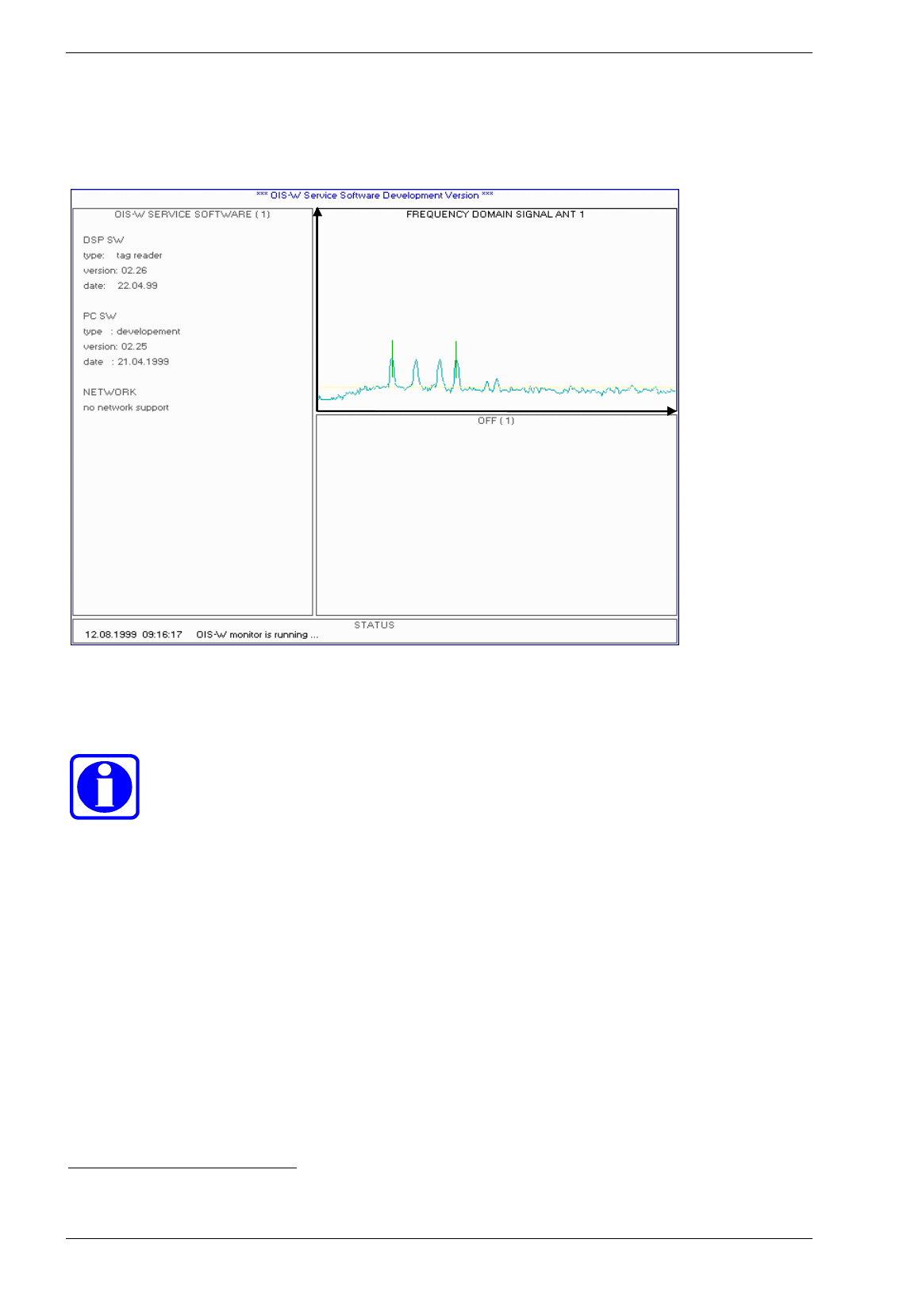
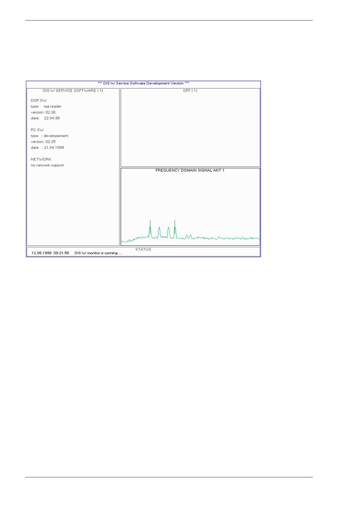
4.2.3 Page 3: Frequency Domain Signal
50
0n
s
42
50
ns
0dB
128dB
Picture 4-12: frequency domain signal
Advice!
Use this diagram to assess the signal of the tag and the noise of the environment.
Frequency Domain Signal
The diagram indicates the frequency domain signal after the FFT1. Frequencies between 1.25 kHz and
10.625 kHz are shown. These frequencies correspond to a propagation delay time of the response signal
from 500 ns up to 4250 ns.
The length of the y-axle corresponds to 128 dB (8 bit resolution).
The diagram shows on the left a calibrator amplitude and then three signal amplitudes.
The left of the two vertical marks, which are defined by the parameters InitDelay and DelayRange, is at
the calibrator amplitude and the right at the last signal amplitude. The range within which the noise for the
S/N ratio is measured is marked in red.
Please note the practical example on page 59.
1 Fast Fourier Tranformation
Baumer Ident AG 33 / 34
Author: Clemens Zehnder File: Maintenance-SW.doc Version 3.0 e
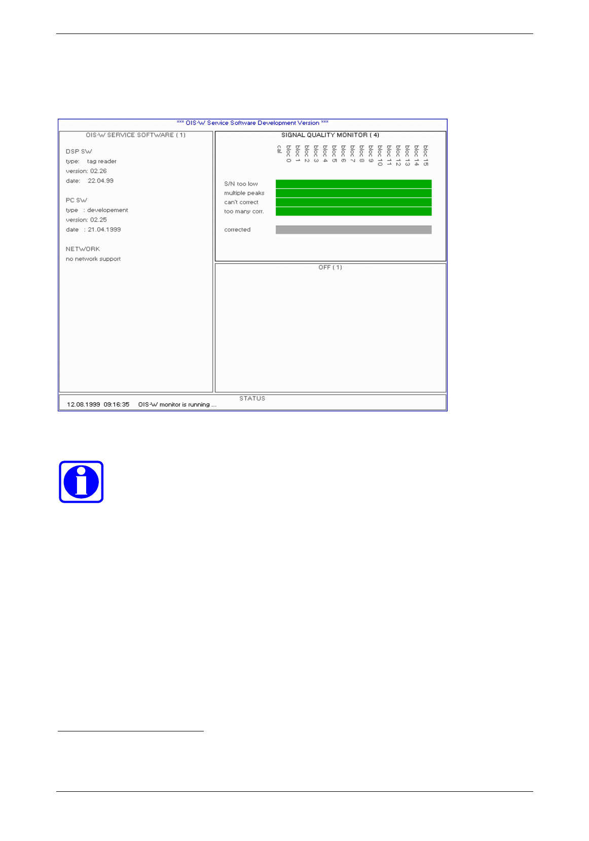
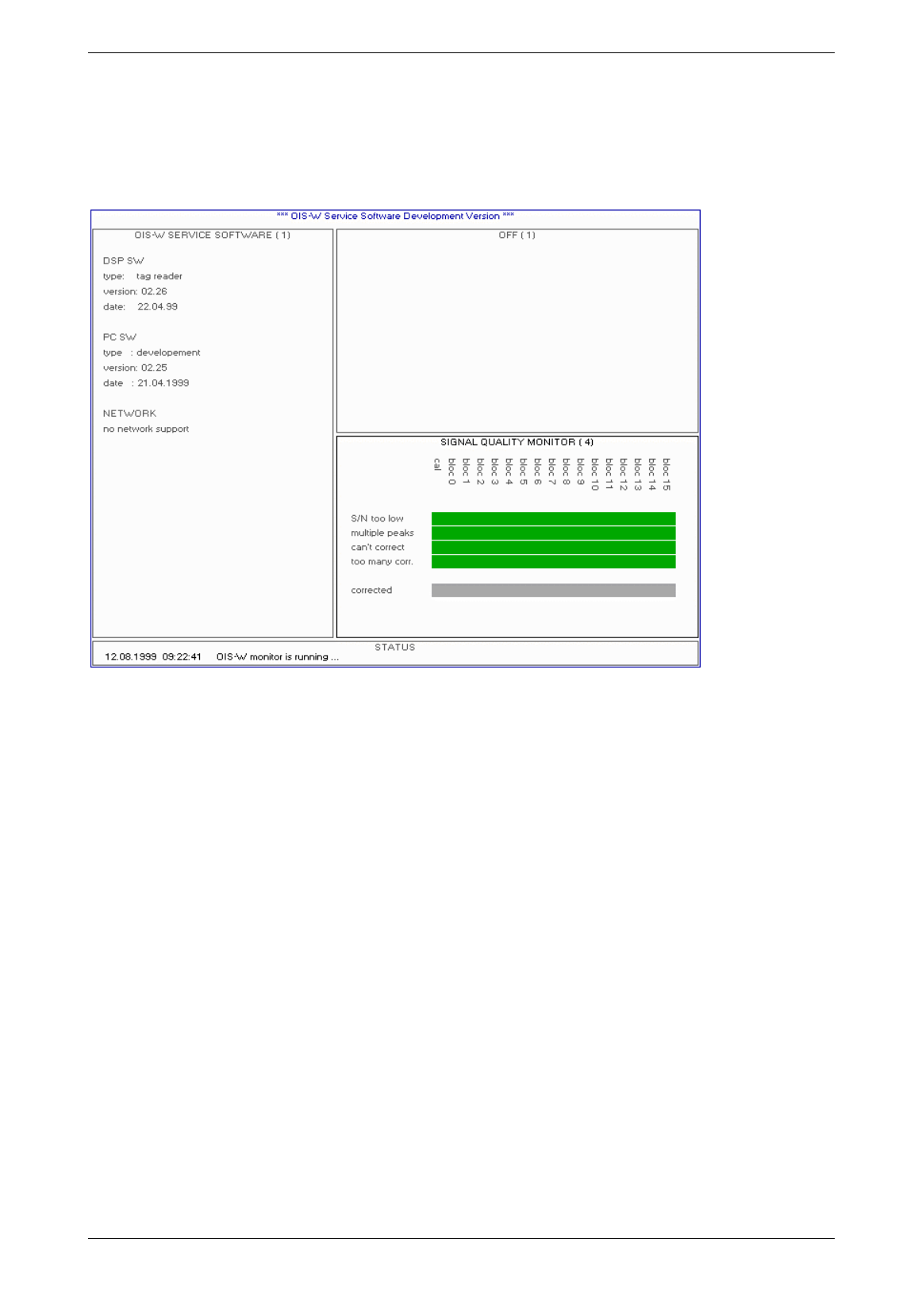
4.2.4 Page 4: Signal Quality Monitor
Picture 4-13: signal quality monitor
Advice!
Use the signal quality monitor to assess which bits of the code are interfered.
The blocks stand for the several digits of the code.
S/N too low
If the flag shines green the measured S/N ratio is higher than or equal to the defined threshold SNR1.
Otherwise the flag shines red.
Multiple peaks
If the flag shines green the signal peak is strong enough with reference to noise peaks possibly located in
the same block.
Otherwise the flag shines red.
PSignal ≥ PNoise + DMultiTag2
Can’t correct / Too many corrections / Corrected
Only for DSP SW test purposes!
1 Parameter „Reader Settings: SNR
2 Parameter „Reader Settings: DMultiTag
Baumer Ident AG 34 / 35
Author: Clemens Zehnder File: Maintenance-SW.doc Version 3.0 e
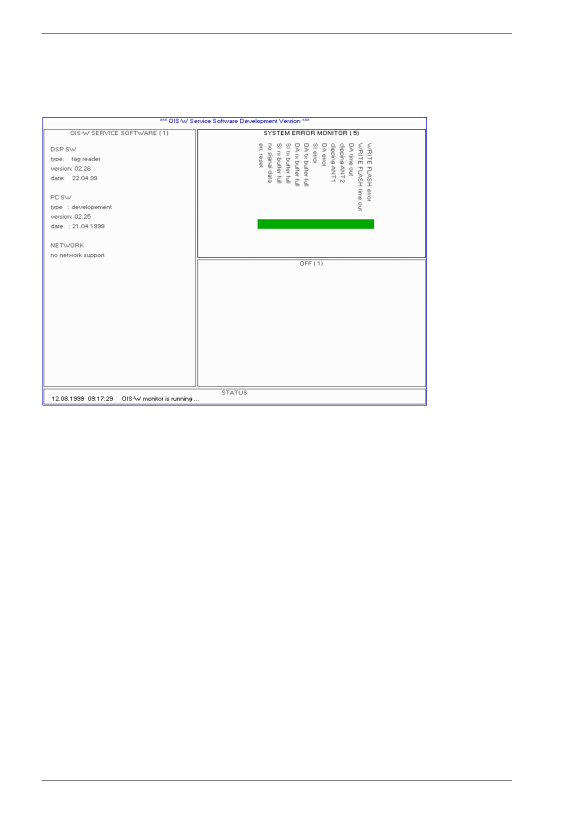
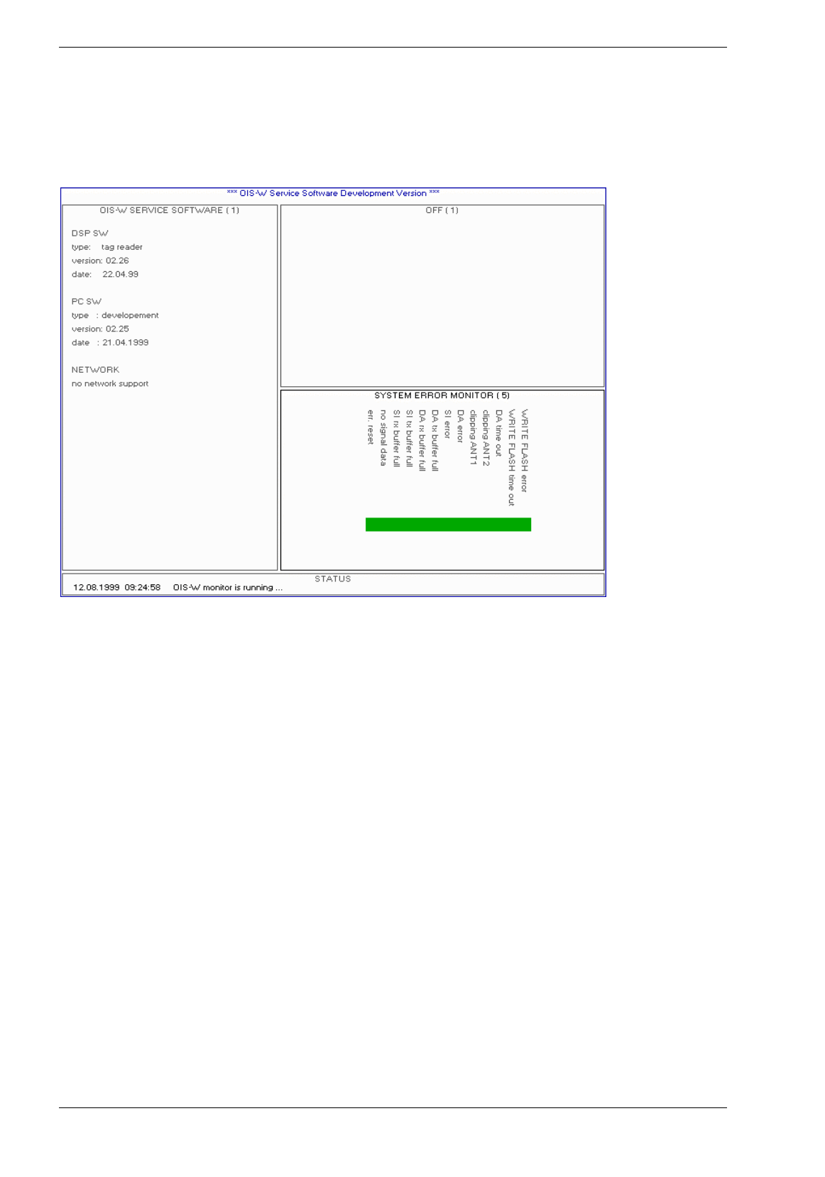
4.2.5 Page 5: System Error Monitor
Picture 4-14: system error monitor
Error Reset
This flag doesn’t have any meaning for the user.
No Signal Data
This flag shines red if the reader (R) doesn’t receive a sufficiently strong signal from a tag (T).
Otherwise the flag shines green.
SI Rx Buffer full
This flag shines red if the receiving buffer of the serial interface RS 232 (R13) is filled.
SI Tx Buffer full
This flag shines red if the sending buffer of the serial interface RS 232 (R13) is filled.
DA Rx Buffer full
This flag shines red if the receiving buffer of the serial interface RS 422 (R38) is filled.
DA Tx Buffer full
This flag shines red if the sending buffer of the serial interface RS 422 (R38) is filled.
SI Error
This flag shines red if an internal error has happened. Normally the user doesn’t have the possibility to fix
this.

Baumer Ident AG 35 / 36
Author: Clemens Zehnder File: Maintenance-SW.doc Version 3.0 e
DA Error
Not yet released!
Clipping Ant 1
This flag shines red if the receiver channel of the antenna 1 is overdriven
Clipping Ant 2
This flag shines red if the receiver channel of the antenna 2 is overdriven.
DA Time Out
This flag shines red if the receiving end of the serial interface RS 232 (R13) or the serial interface RS 422
(R38) doesn’t acknowledge within the duration defined with the parameters ID_Msg_Retry1 and
ID_Msg_Timeout2.
Write Flash error
This flag shines red if an internal reader error in the flash memory has happened.
Write Flash time out
This flag shines red if a undefined time delay is caused during downloading SW (DSP-SW, FPGA-SW).
1 Parameter „Interface Settings: ID Msg Retry“
2 Parameter „Interface Settings: ID Msg Timeout“
Baumer Ident AG 36 / 37
Author: Clemens Zehnder File: Maintenance-SW.doc Version 3.0 e
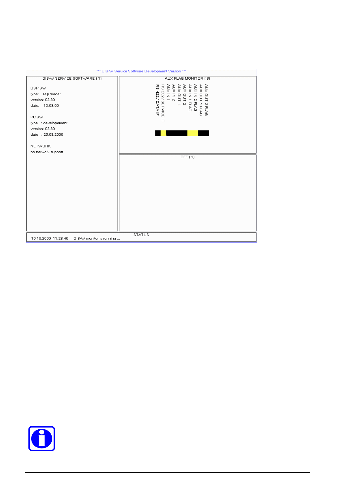
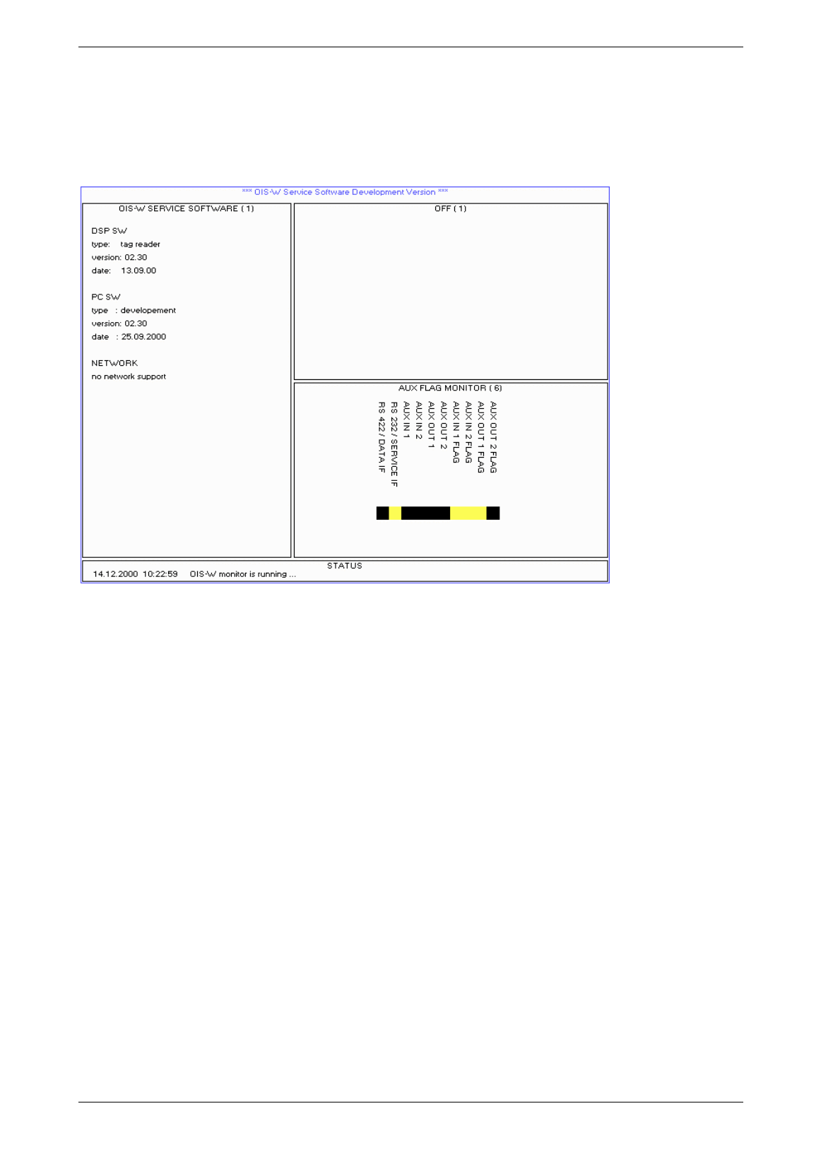
4.2.6 Page 6: Aux Flag Monitor
Picture 4-15: aux flag monitor
RS 422 / DATA IF
This flag shines yellow if the AUX_REP message will be sent via RS 422 interface.
RS 232 / SERVICE IF
This flag shines yellow if the AUX_REP message will be sent via RS 232 interface.
Aux IN 1 / Aux IN 2
This flag shines yellow during a logical “1” at Aux IN 1 / Aux IN 2.
Aux OUT 1 / Aux OUT 2
This flag shines yellow during a logical “1” at Aux OUT 1 / Aux OUT 2.
Aux IN 1 FLAG / Aux IN 2 FLAG
This flag shines yellow after a state change at Aux IN 1 / Aux IN 2.
Aux OUT 1 FLAG / Aux OUT 2 FLAG
This flag shines yellow after a state change at Aux OUT 1 / Aux OUT 2.
Advice!
The flag information (Aux IN 1 FLAG, Aux IN 2 FLAG, Aux OUT 1 FLAG, Aux OUT 2 FLAG)
will only be reset after a MSG_ACK or a SET_AUX_CONFIG_REQ message.
Baumer Ident AG 37 / 38
Author: Clemens Zehnder File: Maintenance-SW.doc Version 3.0 e
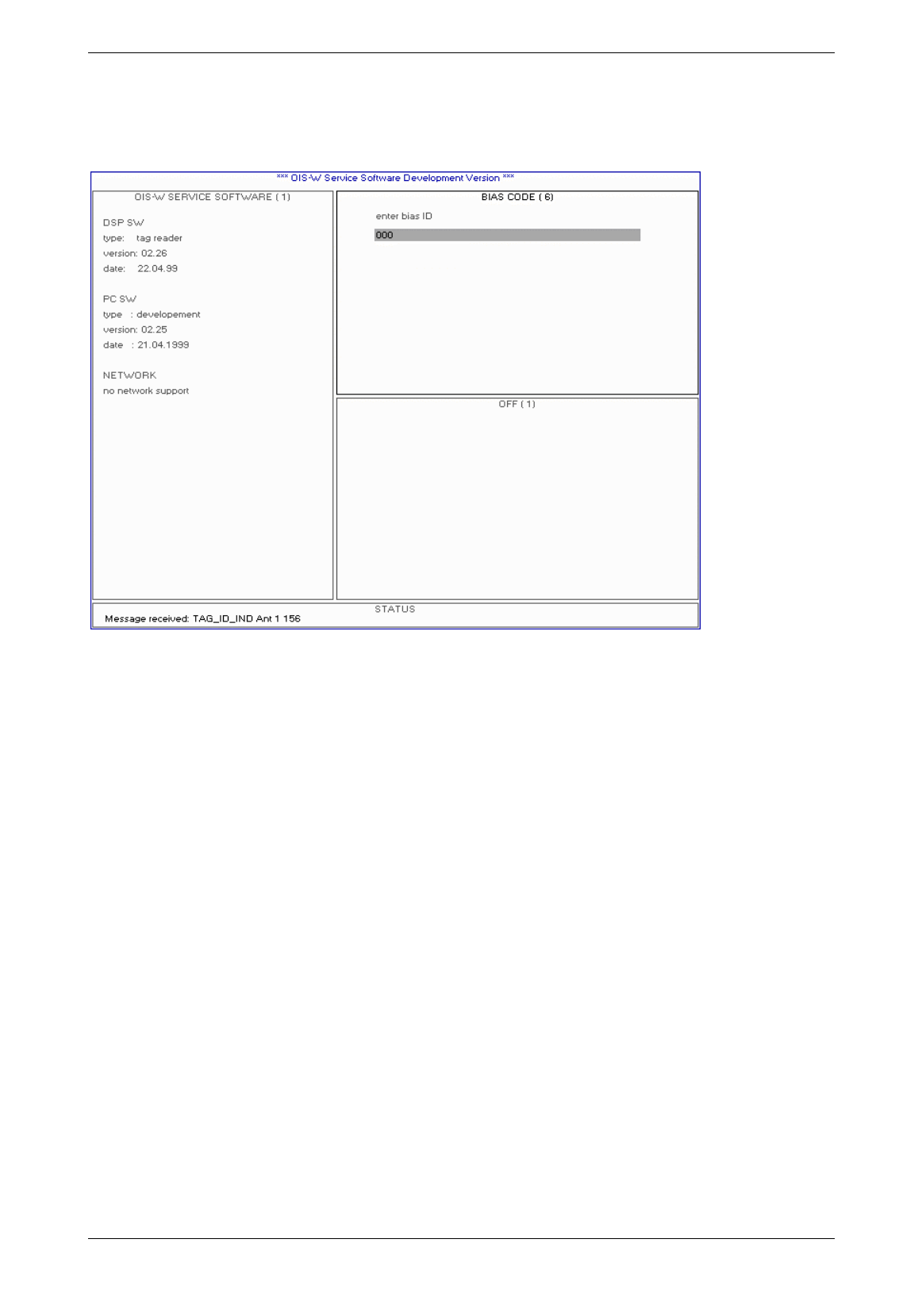
4.2.7 Page 7: Bias Code
Not yet released!
Picture 4-16: bias code
Baumer Ident AG 38 / 39
Author: Clemens Zehnder File: Maintenance-SW.doc Version 3.0 e
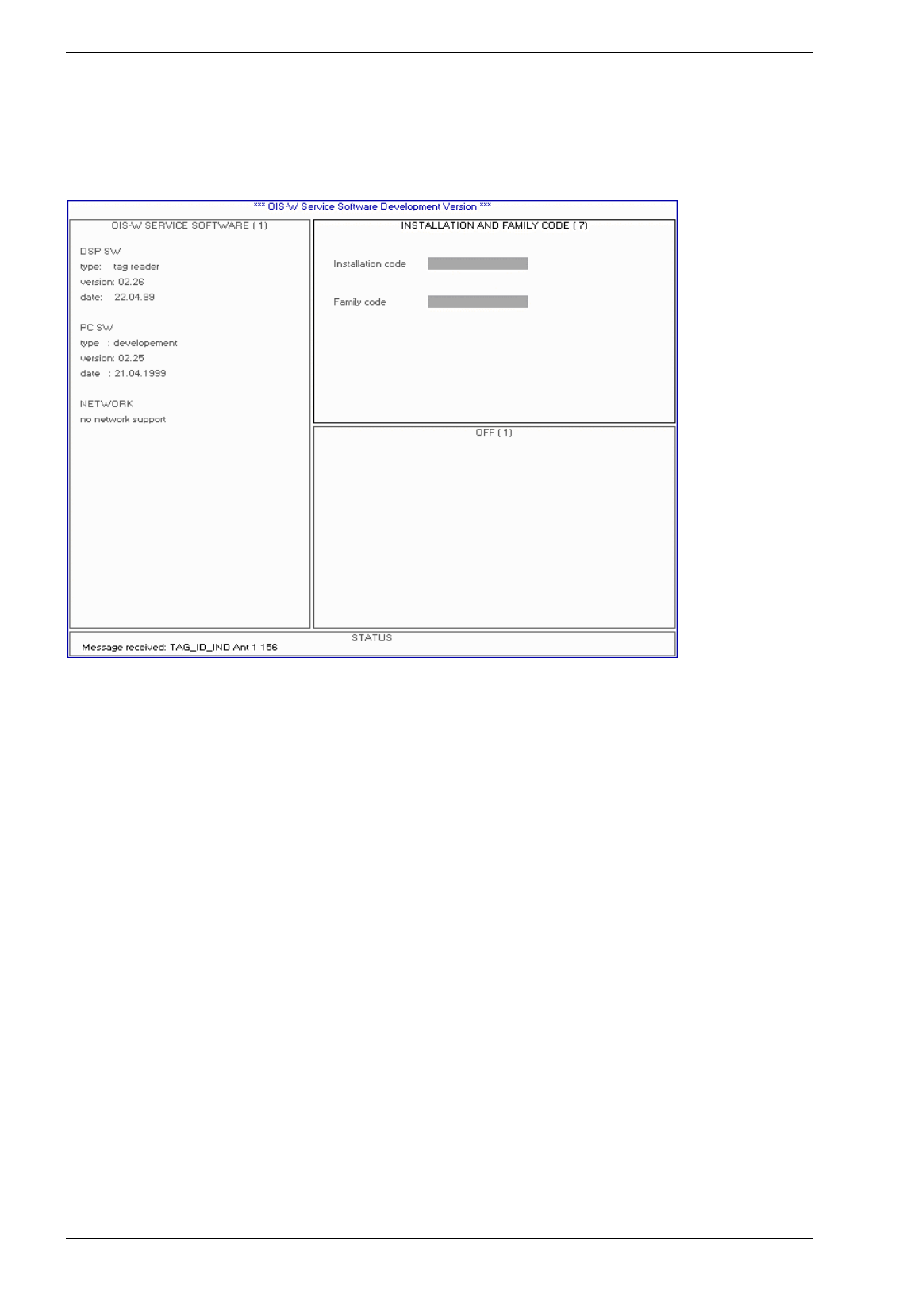
4.2.8 Page 8: Installation and Family Code
Not in operation!
Picture 4-17: installation and family code
Baumer Ident AG 39 / 40
Author: Clemens Zehnder File: Maintenance-SW.doc Version 3.0 e
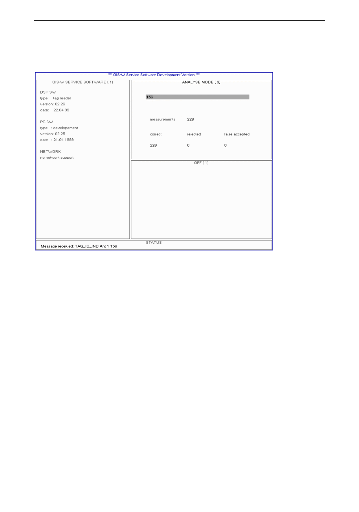
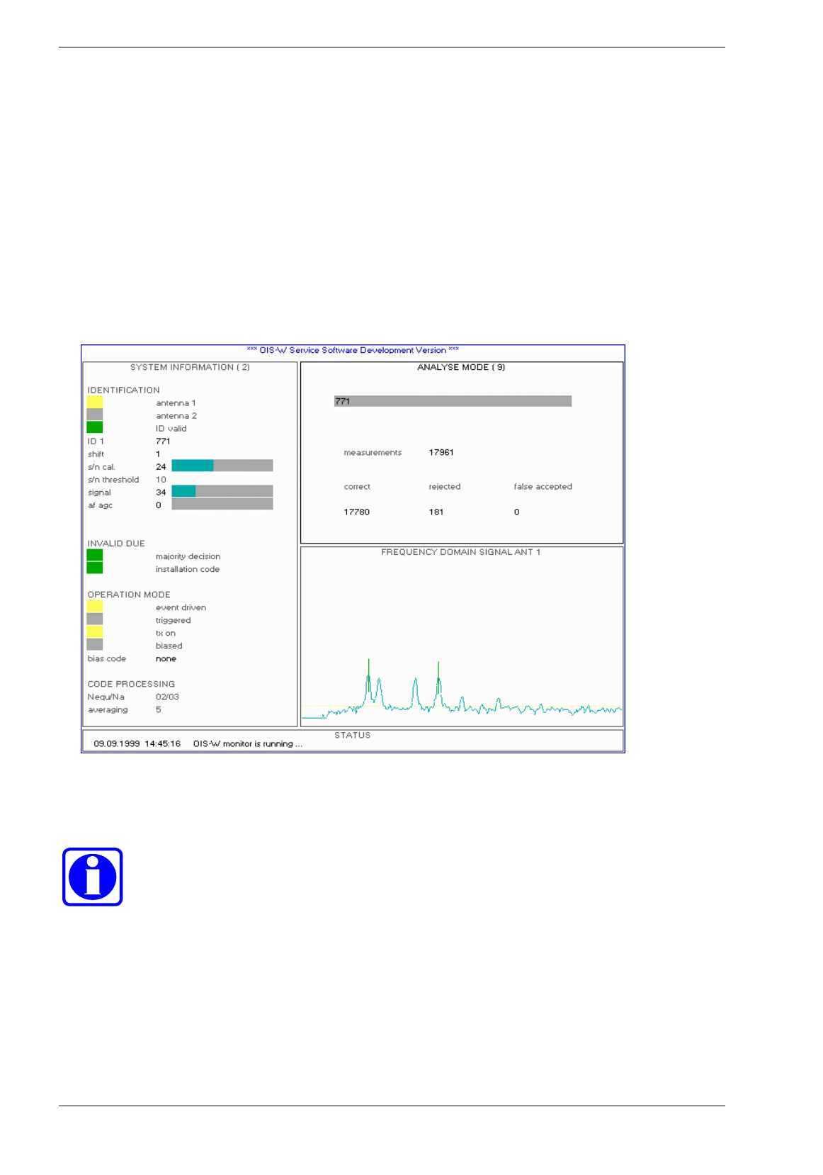
4.2.9 Page 9: Analyze Mode
Picture 4-18: analyze mode
Analyse Mode
You can test the reliability of an identification by using the analyse mode. Enter the expected code and put
the tag into the reading area of the antenna. Use only one code for this test. The system will indicate:
• measurements
Number of measurements
• correct
Number of correct codes. The codes, which the system has accepted, are equal to the reference code
which you have entered.
• rejected
The reading conditions are not fulfilled.
• falsely accepted
Number of falsely accepted codes. The codes, which the system has accepted, are not equal to the
reference code which you have entered.
Baumer Ident AG 40 / 41
Author: Clemens Zehnder File: Maintenance-SW.doc Version 3.0 e
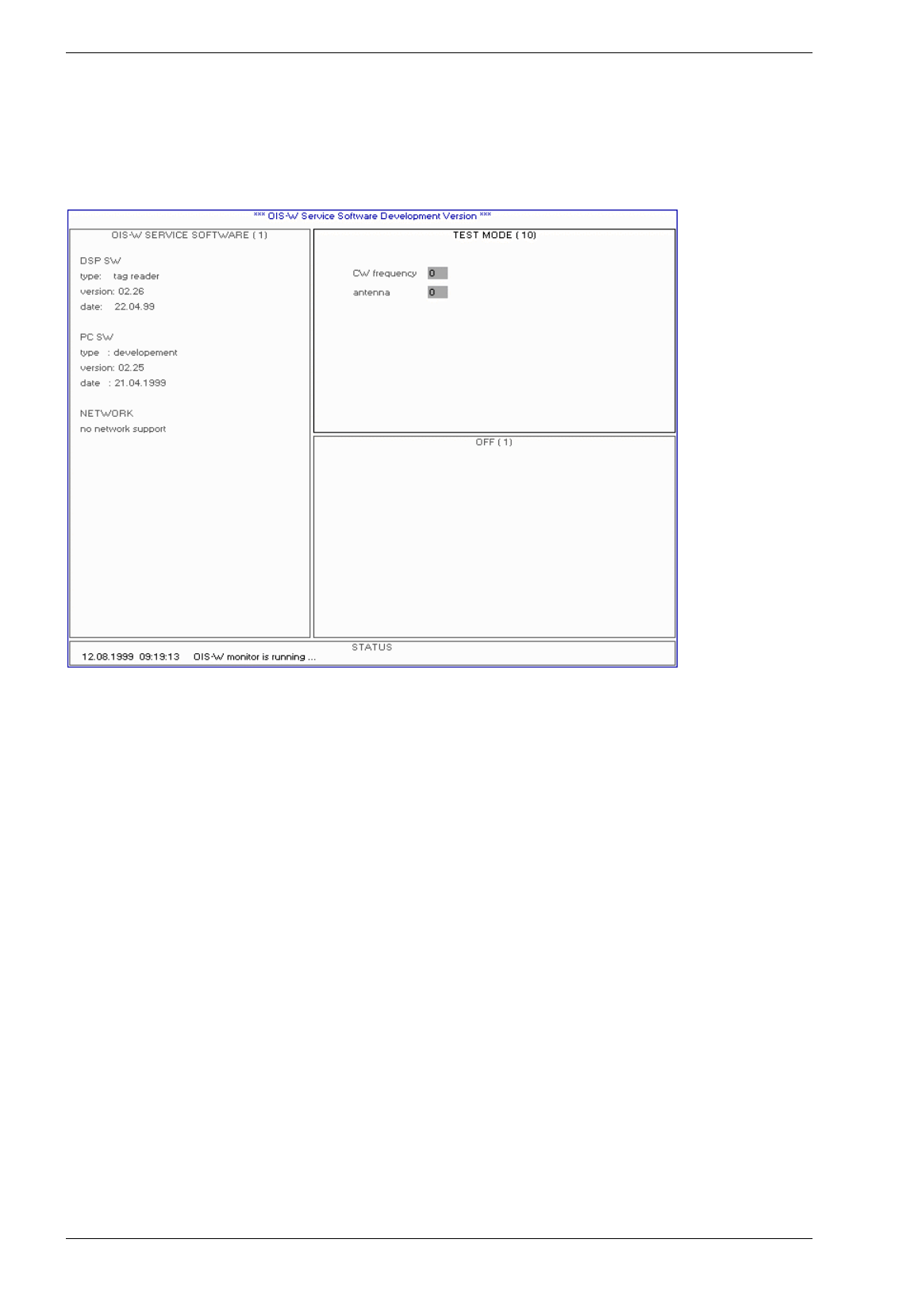
4.2.10 Page 10: Test Mode
Only for hardware test!
Picture 4-19: test mode
Baumer Ident AG 41 / 42
Author: Clemens Zehnder File: Maintenance-SW.doc Version 3.0 e
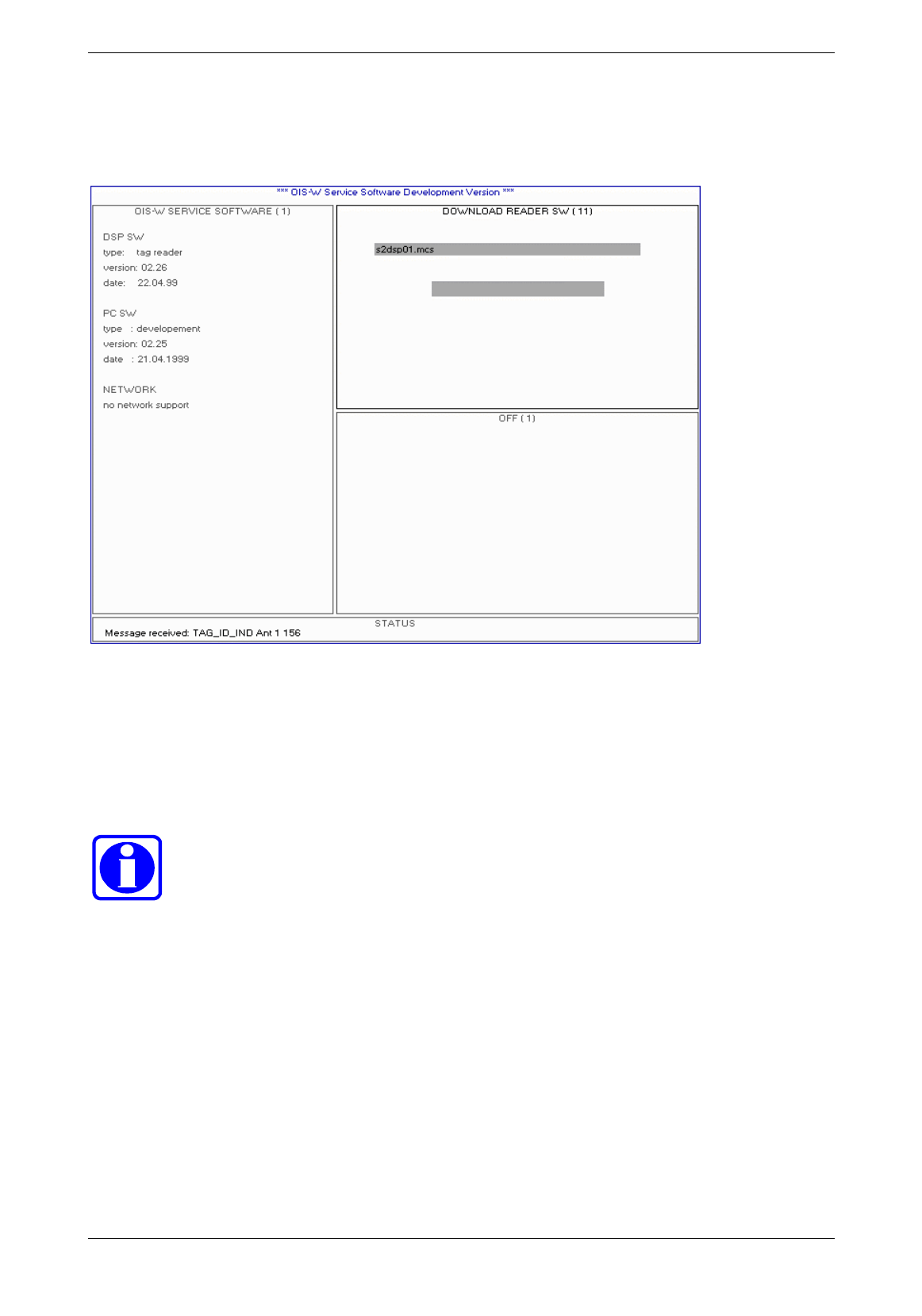
4.2.11 Page 11: Download Reader SW
Picture 4-20: download reader SW
Download Reader SW
The user has the possibility to update the DSP-SW in the reader (R) with the help of this input mask. The
bar graph indicates the progress of the download.
Advice!
If you need a DSP-SW update for any reason, please use this function to download the
update supplied by Baumer Ident.

Baumer Ident AG 42 / 43
Author: Clemens Zehnder File: Maintenance-SW.doc Version 3.0 e
4.2.12 Page 12: Download FPGA SW
Picture 4-21: download FPGA SW
Download FPGA SW
The user has the possibility to update the FPGA-SW in the reader (R) with the help of this input mask.
The bar graph indicates the progress of the download.
Baumer Ident AG 43 / 44
Author: Clemens Zehnder File: Maintenance-SW.doc Version 3.0 e
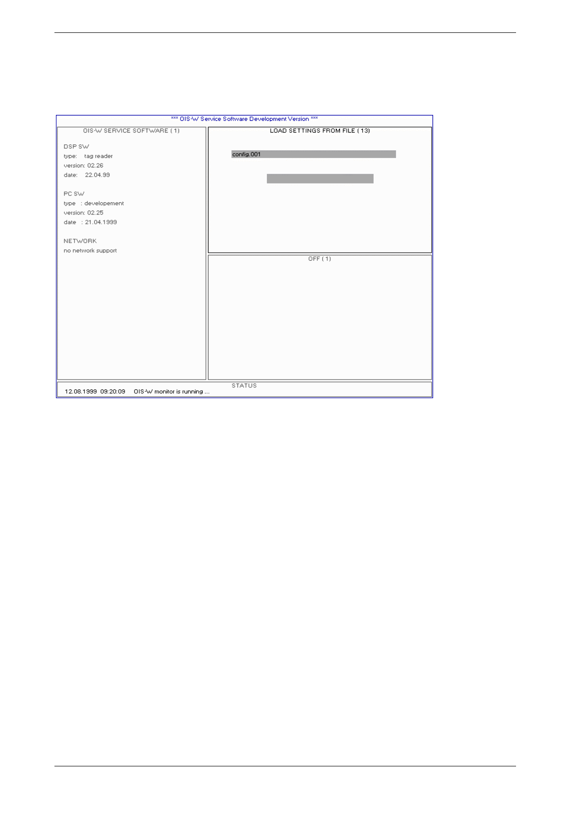
4.2.13 Page 13: Load Settings from File
Picture 4-22: load settings from file
Load Settings to File
The configuration file can be stored onto the harddisk of your service PC. The user can download the file
from your working directory into the reader with the help of this input mask.
Baumer Ident AG 44 / 45
Author: Clemens Zehnder File: Maintenance-SW.doc Version 3.0 e
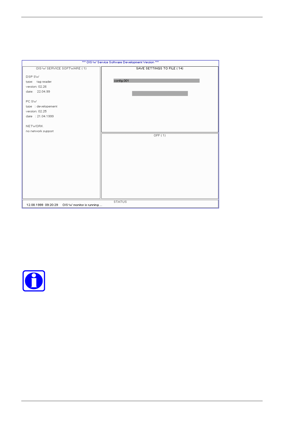
4.2.14 Page 14: Save Settings to File
Picture 4-23: save settings to file
Save Settings to File
The configuration file is stored in the reader (R). The user can rename and save it into the working
directory of the service PC with the help of this input mask.
Advice!
If you have any problems with the system, please save the configuration file and send it to
us.

Baumer Ident AG 45 / 46
Author: Clemens Zehnder File: Maintenance-SW.doc Version 3.0 e
4.2.15 Page 15: Load Code Table from File
Picture 4-24: load code table from file
Load Code Table from File
The tag (T) contains a fix code per definition. The linking of the fix code with an application specific
identification number can be carried out within the reader (R) with the help of a look up table.
This function allows downloading of the look up table (also called code table) from the working directory of
your service PC into the reader (R).
See also parameter „Entab“ on page 22.
Baumer Ident AG 46 / 47
Author: Clemens Zehnder File: Maintenance-SW.doc Version 3.0 e
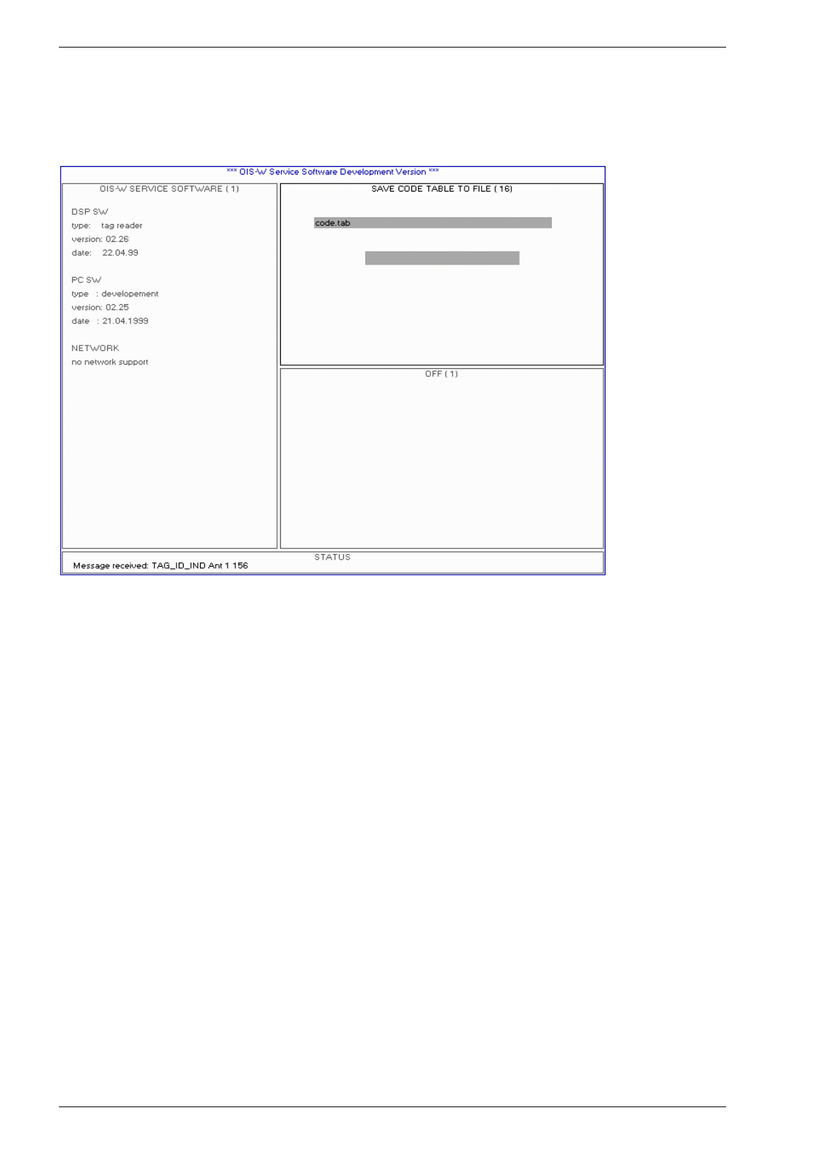
4.2.16 Page 16: Save Code Table to File
Picture 4-25: save code table to file
Save Code Table to File
The tag (T) contains a fix code per definition. The linking of the fix code with an application specific
identification number can be carried out within the reader (R) with the help of a look up table.
This function allows downloading of the look up table (also called code table) from the reader (R) into the
working directory of your service PC .
See also parameter „Entab“ on page 22.
Baumer Ident AG 47 / 48
Author: Clemens Zehnder File: Maintenance-SW.doc Version 3.0 e
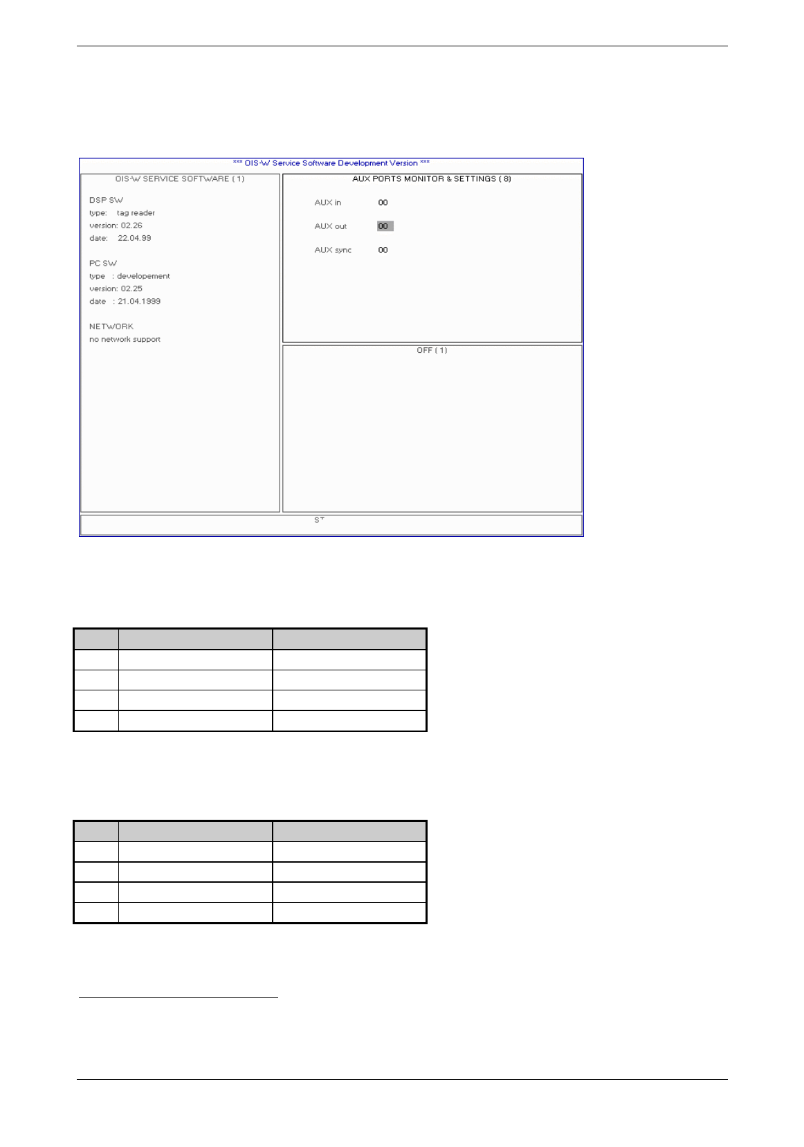
4.2.17 Page 17: Aux Ports Monitor and Settings
Use these functions only for tests.
Picture 4-26: aux ports and settings
Aux In
Aux In is an output mask. It indicates the status of the digital inputs.
Value Digital input antenna 11 Digital input antenna 2
00 „0“ „0“
01 „1“ „0“
02 „0“ „1“
03 „1“ „1“
Table 4-11: definition Aux In
Aux Out
Aux Out is an input mask. The two digital outputs can be set and reset.
Value Digital output antenna 12 Digital output antenna 2
00 „0“ „0“
01 „1“ „0“
02 „0“ „1“
03 „1“ „1“
Table 4-12: definition Aux Out
1 Binary Inputs / Outputs 1 (R39)
2 Binary Inputs / Outputs 1 (R39)
Baumer Ident AG 48 / 49
Author: Clemens Zehnder File: Maintenance-SW.doc Version 3.0 e
4.3 Window 3
All pages of window 3 are also contained in window 2. Due to this fact the user can design his own
graphical interface by selecting the respective page of each window.
4.3.1 Page1: OFF
This page doesn’t have any meaning for the user.
Picture 4-27. off
Baumer Ident AG 49 / 50
Author: Clemens Zehnder File: Maintenance-SW.doc Version 3.0 e
4.3.2 Page 2: Time Domain Signal
This page is identical with page 2 in window 2 on page 31.
Picture 4-28: time domain signal
Baumer Ident AG 50 / 51
Author: Clemens Zehnder File: Maintenance-SW.doc Version 3.0 e
4.3.3 Page 3: Frequency Domain Signal
This page is identical with page 3 in window 2 on page 32.
Picture 4-29: frequency domain signal
Baumer Ident AG 51 / 52
Author: Clemens Zehnder File: Maintenance-SW.doc Version 3.0 e
4.3.4 Page 4: Signal Quality Monitor
This page is identical with page 4 in window 4 on page 33.
Picture 4-30: signal quality monitor
Baumer Ident AG 52 / 53
Author: Clemens Zehnder File: Maintenance-SW.doc Version 3.0 e
4.3.5 Page 5: System Error Monitor
This page is identical with page 5 in window 2 on page 34.
Picture 4-31: system error monitor
Baumer Ident AG 53 / 54
Author: Clemens Zehnder File: Maintenance-SW.doc Version 3.0 e
4.3.6 Page 5: Aux Flag Monitor
This page is identical with page 6 in window 2 on page 36.
Picture 4-32: aux flag monitor
Baumer Ident AG 54 / 55
Author: Clemens Zehnder File: Maintenance-SW.doc Version 3.0 e
5 How to put into Practice
5.1 Logistics
5.1.1 The following Components have been used
Abb. Terms Reference-Code
R Reader WR-xxxx
T Tag WT-xx1x
A Antenna WA-xxxx
C Rf cable WC-0050
S Service Software WS-0210
Table 5-1: components of the application logistics
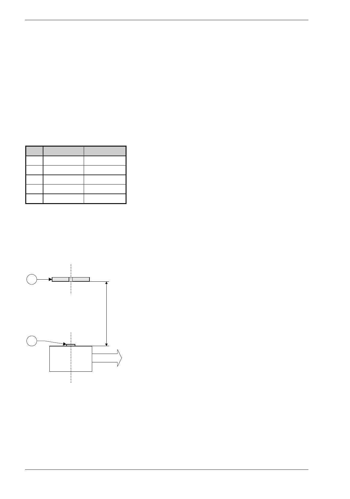
5.1.2 Instructions for the Application
A tag (T) is fixed at an object and passes the antenna (A) at a defined distance and at a defined maximum
speed. Tag (T) and antenna (A) are on the same plane and their surface normals are parallel.
V=0.5 m/s
1.0 m
A
T
Picture 5-1: application logistics; top view

Baumer Ident AG 55 / 56
Author: Clemens Zehnder File: Maintenance-SW.doc Version 3.0 e
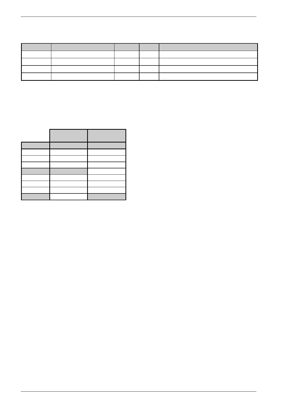
5.1.3 Table of the Parameters of Configuration
Name Logistics
•
one Antenna
• Triggered Mode 1
Logistics
• one Antenna
• Event Driven Mode
Tag Structure Settings
Tslot 2 2
Ncodebloc 3 3
Ncodeslot 11 11
Ncalrefl 1 1
Ncoderef 1 1
Ncheckrefl 0 0
Nextrefl 0 0
Nmesrefl 0 0
Tcode00 104 104
Tcal -8 -8
Tmes0 220 220
Puseguard 1 1
Operation Mode Settings
MMain 1 0
MTxuntrig 1 1
MBiased 0 0
MRandom 0 0
MRTm 50 50
MRNmess 1 1
MRTdmin 1 1
MRTdlen 1 1
MTsleep 1 1
Reader Settings
InitDelay1 5 5
DelayRange1 5 5
InitDelay2 5 5
DelayRange2 5 5
Ant 1 1
Channel 15 15
AFAGC 0 0
Nnoisebin 15 15
SNR 10 10
DSNRCal 1 1
DMultiTag 5 5
Navg 5 5
Nequ 2 2
1 You can trigger with the help of the key „t“ for test purposes (you don’t have to connect the digital inputs)

Baumer Ident AG 56 / 57
Author: Clemens Zehnder File: Maintenance-SW.doc Version 3.0 e
Name Logistics Logistics
Na 3 3
Ntab 0 0
Pposuser 0 0
Nuser 0 0
Interface Settings
BdrateRS422 96 96
BdrateRS232 1152 1152
Msg Type ID 11 11
TidF 5 5
ID Msg Retry 3 3
ID Msg Timeout 1 1
Monitor Settings
NFiles 1 1
AntDisplay 1 1
TrigAnt 1 1
Aux Ports Settings
Auxmode1 0 0
Auxfunct1 0 0
Tdon1 0 0
Tdoff1 0.5 0.5
Tauxf1 0.5 0.5
Auxinv1 0 0
Auxmode2 0 0
Auxfunct2 0 0
Tdon2 0 0
Tdoff2 0.5 0.5
Tauxf2 0.5 0.5
Auxinv2 0 0
Table 5-2: configuration parameter
Advice!
The parameter monitor settings "AntDisplay" and "TrigAnt" are not saved in the reader.
After a restart of the service software these parameters have to be newly inserted.
1 You can trigger with the help of the key „t“ for test purposes (you don’t have to connect the digital inputs)

Baumer Ident AG 57 / 58
Author: Clemens Zehnder File: Maintenance-SW.doc Version 3.0 e
5.1.4 Setup of the InterBus-S (only for WR-1x1x)
The InterBus-S configurations are listed below. Customer specific applications are available.
• The reader logs on as a simple input device with the ID-Code 0x02.
• The data bus width is defined as 1 word (16 bit).
• The coding of the normal codes is handled with packed BCD, i.e. 4 bit per
position for the digits 0...9, 4 positions (0000...9999).
• Messages, which don’t contain any codes, are labeled with a hexadecimal number higher than 9 in the
very highest position. The lowest three BCD-positions contain a respective message code.
• In the initial state the reader (R) sends out the message 0xF000 (READY).
• After the tag (T) has been triggered by an external signal it sends out for one time the identified code
or the message 0xF001 (NO_READ).
After the next InterBus-S cycle it once sends out the READY-Signal one time only until the next trigger
arrives.
Baumer Ident AG 58 / 59
Author: Clemens Zehnder File: Maintenance-SW.doc Version 3.0 e
5.1.5 Learning by doing
Please carry out the application „Logistics“. Follow the steps below:
1. Connect the hardware components and switch on the reader (R) as described in the user’s manual
„2.45 GHz Ident System Hardware“.
2. Install the Service Software Basic (S01 as described in chapter 2!
3. Build up the test arrangement as described in chapter 5.1.2!
4. Put in the configuration parameter as described in chapter 5.1.3!
5. Press the key „F5“!
6. If all the steps have been carried out successfully you will see the following picture on the screen of the
service PC:
Picture 5-2: successful identification supplied by the Service Software Basic (S01)
Advice!
One standard combination of the pages of the service software is stored under the key
"F5". Feel free to change this set-up in file "OISW.INI".
Baumer Ident AG 59 / 60
Author: Clemens Zehnder File: Maintenance-SW.doc Version 3.0 e
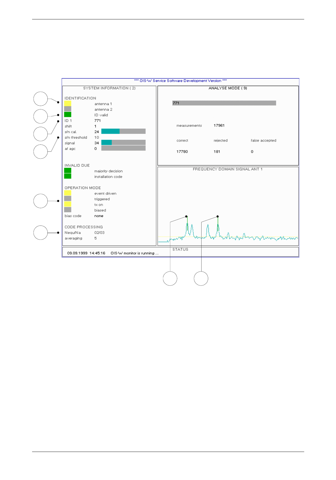
5.1.6 Control of the Settings
Check the following points:
1.
6.
2.
8.
3. 4.
7.
5.
Picture 5-3: control picture identification
1. The identification is made with the selected antenna (A).
If not: Correct the parameter „Ant“.
2. The operation mode corresponds to the one that you really want.
If not: Correct the parameters „Mmain“ und „MTxuntrig“.
3. The left mark is at the calibrator.
If not: Correct the parameters „InitDelay“ und „DelayRange“.
4. The right mark is at the last signal peak.
If not: Use the tags (T) which have been configured for your system.
5. S/N is higher than S/N Threshold.
If not: Check the presence and the orientation of the tag (T).
Optimize the whole arrangement; reading range, angles
Reduce the parameter „SNR“; it is a matter of fact that this may reduce the reading
security.
Baumer Ident AG 60 / 61
Author: Clemens Zehnder File: Maintenance-SW.doc Version 3.0 e
6. The ID Valid Flag shines green if the identification is successful.
If not: Repeat steps 1 - 6.
7. The number in the output mask (OM) corresponds to the current tag (T).
If not: The tag structure settings (configuration file) doesn’t correspond to your tags (T). You
have the possibility to change the tag structure with the Service Software Development.
8. The reading security is sufficient.
If not: Raise the parameters „Nequ“ und „Na“.
As a matter of fact this will extend the internal decoding time and reduce the maximum
possible speed of the objects which ought to be identified.
9. The reader status of ant 1 (R09) on the front panel shines green.
10. The detection status of ant 1 (R10) on the front panel shines green.
11. Press „d“ and you will see the outgoing data telegram at the service interface.
Picture 5-1: control picture data
12. Press „d“
13. Press „ESC“ to close the application „Service Software Development“.
Baumer Ident AG 61 / 62
Author: Clemens Zehnder File: Maintenance-SW.doc Version 3.0 e
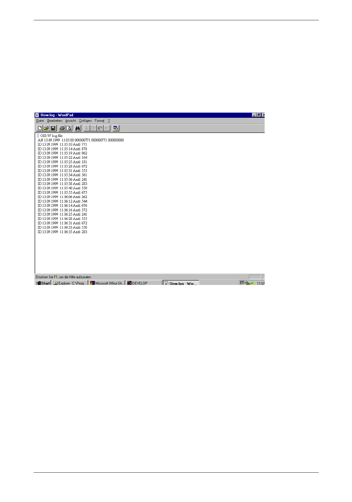
5.1.7 Log-File
Open the file oisw.log in the working directory with the help of a text editor (e.g. wordpad). Check the past
readings.
Please note:
Whenever you start up the application, the file oisw.log will be recreated and the old entries will be
deleted.
picture 5-2: file "oisw.log"

Baumer Ident AG 62 / 63
Author: Clemens Zehnder File: Maintenance-SW.doc Version 3.0 e
5.2 Access Control
Not yet released!

Baumer Ident AG 63 / 64
Author: Clemens Zehnder File: Maintenance-SW.doc Version 3.0 e
6 If you have a Problem
The following enumeration list is constantly updated.
• The Service Software Basic (S01 doesn’t start up correctly and indicates the following error
message:
error: can’t set serial port settings
⇒ Please check the correct spelling (capital letters) in the instruction line:
Develop.exe COM1 BAUD115200
• The Service Software Basic (S01 starts up correctly but the communication to the reader (R)
doesn’t establish itself.
⇒ Activate the interface on your PC.
(Control panel \ System \ device manager \ LPT and COM devices)
• The red LED system failure 1 (R12) shines constantly after start up
⇒ You have the possibility to reset the reader (R) with the keystroke on „r“ on your PC. Or you can just
switch off and on the reader (R) with the mains switch (R35. If the system failure 1 (R12) is still on, the
reader (R) has a problem which cannot be fixed by the user. Please contact us.
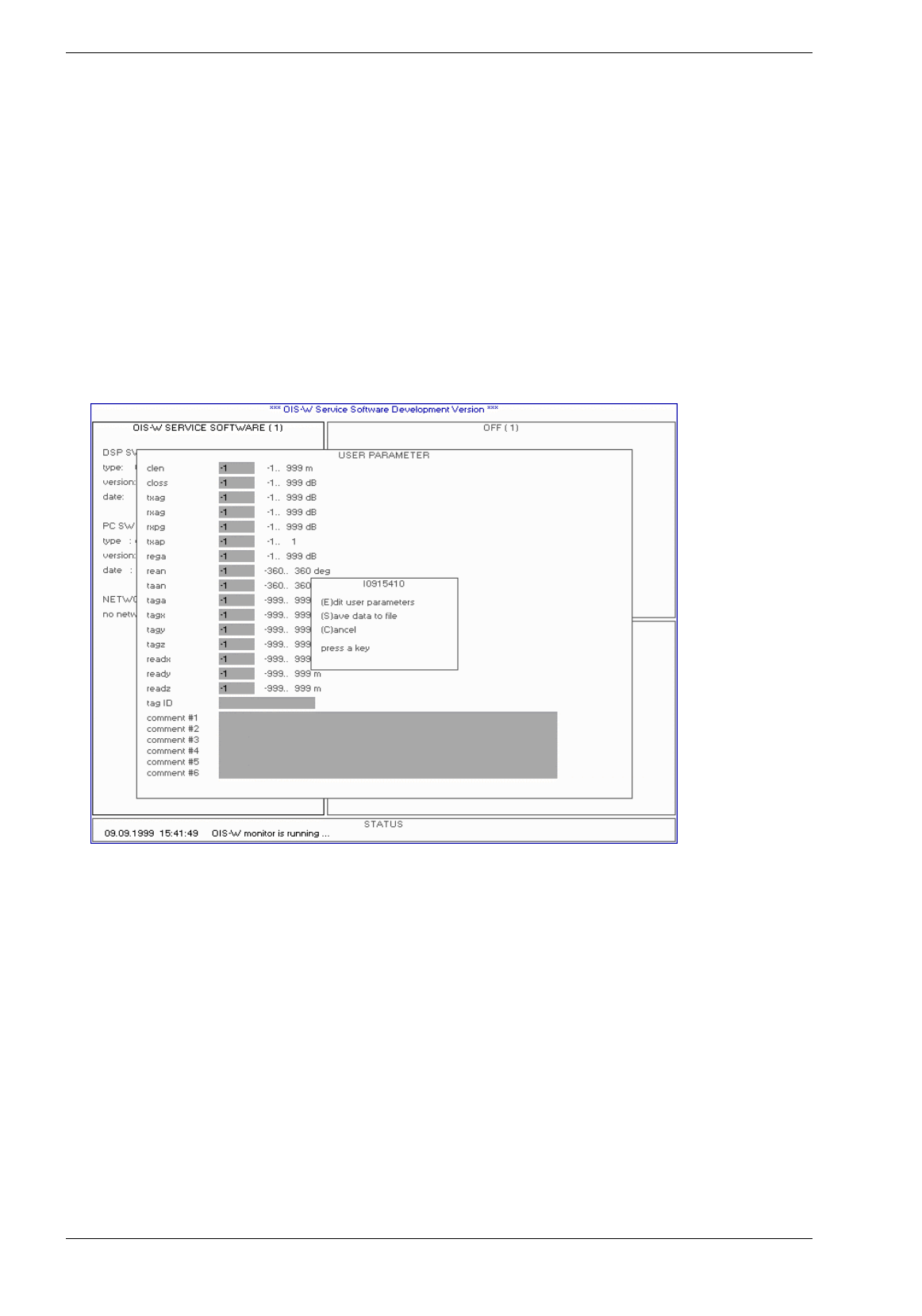
Baumer Ident AG 64 / 65
Author: Clemens Zehnder File: Maintenance-SW.doc Version 3.0 e
7 Remote Diagnostics
Please follow the steps below in order to save reader data into a data file. This data file will contain all the
relevant information about the tag, the reader and the environment, which Baumer Ident needs to check
the identification.
1. Start up the application Service Software Development and press „s“.
The following picture will appear:
Picture 7-1: remote diagnostics
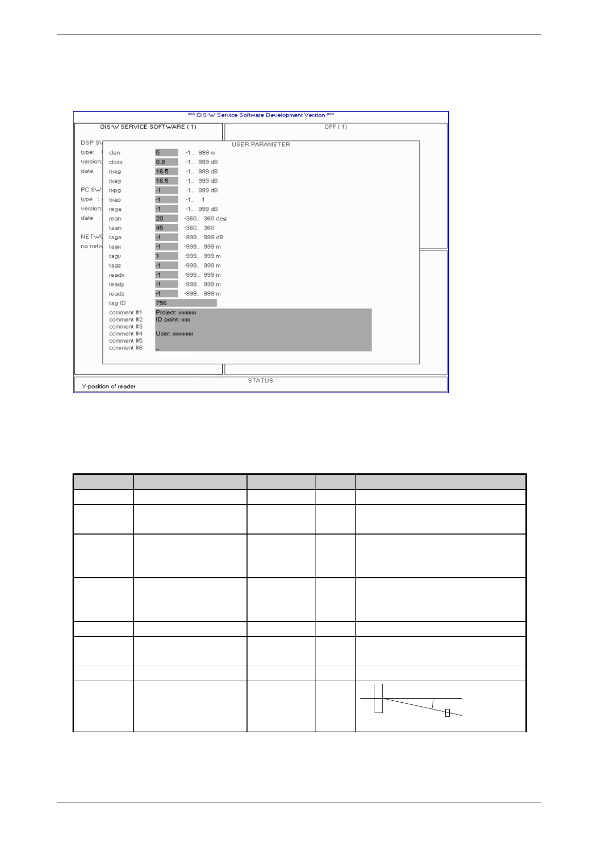
Baumer Ident AG 65 / 66
Author: Clemens Zehnder File: Maintenance-SW.doc Version 3.0 e
2. Press „E“ for editing the values for the parameters of the current application.
Picture 7-2: remote diagnostics
3. Insert the required values and press „enter“.
Term Description Range Default Remarks
clen cable length -1 ... 999 m 5
closs cable loss per meter -1 ... 999 dB 0.8 0.4 dB/m: WC-1xxx
0.8 dB/m: WC-0xxx
txag TX antenna gain -1 ... 999 dB 14.5 8.5 dB: WA-x1xx
14.5 dB: WA-x3xx
16.5 dB: WA-x4xx
rxag RX antenna gain -1 ... 999 dB -14.5 8.5 dB: WA-x1xx
14.5 dB: WA-x3xx
16.5 dB: WA-x4xx
rxpg RX preamp. Gain -1 ... 999 dB 0 only when using an additional rx preamplifier
txap TX amp. Present -1 ... 1 0 0: without additional tx amplifier
1: with additional tx amplifier
rega reader gain -1 ... 999 dB 0 in preparation
rean reader angle -360 ... 360 deg 0 rean
Ant Tag
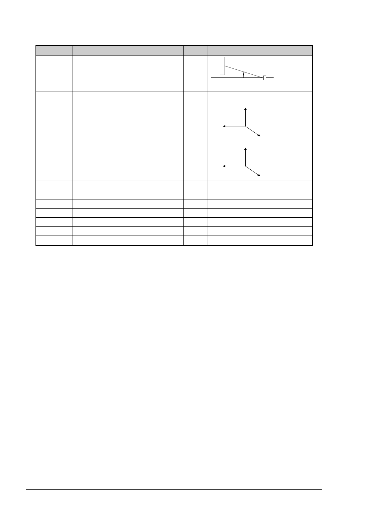
Baumer Ident AG 66 / 67
Author: Clemens Zehnder File: Maintenance-SW.doc Version 3.0 e
Term Description Range Default Remarks
taan tag angle -360 ... 360 deg 0
Ant Tag
taan
taga tag gain -999 ... 999 dB 0 in preparation
tagx
tagy
tagz
X-position of tag
Y-position of tag
Z-position of tag
-999 ... 999 m
-999 ... 999 m
-999 ... 999 m
0
1
0
x
z
y
readx
ready
readz
X-position of reader antenna
Y-postion of reader antenna
Z-position of reader antenna
-999 ... 999 m
-999 ... 999 m
-999 ... 999 m
0
0
0
x
z
y
tag ID tag identification code
comment # 1 project
comment # 2 id-point
comment # 3 user
comment # 4
comment # 5
comment # 6
Table 7-1: parameters of the data file
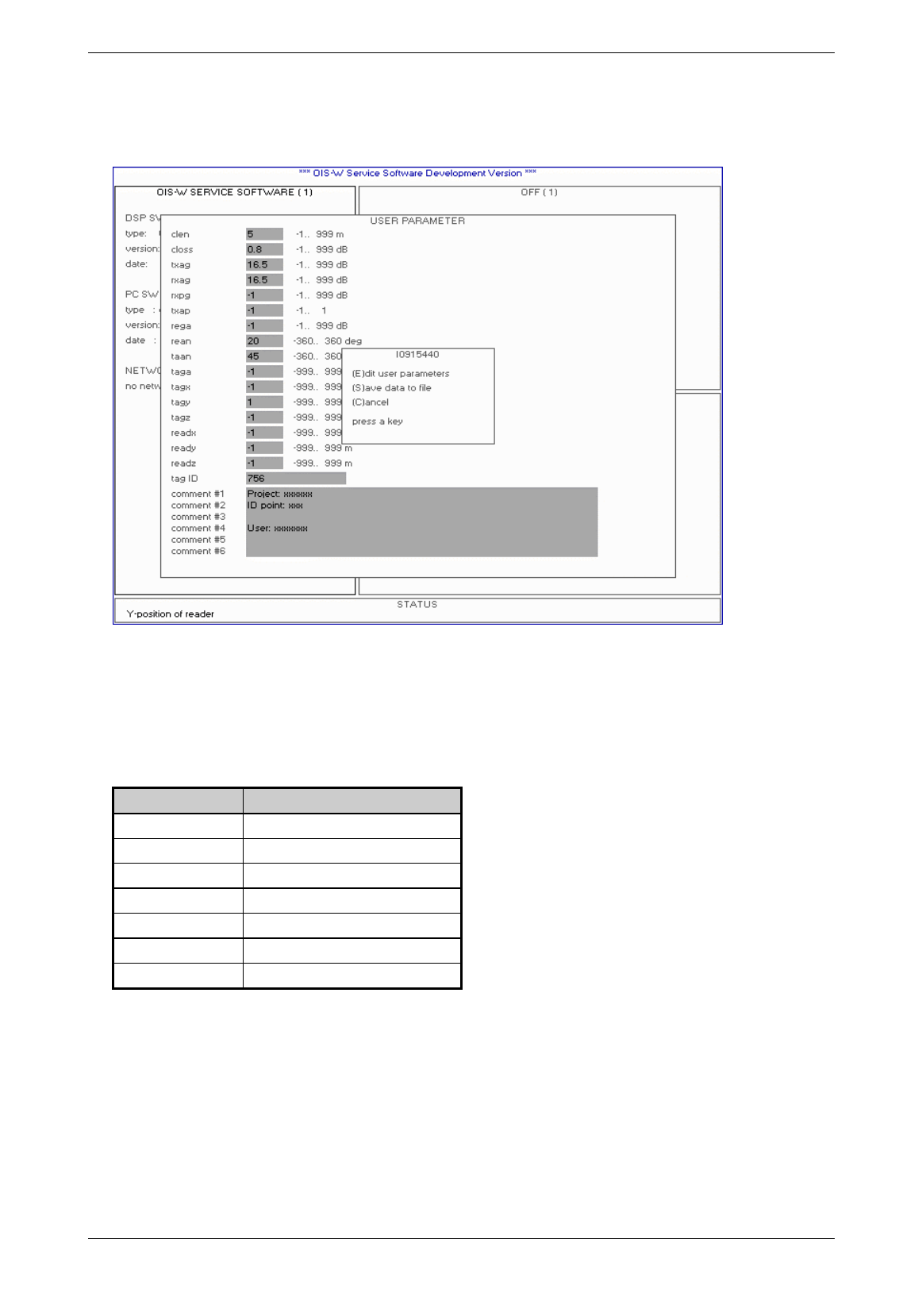
Baumer Ident AG 67 / 68
Author: Clemens Zehnder File: Maintenance-SW.doc Version 3.0 e
4. Press „enter“ after the last input line (comment # 6).
Picture 7-3: remote diagnostics
5. Press „s“ when the tag gets into the reading area of the antenna and reaches the planned reading
position.
The following data file(s) will be created in the working directory:
Terms Description
filename: "Mddhhmmi.ccc"
m = month (A=january, B=february ...)
dd = day (01..31)
hh = hour (00..23)
mm = minute (00..59)
i = index (0..9)
cou = counter from 000 to 999
Table 7-2: name of data file
The numbers of data file which will be created by pressing „s“ are variable (see parameter Nfiles on
page26).
6. Send the created data file(s) to Baumer Ident AG by e-mail.
7. Baumer Ident will check the data and make an action plan in collaboration with the user to optimize the
identification.
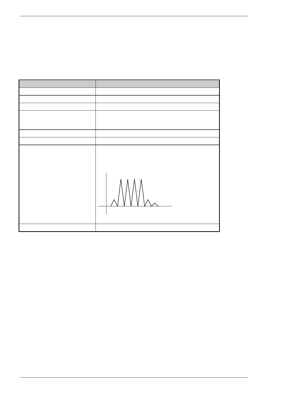
Baumer Ident AG 68 / 69
Author: Clemens Zehnder File: Maintenance-SW.doc Version 3.0 e
8 Glossary
The table is constantly updated.
Term Remarks
DSP Digital Signal Processor
FPGA Field Programmable Gate Array
DDS Direct Digital Synthesizer
IP Protective quality for protection against direct contact, protection
against ingress of solid foreign bodies and protection against spraying
water.
SMA Standard connection
TNC Standard connection
Calibrator / Signal-Peak The response signal of the tag (T) consists of several peaks
(frequency domain). The first from the left is called Calibrator (C) and
the following are called signal peaks (S). The response signal of a
code with 3 digits consists of one calibrator and three signal peaks.
CSSS
Bin 1 Bin = 12.5 ns
Table 8-1: glossary

Baumer Ident AG 69 / 70
Author: Clemens Zehnder File: Maintenance-SW.doc Version 3.0 e
9 Notice