Baumer Electric OIS-W-WR300303 RF-Identification System User Manual Maintenance
Baumer Electric AG RF-Identification System Maintenance
UserManual.wiki
>
Baumer Electric
>
OIS-W-WR300303 User Manual
>
Maintenance
Contents
1.
Installation
2.
Interface
3.
Maintenance
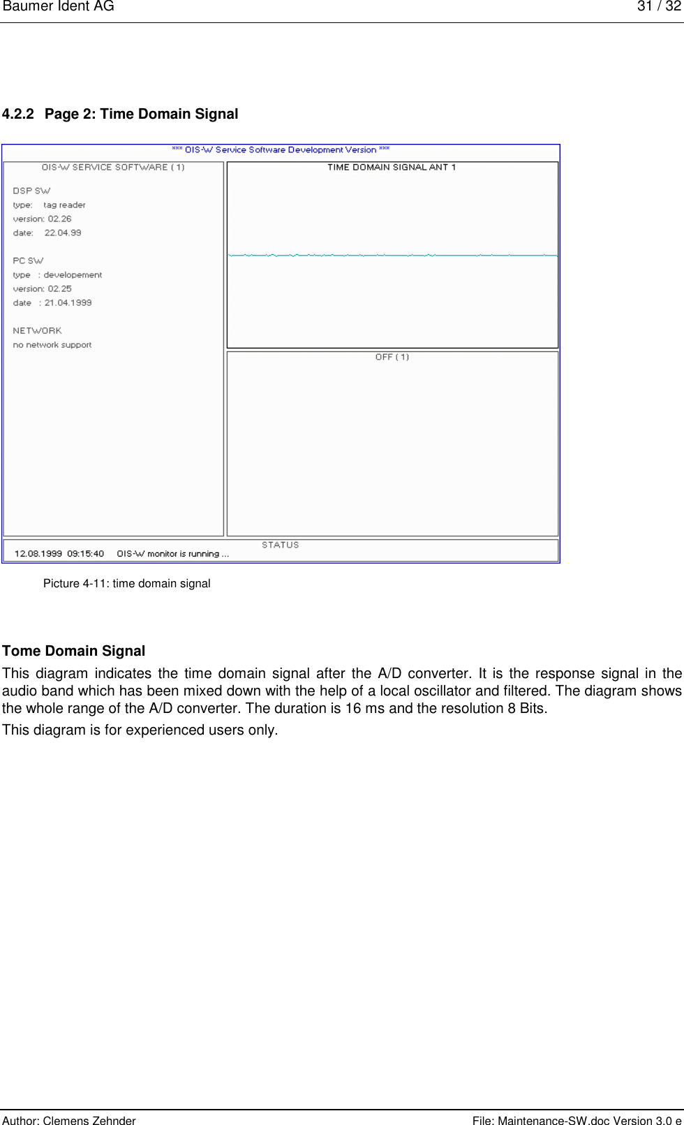
Maintenance
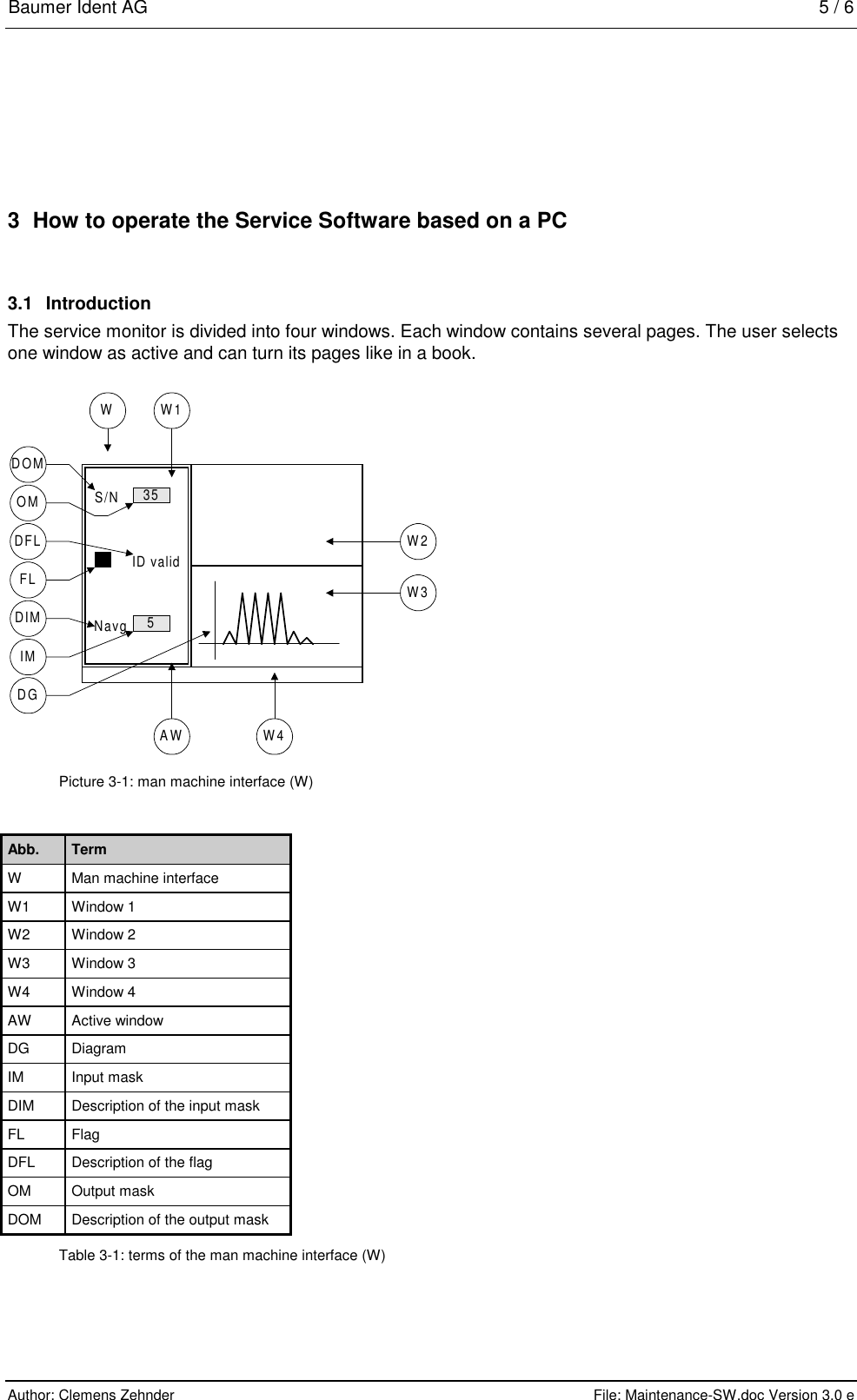
Navigation menu
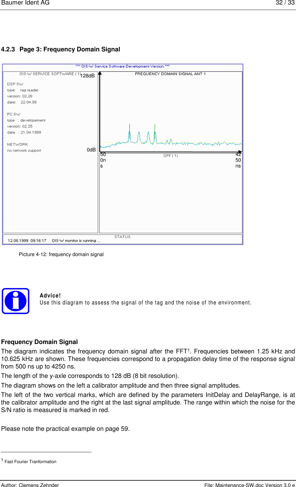
Upload a User Manual
Namespaces
Wiki Guide
HTML
PDF
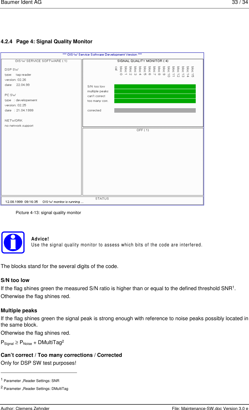
Info
Views
User Manual
Discussion / Help
Navigation
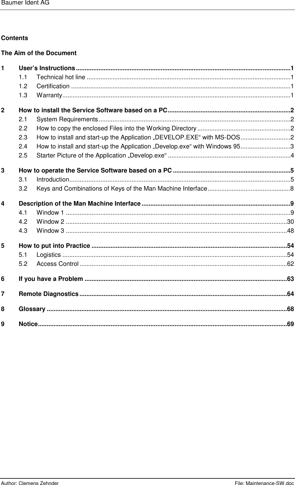
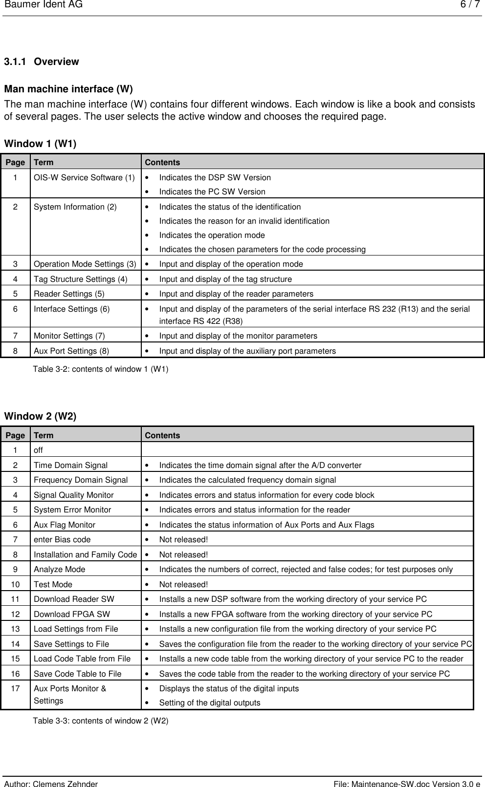
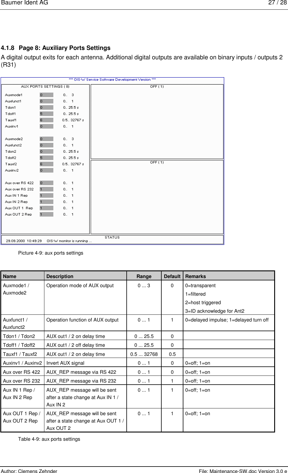
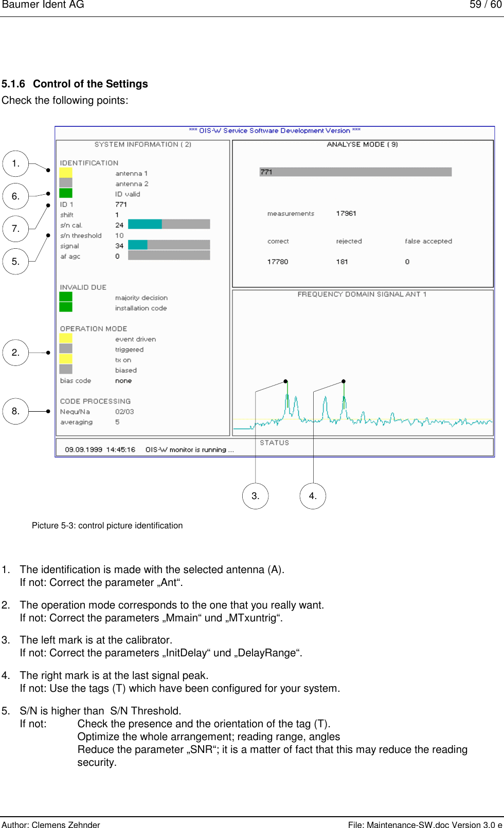
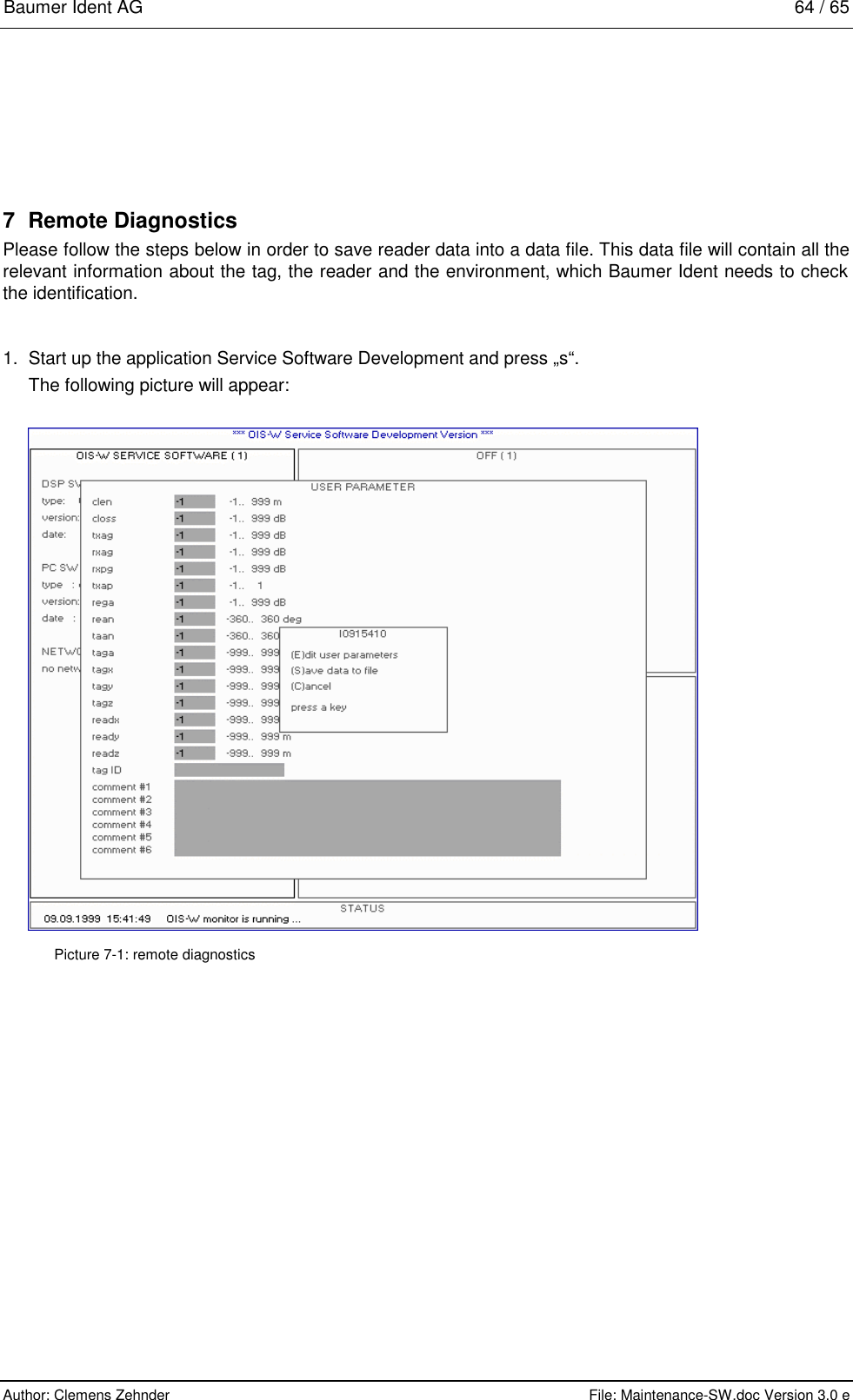
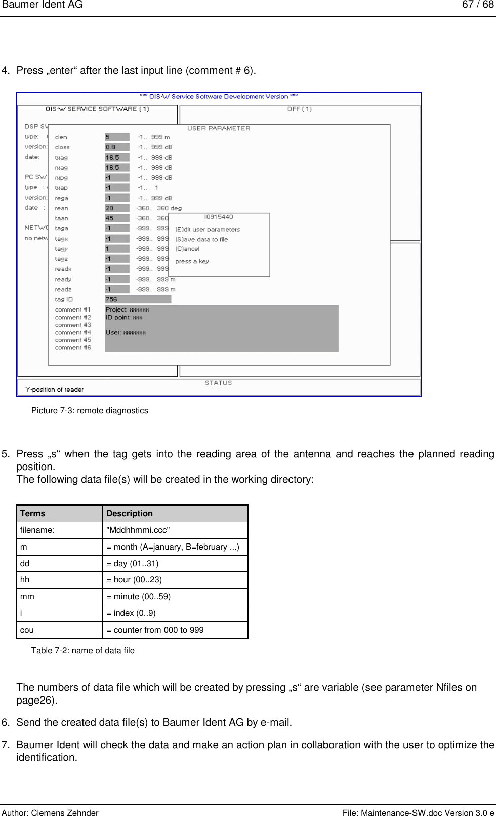
![Baumer Ident AG 10 / 11 Author: Clemens Zehnder File: Maintenance-SW.doc Version 3.0 e 4.1.2 Page 2: System Information All parameters which are mentioned in the following text are explained in detail in chapters 4.1.3 - 4.1.5. Picture 4-2: system information Antenna 1 / Antenna 2 If the flags shine yellow the respective antenna is used. The display corresponds to the parameter „Reader Settings: Ant“. ID valid The flag shines green if a valid tag (T) is recognized. It gives the same information as the LED detection status of ant 1 (R10) on the front panel. ID This output mask (OM) shows the decoded code. Shift This output mask (OM) indicates where the calibrator has been detected in the unit [Bin] within the delay range. S/N cal. This output mask (OM) indicates the measured signal-to-noise ratio in the unit [dB]. The signal is measured at the recognized calibrator and the noise within the range defined with the parameter „Reader Settings: Tnoise0“.](https://usermanual.wiki/Baumer-Electric/OIS-W-WR300303.Maintenance/User-Guide-141772-Page-15.png)
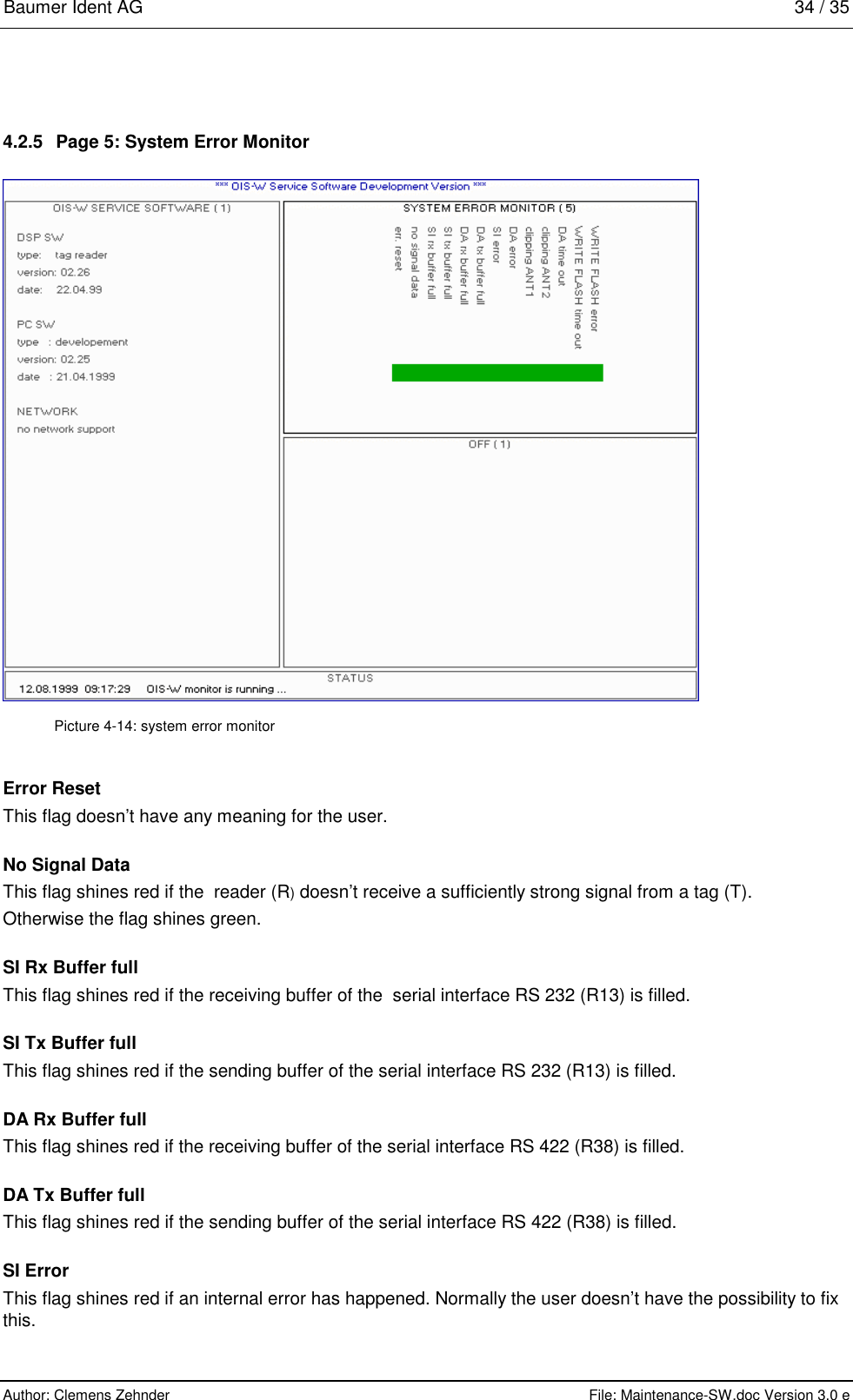
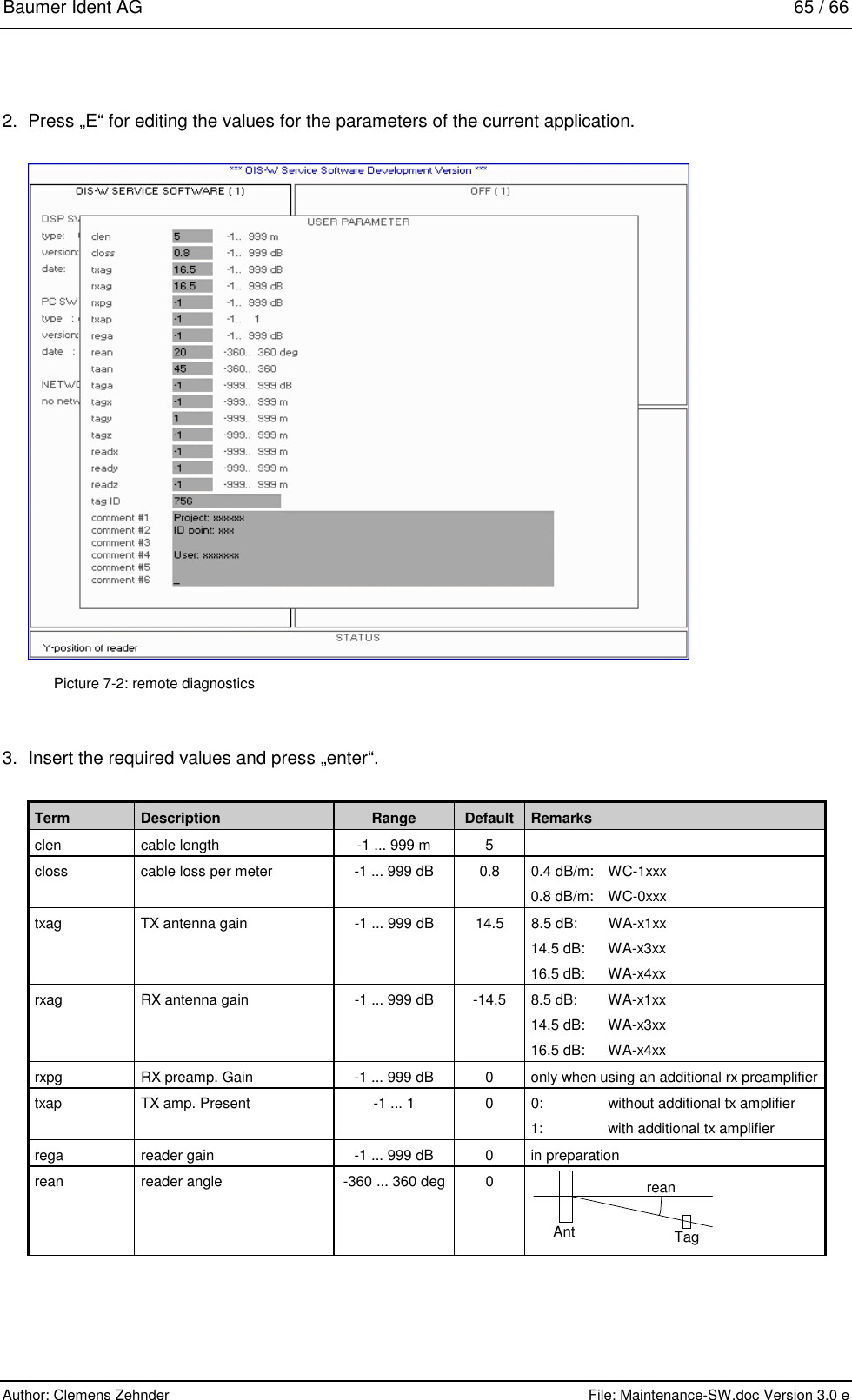
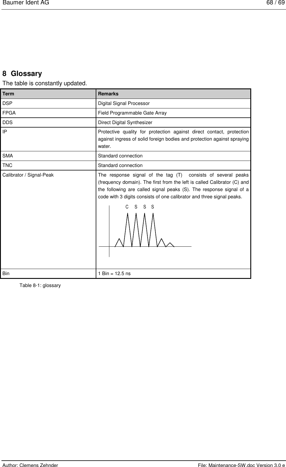
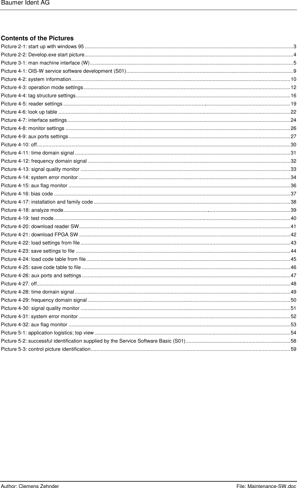
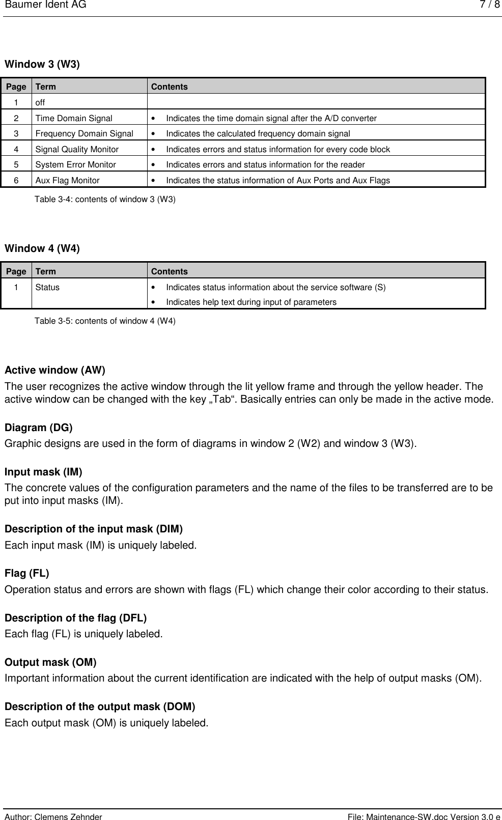
![Baumer Ident AG 11 / 12 Author: Clemens Zehnder File: Maintenance-SW.doc Version 3.0 e S/N Threshold This output mask (OM) indicates the S/N threshold in the unit [dB]. It corresponds to the parameter „Reader Settings: SNR“. Signal This output mask (OM) indicates the signal level of the calibrator in the unit [dB]. AF AGC This output mask (OM) indicates the value of the automatic gain control. The user doesn’t have the possibility the change this parameter. Invalid Due If this flag shines red the condition „number of equal codes out of number of measurements“ is not met. This condition is defined through the parameters „Reader Settings: Nequ and Na“. If the flag shines green the condition is met. Event Driven If this flag shines yellow the operation mode „Event Driven Mode“ is selected. The flag corresponds to the parameter „Operation Mode Settings: Mmain“. Triggered If this flag shines yellow the operation mode „Triggered Mode“ is selected. The flag corresponds to the parameter „Operation Mode Settings: Mmain“. TX ON If this flag shines yellow the reader (R) always sends out an interrogating signal. If the flag doesn’t shine the reader (R) sends out an interrogating signal only if the respective antenna (A) is triggered. The flag corresponds to the parameter „Operation Mode Setting: MTxuntrig“. Bias Code Not yet released! Nequ/Na This output mask (OM) shows the values of the parameters „Reader Settings: Nequ/Na“ an. These parameters are used for the condition „number of equal codes out of number of measurements“. Averaging This output mask (OM) indicates the value of the parameter „Reader Settings: Navg“. This parameter is used for the approximate, moving average and defines the number of measurements.](https://usermanual.wiki/Baumer-Electric/OIS-W-WR300303.Maintenance/User-Guide-141772-Page-16.png)
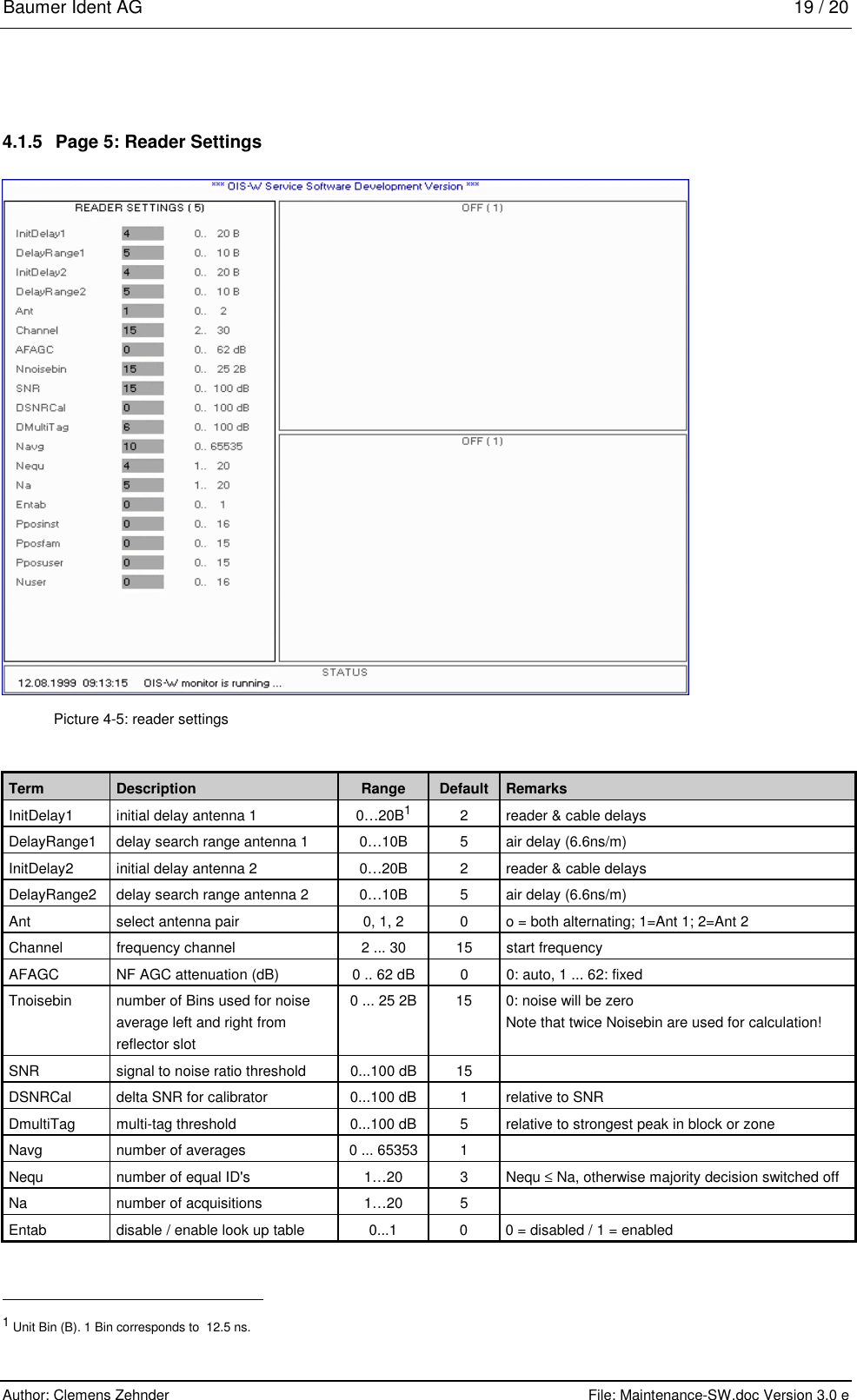
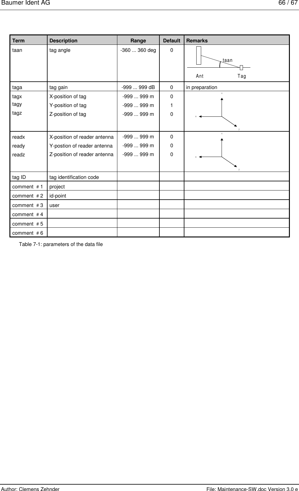
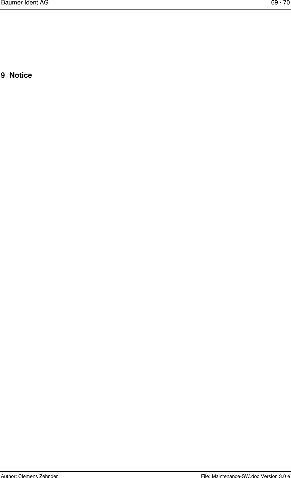
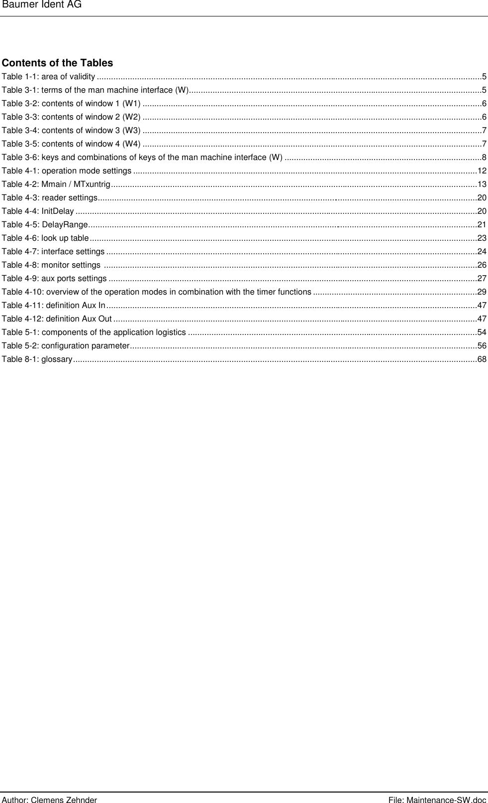
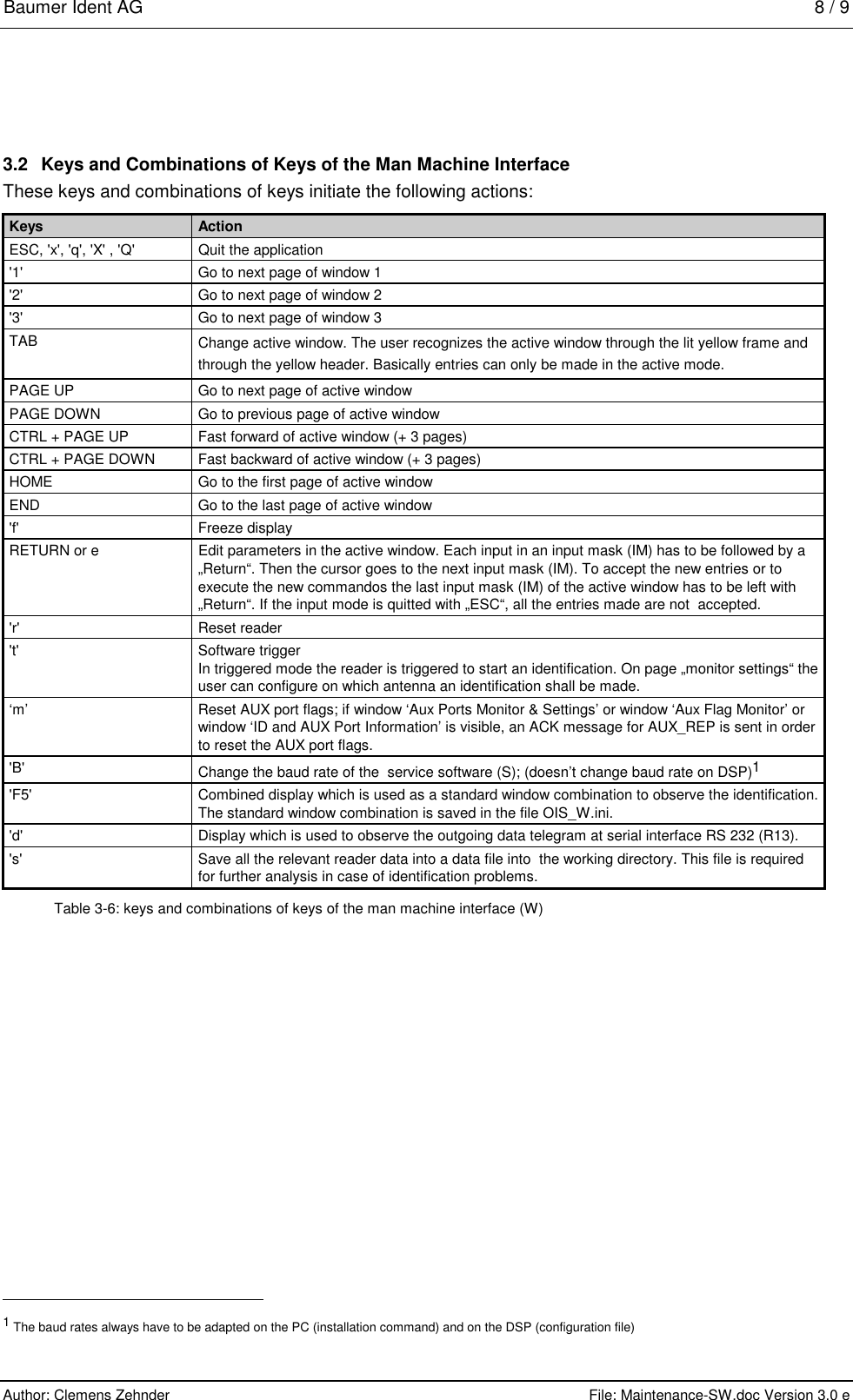
![Baumer Ident AG 20 / 21 Author: Clemens Zehnder File: Maintenance-SW.doc Version 3.0 e Term Description Range Default Remarks Pposinst first installation code block 0 ... 16 0 currently not used Pposfam first family code block 0 ... 15 0 currently not used Pposuser first user code block 0…15 0 currently not used Nuser number of user code blocks 0...16 4 Table 4-3: reader settings InitDelay1 / InitDelay2 This parameter corresponds to the signal propagation within the reader (R) and the rf cable (C). InitDelay is set separately for each antenna (A). For the calculation only the length of one rf cable (C) is used; i.e. the distance between reader (R) and antenna (A). Low-Cost rf cable Low-Loss rf cable WC-0xxx WC-1xxx Cable length InitDelay InitDelay [m] [bin] [bin] 2.5 3 3 3 4 3 5 5 5 10 10 8 15 14 11 20 18 14 25 22 17 Table 4-4: InitDelay Example: If you use the following rf cable (C): • Ant 1: 2 x 5m low-lost rf cable (C) WC-0xxx • Ant 2: 2 x 25m low-loss rf cable (C) WC-1xxx Set the following values: ⇒ InitDelay1: 5 ⇒ InitDelay2 17 DelayRange1 / DelayRange2 This parameter defines the length of the reading range which is considered when decoding the signal. DelayRange is to be set separately for each antenna (A). Please note that you only change the parameter for the internal decoding. This means that only tags(T) are decoded which are within the limits defined by the parameters InitDelay and DelayRange. These parameters don’t influence the maximum reachable reading range of the system.](https://usermanual.wiki/Baumer-Electric/OIS-W-WR300303.Maintenance/User-Guide-141772-Page-25.png)
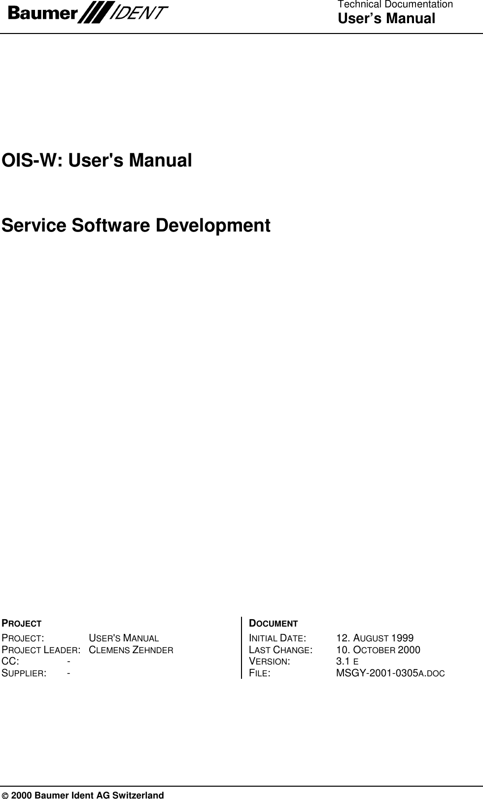
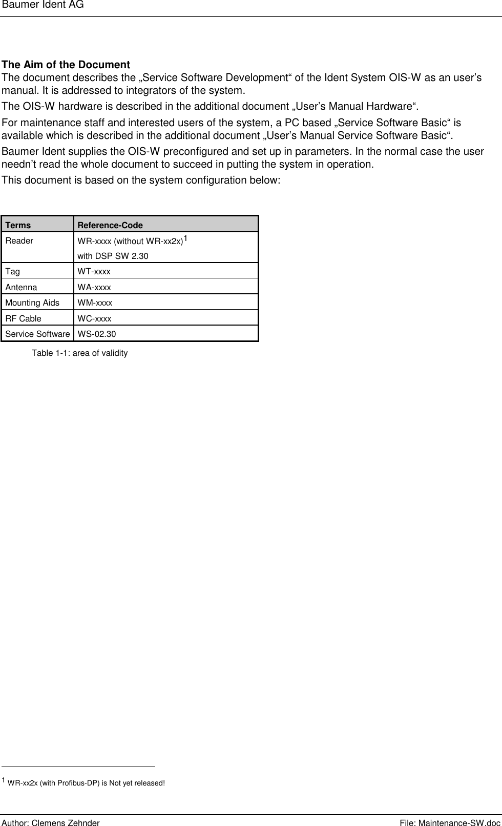
![Baumer Ident AG 21 / 22 Author: Clemens Zehnder File: Maintenance-SW.doc Version 3.0 e Range DelayRange [m] [bin] 1 1 2 2 3 2 4 3 5 3 6 4 7 4 8 5 9 5 10 6 Table 4-5: DelayRange Example: If you want to cover the following reading range: • Ant 1: 2m • Ant 2: 5m Set the following values: ⇒ DelayRange1: 2 ⇒ DelayRange2: 3 Ant There are three possibilities:: • Ant=0 both antennas are alternatively active • Ant=1 only antenna 1 is active • Ant=2 only antenna 2 is active Please note that in triggered mode the trigger event has a higher priority than the parameter „Ant“. This means that if antenna 2 is triggered at parameter settings „Ant = 1“, antenna 2 nevertheless starts a decoding. Channel This parameter defines the starting frequency of the ramp in order to adapt it to the tag medium frequency. Parameter Start-frequency 2 2402 MHz 3 2403 MHz ... ... 30 2430 MHz picture 4-3: channel AFAGC This parameter defines the NF AGC attenuation. Normally it is the best way to set this parameter at „0“, that means that NF AGC works automatically. Nnoisebin This parameter defines the number of Bins used for noise average left and right from reflector slot.](https://usermanual.wiki/Baumer-Electric/OIS-W-WR300303.Maintenance/User-Guide-141772-Page-26.png)