Baumer Electric OIS-W-WR300303 RF-Identification System User Manual Installation
Baumer Electric AG RF-Identification System Installation
UserManual.wiki
>
Baumer Electric
>
OIS-W-WR300303 User Manual
>
Installation
Contents
1.
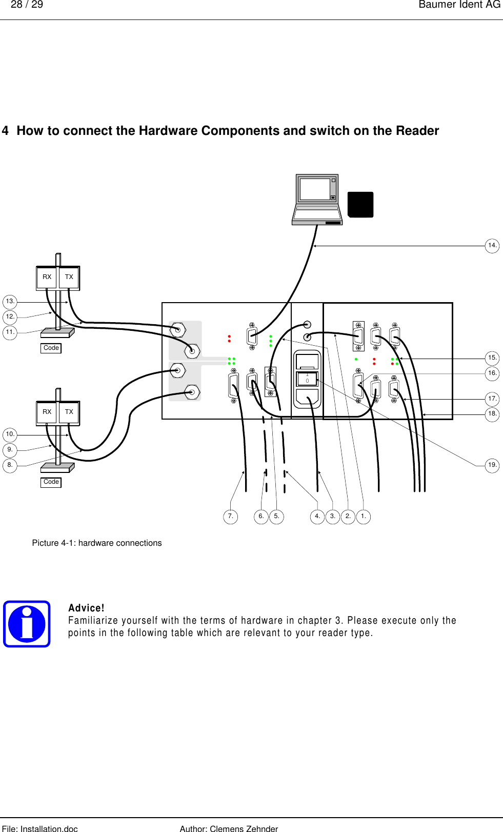
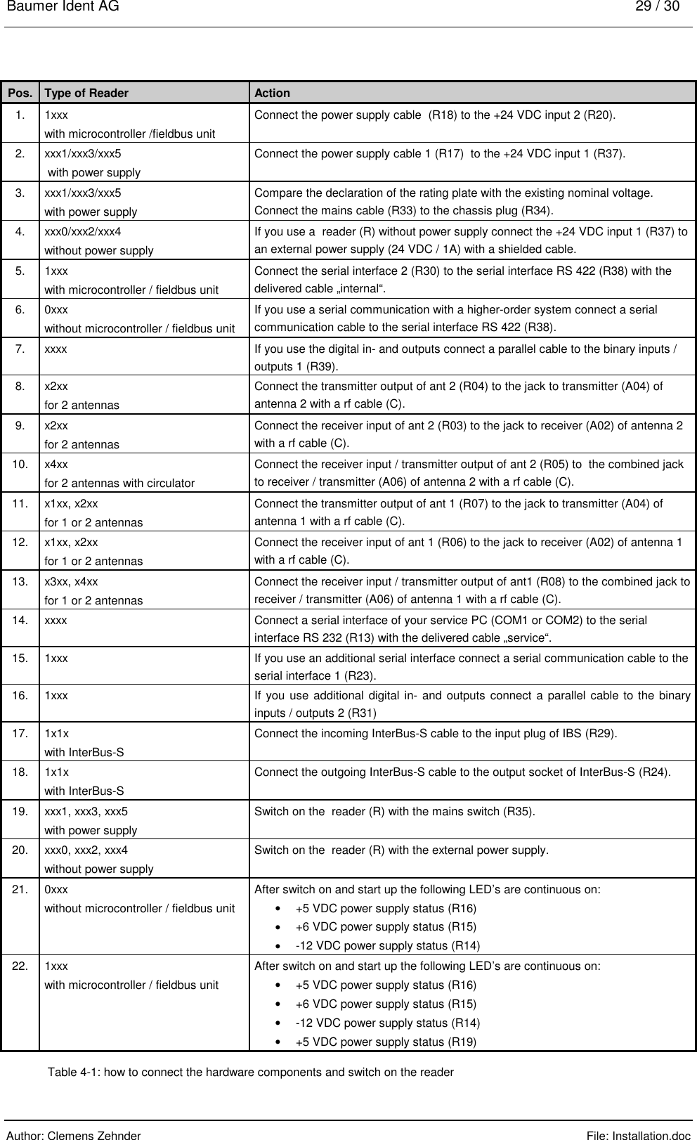
Installation
2.
Interface
3.
Maintenance
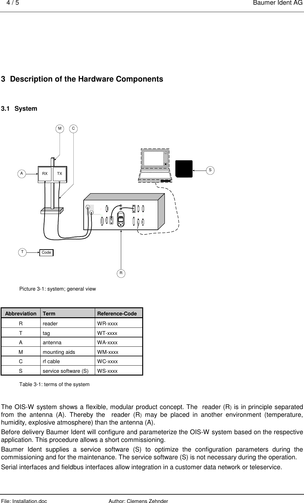
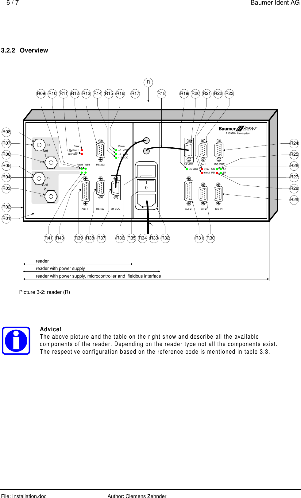
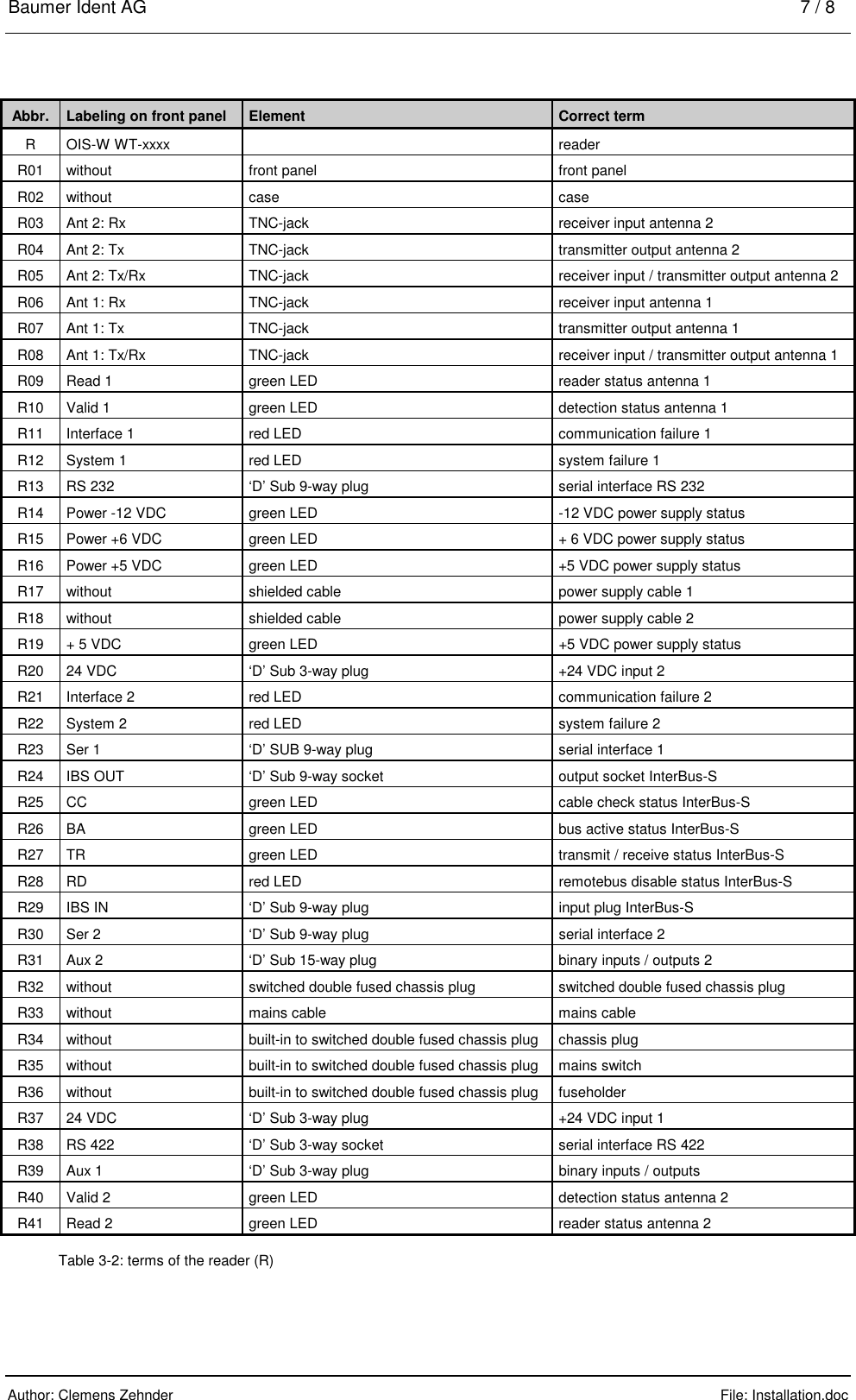
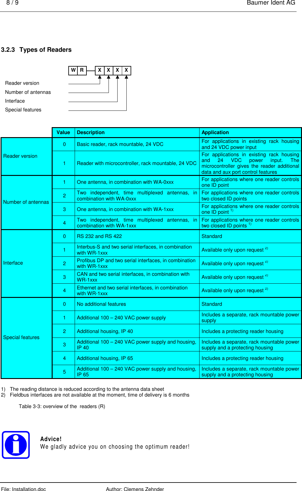
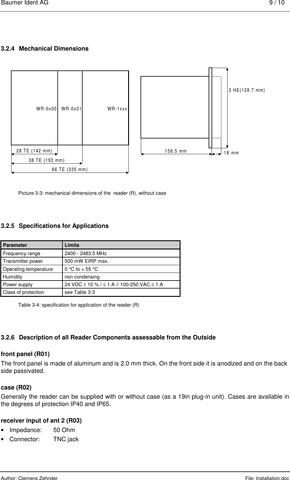
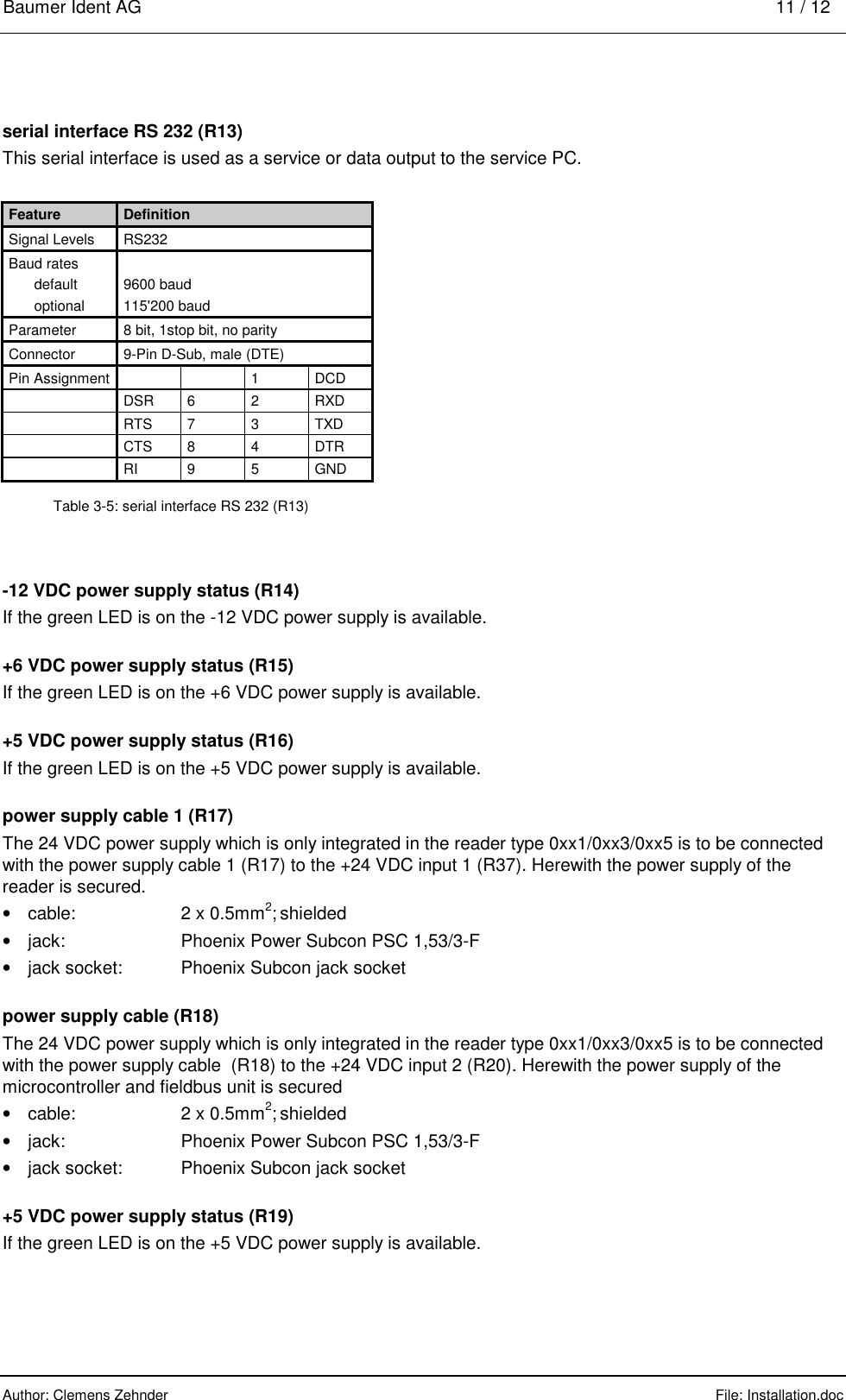
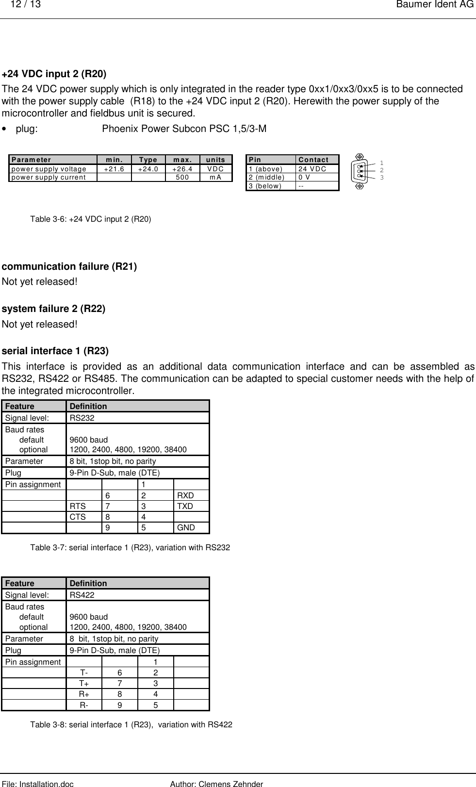
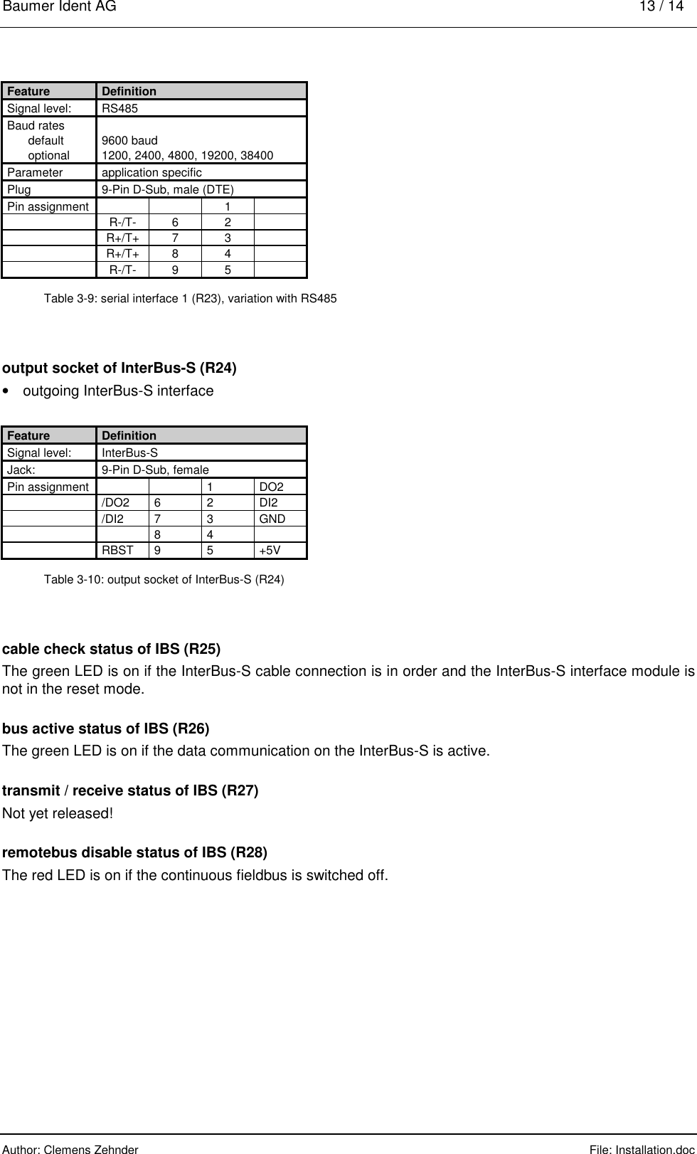
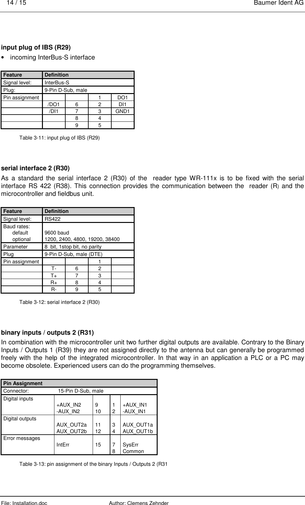
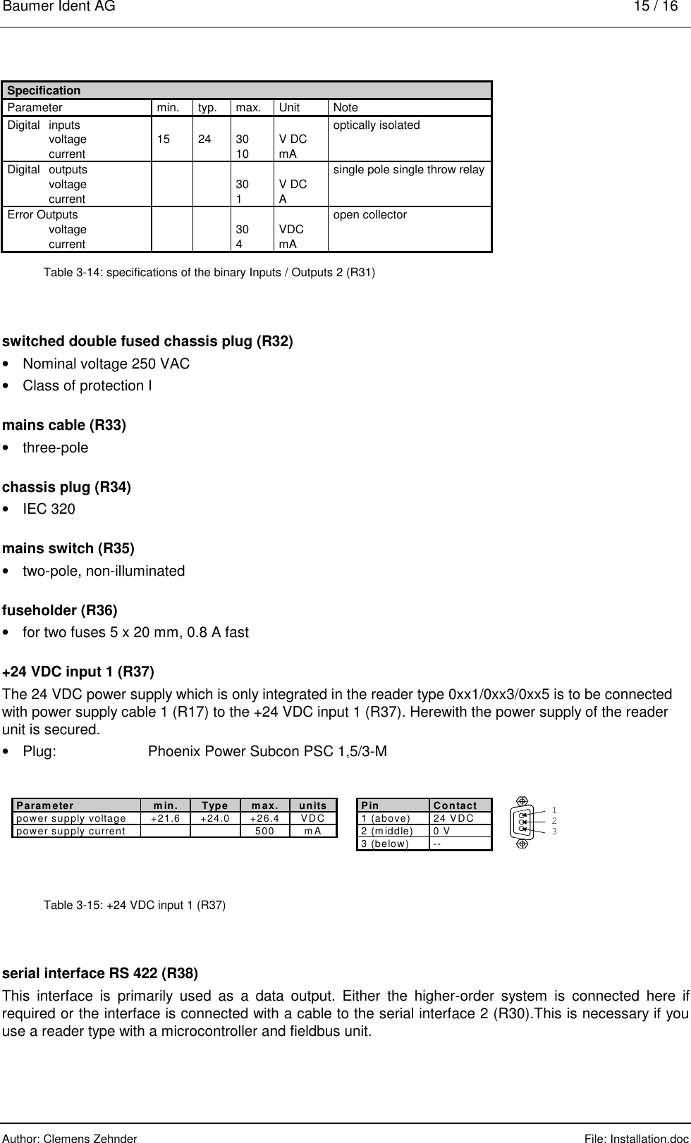
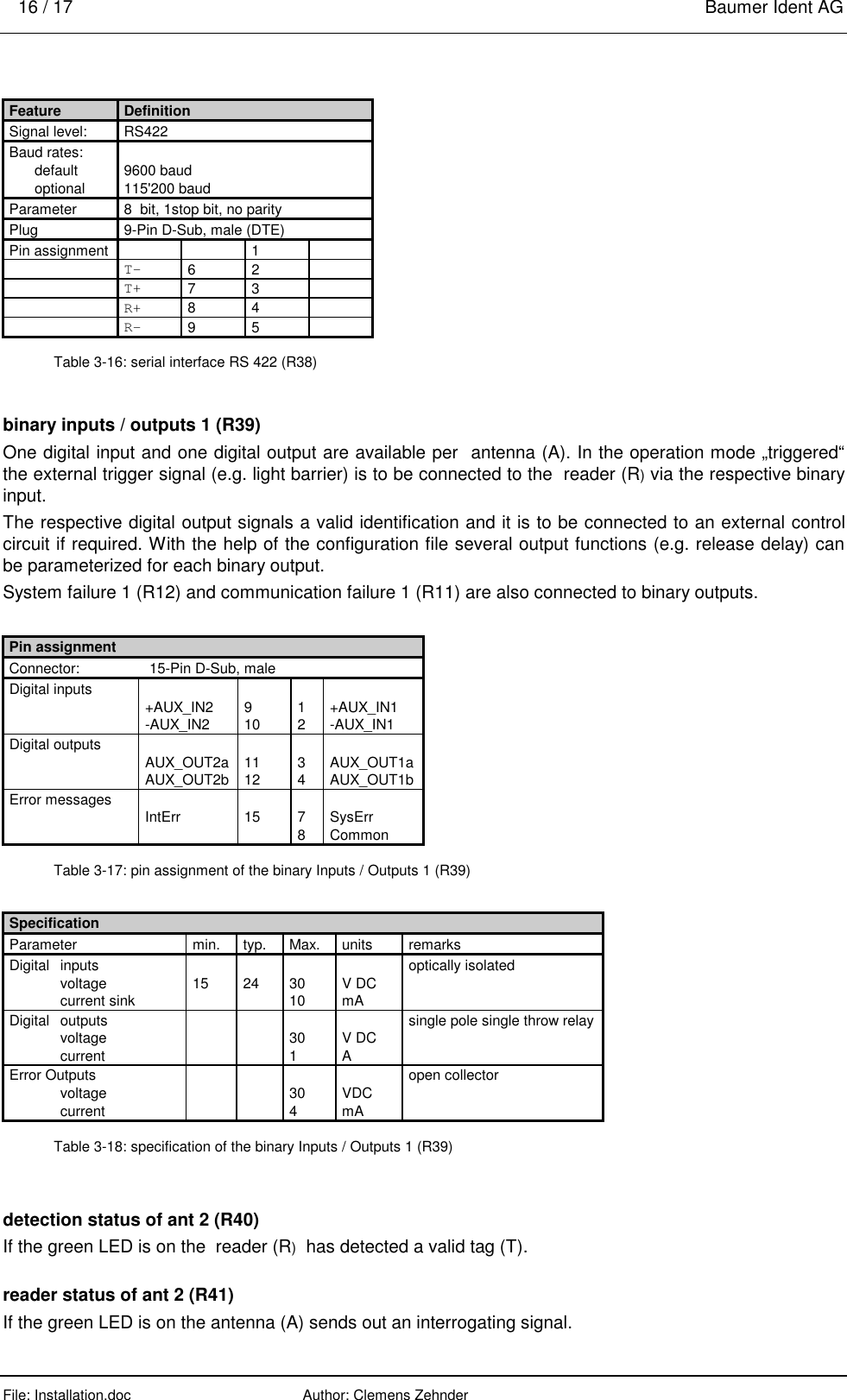
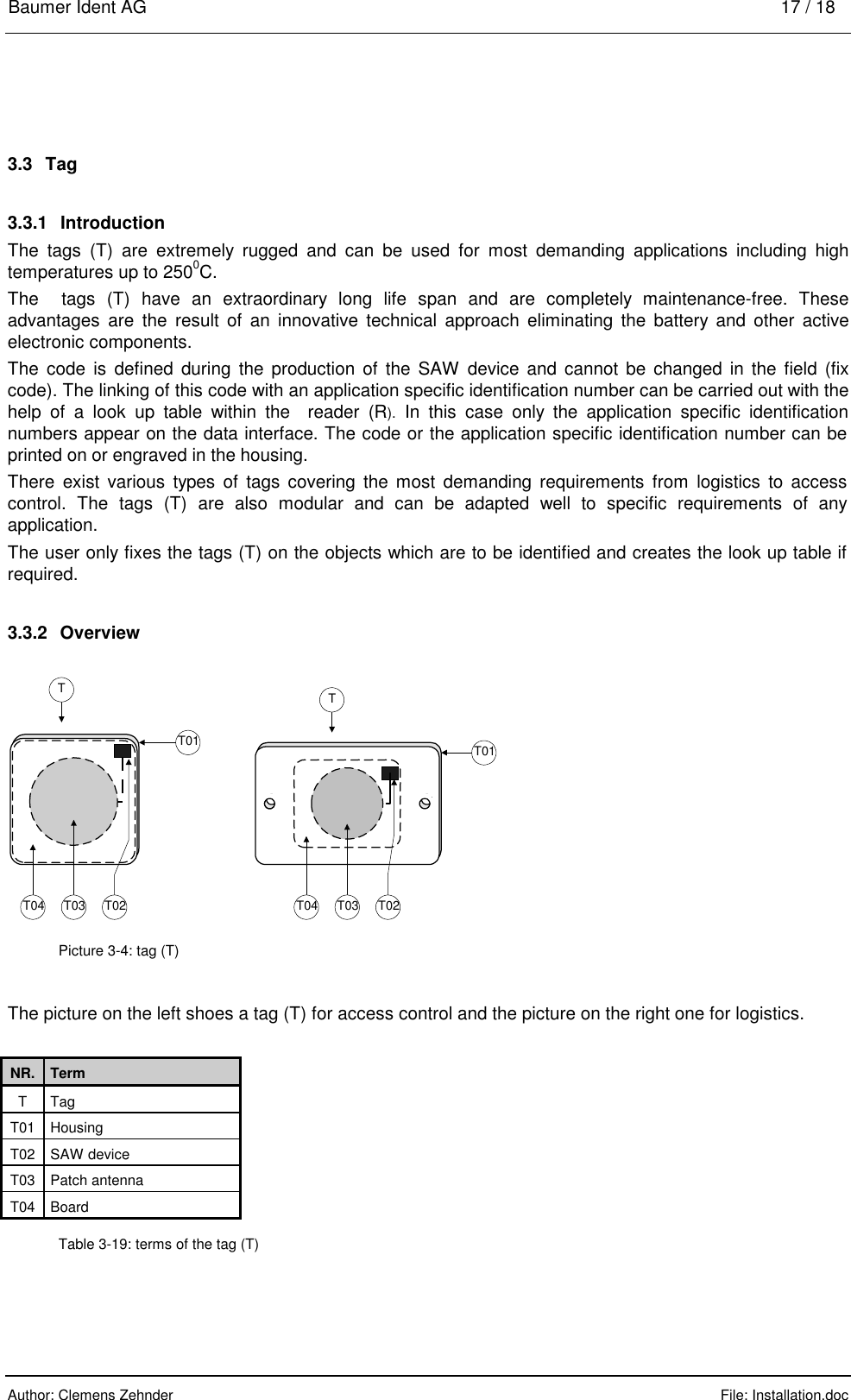
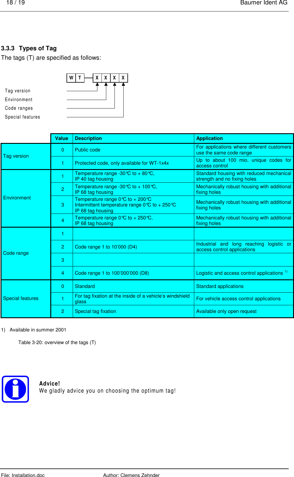
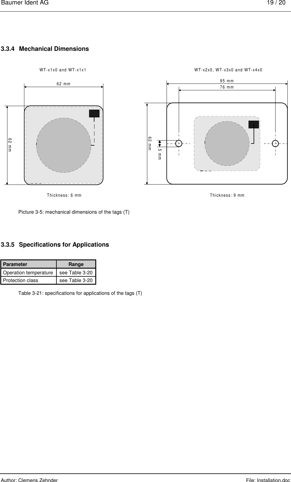
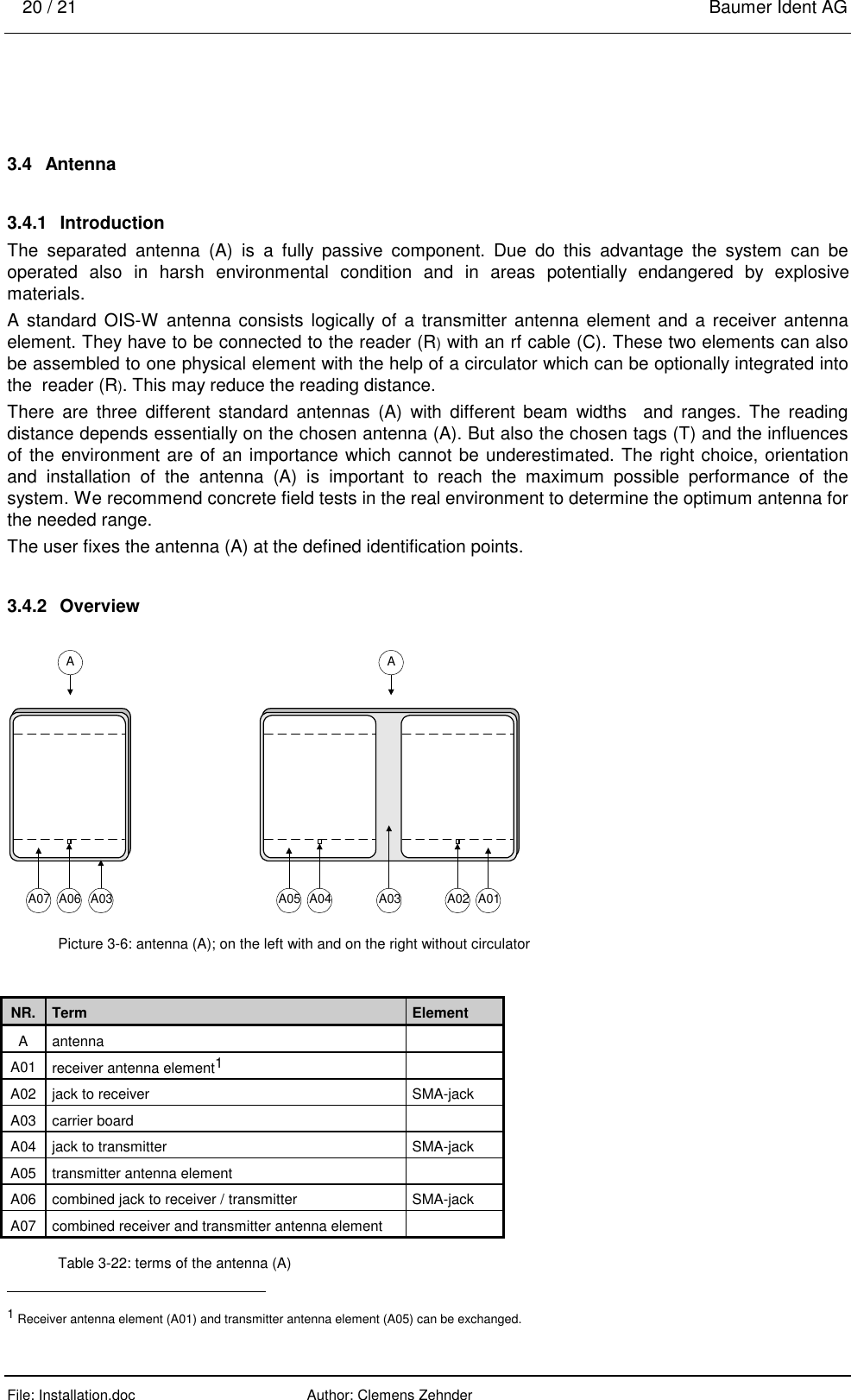
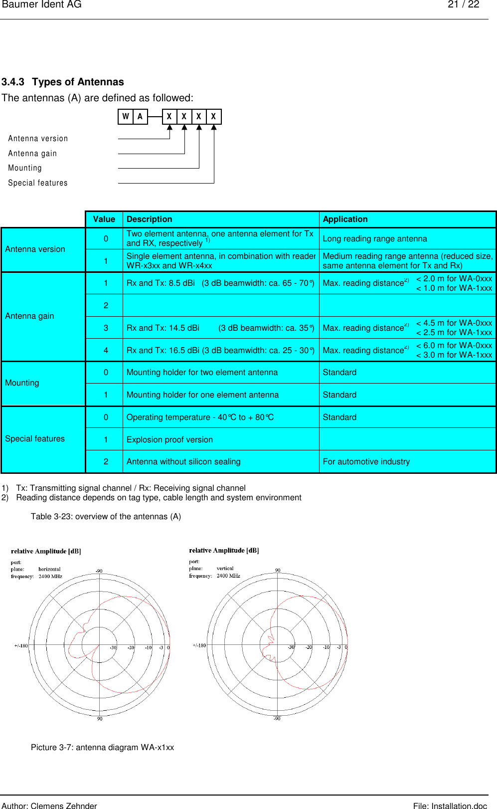
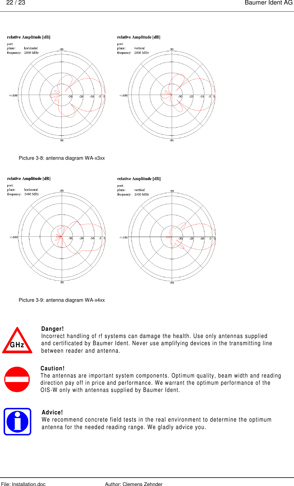
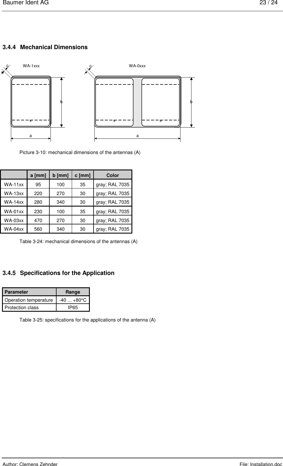
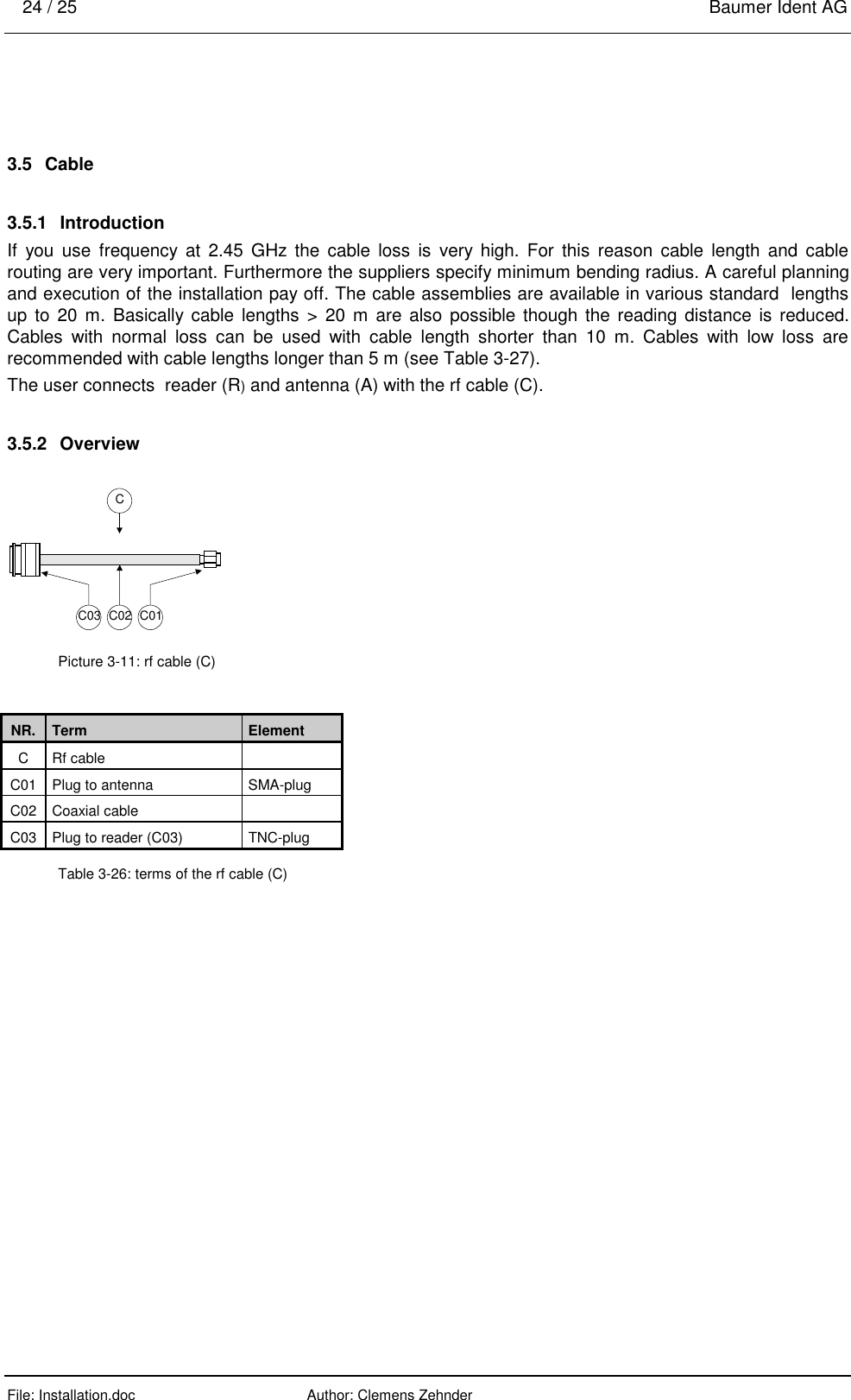
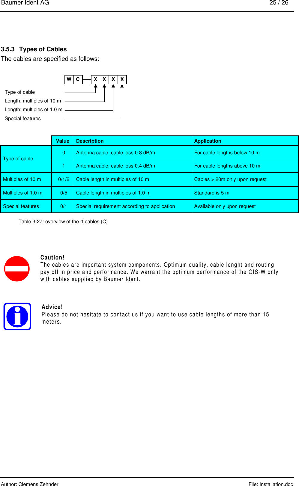
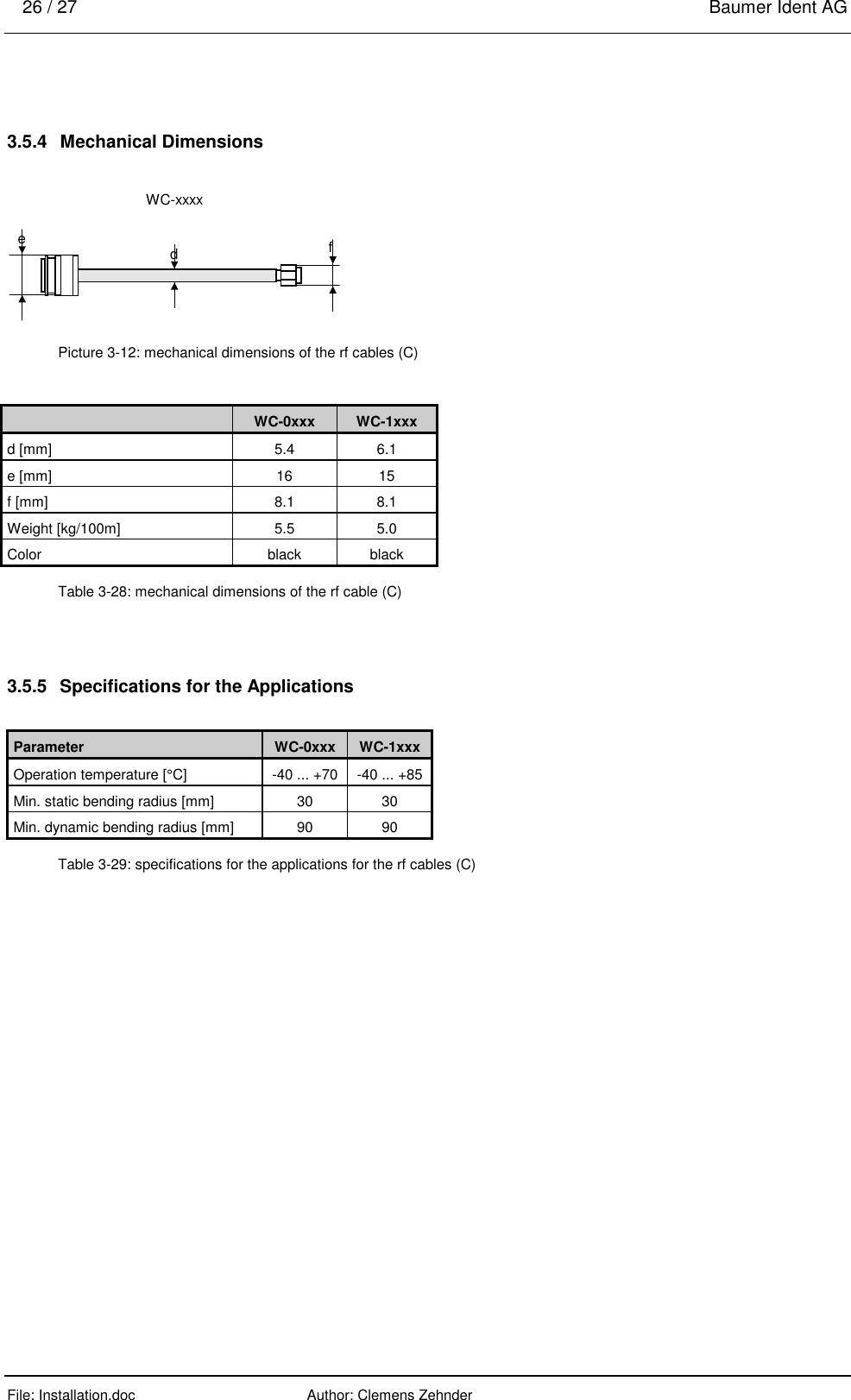
Installation
Navigation menu
Upload a User Manual
Namespaces
Wiki Guide
HTML
PDF
Info
Views
User Manual
Discussion / Help
Navigation