Baumer Electric OIS-W-WR300303 RF-Identification System User Manual Interface
Baumer Electric AG RF-Identification System Interface
UserManual.wiki
>
Baumer Electric
>
OIS-W-WR300303 User Manual
>
Interface
Contents
1.
Installation
2.
Interface
3.
Maintenance
Interface
Navigation menu
Upload a User Manual
Namespaces
Wiki Guide
HTML
PDF
Info
Views
User Manual
Discussion / Help
Navigation
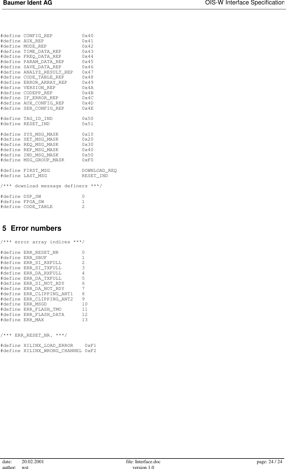
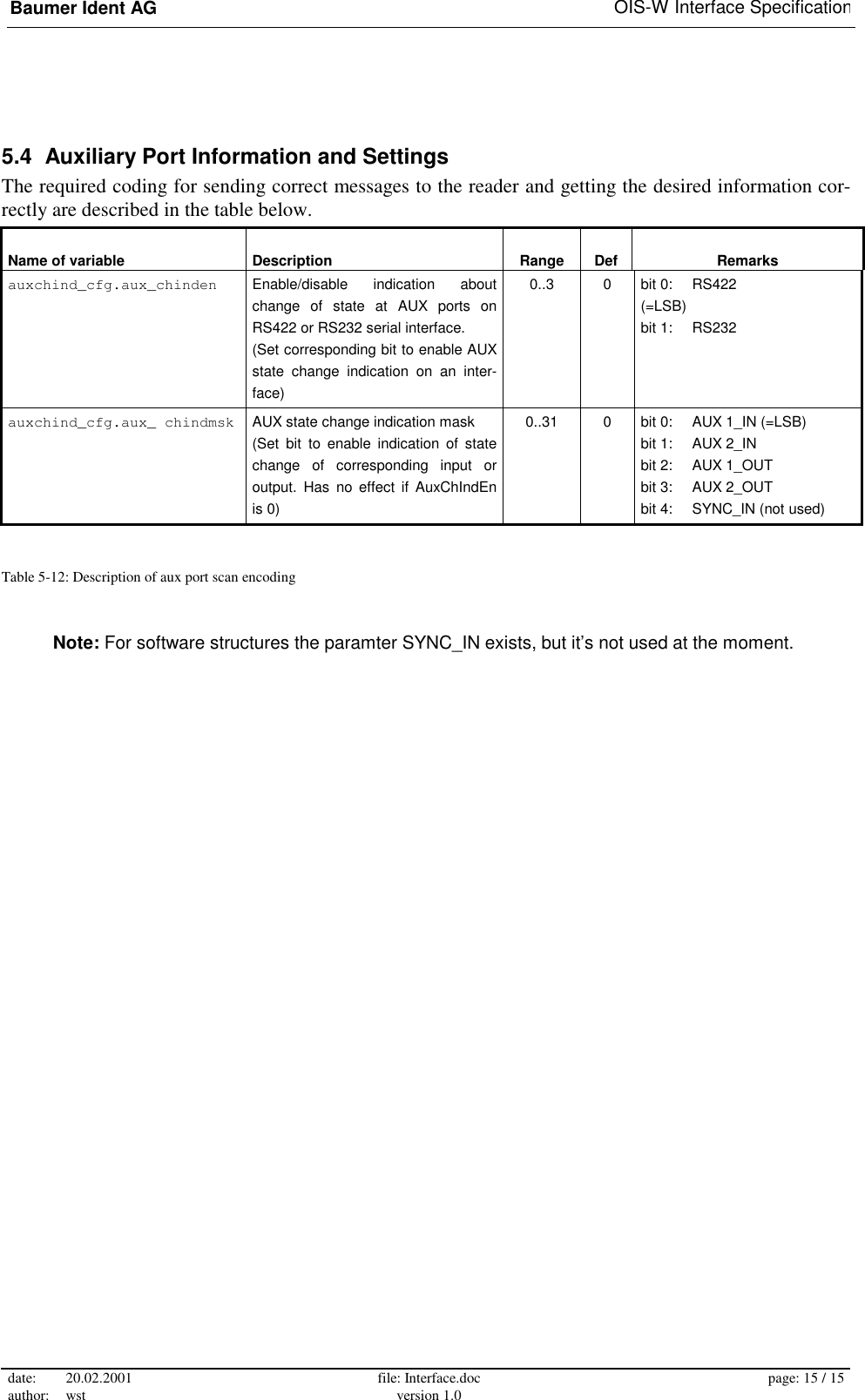
![Baumer Ident AG OIS-W Interface Specification date: 20.02.2001 author: wst file: Interface.doc version 1.0 page: 3 / 3 History 1.0 99/12/08 first draft wst 1.1 00/09/27 modification on AUX_REP message and auxiliary heg Related documents [1]: Kühn, I., STAR2 SW Interface Specification, V 1.05 (1999/11/03), Elektrobit AG [2]: Zehnder, C., OIS-W User's Manual, V 3.0E (1999/09/28), Baumer Ident AG, MSGY-2001-305 About the document This application note describes the communication protocol of the OIS-W reader unit. It is intended for system integrators who need to set up the host's part of the communication. The protocol used with the serial interfaces will be explained in detail. Disclaimer The information contained in this document is believed to be accurate and reliable. It is based on the pro-tocol stack version 2.28. However, no responsibility is assumed by Baumer Ident for its use, nor for any infringements of patents or other rights of third parties which may result from its use. No license is granted by implication or otherwise under any patent or patent rights of Baumer Ident. © Baumer Ident AG, 2000](https://usermanual.wiki/Baumer-Electric/OIS-W-WR300303.Interface/User-Guide-141771-Page-3.png)
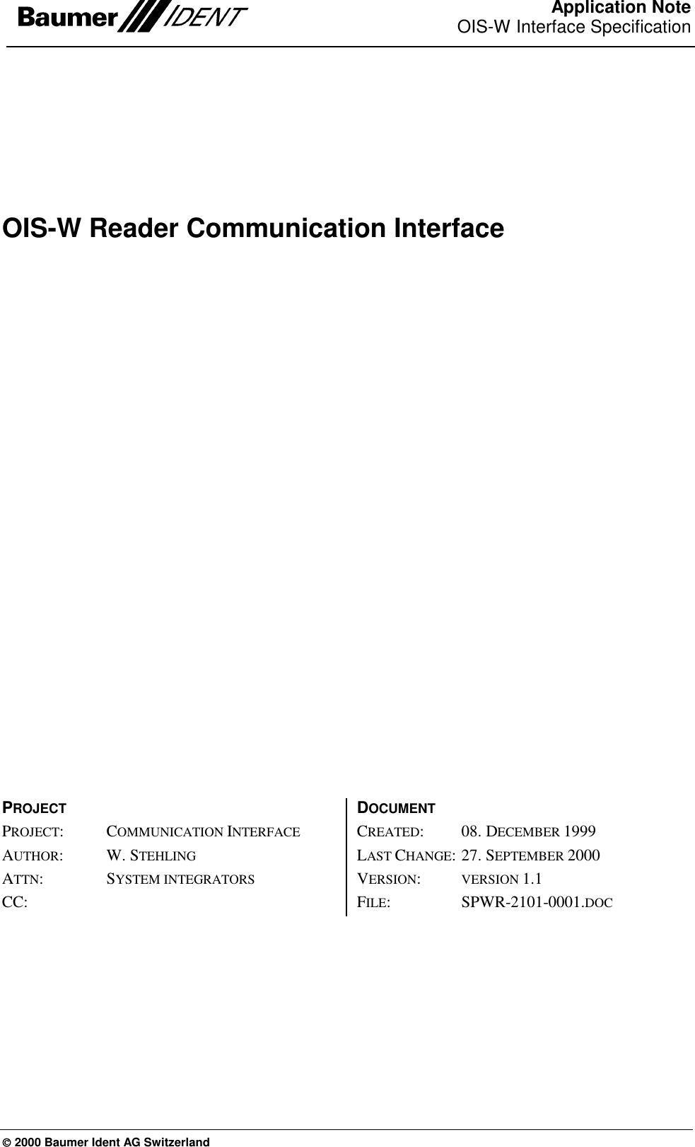
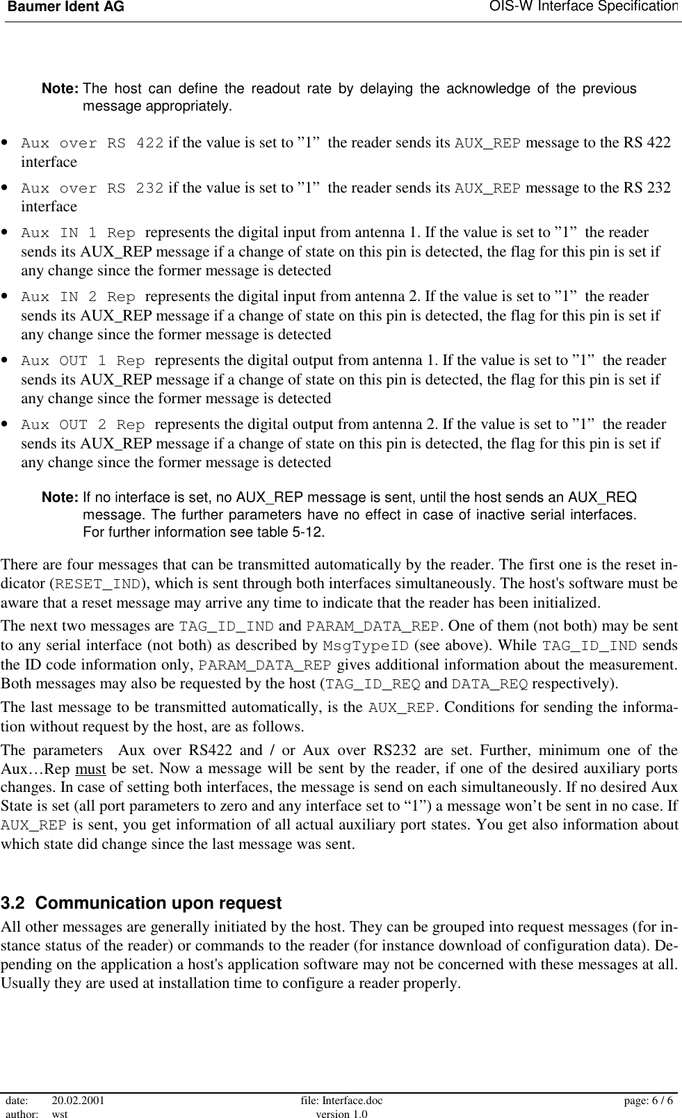
![Baumer Ident AG OIS-W Interface Specification date: 20.02.2001 author: wst file: Interface.doc version 1.0 page: 5 / 5 3 Reader operating modes Basically, the reader may operate in one of two main modes: triggered or free running. In triggered mode a new measurement starts as soon as an external signal is supplied or a trigger message from the host is received. In free running mode the reader is looking continuously for a valid identification. An identification message (or an appropriate error message in triggered mode) can be sent to a host in two ways: automatically or on request by the host. Usually, the automatic ID data message is sufficient in most applications. The functionality of the reader is controlled by a configuration file that allows setting of all parameters. Figure 3-1 shows the part of the configuration file dealing with the communication. The other parts of the file are not subject of this documentation. For further details see [2]. // BAUMER IDENT SAW tag reader STAR2 // configuration data // date: 09.06.1999 // time: 10:03:45 // settings serial interface Bdrate RS422 1152 Baud rate RS422 IF [ 12.. 1152] Bdrate RS232 1152 Baud rate RS232 IF [ 12.. 1152] Msg Type ID 11 select type of notification after successful reading [ 0.. 19] TidF 2 s time const ID filter (res:.5s) [0.5..32767] ID Msg Retry 2 max. number transmissions of ID Msg(0=no maximum) [ 0.. 255] ID Msg Timeout 2 s time until ID msg is retransmitted (res:0.5s, 0=no limit) [ 0..127.5] // settings auxiliary ports : : : : Aux over RS 422 0 choose RS422 interface for Aux State Indication message (0 = OFF; 1 = ON) [ 0.. 1] Aux over RS 232 0 choose RS232 interface for Aux State Indication message (0 = OFF; 1 = ON) [ 0.. 1] Aux IN 1 Rep 1 Aux State Indication mask (0 = OFF; 1 = ON) [ 0.. 1] Aux IN 2 Rep 1 Aux State Indication mask (0 = OFF; 1 = ON) [ 0.. 1] Aux OUT 1 Rep 1 Aux State Indication mask (0 = OFF; 1 = ON) [ 0.. 1] Aux OUT 2 Rep 1 Aux State Indication mask (0 = OFF; 1 = ON) [ 0.. 1] Figure 3-1: The section of the reader configuration file dealing with communication 3.1 Automatic Data Transmission Several parameters of the configuration file describe the automatic messaging (Figure 3-1): • The MsgTypeID entry of the configuration file defines the way how and where an automatic ID message will be sent. The first digit designates the interface (0: RS 422, 1: RS 232), the second digit indicates the message type (0: no message, 1: TAG_ID_IND, 2: PARAM_DATA). The message details will be explained below. • TidF is a filter time constant. The same message is sent again after this time has elapsed, if the same ID code is detected repeatedly. • IDMsgRetry gives the number of repetitions the message will be transmitted, if the host does not acknowledge the telegram. The parameter is set to 0, if an acknowledge is mandatory; it is set to 1, if an acknowledge might be missing. • IDMsgTimeout is the time to wait for acknowledge between the repetitions.](https://usermanual.wiki/Baumer-Electric/OIS-W-WR300303.Interface/User-Guide-141771-Page-5.png)
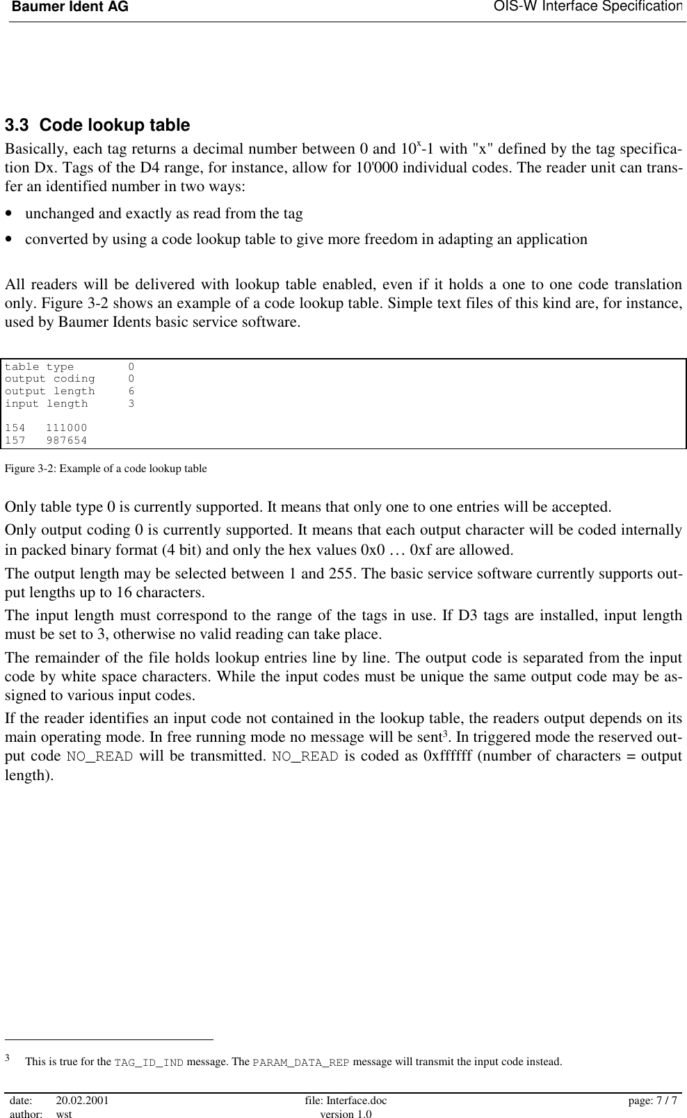
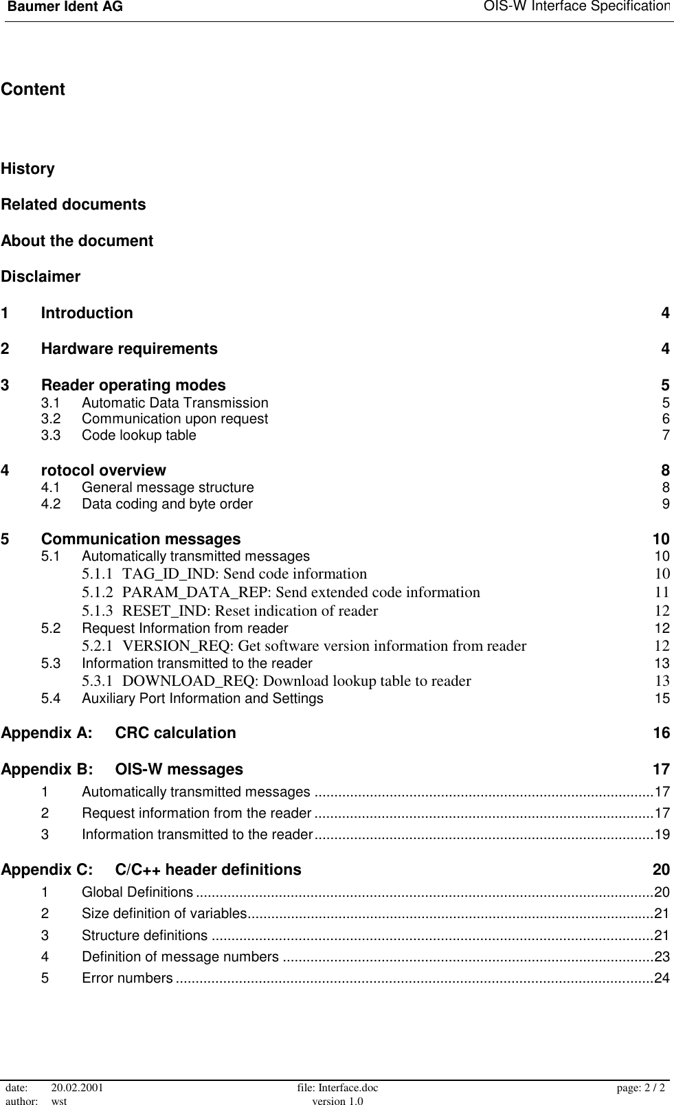
![Baumer Ident AG OIS-W Interface Specification date: 20.02.2001 author: wst file: Interface.doc version 1.0 page: 8 / 8 4 rotocol overview The communication protocol is similar to the Siemens 3964R protocol. 4.1 General message structure The general structure of a message is shown in Table 4-1. Following the START byte the MSG_NR indi-cates unambiguously the message. The next two bytes hold the length of an optional data array (high and low byte of a 16-bit number respectively). The message ends with a checksum byte and an END of mes-sage indicator. The checksum is calculated over all bytes except START, CRC and END. The calculation of the cyclic redundancy check is detailed in appendix 0. The data fields are optional and may be omit-ted. byte offset message bytes comment 0 START = 0x02 start of message indicator 1 MSG_NR message number 2 HI MSG_LEN high byte message length Cyclic 3 LO MSG_LEN low byte message length Redundancy 4 [DATA (0)] first data byte [optional] check 3 + MSG_LEN [DATA (MSG_LEN-1)] last data byte [optional] CRC 4 + MSG_LEN ~CRC logically inverted CRC checksum 5 + MSG_LEN END = 0x03 end of message indicator Table 4-1: General structure of a message Usually, a message sent by the reader or by the host must be acknowledged by the other one. The reader may be configured to repeat an automatic message a number of times, if the acknowledge is missing (see chapter 3.1). Two forms of acknowledge messages are possible depending on the type of the primary message: • Often a general acknowledge message type as shown in Table 4-2 will be used. The host replies in this way to automatically transmitted messages. The same type of acknowledge is sent in most cases by the reader as reply to commands from the host. • On requests of the host the reader answers with an explicit reply message. An additional acknowledge will not be sent, neither by the host nor by the reader.](https://usermanual.wiki/Baumer-Electric/OIS-W-WR300303.Interface/User-Guide-141771-Page-8.png)
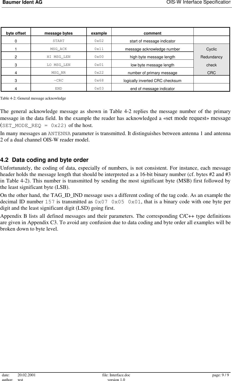
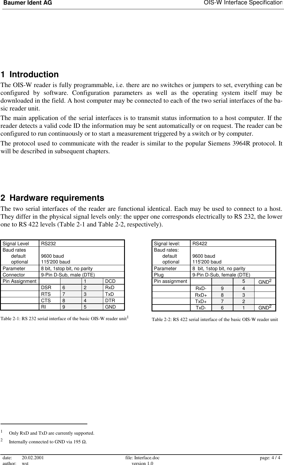
![Baumer Ident AG OIS-W Interface Specification date: 20.02.2001 author: wst file: Interface.doc version 1.0 page: 10 / 10 5 Communication messages This chapter gives typical examples of the most important messages in full detail. A complete list of all messages is given in appendix Appendix B: . Table 5-1 shows the definitions used to describe the basic data type sizes (cf. Appendix C2). type description size range type description size range UINT8 unsigned byte 1 byte 0 … 255 INT8 signed byte 1 byte -128 … 127 UINT16 unsigned word 2 byte 0 … 65'535 INT16 signed word 2 byte -32'768 … 32'767 UINT32 unsigned long 4 byte 0 … 4'294'967'295 INT32 signed long 4 byte -2'147'483'648 … 2'147'483'647 Table 5-1: Data size definitions 5.1 Automatically transmitted messages 5.1.1 TAG_ID_IND: Send code information This message is a short version of PARAM_DATA_REP. byte variable basic type example comment 0 START UINT8 0x02 start of message indicator 1 MSG_NR UINT8 0x50 TAG_ID_IND message 2 HI_MSG_LEN UINT16 0x00 length of data field 3 LO_MSG_LEN 0x04 4 bytes to transmit 4 ANTENNA UINT8 0x01 channel number (ANT_1 = 1, ANT_2 = 2) 5 LO_ID UINT8 [length-1] 0x07 least significant digit of ID code 6 … 0x05 (example code = 157) 7 HI_ID 0x01 8 ~CRC UINT8 0x42 logically inverted CRC 9 END UINT8 0x03 end of message indicator Table 5-2: Automatically transmitted tag ID message from the reader Note: This message is of variable length. The ID may have up to 16 digits. Therefore the message length is limited to 2 ≤ length ≤ 17. byte variable basic type example comment 0 START UINT8 0x02 start of message indicator 1 MSG_NR UINT8 0x11 MSG_ACK message 2 HI_MSG_LEN UINT16 0x00 length of data field 3 LO_MSG_LEN 0x01 1 byte to transmit 4 MSG_NR UINT8 0x50 message to acknowledge: TAG_ID_IND 5 ~CRC UINT8 0x5c logically inverted CRC 6 END UINT8 0x03 end of message indicator Table 5-3: Acknowledge of TAG_ID_IND message from the host](https://usermanual.wiki/Baumer-Electric/OIS-W-WR300303.Interface/User-Guide-141771-Page-10.png)
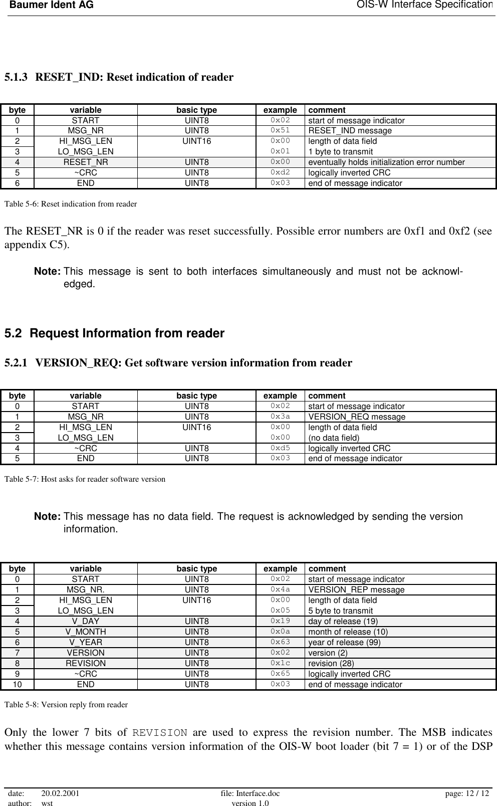
![Baumer Ident AG OIS-W Interface Specification date: 20.02.2001 author: wst file: Interface.doc version 1.0 page: 11 / 11 5.1.2 PARAM_DATA_REP: Send extended code information byte variable basic type example comment 0 START UINT8 0x02 start of message indicator 1 MSG_NR UINT8 0x45 PARAM_DATA_REP message 2 HI_MSG_LEN UINT16 0x00 length of data field 3 LO_MSG_LEN 0x39 57 bytes to transmit 4 INVALID UINT8 0x01 set to 1 if data are invalid 5 LO_ID UINT8 [CODE_MAX_LEN] 0x07 least significant digit of ID code 6 … 0x05 (example code = 157) 7 … 0x01 8 … 0xff unused bytes are filled with 0xff … … … 20 HI_ID 0xff 21 AF_AGC UINT8 0x00 automatic gain control 22 NOISE_LEVEL UINT8 0x20 maximum noise level in spectrum 23 CAL_MAGNITUDE UINT8 0x48 signal strength of calibrator (in 0.5 dBr) 24 CAL_SHIFT INT8 0x01 description of tag properties 25 FIRST_TAP_POS UINT8 0x3d 26 DELTA_LAST_TAP_POS UINT8 0x36 27 ANTENNA UINT8 0x01 channel number (ANT_1 = 1, ANT_2 = 2) 28 BLOC UINT8 [CODE_MAX_LEN+1] 0x00 description of tag properties … … … … 44 … … 0x00 45 BLOC_MAGNITUDE UINT8 [CODE_MAX_LEN] 0x46 signal strength of code blocs (in 0.5 dBr) 46 … 0x46 i.e. 0x46 hex → 70 decimal → 35 dBr 47 … 0x48 48 … 0x00 ignore unused blocs (set to 0) … … … 60 … 0x00 61 ~CRC UINT8 0xda logically inverted CRC 62 END UINT8 0x03 end of message indicator Table 5-4: Parameter data reply message The interesting data fields are CAL_MAGNITUDE and BLOC_MAGNITUDE that give an idea of the re-ceived signal strengths. Note: This message uses fixed length records. Unused bytes are filled appropriately. byte variable basic type example comment 0 START UINT8 0x02 start of message indicator 1 MSG_NR UINT8 0x11 MSG_ACK message 2 HI_MSG_LEN UINT16 0x00 length of data field 3 LO_MSG_LEN 0x01 1 byte to transmit 4 MSG_NR UINT8 0x45 message to acknowledge: PARAM_DATA_REP 5 ~CRC UINT8 0xff logically inverted CRC 6 END UINT8 0x03 end of message indicator Table 5-5: Acknowledge of PARAM_DATA_REP message from the host](https://usermanual.wiki/Baumer-Electric/OIS-W-WR300303.Interface/User-Guide-141771-Page-11.png)
![Baumer Ident AG OIS-W Interface Specification date: 20.02.2001 author: wst file: Interface.doc version 1.0 page: 13 / 13 operating system (bit 7 = 0). The boot loader does only respond if the DSP cannot find a valid program to execute following reset or power up. 5.3 Information transmitted to the reader 5.3.1 DOWNLOAD_REQ: Download lookup table to reader The download request is a fixed length message that is used to transmit DSP software (type = 0), ramp controller software (type = 1), or a lookup table (type = 2). The data array is broken into blocks of size DOWNLOAD_MSG_SIZE byte each (currently set to 32). Unused bytes are filled appropriately. byte variable basic type example comment 0 START UINT8 0x02 start of message indicator 1 MSG_NR UINT8 0x10 DOWNLOAD_REQ message 2 HI_MSG_LEN UINT16 0x00 length of data field 3 LO_MSG_LEN 0x25 fixed length: 37 byte to transmit 4 TYPE UINT8 0x02 download lookup table (type = 2) 5 LO_BLOCKS UINT16 0x02 total number of blocks to transmit 6 HI_BLOCKS 0x00 7 LO_BLOCK_NR. UINT16 0x01 number of blocks that will follow this message 8 HI_BLOCK_NR. 0x00 9 MAGIC_WORD UINT8[16] 0x63 c 10 0x6f o 11 0x64 d 12 0x65 e 13 0x20 space 14 0x74 t 15 0x61 a 16 0x62 b 17 0x6c l 18 0x65 e 19 0x20 space 20 0x70 p 21 0x63 c 22 0x20 space 23 0x20 space 24 0x20 space 25 TABLE_TYPE UINT8 0x00 26 OUTPUT_CODING UINT8 0x00 27 OUTPUT_LENGTH UINT8 0x06 28 INPUT_LENGTH UINT8 0x03 29 LO_NUM_OF_ENTRIES UINT32 0x02 number of entries in table 30 | 0x00 31 | 0x00 32 HI_NUM_OF_ENTRIES 0x00 33 0x00 fill bytes set to 0 … … 40 0x00 41 ~CRC UINT8 0x1c logically inverted CRC 42 END UINT8 0x03 end of message indicator Table 5-9: Download lookup table to reader. The first block describes the table parameters. The first block transmitted contains the table parameters as described in chapter 3.3. The example corre-sponds to Figure 3-2. Note: UINT16 and UINT32 values in the data field use a different byte order than the mes-sage length field.](https://usermanual.wiki/Baumer-Electric/OIS-W-WR300303.Interface/User-Guide-141771-Page-13.png)
![Baumer Ident AG OIS-W Interface Specification date: 20.02.2001 author: wst file: Interface.doc version 1.0 page: 14 / 14 The reader responds with a download reply message that echoes the TYPE field: byte variable basic type example comment 0 START UINT8 0x02 start of message indicator 1 MSG_NR UINT8 0x15 DOWNLOAD_REP message 2 HI_MSG_LEN UINT16 0x00 length of data field 3 LO_MSG_LEN 0x01 1 byte to transmit 4 TYPE UINT8 0x02 reply to lookup table download (type = 2) 5 ~CRC UINT8 0x09 logically inverted CRC 6 END UINT8 0x03 end of message indicator Table 5-10: Download reply message from reader. The next block(s) transmit the actual lookup table entries: byte variable basic type example comment 0 START UINT8 0x02 start of message indicator 1 MSG_NR UINT8 0x10 DOWNLOAD_REQ message 2 HI_MSG_LEN UINT16 0x00 length of data field 3 LO_MSG_LEN 0x25 fixed length: 37 byte to transmit 4 TYPE UINT8 0x02 download lookup table (type = 2) 5 LO_BLOCKS UINT16 0x02 total number of blocks to transmit 6 HI_BLOCKS 0x00 7 LO_BLOCK_NR. UINT16 0x00 number of blocks that will follow this message 8 HI_BLOCK_NR 0x00 9 PACKED_DATA UINT8 0x45 packed binary (4 bit per digit), least significant 10 [DOWNLOAD_MSG_SIZE] 0x10 nibble goes first: 11 0x00 451 000111 751 456789 12 0x11 13 0x17 should be interpreted as: 14 0x51 154 111000 15 0x45 157 987654 16 0x67 17 0x89 18 0x00 unused nibbles set to 0 … … 40 0x00 41 ~CRC UINT8 0x97 logically inverted CRC 42 END UINT8 0x03 end of message indicator Table 5-11: Download lookup table to reader. The remaining blocks transmit the table entries in packed form. The reader acknowledges using again the message shown in Table 5-10.](https://usermanual.wiki/Baumer-Electric/OIS-W-WR300303.Interface/User-Guide-141771-Page-14.png)
![Baumer Ident AG OIS-W Interface Specification date: 20.02.2001 author: wst file: Interface.doc version 1.0 page: 16 / 16 Appendix A: CRC calculation The CRC polynomial is x7 + x3 + 1. CRC is calculated over the MSG_NR, MSG_LEN and DATA fields, "~CRC" means that the calculated CRC byte is transmitted as the ones-complement (bit wise negated). The DATA field is optional as some messages do not contain data. The message length is equal to the number of bytes in the data field. Figure A-1 shows a subroutine to calculate CRC using a lookup table. This is a fast method for speed critical applications. Figure A-2 shows a subroutine to calculate CRC in the classical way. Figure A-3 shows an example how to calculate CRC of a message. void Msg_CRC(UINT8 in, INT16* state) /*--------------------------------------------------------------------------+ | Description: | | | | Does 8-bit cyclic redundancy check on one data byte | | CRC polynomial is x^7 + x^3 + 1 | | Returns the current state | +--------------------------------------------------------------------------*/ { static const crc_tab[16] = { 0, 18, 36, 54, 72, 90, 108, 126, 144, 130, 180, 166, 216, 202, 252, 238}; *state = crc_tab[(*state ^ in) & 0xF] ^ (*state >> 4); in >>= 4; *state = crc_tab[(*state ^ in) & 0xF] ^ (*state >> 4); } Figure A-1: CRC calculation using a lookup table void Msg_CRC(unsigned char in, int* state) /*--------------------------------------------------------------------------+ | Description: | | | | Does 8-bit cyclic redundancy check on one data byte | | CRC polynomial is x^7 + x^3 + 1 | | Returns the current state | +--------------------------------------------------------------------------*/ { #define CRC_POLYN 0x120 //Note that MSB is state input (0x90 << 1) INT16 j; for (j = 0; j < 8; j++) { if ((*state ^ in) & 1) *state ^= CRC_POLYN; in >>= 1; *state >>= 1; } } Figure A-2: CRC calculation using algorithm void Calc_CRC() { INT16 crc=0; // state register of CRC Msg_CRC(MSG_NR,&crc); Msg_CRC(HI_MSG_LEN,&crc); Msg_CRC(LO_MSG_LEN,&crc); Msg_CRC(DATA_BYTE[0],&crc); // ... Msg_CRC(DATA_BYTE[N-1],&crc); // CRC checksum is now contained in crc crc = ~crc; // logically invert } Figure A-3: Application example for CRC calculation](https://usermanual.wiki/Baumer-Electric/OIS-W-WR300303.Interface/User-Guide-141771-Page-16.png)
![Baumer Ident AG OIS-W Interface Specification date: 20.02.2001 author: wst file: Interface.doc version 1.0 page: 17 / 17 Appendix B: OIS-W messages In the following descriptions only the message number MSG_NR and the data field(s) are listed. Start byte, length, CRC and end byte must be added to get the full message (see Table 4-1 for complete mes-sage structure). The initiator message is listed on the first lines followed by the response. The identifiers are defined in appendix Appendix C: . 1 Automatically transmitted messages from host from reader comment TAG_ID_IND UINT8 antenna UINT8 id[tlen] tag identification number and the antenna where it is received tlen = length of Tag or length of output code in code table MSG_ACK UINT8 msg_nr general message acknowledge on message msg_nr (msg_nr = TAG_ID_IND) PARAM_DATA_REP struct TINFO tag_info tag identification number, antenna and further information about the tag MSG_ACK UINT8 msg_nr general message acknowledge on message msg_nr (msg_nr = TAG_ID_IND) AUX_REP struct AUX aux_status contains present aux port settings MSG_ACK UINT8 msg_nr✠ general message acknowledge on message msg_nr (msg_nr = AUX_REP) RESET_IND UINT8 reset_nr contains number for possible error during initialization, zero on success Note that the RESET_IND is sent to both interfaces at the same time! Table B-12: Automatically transmitted messages by the reader The reader can be configured to send either a TAG_ID_IND message or a PARAM_DATA_REP message automatically. The RESET_IND message is always sent by the reader after a successful initialization. Please note that no acknowledge for RESET_IND is expected. 2 Request information from the reader A host can get information from the reader as described in Table B-13. Please note that the automatic PARAM_DATA_REP (Table B-12) leads to the same message as the reply to a DATA_REQ with parame-ter PARAM_DATA_REP. ✠ MSG_ACK is optional, but flags for actual state change report will not be reset when an acknowledge on an AUX_REP message isn’t send](https://usermanual.wiki/Baumer-Electric/OIS-W-WR300303.Interface/User-Guide-141771-Page-17.png)
![Baumer Ident AG OIS-W Interface Specification date: 20.02.2001 author: wst file: Interface.doc version 1.0 page: 18 / 18 from host from reader comment VERSION_REQ Ask for SW Version VERSION_REP UINT8 version [5] Reply SW version number and release date CONFIG_REQ get tag structure and reader configuration CONFIG_REP struct CONFIG act_conf contains requested configuration SER_CONFIG_REQ get interface configuration SER_CONFIG_REP struct SER_CONFIG act_conf contains requested configuration AUX_REQ get present state of aux port AUX_REP struct AUX aux_status contains present aux port settings MODE_REQ get present main mode and sub-modes MODE_REP UINT8 main UINT8 tx_untriggered UINT8 biased UINT8 synch UINT8 random UINT8 Tm UINT8 Nmess UINT8 Tdmin[2] UINT8 Tdlen[2] UINT8 Tsleep[2] UINT8[CODE_MAX_LEN]biased_id UINT8[CODE_MAX_LEN]analyz_id UINT8 CwChannel UINT8 TxEnable contains present mode, sub modes, biased id number, analyze id number, settings for Test mode random = 0: random mode off, 1: random mode on Tm: number of iterations in trigger loop Nmess: number of measurements in Random triggered mode Tdmin, Tdlen, Tsleep: initial delay, random time, sleep time in random mode CwChannel = 0: Test mode off, 2..81: valid continuous wave channel TxEnable = 0: transmitter in test off, 1: transmit antenna 1, 2: transmit antenna 2 CODE_PP_REQ request installation and family code CODE_PP_REP PP_SETTINGS codes actual installation and family code AUX_CONFIG_REQ request output port configuration AUX_CONFIG_REP AUXALL_CONFIG[2] aux_config actual output port configuration TAG_ID_REQ get last valid ID TAG_ID_IND UINT8 code.antenna UINT8code.num[CODE_MAX_LEN] last valid tag id at antenna 1 or 2 In case there has never been received a valid tag id, the reader responses with a data field containing NO_READ IF_ERROR_REQ request interface errors of both interfaces IF_ERROR_REP UINT32 [if_error_array] Errors on both interfaces, cumulative counting DATA_REQ get data vector: time, frequency, save or/and parameter UINT8 data_msg TIME_DATA_REP INT8[SBUF_LEN] or/and SAVE_DATA_REP INT16 SBUF_LEN INT16[SBUF_LEN] INT16 PARAM_LEN INT16 AF_AGC INT16 ANTENNA or/and FREQ_DATA_REP UINT8[ABUF_LEN] or/and PARAM_DATA_REP struct TINFO tag_info contains data time vector, data save vector, data freq vector or data param vector (1 up to 3 messages can be received according to the data_msg value in DATA_REQ) TINFO contains information on Valid/Invalid tag, Tag ID num-ber, Tag Errors during detection, Antenna information, AF at-tenuation (AGC) values CODE_TABLE_REQ Upload complete postprocessing code table UINT8 block_nr CODE_TABLE_REP UINT16 blocks UINT16 block_nr UINT8[DOWNLOAD_MSG_SIZE] Blockwise request of code table addressed by block_nr ANALYZ_RESULT_REQ get analyze mode results ANALYZ_RESULT_REP struct ANALYZ contains analyze mode results ERROR_ARRAY_REQ get error array ERROR_ARRAY_REP UINT8 error_array[ERR_MAX] contains error array, every position of error_array despite posi-tion zero contains a counter that indicates how many times the error has occurred since the last reset Table B-13: Messages that request information from the reader](https://usermanual.wiki/Baumer-Electric/OIS-W-WR300303.Interface/User-Guide-141771-Page-18.png)
![Baumer Ident AG OIS-W Interface Specification date: 20.02.2001 author: wst file: Interface.doc version 1.0 page: 19 / 19 3 Information transmitted to the reader from host from reader meaning SET_CONFIG_REQ set tag structure and reader configuration parameter(s) struct CONFIG new_conf MSG_ACK UINT8 msg_nr general message acknowledge msg_nr = SET_CONFIG_REQ SET_SER_CONFIG_REQ set interface configuration parameter(s) struct SER_CONFIG new_conf MSG_ACK UINT8 msg_nr general message acknowledge msg_nr = SET_SER_CONFIG_REQ SET_AUX_REQ set aux port UINT8 aux_out MSG_ACK UINT8 msg_nr general message acknowledge msg_nr = SET_AUX_REQ SET_MODE_REQ UINT8 main UINT8 tx_untriggered UINT8 biased UINT8 sync UINT8 random UINT8 Tm UINT8 Nmess UINT8 Tdmin[2] set main mode and sub-modes UINT8 Tdlen[2] UINT8 Tsleep[2] MSG_ACK UINT8 msg_nr general message acknowledge msg_nr = SET_MODE_REQ SET_BIASED_ID_REQ set id for biased mode UINT8[CODE_MAX_LEN] biased_id MSG_ACK UINT8 msg_nr general message acknowledge msg_nr = SET_BIASED_ID_REQ SET_TRIGGER_REQ UINT8 antenna triggers reader (SW trigger) antenna = 1, trigger antenna 1 antenna = 2, trigger antenna 2 antenna = 3, tirgger both antennas MSG_ACK UINT8 msg_nr general message acknowledge msg_nr = SET_TRIGGER_REQ SET_CODE_PP_REQ set installation and family code PP_SETTINGS codes MSG_ACK UINT8 msg_nr general message acknowledge msg_nr = SET_CODE_PP_REQ SET_AUX_TRIG_REQ Host trigger output AOUT1 or AOUT2 UINT8 aux_host_trigger MSG_ACK UINT8 msg_nr general message acknowledge msg_nr = SET_AUX_TRIG_REQ SET_AUX_CONFIG_REQ set output port configuration for AOUT1 and AOUT2 as for the in-formation about the complete auxiliary port ; resets aux flags AUXALL_CONFIG[2] aux_config MSG_ACK UINT8 msg_nr general message acknowledge msg_nr = SET_AUX_CONFIG_REQ SET_ANALYZ_ID_REQ set id for analyze mode and reset counter UINT8[CODE_MAX_LEN] MSG_ACK UINT8 msg_nr general message acknowledge msg_nr = SET_ANALYZ_ID_REQ DOWNLOAD_REQ UINT8 type UINT16 blocks UINT16 block_nr UINT8[DOWNLOAD_MSG_SIZE] contains new downloadable file DOWNLOAD_MSG_SIZE=32 possible types are DSP_SW=0, FPGA_SW=1, CODE_TABLE=2 after reception of the all blocks an automatic reset is issued for DSP_SW and FPGA_SW, block_nr counts from blocks-1 down to zero DOWNLOAD_REP UINT8 type acknowledge for each block SET_TEST_REQ UINT8 cw_channel UINT8 tx_enable enters or leaves test mode CwChannel = 0 leaves test mode; CwChannel = 2..81 enters test mode, TxEnable = 0: TX off, 1: antenna 1 on, 2: antenna 2 on MSG_ACK UINT8 msg_nr general message acknowledge msg_nr = SET_TEST_REQ SET_MONITOR_REQ UINT8 antenna UINT8 beeper Sets Display filter in antenna alternating mode, sends only DATA_REP messages from ANT_1 or ANT_2 or both antennas (default). Beeper can be enabled =1, beeps on every valid tag ID. This setting is volatile, after reset the default setting is assumed. MSG_ACK UINT8 msg_nr general message acknowledge msg_nr = SET_DISPLAY_REQ RESET_REQ reset DSP SW RESET_IND UINT8 reset_nr contains number for possible error during initialization, zero on success Table B-14: Messages that the host may send to the reader](https://usermanual.wiki/Baumer-Electric/OIS-W-WR300303.Interface/User-Guide-141771-Page-19.png)
![Baumer Ident AG OIS-W Interface Specification date: 20.02.2001 author: wst file: Interface.doc version 1.0 page: 21 / 21 2 Size definition of variables /*** Size Definition of Variables ***/ typedef unsigned char UINT8; typedef unsigned int UINT16; typedef unsigned long UINT32; typedef char INT8; typedef int INT16; typedef long INT32; 3 Structure definitions /*** structure definitions ***/ typedef struct { UINT8 *start; INT16 len; volatile in; volatile out; } BUFOBJ; typedef enum { RAND_OFF, RAND_TD_MIN, RAND_GENERATE, RAND_RUN, RAND_SLEEP } RANDOM_STATE; typedef enum { TRIG_OFF, TRIG_PREP, TRIG_IND, TRIG_IND1, TRIG_RUN } TRIG_STATE; typedef struct { UINT8 flag; float array[ABUF_LEN]; } ABUF; typedef struct { UINT32 Total_ids; UINT32 Invalid_ids; UINT32 Wrong_but_valid_ids;} ANALYZ; typedef struct { UINT8 aux_chinden; UINT8 aux_chindmsk; } AUXCHIND_CONFIG; typedef struct { UINT8 aux_mode; UINT8 aux_function; UINT8 aux_inv; UINT8 aux_tdon; UINT8 aux_tdoff; UINT8 aux_tauxf[2]; } AUX_CONFIG; typedef struct { UINT8 aux_in; UINT8 aux_out; UINT8 aux_sync_in; UINT8 aux_sync_out; UINT8 aux_flag; UINT8 aux_in_trig; UINT8 aux_sync_trig; UINT8 aux_random_trig; } AUX; typedef struct { AUX_CONFIG port[2]; AUXCHIND_CONFIG auxchind_cfg;} AUXALL_CONFIG; typedef struct { UINT8 antenna; UINT8 num[CODE_MAX_LEN];} CODE;](https://usermanual.wiki/Baumer-Electric/OIS-W-WR300303.Interface/User-Guide-141771-Page-21.png)
![Baumer Ident AG OIS-W Interface Specification date: 20.02.2001 author: wst file: Interface.doc version 1.0 page: 22 / 22 typedef struct { UINT8 Tslot; UINT8 Ncodebloc; UINT8 Ncodeslot; UINT8 Ncalrefl; UINT8 Ncoderef; UINT8 Ncheckrefl; UINT8 Nextrefl; UINT8 Nmesrefl; UINT8 Tcode00[2]; INT8 Tcal; UINT8 Nnoisebin; UINT8 Tmes0[2]; UINT8 Puseguard; UINT8 Channel; UINT8 Ant; UINT8 Navg[2]; UINT8 Na; UINT8 Nequ; UINT8 Pposinst; UINT8 Ninst; UINT8 Pposfam; UINT8 Nfam; UINT8 Pposuser; UINT8 Nuser; UINT8 Ntab; UINT8 Afagc; UINT8 SNR; UINT8 DSNRCal; UINT8 DMultiTag; UINT8 InitDelay1; UINT8 InitDelay2; UINT8 DelayRange1; UINT8 DelayRange2; } CONFIG; typedef struct { UINT8 message; UINT8 data_msg; UINT8 interface; INT16 length; BUFOBJ *buf; } DS_MSG; typedef struct { BUFOBJ si_rx; BUFOBJ si_tx; BUFOBJ da_rx; BUFOBJ da_tx; } DS_PTR; typedef struct { UINT8 main; UINT8 tx_untriggered; UINT8 biased; UINT8 sync; UINT8 random; UINT8 Tm; UINT8 Nmess; UINT8 Tdmin[2]; UINT8 Tdlen[2]; UINT8 Tsleep[2]; UINT8 analyz_id[CODE_MAX_LEN]; UINT8 biased_id[CODE_MAX_LEN]; UINT8 CwChannel; UINT8 TxEnable; } MODE; typedef struct { UINT8 Instal_code_len; UINT8 Table_lookup_On; UINT8 Family_code_len; UINT8 Instal_code[CODE_MAX_LEN]; UINT8 Family_code[CODE_MAX_LEN];} PP_SETTINGS; typedef struct { UINT8 flag; INT16 array[SBUF_LEN]; UINT8 Afagc; UINT8 antenna; } SBUF; typedef struct { UINT8 SerSpeedDA; UINT8 SerSpeedSI; UINT8 MsgTypeID; UINT8 TidF[2]; UINT8 ID_Msg_Retry; UINT8 ID_Msg_Timeout; } SER_CONFIG;](https://usermanual.wiki/Baumer-Electric/OIS-W-WR300303.Interface/User-Guide-141771-Page-22.png)
![Baumer Ident AG OIS-W Interface Specification date: 20.02.2001 author: wst file: Interface.doc version 1.0 page: 23 / 23 typedef struct { UINT8 Invalid; UINT8 Num[CODE_MAX_LEN]; UINT8 AF_Agc; UINT8 Noise_Level; UINT8 Cal_Magnitude; INT8 Cal_Shift; UINT8 First_Tap_Pos; UINT8 Delta_Last_Tap_Pos; UINT8 Cur_Ant; UINT8 Bloc[CODE_MAX_LEN1]; UINT8 Bloc_Magnitude[CODE_MAX_LEN];} TINFO; typedef struct { TINFO tag[ID_FIFO_LEN]; CODE data[ID_FIFO_LEN]; INT16 in_idx; INT16 out_idx; } TJD_FIFO; typedef struct { TRIG_STATE state; INT16 count[2]; RANDOM_STATE rnd; INT16 meas_count; } TRIGGER; 4 Definition of message numbers /*** definition of message numbers ***/ #define DOWNLOAD_REQ 0x10 #define MSG_ACK 0x11 #define RESET_REQ 0x12 #define TEST_SER_REQ 0x13 #define TEST_SER_REP 0x14 #define DOWNLOAD_REP 0x15 #define SET_CONFIG_REQ 0x20 #define SET_AUX_REQ 0x21 #define SET_MODE_REQ 0x22 #define SET_TRIGGER_REQ 0x23 #define SET_ANALYZ_ID_REQ 0x25 #define SET_BIASED_ID_REQ 0x26 #define SET_TEST_REQ 0x27 #define SET_CODEPP_REQ 0x28 #define SET_MONITOR_REQ 0x29 #define SET_AUX_CONFIG_REQ 0x2A #define SET_AUX_TRIG_REQ 0x2B #define SET_ADDR_REQ 0x2C // not handled by DSP SW #define SET_SER_CONFIG_REQ 0x2D #define CONFIG_REQ 0x30 #define AUX_REQ 0x31 #define MODE_REQ 0x32 #define DATA_REQ 0x33 #define TAG_ID_REQ 0x34 // response TAG_ID_IND #define ANALYZ_RESULT_REQ 0x37 #define CODE_TABLE_REQ 0x38 #define ERROR_ARRAY_REQ 0x39 #define VERSION_REQ 0x3A #define CODEPP_REQ 0x3B #define IF_ERROR_REQ 0x3C #define AUX_CONFIG_REQ 0x3D #define SER_CONFIG_REQ 0x3E](https://usermanual.wiki/Baumer-Electric/OIS-W-WR300303.Interface/User-Guide-141771-Page-23.png)