Beautiful Enterprise SFQ04A Bluetooth Module User Manual update
Beautiful Enterprise Co., Ltd. Bluetooth Module update
UserManual.wiki
>
Beautiful Enterprise
>
SFQ04A User Manual
Users Manual
Navigation menu
Upload a User Manual
Namespaces
Wiki Guide
HTML
PDF
Info
Views
User Manual
Discussion / Help
Navigation
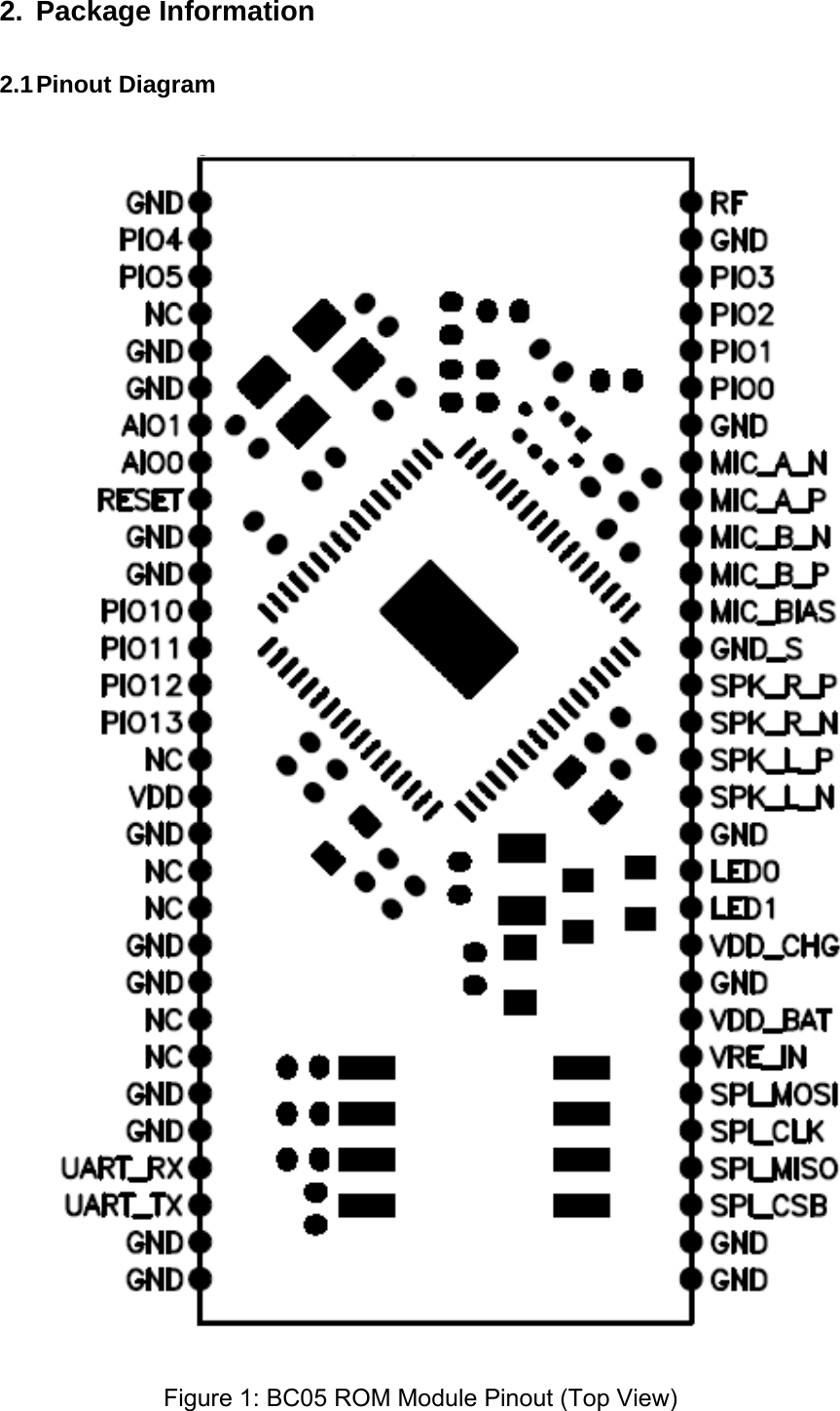
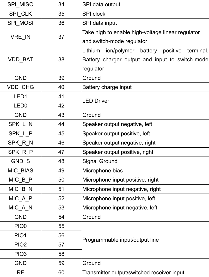
![2.2 Terminal Functions Pin Name Pin Number Description GND 1 Ground PIO4 2 PIO5 3 Programmable input/output line NC 4 NC GND 5 Ground GND 6 Ground AIO1 7 AIO0 8 Analogue programmable input/output line RESET 9 System Reset(Low Active) GND 10 Ground GND 11 Ground PIO10 12 PIO11 13 PIO12 14 PIO13 15 Programmable input/output line NC 16 NC VDD 17 Positive supply for SPI/UART ports and PIO[13:10] &PIO[5:0] and EEPROM, Connect to 3.3V GND 18 Ground NC 19 NC NC 20 NC GND 21 Ground GND 22 Ground NC 23 NC NC 24 NC GND 25 Ground GND 26 Ground UART_RX 27 UART data input, active high UART_TX 28 UART data output, active high GND 29 Ground GND 30 Ground GND 31 Ground GND 32 Ground SPI_CSB 33 Chip select for SPI, active low](https://usermanual.wiki/Beautiful-Enterprise/SFQ04A/User-Guide-1996507-Page-5.png)