Bendix Commercial Vehicle Systems RX433-RV-1 Tire Monitoring System-Display Receiver User Manual 710 xxxx 1 0 RV owner
Bendix Commercial Vehicle Systems LLC Tire Monitoring System-Display Receiver 710 xxxx 1 0 RV owner
Contents
- 1. User Manual 1 of 3
- 2. User Manual 2 of 3
- 3. User Manual 3 of 3
User Manual 1 of 3

SmarTire Systems Inc.
Tire Monitor System Owner’s Manual Draft
2/25/2003 Page 1
This manual is under review by SmarTire
Tire Monitor System
Owner Manual
PN 710.xxxx
RV Tow-behind
Draft
Editors Notes
1. Application; North America, English
2. Prior to issue this manual to be examined and approved by;
a. Engineering
b. Marketing
c. Customer Service
3. Footnotes in this manual refer to the file names for the graphics. Original high resolution graphics are in
photoshop format and this manual uses jpg versions of the same graphics.

SmarTire Systems Inc.
Tire Monitor System Owner’s Manual Draft
2/25/2003 Page 2
This manual is under review by SmarTire
Table of Contents
Notices..............................................................................................................................................3
FCC Notice.................................................................................................................................................................................3
System Scope of Use and Warnings.....................................................................................................................................3
The SmarTire™ System and Tire Maintenance .............................................................................................................. 3
System Installation and Usage............................................................................................................................................ 3
Reacting to Alerts.................................................................................................................................................................. 3
Getting Started..................................................................................................................................4
Operation..........................................................................................................................................5
How It Works......................................................................................................................................................................... 5
Installation........................................................................................................................................6
Transmitter Installation ........................................................................................................................................................ 6
Tools Required ................................................................................................................................................................. 6
Installing Transmitter on a Wheel................................................................................................................................. 7
Mounting Tire with Transmitter on Wheel ................................................................................................................. 8
De-mounting the Tire with Transmitter Installed....................................................................................................... 9
Receiver PN 200.0087........................................................................................................................................................ 10
Full Function Display PN 200.0068 ................................................................................................................................ 11
Service and Warranty......................................................................................................................12
Component Part numbers................................................................................................................................................... 12
Troubleshooting................................................................................................................................................................... 13
System Default Settings..................................................................................................................................................... 13
Technical Specifications.................................................................................................................................................... 13
Strap Mount Transmitter .............................................................................................................................................. 13
Receiver........................................................................................................................................................................... 13
SmarTire Service Policy – Handling Returned Materials ............................................................................................ 13
US Warranty ........................................................................................................................................................................ 14
Appendix ........................................................................................................................................15
Glossary ................................................................................................................................................................................ 15

SmarTire Systems Inc.
Tire Monitor System Owner’s Manual Draft
2/25/2003 Page 3
This manual is under review by SmarTire
Notices
FCC Notice
This device complies with Part 15 of the FCC Rules. Operation is subject to the following two conditions: (1) this
device may not cause harmful interference, and (2) this device must accept any interference received, including
interference that may cause undesired operation.
This equipment has been tested and found to comply with the limits for a Class B digital device, pursuant to Part 15
of the FCC Rules. These limits are designed to provide reasonable protection against harmful interference in a
residential installation. This equipment generates, uses and can radiate radio frequency energy and, if not installed
and used in accordance with the instructions, may cause harmful interference to radio communications. However,
there is no guarantee that interference will not occur in a particular installation.
If this equipment does cause harmful interference to radio or television reception, which can be determined by
turning the equipment off and on, the user is encouraged to try to correct the interference by one or more of the
following measures:
• Reorient or relocate the receiving antenna.
• Increase the separation between the equipment and receiver.
• Connect the equipment into an outlet on a circuit different from that to which the receiver is connected.
• Consult the dealer or an experienced radio/TV technician for help.
Changes or modifications to this device without the express approval of SmarTire Systems Inc. may void the user’s
authority to use this device.
System Scope of Use and Warnings
The SmarTire™ System and Tire Maintenance
This system is a sensing device designed to identify and display tire operating data and activate an alert or warning
when pressure irregularities are detected. It is the responsibility of the driver to react promp tly and with discretion to
alerts and warnings. Abnormal tire inflation pressures should be corrected at the earliest opportunity.
System Installation and Usage
Use of the SmarTire™ system requires that it has been properly installed and programmed by qualified personnel
according to SmarTire Systems Inc. documentation. This includes the Owner’s Manual and any supplementary
installation instructions included with system components.
Reacting to Alerts
When an alert or warning condition is detected, reduce vehicle speed to an appropriate safe level and proceed
to a safe stopping location or facility where the tire can be inspected and serviced. The low pressure alert or
warning indicates that the air pressure has dropped to a selected minimum.
SmarTire Systems Inc.
Tire Monitor System Owner’s Manual Draft
2/25/2003 Page 4
This manual is under review by SmarTire
Getting Started
Congratulations! As the owner of this state-of-the-art wireless tire pressure monitor system, you will enjoy the
improved convenience and benefits of having tire pressure information automatically monitored while you are
driving.
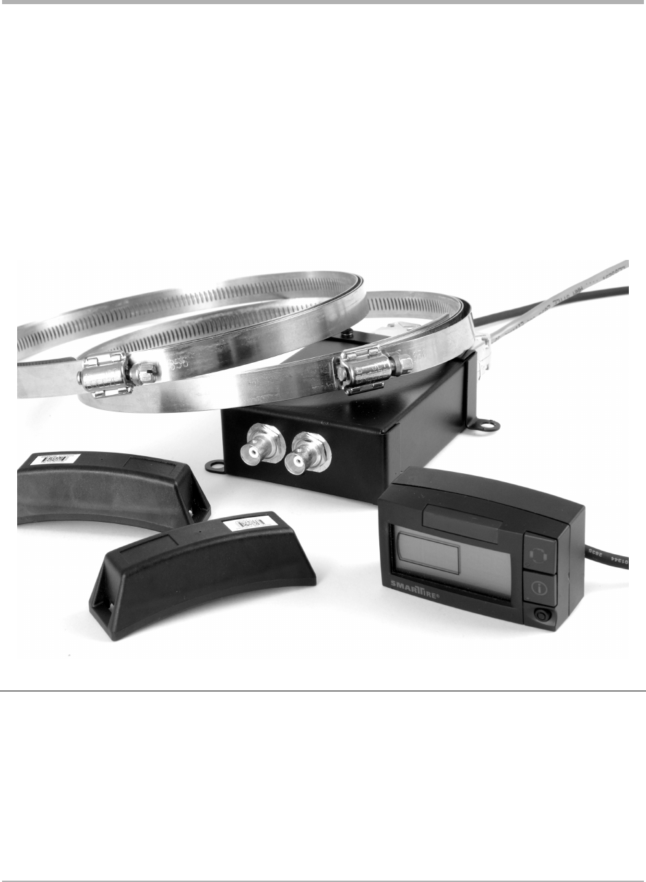
The SmarTire System consists of wheel mounted sensor/transmitters inside each tire which measure contained air
pressure and temperature and transmit this data to a Full Function Display within view of the driver.
Having carried out the correct installation procedure (see Installation section in this manual), the SmarTire system is
ready to use.

SmarTire Systems Inc.
Tire Monitor System Owner’s Manual Draft
2/25/2003 Page 5
This manual is under review by SmarTire
Operation
How It Works
The system operates continuously, transmitting air pressure and temperature data,
• At approximately 5 minute intervals when the vehicle is moving faster than 6 mph, unless pressure
changes, then data is transmitted within 7 seconds.
• Every 15 minutes when the vehicle is parked and pressure drops to 18 PSI or lower.

SmarTire Systems Inc.
Tire Monitor System Owner’s Manual Draft
2/25/2003 Page 6
This manual is under review by SmarTire
Installation
Transmitter Installation
Caution: Qualified personnel must perform the following installation procedures that highlight the steps required to
ensure that the transmitters are properly installed and undamaged. It does not include any standard procedures
normally required in the process of replacing a tire (i.e. lubrication, proper inflation and deflation procedures and
any other procedures deemed necessary by the tire manufacturer or dealer)
The equipment and images in this manual use one manufacturer’s tire changer and may not apply to you.
Tools Required
• Tire changing equipment
• Tire balancing equipment
• Hexagon socket and driver (5/16”)
• Metal cutter
• Torque wrench
SmarTire Systems Inc.
Tire Monitor System Owner’s Manual Draft
2/25/2003 Page 7
This manual is under review by SmarTire
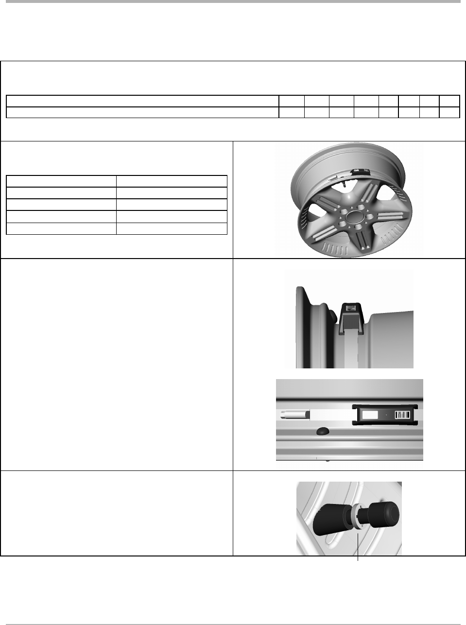
Installing Transmitter on a Wheel
Shorten the strap by cutting to the appropriate length for the wheel diameter used (see chart). Remove burrs from
strap end.
Wheel diameter 13 14 15 16 17
18 19
20
Cut-off length 21” 18” 15” 12” 9”
6” 3”
0”
Select a transmitter for a corresponding wheel location
(see chart). Pass strap through transmitter as shown.
Color Wheel Position
Green Right front
Red Left front
Blue Right rear
Yellow Left rear
The base of the drop centre well must be flat and wide
enough to allow the transmitter to contact the rim over
its complete width.
• Position the transmitter in the lowest area of the
drop centre well near the valve.
• Attach the strap end to the clamp by advancing
the wormgear with the socket driver. Tighten
to 30 inch pounds.
• Cut off excess strap length to approximately
one inch from the wormgear.
Attach the appropriate color of washer on the valve stem
as shown.
Proceed to mount the tire on the wheel.
SmarTire Systems Inc.
Tire Monitor System Owner’s Manual Draft
2/25/2003 Page 8
This manual is under review by SmarTire
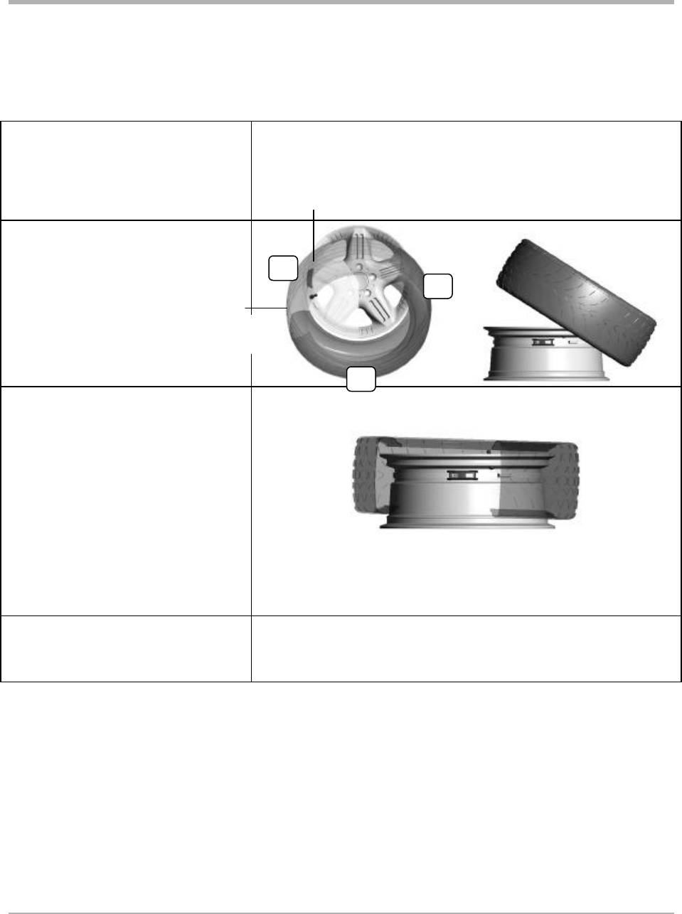
Mounting Tire with Transmitter on Wheel
To avoid damaging the transmitter
during tire mounting, position the wheel
with the transmitter located at 7 o’clock
in relation to the mount head at 12
o’clock.
Set the lubricated tire on the wheel with
its traction point 3 in. before the
transmitter. Use the mount head to guide
the rest of the bottom bead over the
flange and onto the rim.
With the bottom bead in place, you will
be able to position the wheel with the
transmitter at 7 o’clock for most tires.
Depress the bead into the drop centre so
that the traction point is 3 in. before the
transmitter.
Some stiff side wall tires (such as “run-
flats” require setting the transmitter
between 3 o’clock and 6 o’clock. Start
the top bead in front of the mount head
assisting with the mounting bar to
prevent slippage.
Inflate the tire to seat the bead, deflate
completely and then inflate the tire to
manufacturer’s recommended cold
inflation pressure.
12
7
Transmitter
Traction
point
3