Berthold Technologies FCC01X01 Moisture Measuring System User Manual
Berthold Technologies Moisture Measuring System
UserManual.wiki
>
Berthold Technologies
>
FCC01X01 User Manual
User Manual
Navigation menu
Upload a User Manual
Namespaces
Wiki Guide
HTML
PDF
Info
Views
User Manual
Discussion / Help
Navigation
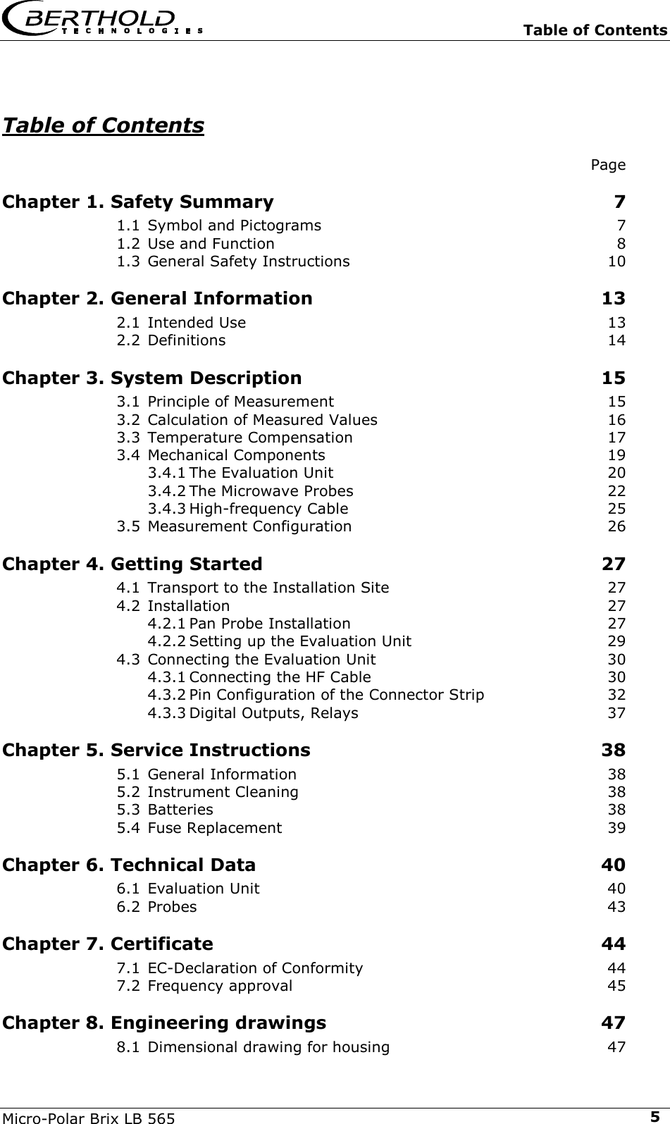

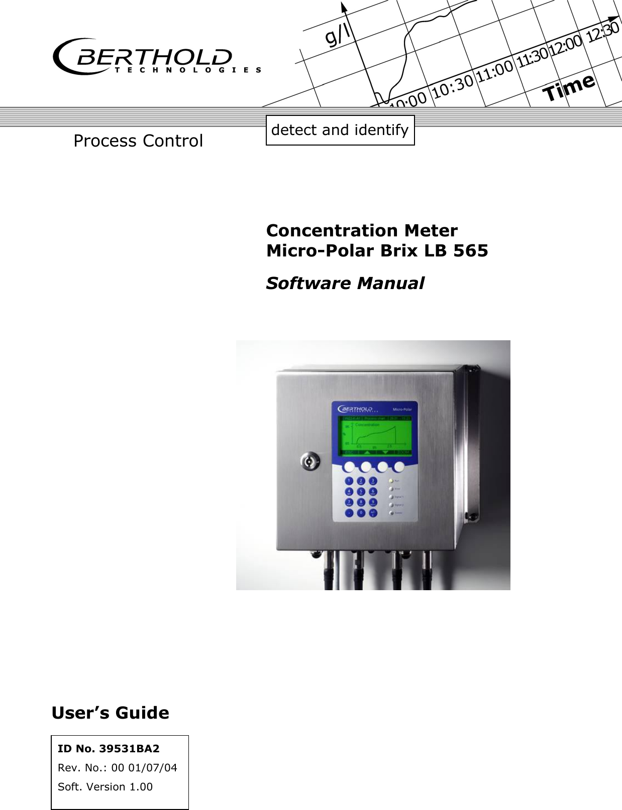
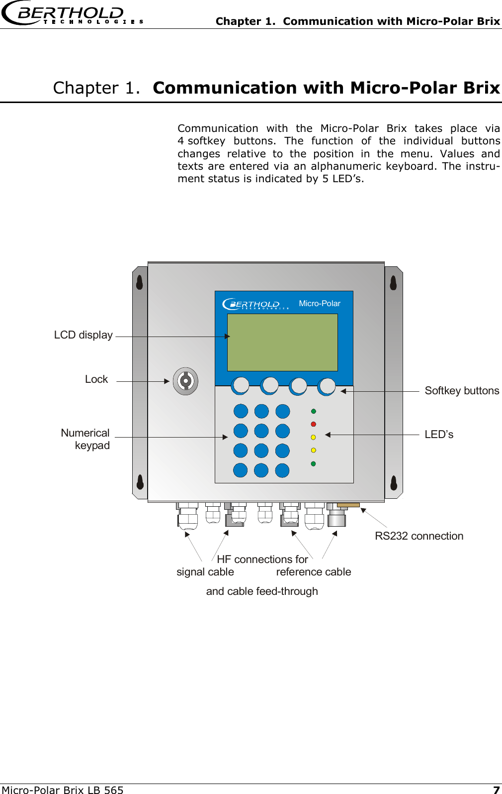
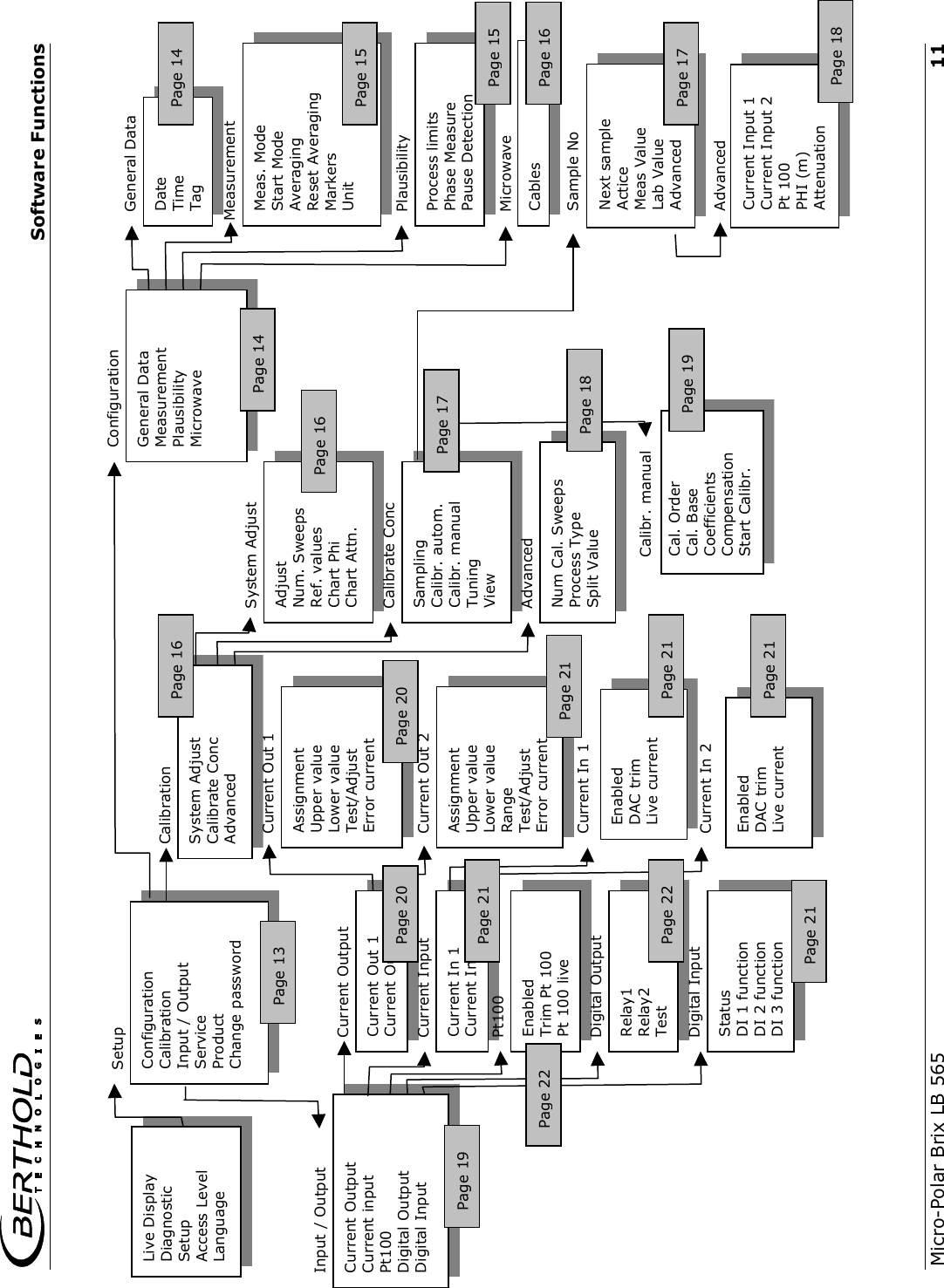
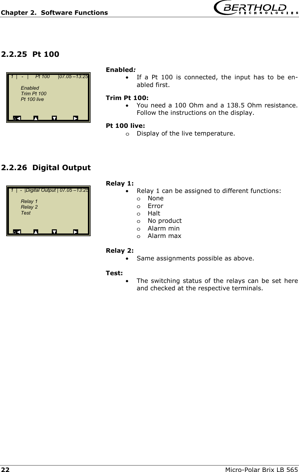
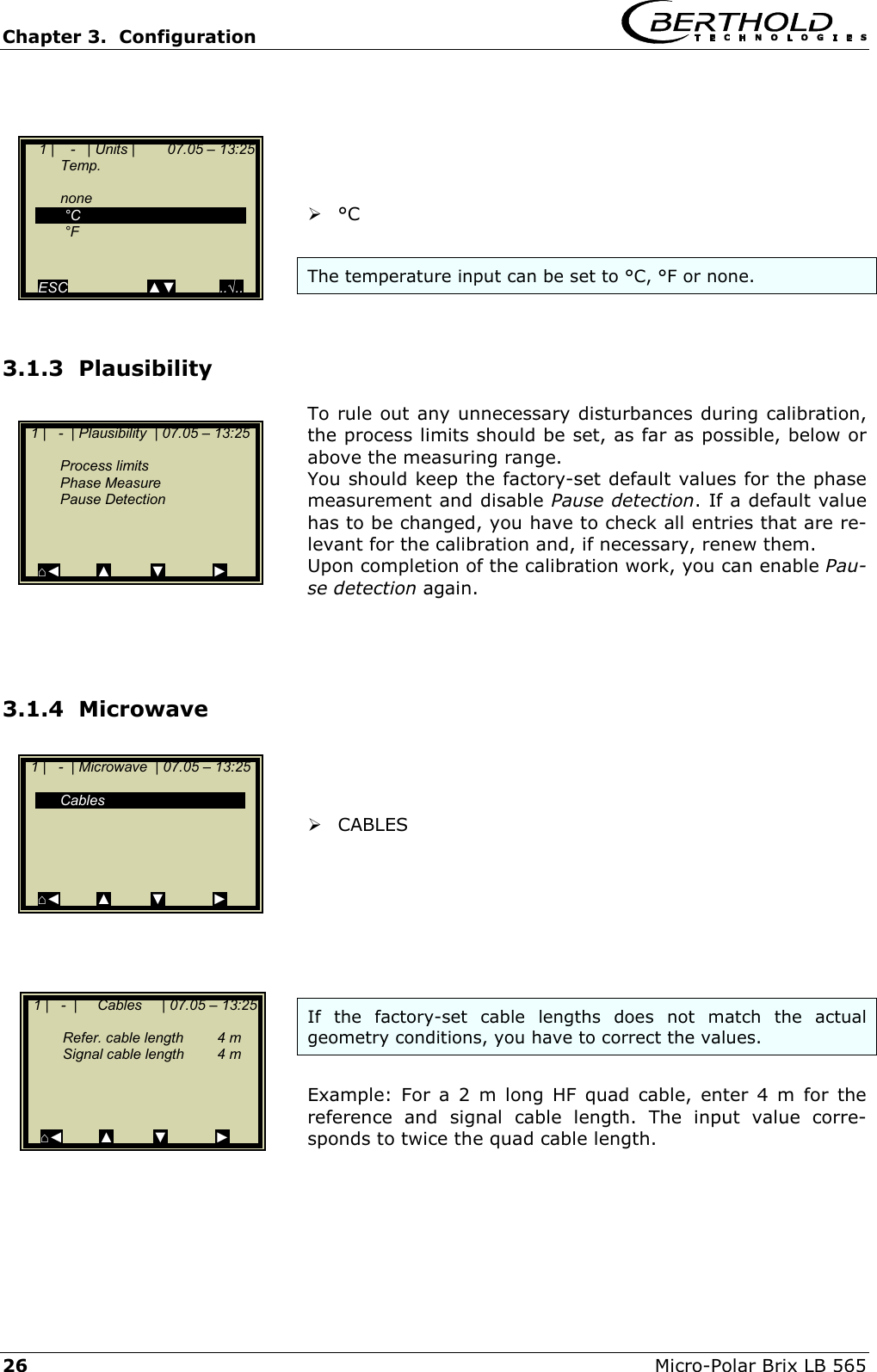
![Chapter 3 System Description Micro-Polar Brix LB 565 173.3 Temperature Compensation Temperature compensation (TC) has to be carried out if varying op-erating states are likely to occur, for example vapour pressure and product temperature. TC has to be carried out whenever you are working with cooling crystallizers. The following formulas are used for temperature compensation. Linear compensation Additive: θ∆⋅+ϕ=ϕ ϕTCmeascomp θ∆⋅+= Dmeascomp TCDD Multiplicative: )TC(meascomp θ∆⋅+ϕ=ϕ ϕ1 )TC(DD Dmeascomp θ∆⋅+= 1 Quadratic compensation Additive: ()θ∆⋅θ∆⋅+θ∆⋅+ϕ=ϕ ϕϕ argTCTCmeascomp221 ()θ∆⋅θ∆⋅+θ∆⋅+= argTCTCDD DDmeascomp221 Multiplicative: ())argTCTC(meascomp θ∆⋅θ∆⋅+θ∆⋅+ϕ=ϕ ϕϕ2211 ())argTCTC(DD DDmeascomp θ∆⋅θ∆⋅+θ∆⋅+= 2211 Where ϕmeas = measured phase [°] ϕcomp = compensated phase [°] Dmeas = measured attenuation [dB] Dmeas = compensated attenuation [dB] TCϕx = temperature coefficient [° / °C] TCDx = temperature coefficient [dB/ °C] ∆θ = measured temperature (Tmeas ) – reference temp. (TRef) θ∆ = difference temperature ()θ∆arg = algebraic sign of difference temperature Depending on the selected function (additive, multiplicative, quad-ratic, cubic), the required temperature coefficients appear on the Calibration menu. Temperature coefficients that are not used are set to zero.](https://usermanual.wiki/Berthold-Technologies/FCC01X01/User-Guide-585001-Page-17.png)


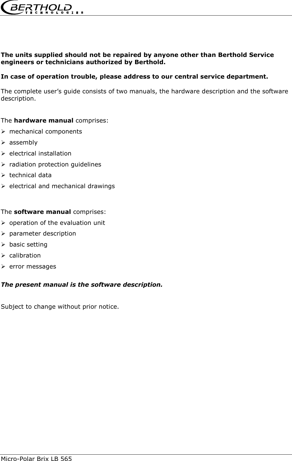

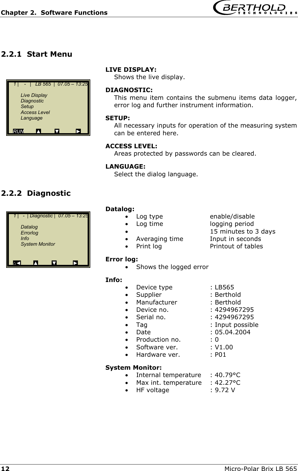
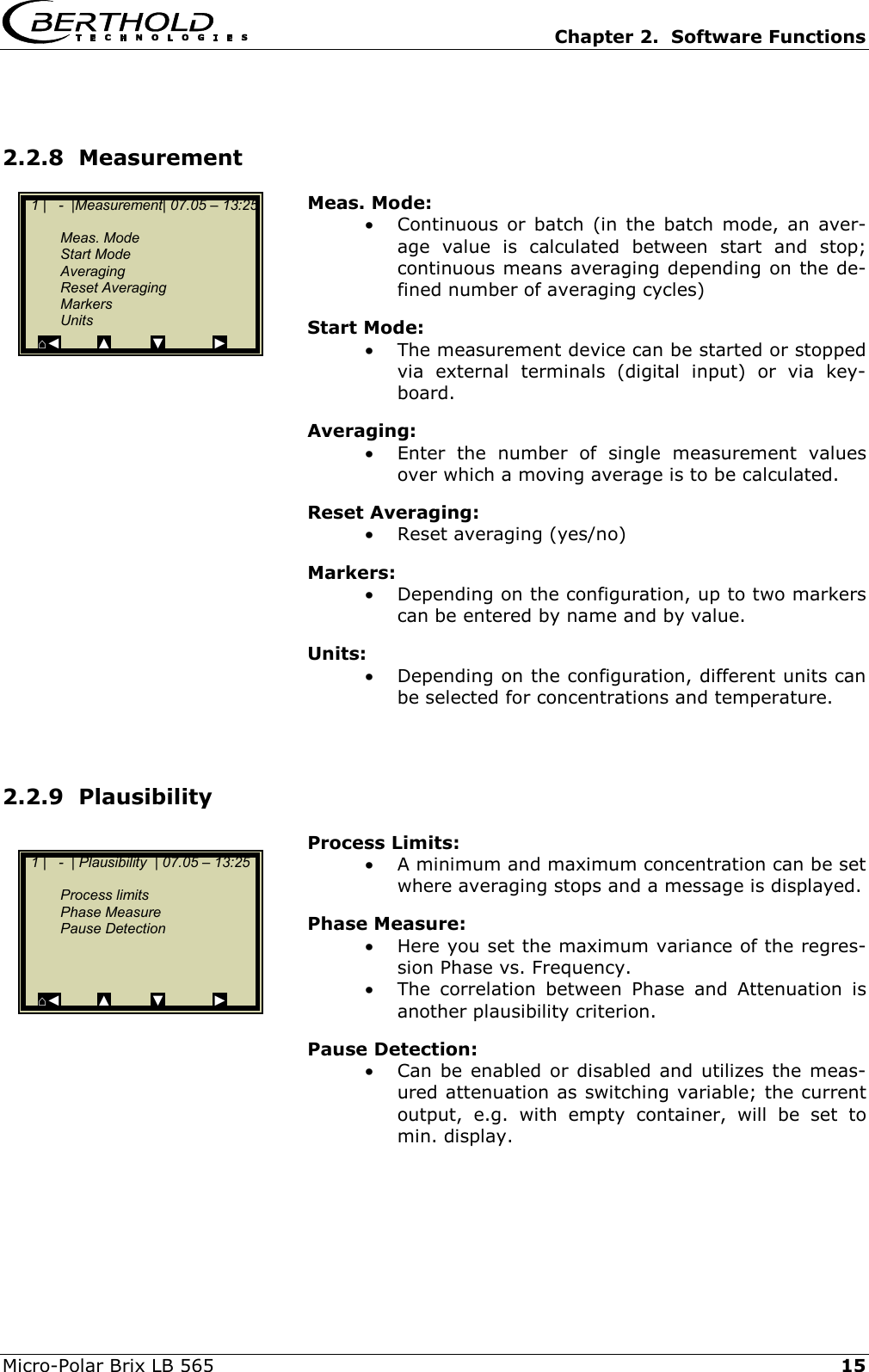
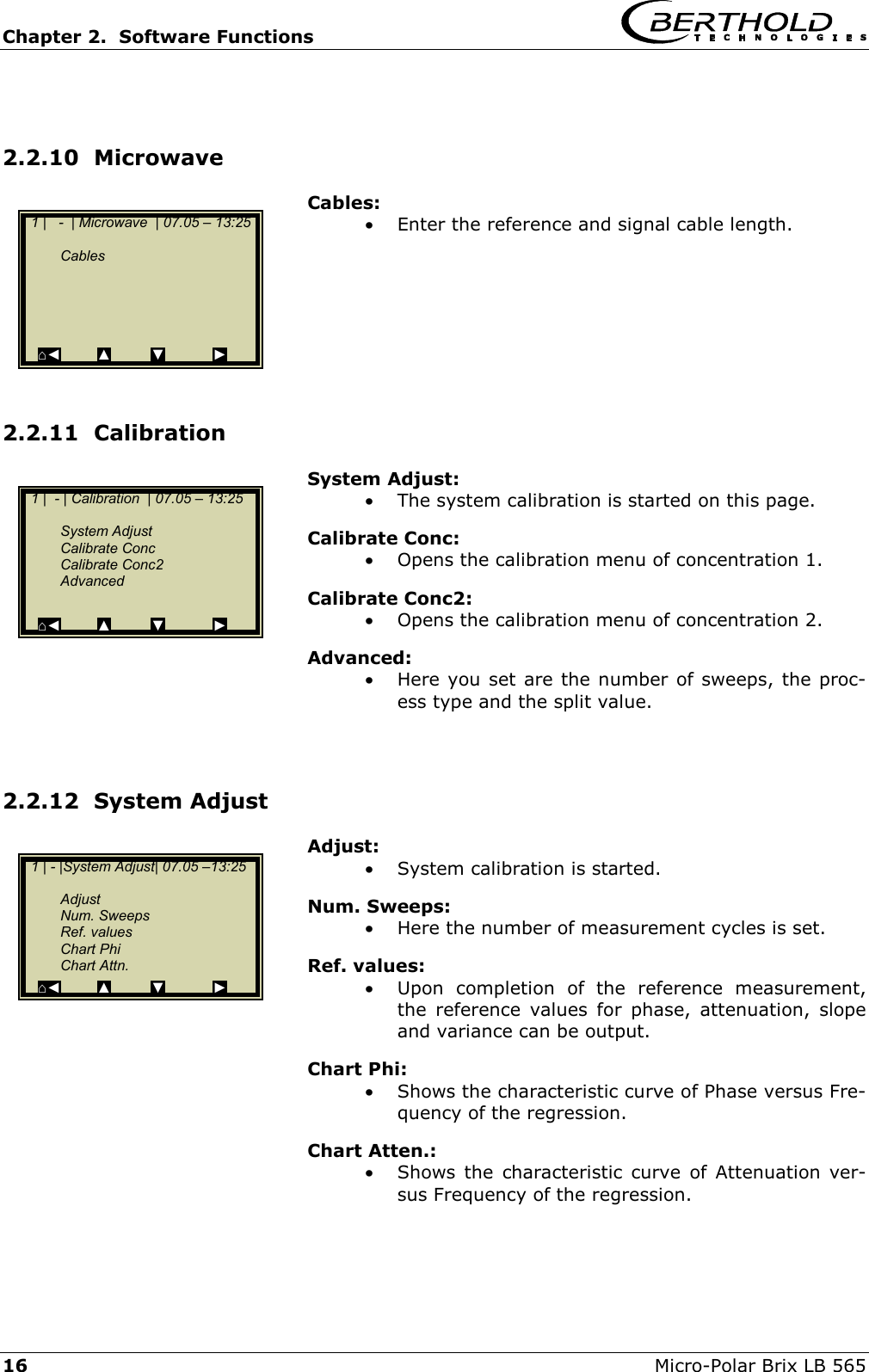
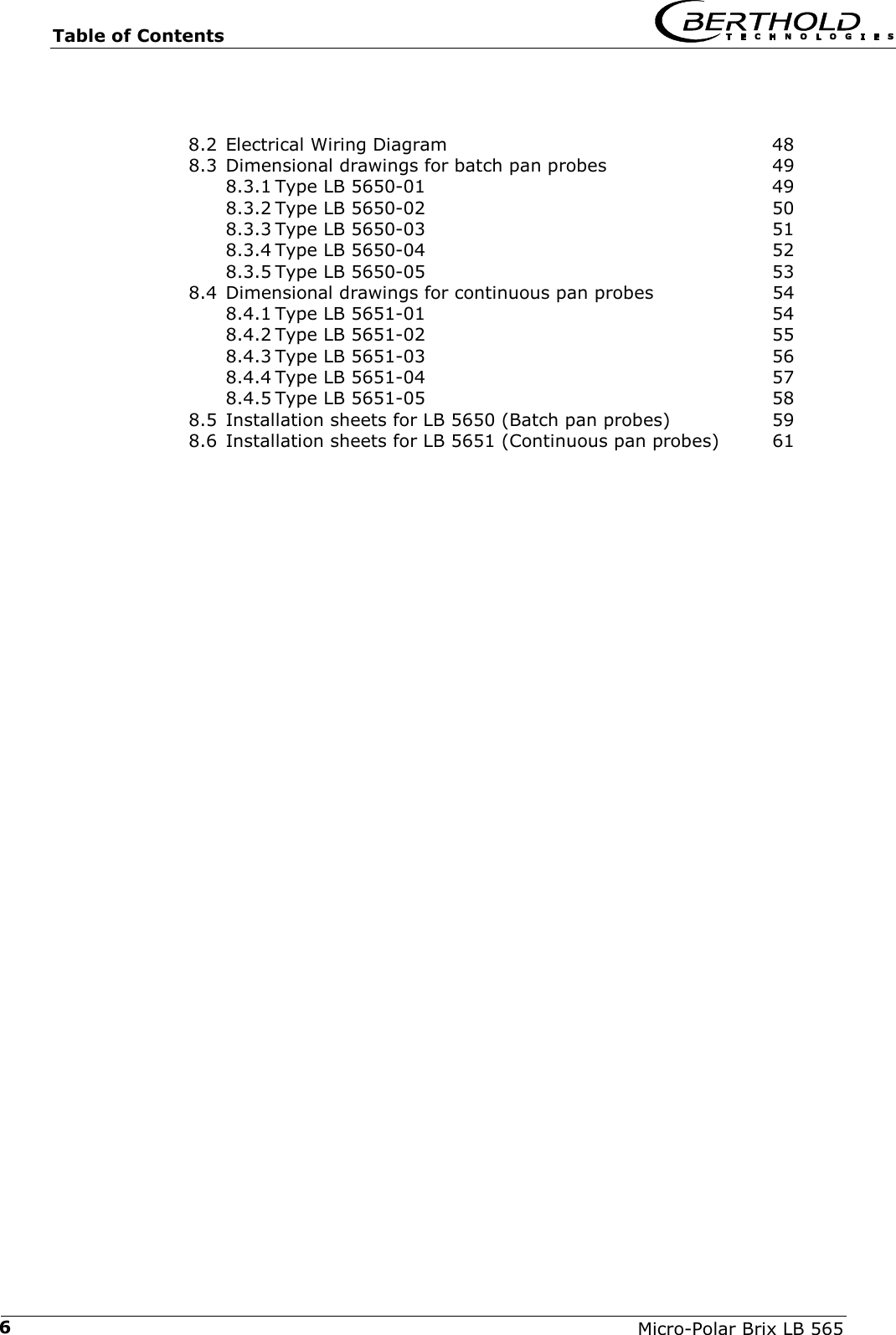
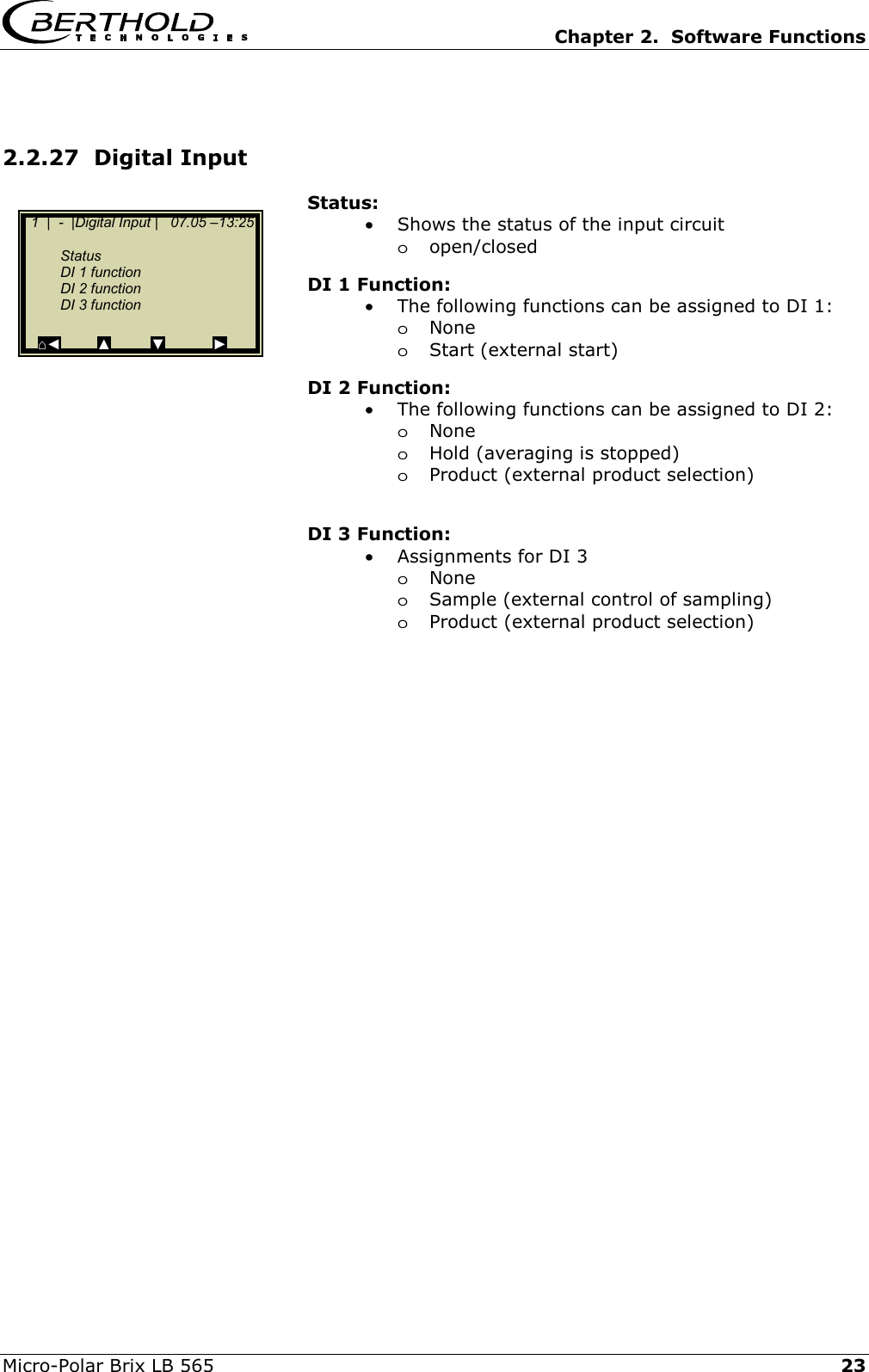
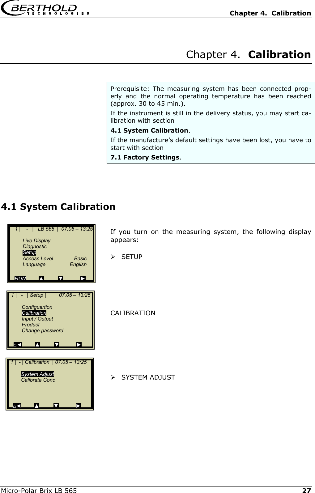
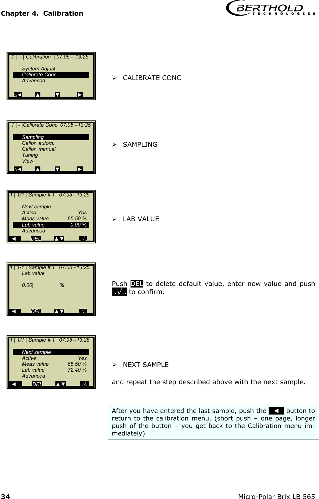
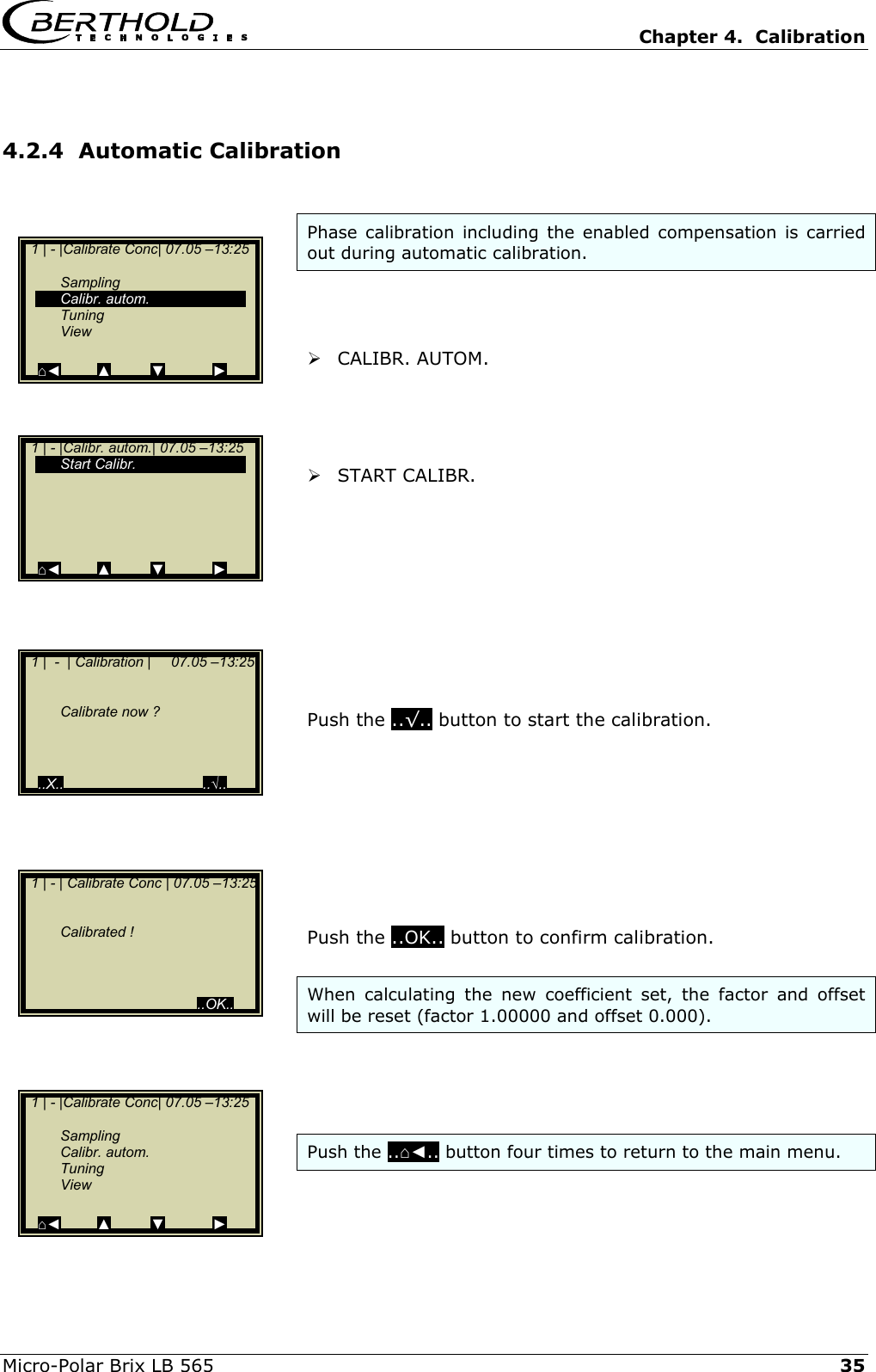
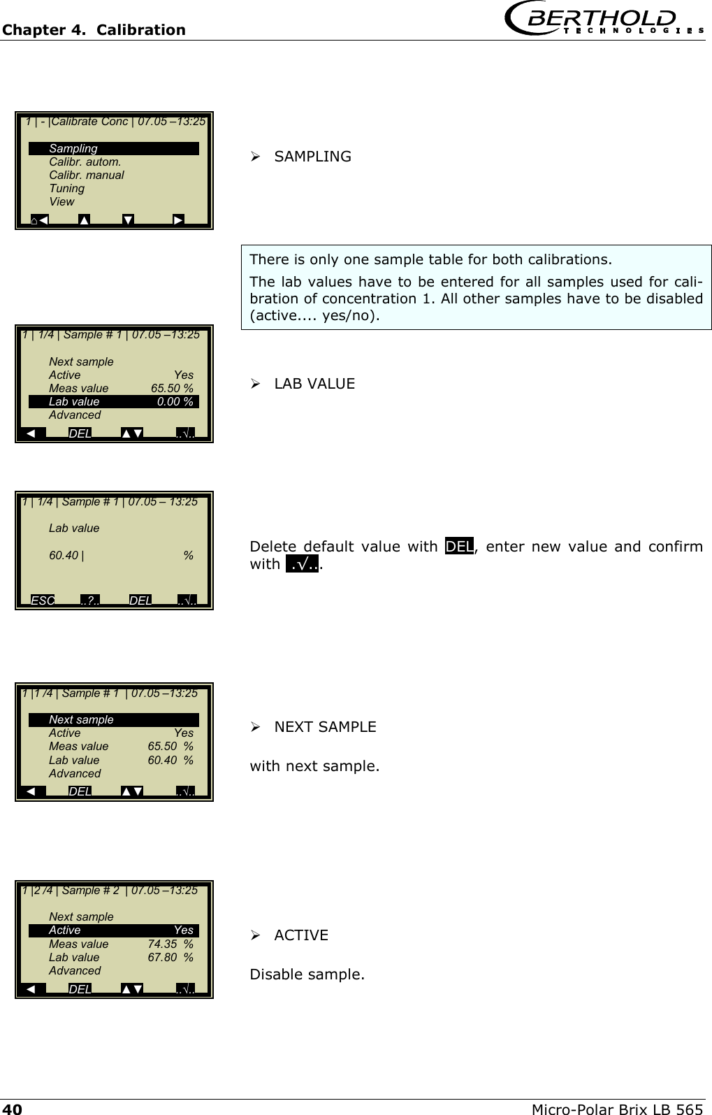
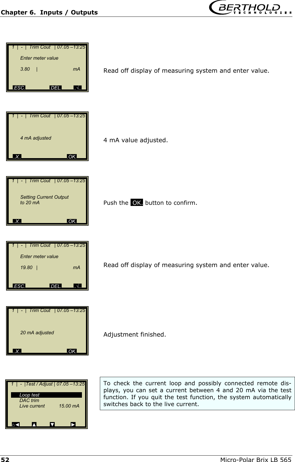
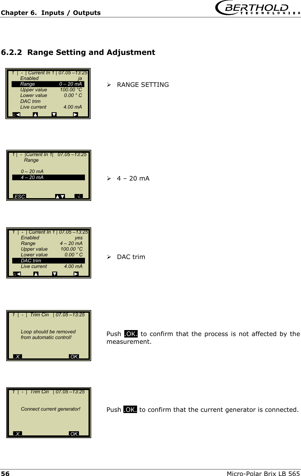
![Chapter 2. Software Functions Micro-Polar Brix LB 565 17 2.2.13 Calibrate Concentration Sampling: • Shows all measured samples. Calibr. autom.: • Calibration can be started after measurement of two samples and input of the respective laboratory values. Calibr. manual: • Here you can choose the calibration order [lin-ear/quadratic], the basis [phase/attenuation or both] and compensation [temperature]. Tuning: • Subsequent correction of the reading is possible by entering a factor and an offset. View: • Presentation of calibration curve, display of correla-tion and coefficients. 2.2.14 Sample No. Sample number, date and time of the sample measurement are displayed in the header. Next sample: • Continues with the next sample. Active: • Here you can choose if this sample should be taken into account in the calibration. Measured value: • Display of the measured values, calculated with the actual coefficient. Lab value: • Entry position for the laboratory value. Advanced: • Switches to the next data page. 1 | - |Calibrate Conc| 07.05 –13:25 Sampling Calibr. autom. Calibr. manual Tuning View ⌂◄ ▲ ▼ ► 1 | 1/1 | Sample # 1 | 07.05 –13:25 Next sample Active Yes Meas value 65.50 % Lab value 0.00 % Advanced ◄ DEL ▲▼ ..√..](https://usermanual.wiki/Berthold-Technologies/FCC01X01/User-Guide-585001-Page-83.png)
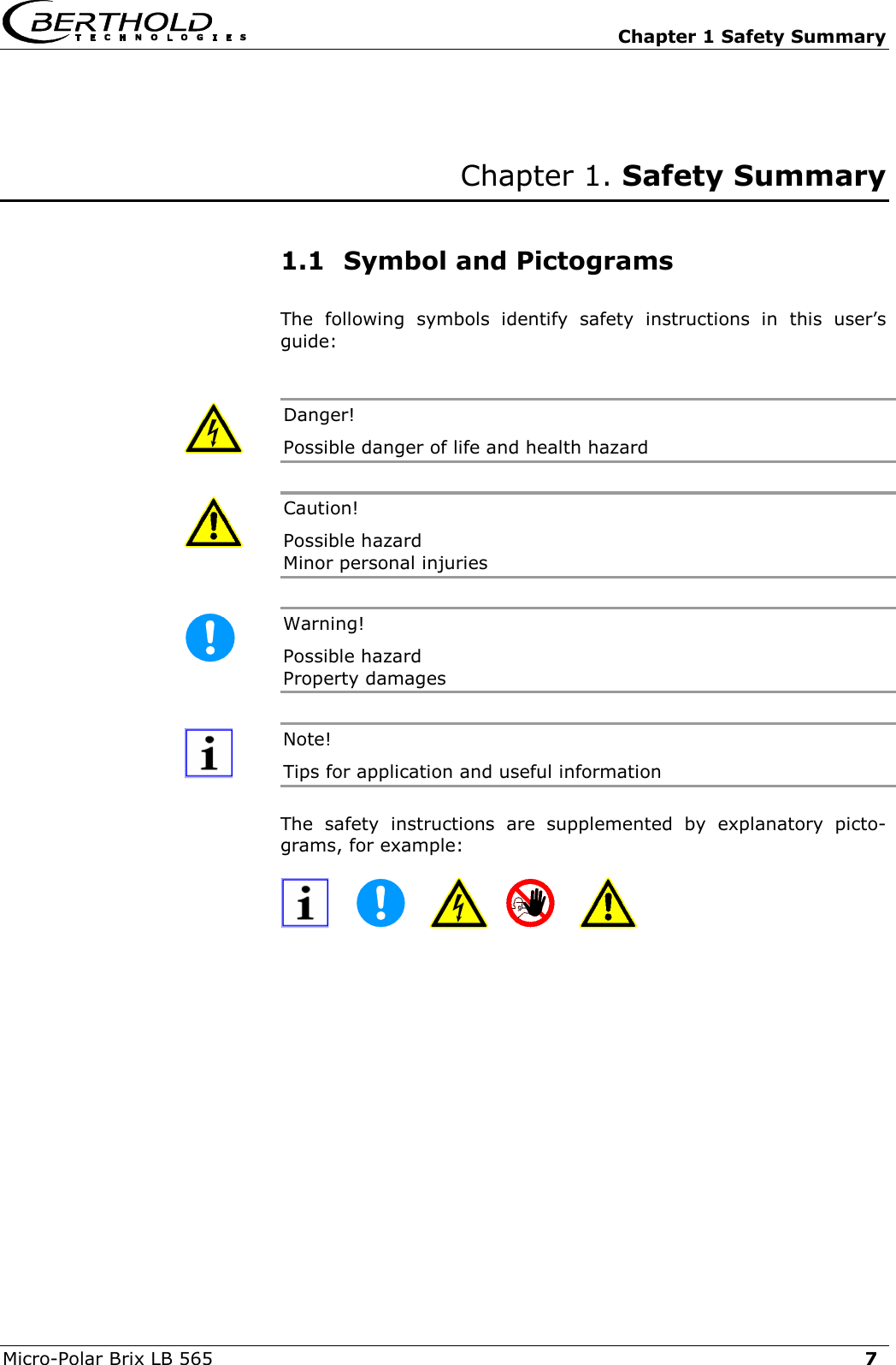
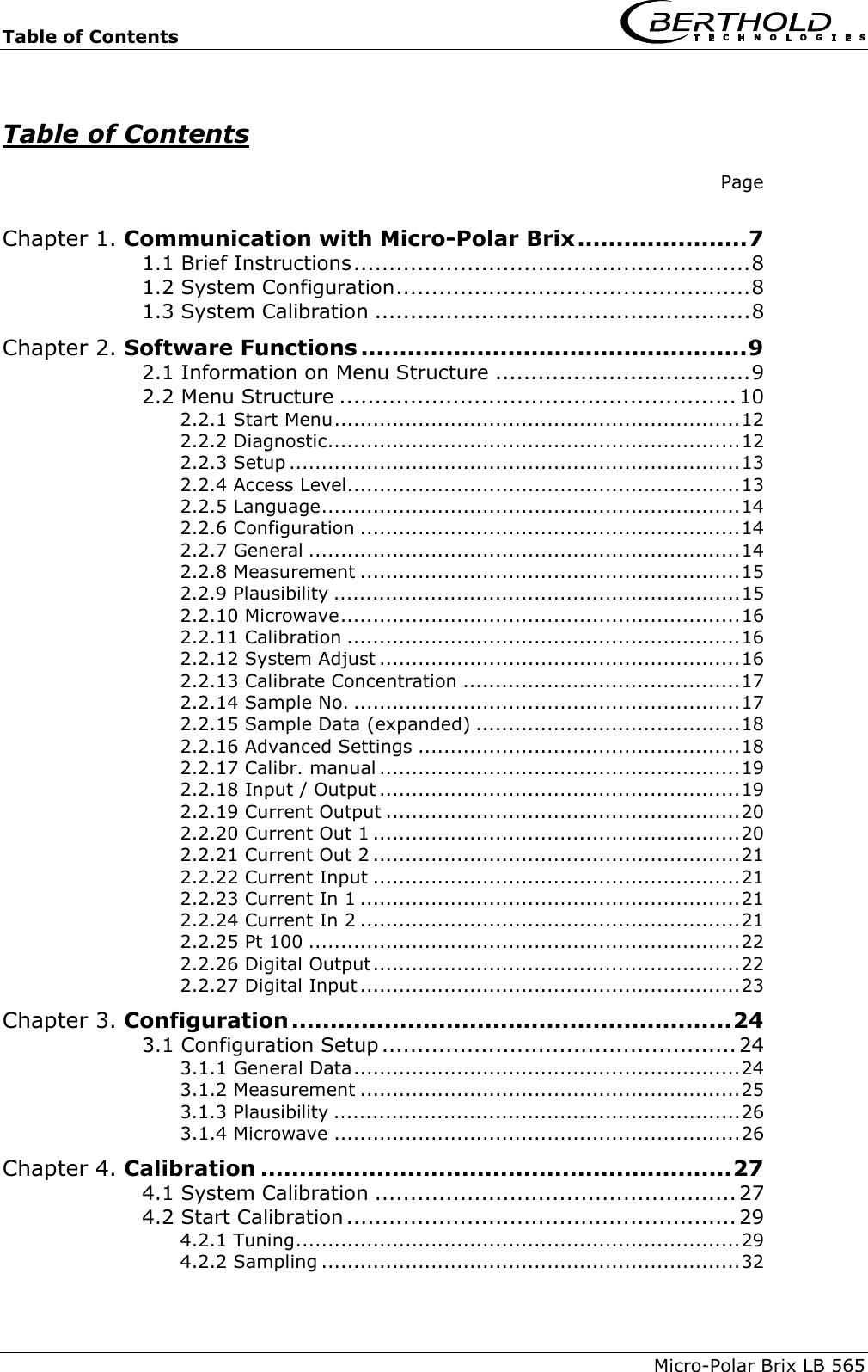
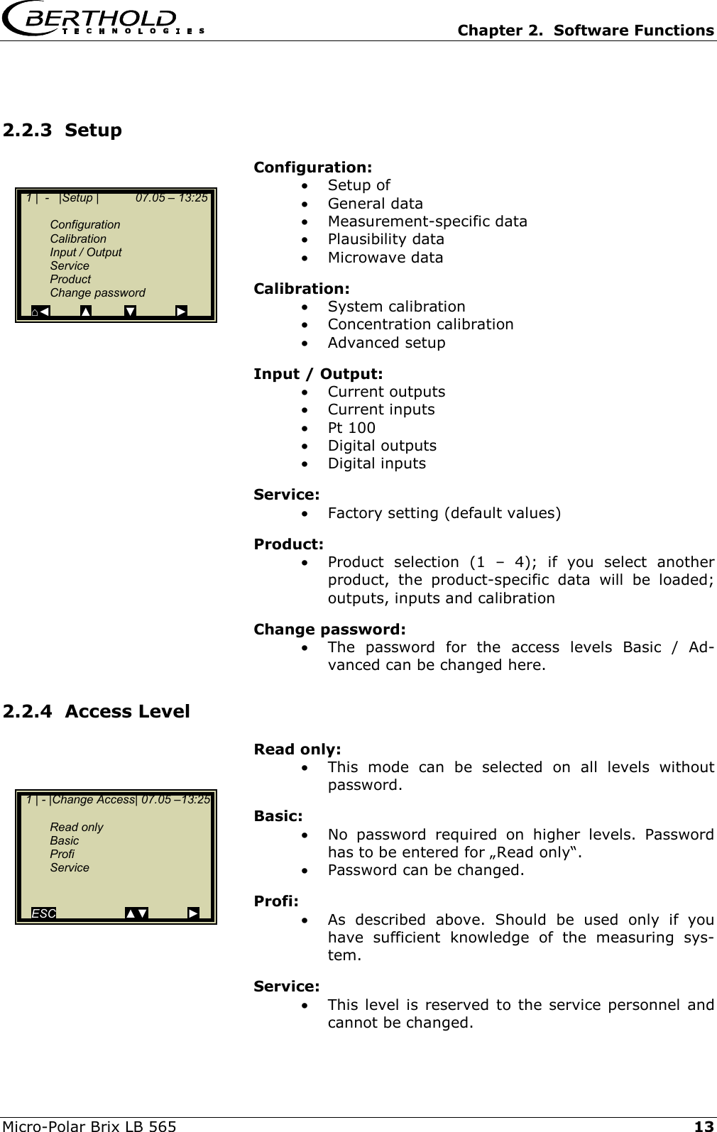
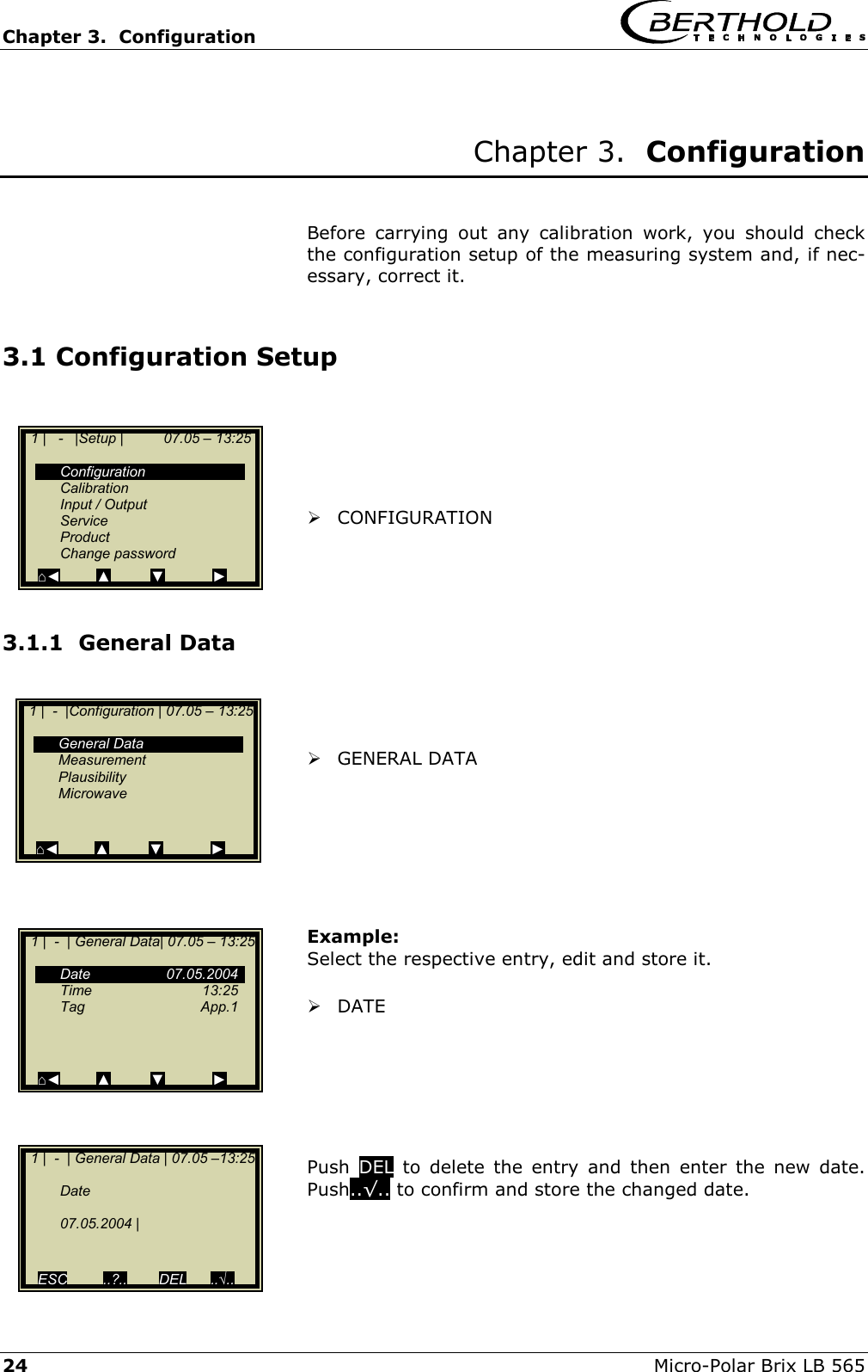
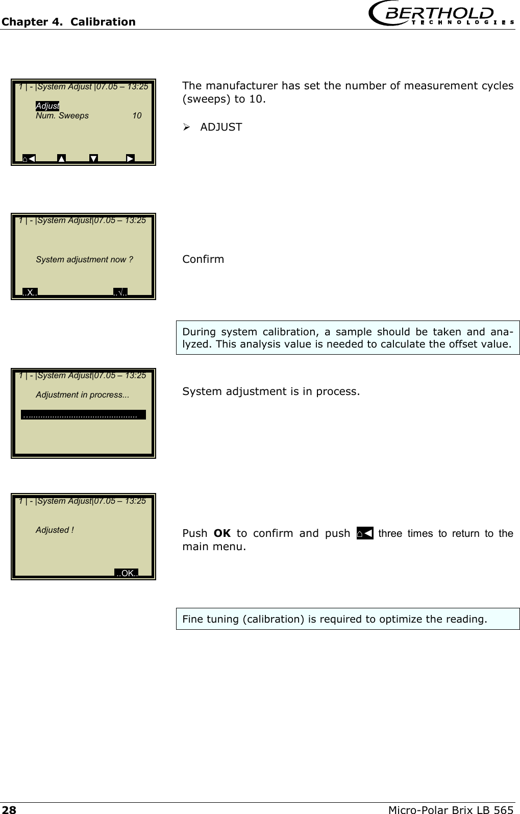
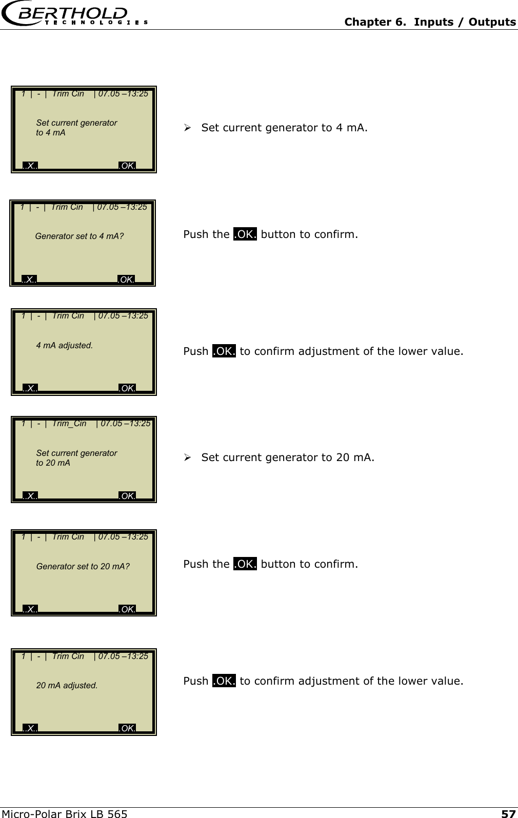
![Chapter 2. Software Functions 18 Micro-Polar Brix LB 565 2.2.15 Sample Data (expanded) Current In 1: • Editable display of the first compensation input. Current In 2: • Editable display of the second compensation input. Pt 100: • Editable display of the Pt 100 input. PHI (m): • Not editable display of the measured phase. Atten: • Not editable display of the measured attenuation. 2.2.16 Advanced Settings Number of Calibration Sweeps: • Freely selectable number of individual measure-ments [Sweeps] used for determination of a cali-bration point. Process Type: • Select the operation mode: oone concentration [1 measuring range] otwo concentrations [2 measuring ranges] osplit concentration [1 measuring range with switching point (split value) for coefficient switchover]. Split Value: • Setting of the switching point on a value basis. 1| - |Advanced | 07.05 –13:25 Num Cal. Sweeps Process Type Split Value ⌂◄ ▲ ▼ ► 1 | 1/1 | Sample # 1 | 07.05 –13:25 Current In 1 Current In 2 Pt 100 PHI (m) Atten ◄ DEL ▲▼ ..√..](https://usermanual.wiki/Berthold-Technologies/FCC01X01/User-Guide-585001-Page-84.png)
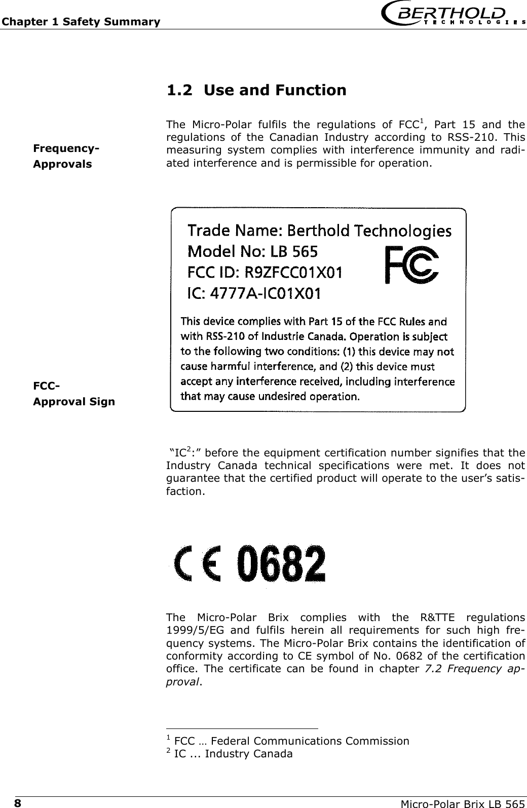
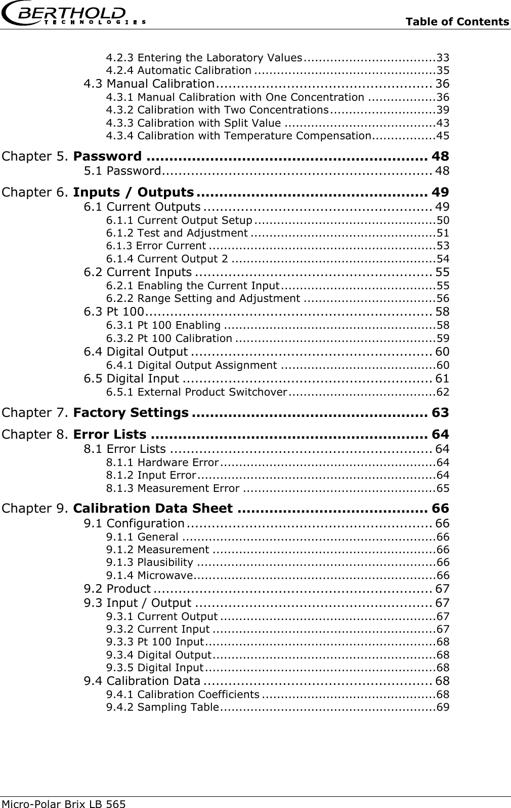
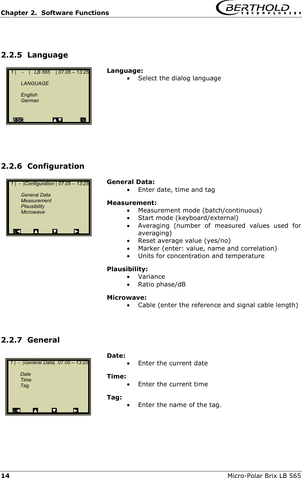
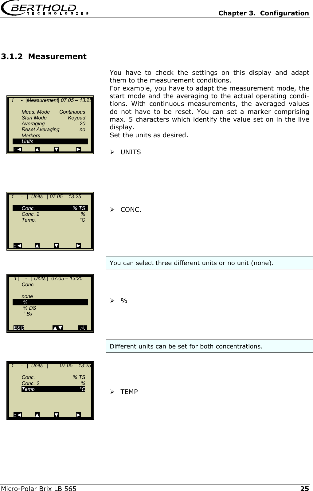
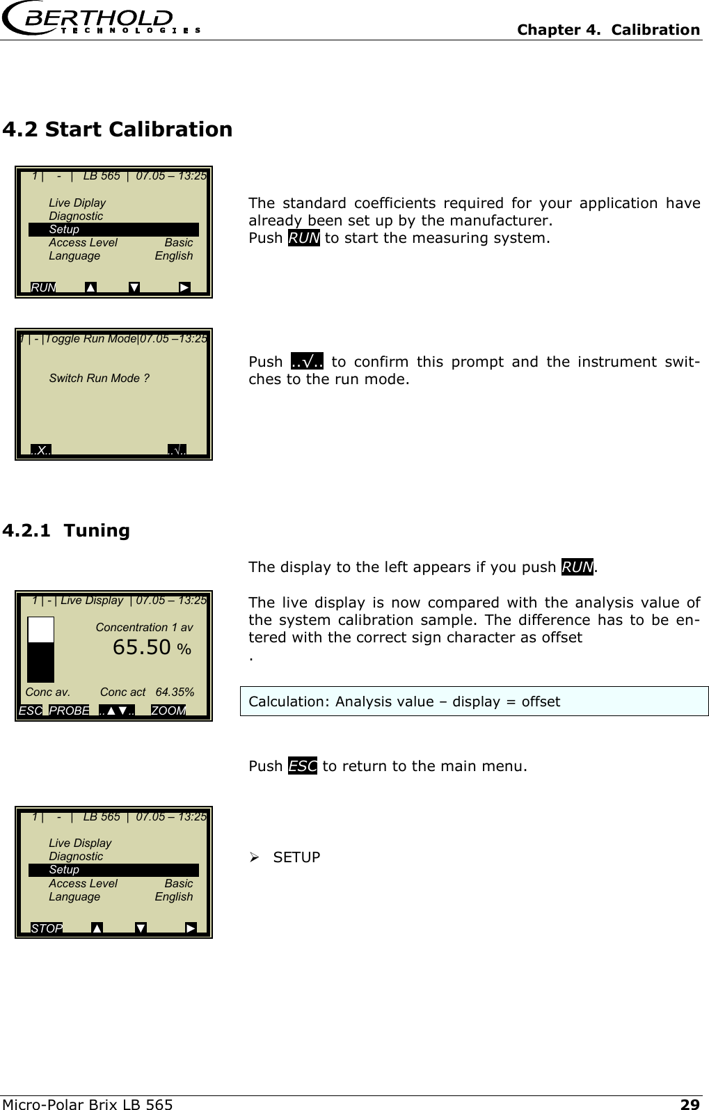
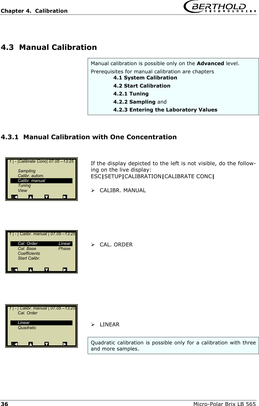
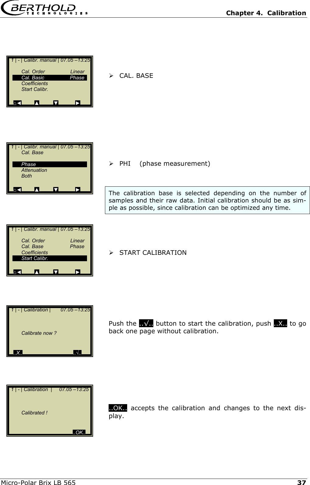
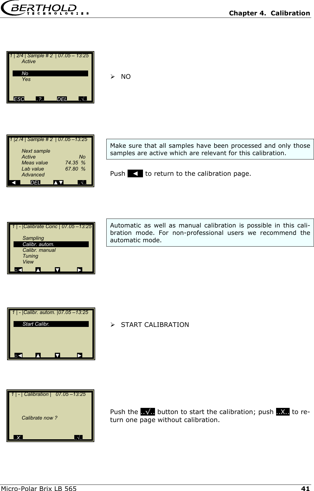
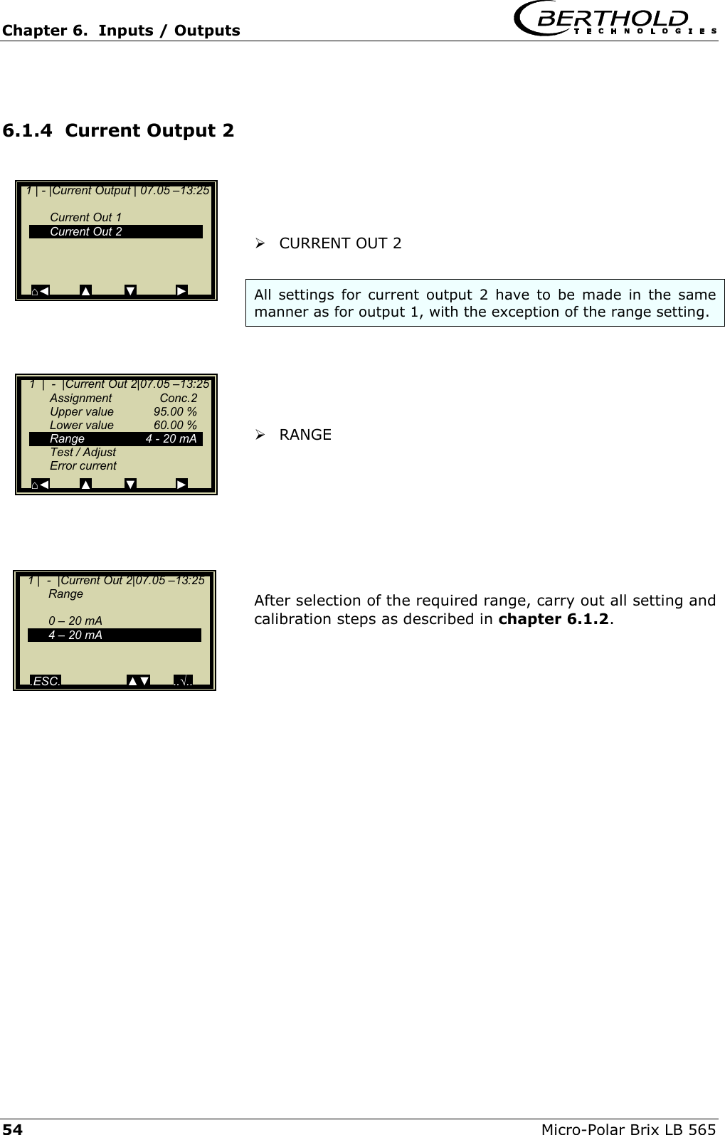
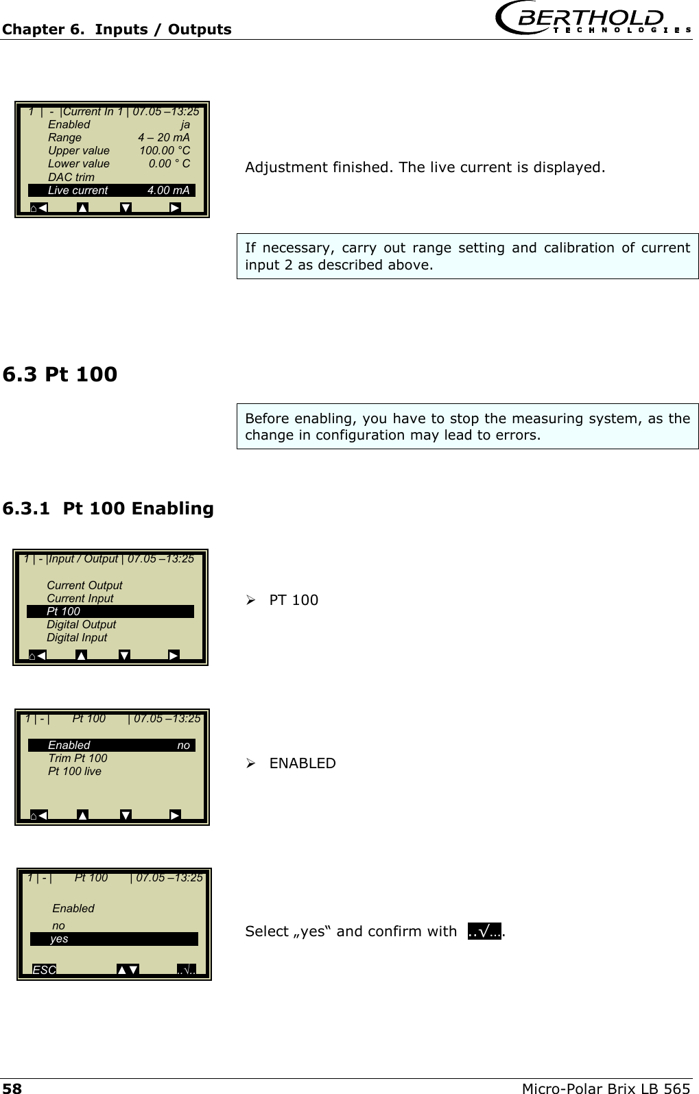
![Chapter 2. Software Functions Micro-Polar Brix LB 565 19 2.2.17 Calibr. manual Cal. Order: • Here you define the calibration order [lin-ear/quadratic] Cal. Base: • The following parameters can be set: oPhase oAttenuation oPhase and attenuation Coefficients: • Here you can edit all coefficients for phase and at-tenuation. Start Calibr.: • Starts the calibration using the parameters you have set earlier. 2.2.18 Input / Output Current Output: • Both outputs can be adjusted, assigned and set up on the selected level. Current Input: • Activation level of current input, calibration and display of the live current signal. Pt 100: • Here you can enable and adjust a connected Pt 100. Display of the actual temperature signal. Digital Output: • Allocation of relays 1 and 2 and test function. Digital Input: • Status control and assignment of the digital inputs. 1 | - | Calibr. manual | 07.05 –13:25 Cal. Order Cal. Base Coefficients Start Calibr. ⌂◄ ▲ ▼ ► 1 | - |Input / Output | 07.05 –13:25 Current Output Current Input Pt 100 Digital Output Digital Input ⌂◄ ▲ ▼ ►](https://usermanual.wiki/Berthold-Technologies/FCC01X01/User-Guide-585001-Page-85.png)
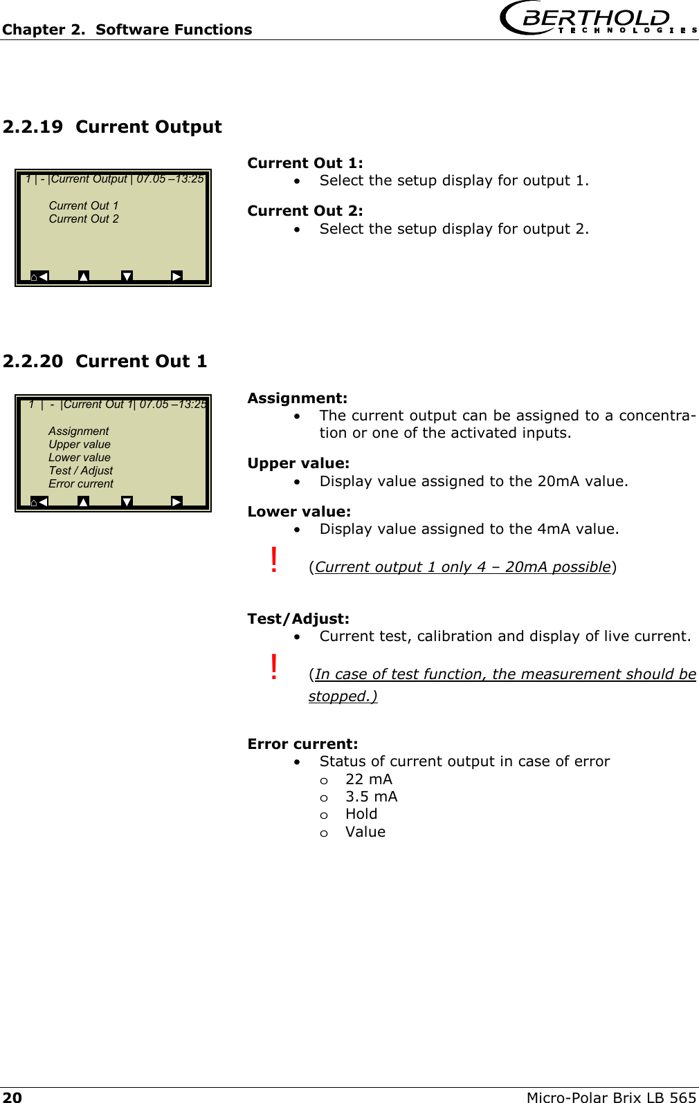
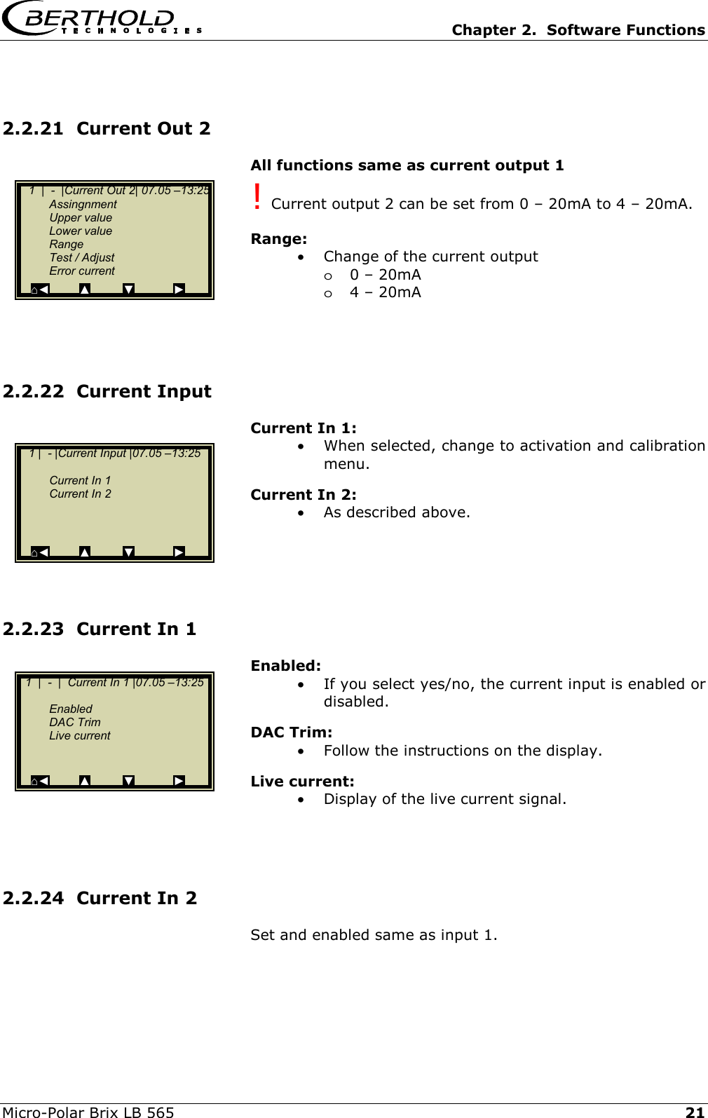
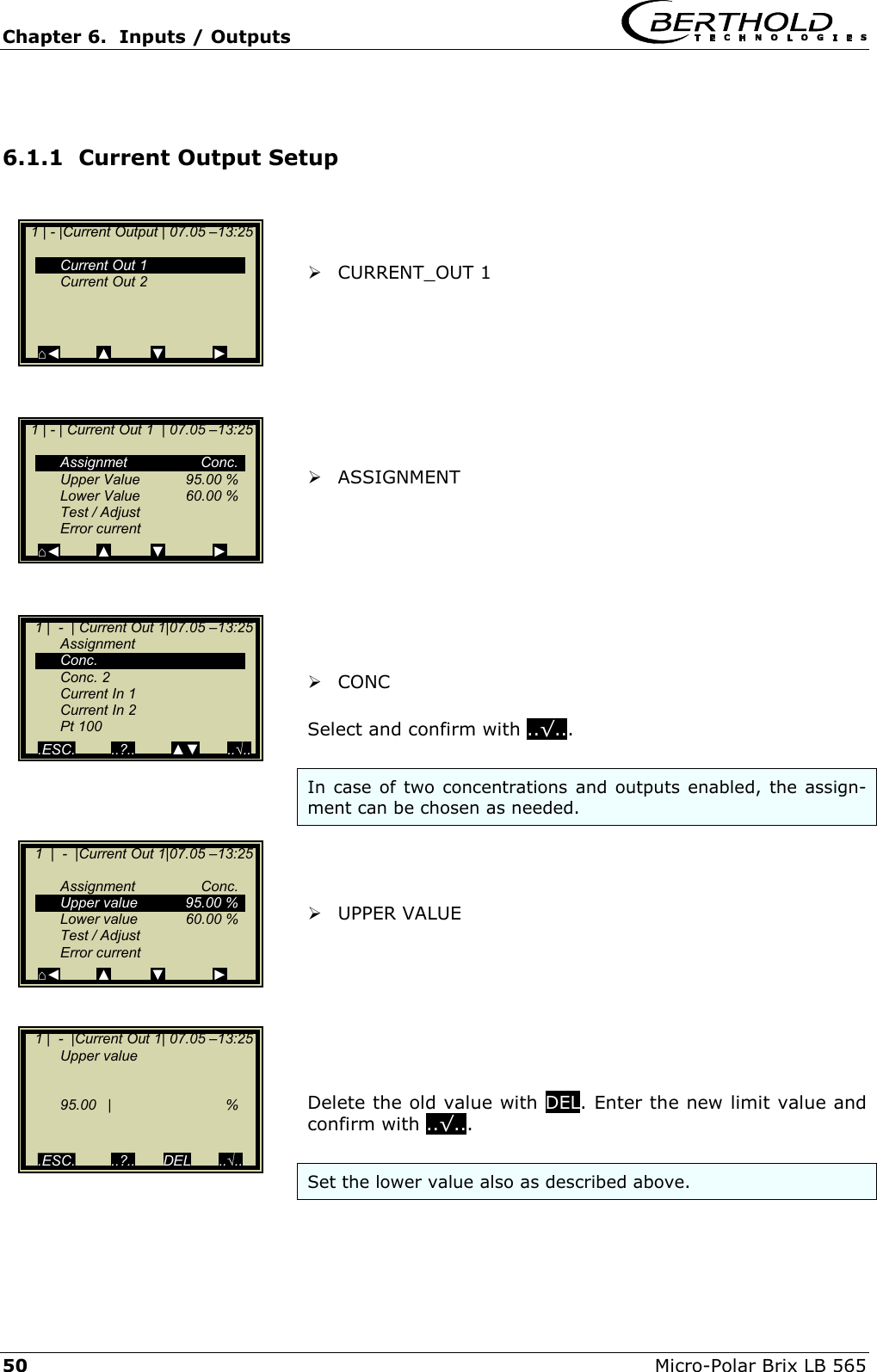
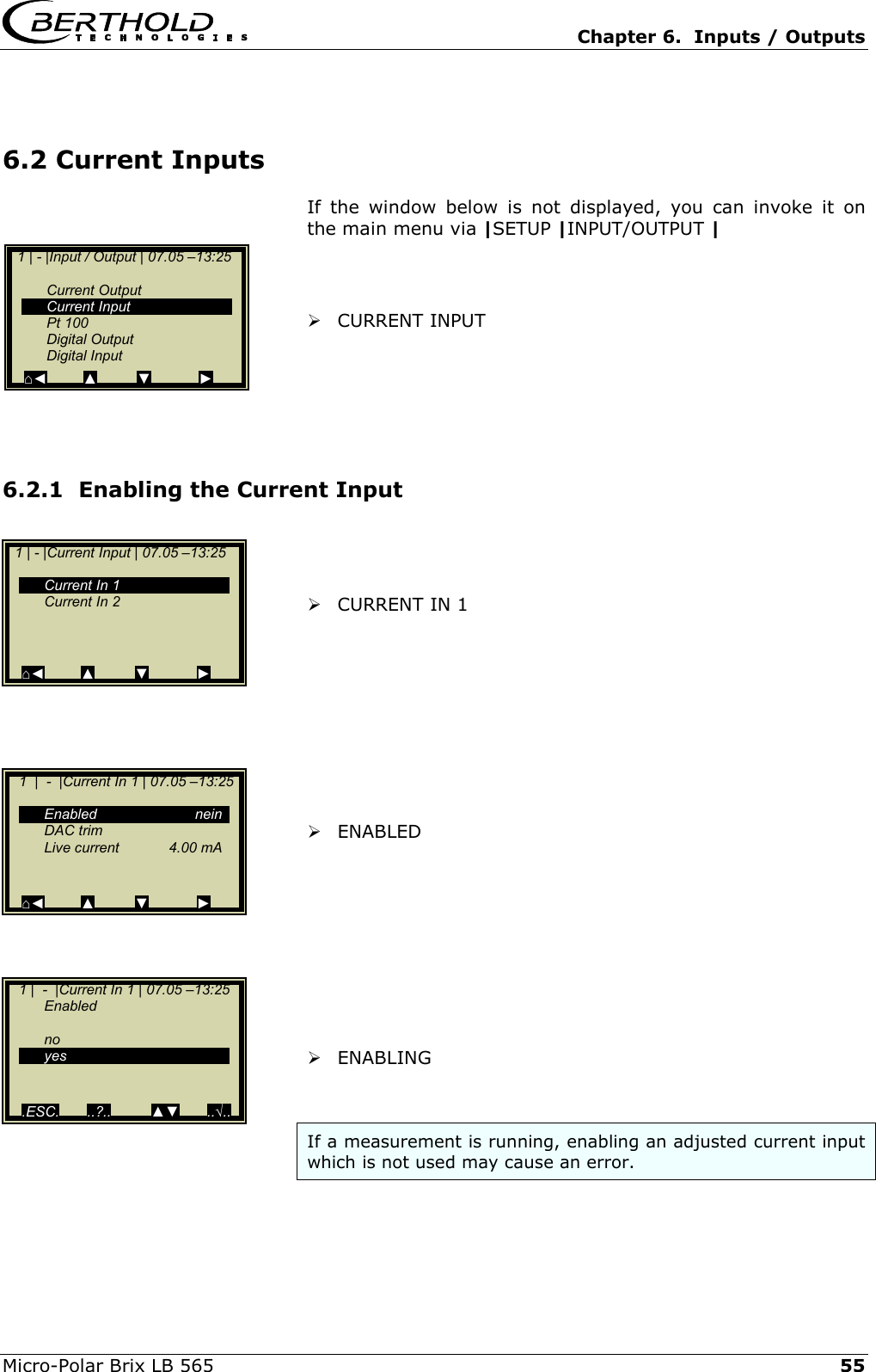
![Chapter 6. Inputs / Outputs Micro-Polar Brix LB 565 53 6.1.3 Error Current Different signal effects can be assigned to the output current. ERROR CURRENT ALARM MODE Fixed values, Hold or freely adjustable values between 0 and 24 mA can be assigned. VALUE With this setting, you can default any current value for the error case. ! CAUTION: The current output 1 can only be set between 3.5 mA and 24 mA. [HART®] Enter value and confirm with ..√... 1 | - |Current Out 1|07.05 –13:25 Assignment Conc. Upper value 95.00 % Lower value 60.00 % Test / Adjust Error current ⌂◄ ▲ ▼ ► 1 | - | Error current | 07.05 –13:25 Alarm Mode Value 22.00 mA ⌂◄ ▲ ▼ ► 1 | - | Error current |07.05 –13:25 Alarm mode 22.00 mA 3.5 mA Hold Value ⌂◄ ▲ ▼ ► 1 | - |Error current| 07.05 –13:25 Value 3.50 mA ESC DEL ..√..](https://usermanual.wiki/Berthold-Technologies/FCC01X01/User-Guide-585001-Page-119.png)
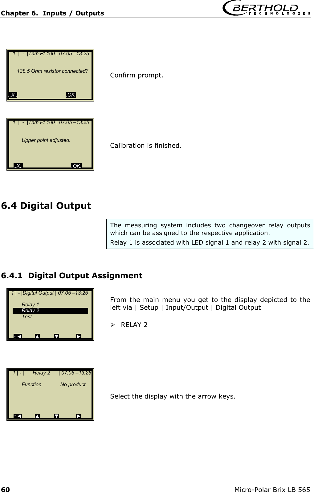
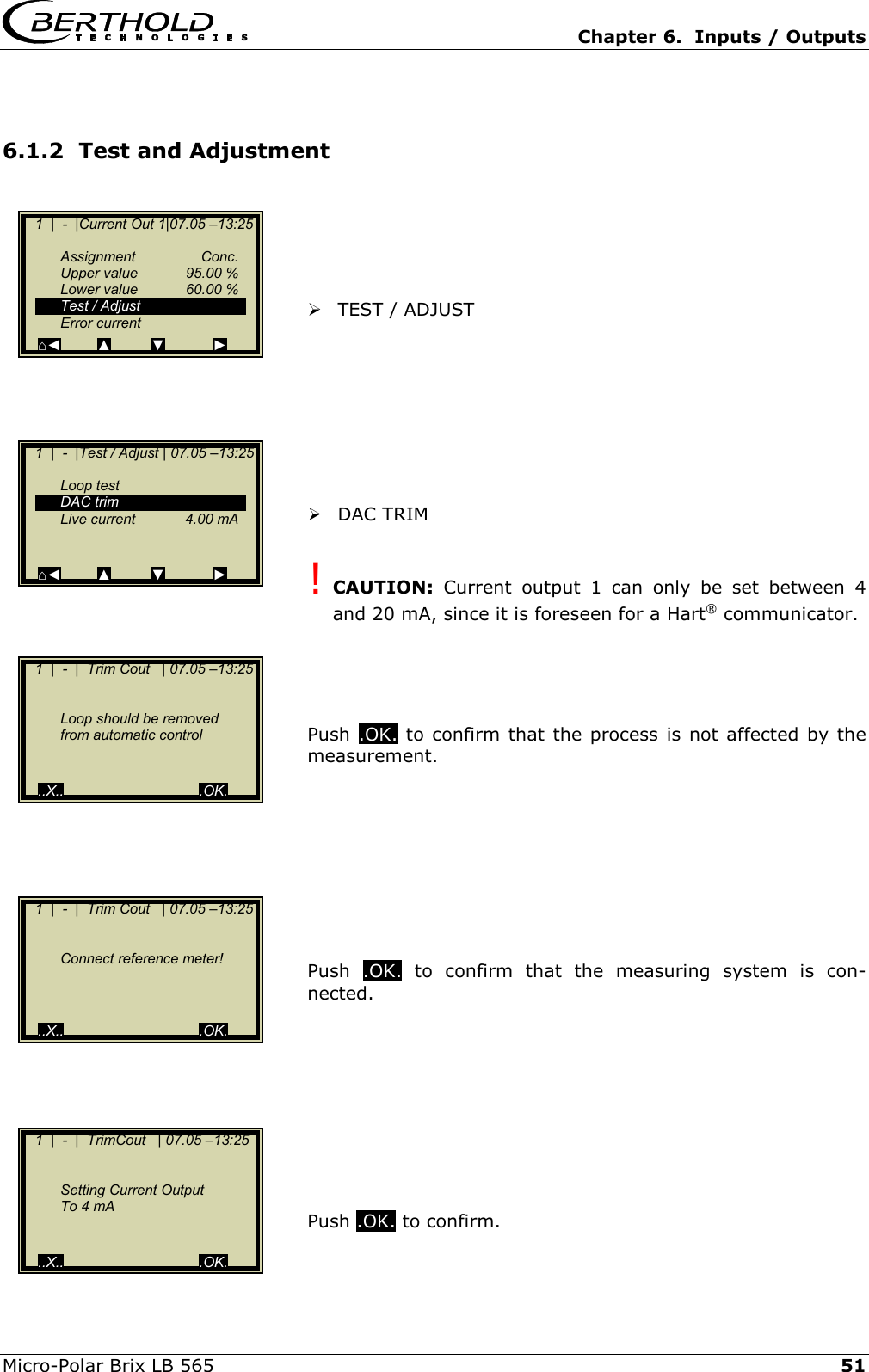
![Chapter 6. Inputs / Outputs Micro-Polar Brix LB 565 59 6.3.2 Pt 100 Calibration TRIM Pt 100 ..OK.. Connect 100 Ohm resistor to the Pt100 terminals [11] [23]. Confirm once more with .O.K.. Adjustment of lower point finished. After connection of the resistor, confirm with ..OK... 1 | - | Pt 100 | 07.05 –13:25 Enabled yes Trim Pt 100 Pt 100 live ⌂◄ ▲ ▼ ► 1 | - |Trim Pt 100 | 07.05 –13:25 Connect 100 Ohm resistor to Pt 100 terminals ! (for 0°C / 31.4°F adjustment) ..X.. .OK. 1 | - |Trim Pt 100 | 07.05 –13:25 100 Ohm resistor connected? ..X.. .OK. 1 | - |Trim Pt 100 | 07.05 –13:25 Lower point adjusted ..X.. .OK. 1 | - |Trim Pt 100 | 07.05 –13:25 Connect 138,5 Ohm resistor to Pt 100 terminals ! (for 100°C / 211.4°F adjustment)](https://usermanual.wiki/Berthold-Technologies/FCC01X01/User-Guide-585001-Page-125.png)