Berthold Technologies FCC01X01 Moisture Measuring System User Manual
Berthold Technologies Moisture Measuring System
User Manual
Process Control
Concentration Meter
Micro-Polar Brix LB 565
Hardware Manual
ID No. 39531 BA2
Rev. No.: 00 01/11/04
Soft. Version: 1.00
detect and identify
User’s Guide

The units supplied should not be repaired by anyone other than Berthold Service
engineers or technicians authorized by Berthold.
In case of operation trouble, please address our central service department.
The complete user’s guide consists of two manuals, the hardware description and the software
description.
The hardware manual comprises:
mechanical components
assembly
electrical installation
technical data
electrical and mechanical drawings
The software manual comprises:
operation of the evaluation unit
parameter description
basic setting
calibration
error messages
The present manual is the hardware description.
Subject to change without prior notice.

Table of Contents
Micro-Polar Brix LB 565 5
Table of Contents
Page
Chapter 1. Safety Summary 7
1.1 Symbol and Pictograms 7
1.2 Use and Function 8
1.3 General Safety Instructions 10
Chapter 2. General Information 13
2.1 Intended Use 13
2.2 Definitions 14
Chapter 3. System Description 15
3.1 Principle of Measurement 15
3.2 Calculation of Measured Values 16
3.3 Temperature Compensation 17
3.4 Mechanical Components 19
3.4.1 The Evaluation Unit 20
3.4.2 The Microwave Probes 22
3.4.3 High-frequency Cable 25
3.5 Measurement Configuration 26
Chapter 4. Getting Started 27
4.1 Transport to the Installation Site 27
4.2 Installation 27
4.2.1 Pan Probe Installation 27
4.2.2 Setting up the Evaluation Unit 29
4.3 Connecting the Evaluation Unit 30
4.3.1 Connecting the HF Cable 30
4.3.2 Pin Configuration of the Connector Strip 32
4.3.3 Digital Outputs, Relays 37
Chapter 5. Service Instructions 38
5.1 General Information 38
5.2 Instrument Cleaning 38
5.3 Batteries 38
5.4 Fuse Replacement 39
Chapter 6. Technical Data 40
6.1 Evaluation Unit 40
6.2 Probes 43
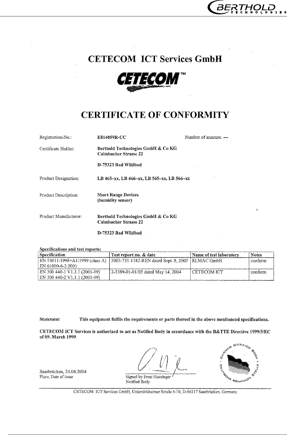
Chapter 7. Certificate 44
7.1 EC-Declaration of Conformity 44
7.2 Frequency approval 45
Chapter 8. Engineering drawings 47
8.1 Dimensional drawing for housing 47

Table of Contents
Micro-Polar Brix LB 565
6
8.2 Electrical Wiring Diagram 48
8.3 Dimensional drawings for batch pan probes 49
8.3.1 Type LB 5650-01 49
8.3.2 Type LB 5650-02 50
8.3.3 Type LB 5650-03 51
8.3.4 Type LB 5650-04 52
8.3.5 Type LB 5650-05 53
8.4 Dimensional drawings for continuous pan probes 54
8.4.1 Type LB 5651-01 54
8.4.2 Type LB 5651-02 55
8.4.3 Type LB 5651-03 56
8.4.4 Type LB 5651-04 57
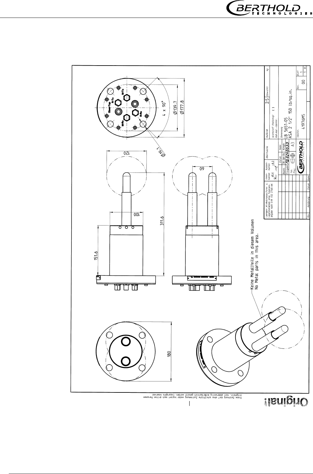
8.4.5 Type LB 5651-05 58
8.5 Installation sheets for LB 5650 (Batch pan probes) 59
8.6 Installation sheets for LB 5651 (Continuous pan probes) 61
Chapter 1 Safety Summary
Micro-Polar Brix LB 565 7
Chapter 1. Safety Summary
1.1 Symbol and Pictograms
The following symbols identify safety instructions in this user’s
guide:
Danger!
Possible danger of life and health hazard
Caution!
Possible hazard
Minor personal injuries
Warning!
Possible hazard
Property damages
Note!
Tips for application and useful information
The safety instructions are supplemented by explanatory picto-
grams, for example:

Chapter 1 Safety Summary
Micro-Polar Brix LB 565
8
1.2 Use and Function
The Micro-Polar fulfils the regulations of FCC1, Part 15 and the
regulations of the Canadian Industry according to RSS-210. This
measuring system complies with interference immunity and radi-
ated interference and is permissible for operation.
“IC2:” before the equipment certification number signifies that the
Industry Canada technical specifications were met. It does not
guarantee that the certified product will operate to the user’s satis-
faction.
The Micro-Polar Brix complies with the R&TTE regulations
1999/5/EG and fulfils herein all requirements for such high fre-
quency systems. The Micro-Polar Brix contains the identification of
conformity according to CE symbol of No. 0682 of the certification
office. The certificate can be found in chapter 7.2 Frequency ap-
proval.
1 FCC … Federal Communications Commission
2 IC ... Industry Canada
Frequency-
Approvals
FCC-
Approval Sign
Chapter 1 Safety Summary
Micro-Polar Brix LB 565 9
Note!
The Micro-Polar Brix is a system for concentration measurement
using microwave technology. The microwave probe is immersed
into the product being measured. The emitted microwaves have a
very low power (< 0.1 mW) and are, therefore, not at all hazard-
ous to human beings or the environment. Also, the product is not
altered at all.
Danger!
The Micro-Polar Brix has been manufactured in compliance with
the safety requirements for microwave devices. If special legal
provisions exist regarding the use of microwaves, it will be the
responsibility of the user to adhere to them.
Any change in frequency or any other manipulation on the micro-
wave device will result in a loss of the frequency license and will
be prosecuted.
The microwave modules do not include any replaceable compo-
nents and must not be opened.
Chapter 1 Safety Summary
Micro-Polar Brix LB 565
10
1.3 General Safety Instructions
Note!
The Micro-Polar Brix has been manufactured in accordance with
the best available technology and in compliance with acknowl-
edged safety rules to ensure the highest level of occupational
safety.
The instrument housing is protected according to protection type
IP 65 and is suitable for outdoor application. The instrument has
been tested by the manufacturer and is delivered in a condition
that allows safe and reliable operation.
Caution!
The safety instructions and warnings in this user’s guide have to
be observed without fail to ensure safe operation of the instru-
ment!
The system may only be used in technically good order and only
according to regulations!
Only authorized persons may work with the system who have
been assigned to do this and who have the proper qualification
and have received the necessary instructions!
Installations and modifications on the system which could affect
the operational safety are not permitted!
Warning!
Ambient conditions:
All system components require non-corrosive ambient conditions
during transport, storage and starting up.
Chapter 1 Safety Summary
Micro-Polar Brix LB 565 11
Danger!
Electrical shock hazard:
Disconnect power to ensure that contact with live part is avoided
during installation and when servicing.
Disconnect power before opening the instrument. Work on open
and live instruments is prohibited.
Warning!
Spare fuses must match the rating specified by the device manu-
facturer. Short-circuiting or manipulation is not permitted.
Warning!
The LB 565 and all ancillary units have to be connected to mains
via grounded connection.
Caution!
If liquid gets inside the instrument, cut off the power supply. The
instrument has to be checked and cleaned by an authorized ser-
vice center.
Warning!
Never change the installation and the parameter settings without
full knowledge of these operating instructions, as well as full
knowledge of the behavior of the connected controller and the
possible influence on the operating process to be controlled.

Micro-Polar Brix LB 565
12

Chapter 2 General Information
Micro-Polar Brix LB 565 13
Chapter 2. General Information
2.1 Intended Use
The measuring system LB 565 can be used to determine the con-
centration of nearly all materials which can be dissolved or sus-
pended in water using microwave technology. Pan probes with and
without rinsing device are available.
The pan probes have been designed for installation in pipelines
with a nominal width of ≥ 200 mm and in containers, for example,
evaporation crystallizers. The probe is installed so that both meas-
uring rods (sender and receiver) are immersed into the product
being measured.
During operation, the concentration meter Micro-Polar Brix sends
out electromagnetic radiation in a frequency range between 2.4
GHz and 2.5 GHz (range restrictions depend on local regulations in
your Country). The microwaves emerge only between both meas-
uring rods of the probe, and are not dangerous to human beings
and the environment (power emission < 0.1 mW). The microwaves
are emitted targeted from the microwave window; the product is
not altered by the microwaves.
To ensure proper function of the meter, please pay attention to the
following:
Note!
The material being measured must not be electrically conduc-
tive, i.e. the ohmic resistance is infinite.
The product must not contain any gas bubbles, or gas bubbles
have to be compressed with adequate pressure when carrying
out measurements in pipelines.
The ion concentration, e.g. salt content, has to be near con-
stant.

Chapter 2 General Information
Micro-Polar Brix LB 565
14
2.2 Definitions
Attenuation Weakening of the microwave signals, microwaves measurement
effect.
Batch pan probe Pan probe without rinsing device. Application e.g. in evapora-
tion crystallization process.
Continuous pan
probe
Pan probe with rinsing device. Application e.g. in continuous
evaporation crystallization process.
Factory setting All parameters have been set by the manufacturer using stan-
dard values. In most cases this simplifies calibration of the in-
strument significantly. Despite factory setting, calibration al-
ways has to be performed.
HF cable High-frequency cable.
Microwaves Term for electromagnetic waves in a certain frequency range.
Phase Phase or phase shift. Microwave measurement effect.
Quad cable Combination of four HF cables of equal length in a corrugated
tube.
Softkeys Buttons associated with the software.
TC Temperature compensation.
Chapter 3 System Description
Micro-Polar Brix LB 565 15
Chapter 3. System Description
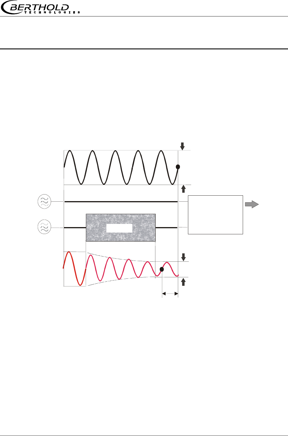
3.1 Principle of Measurement
The microwaves that spread between the rods transmit the prod-
uct being measured; their propagation speed is slowed down (=
phase shift) and their intensity is damped (= attenuation). Figure
1 illustrates the principle of measurement: The propagation speed
of microwaves passing through the product being measured is
slowed down (phase shift) and their intensity (attenuation) is re-
duced, relative to a reference signal.
Prerequisite is that the product being measured shows some di-
electric properties. In sugar strike, it is the water which presents a
very distinct dielectric fluid. The water or dry mass concentration
can therefore be determined by measuring the phase shift and/or
attenuation.
The concentration to be detected in the product depends in good
approximation linear on phase shift and attenuation. For this rea-
son we can measure the concentration or the dry mass content of
the sugar solution using a linear calibration (see chapter 3.2
Calculation of Measured Values).
Figure 1:
Schematic diagram:
Change of microwave
by product
Phase shif
t
Product
Phase comparison
--> Phase
A
mplitude comp.
--> Attenuation
Reference path
Reference signal
Measurement signal
Measured value:
Concentration %TS
HF sources
Sende
r
Receive
r

Chapter 3 System Description
Micro-Polar Brix LB 565
16
3.2 Calculation of Measured Values
The microwave parameters phase and attenuation are calibrated
according to the plausibility analysis.
Linear calibration:
CDBAK +⋅+
ϕ
⋅=
Quadratic calibration:
(
)
()
(
)
()
CDargDBDBargAAK 2
21
2
21 +⋅⋅+⋅+ϕ⋅ϕ⋅+ϕ⋅=
K Concentration
A, B, C Coefficients of respective calibration function
ϕ Phase
D Attenuation
ϕ, D Rate of phase, attenuation
()
ϕarg ,
()
Darg algebraic sign of phase, attenuation
The formula is simplified accordingly for a pure phase or attenua-
tion measurement.
In case of varying measurement parameters (product density,
temperature, etc.), the microwave phase shift method yields a
much better accuracy compared to the microwave attenuation
method. The phase measurement is significantly less affected by
material parameters such as temperature or salt contents (electro-
lytic conductivity), bubbles and grain size than an attenuation
measurement.
Note!
In most cases we recommend using a pure phase measurement
to determine the concentration of sugar strike. It is calculated in
good approximation through linear calibration:
CAK +
ϕ
⋅=
Micro-Polar Brix allows you to calibrate, display and output two
concentrations K1 and K2. You have to enter the calibration coeffi-
cients separately for concentration 1 and 2. For more information
please refer to the Software Manual.

Chapter 3 System Description
Micro-Polar Brix LB 565 17
3.3 Temperature Compensation
Temperature compensation (TC) has to be carried out if varying op-
erating states are likely to occur, for example vapour pressure and
product temperature. TC has to be carried out whenever you are
working with cooling crystallizers. The following formulas are used
for temperature compensation.
Linear compensation
Additive: θ∆⋅+ϕ=ϕ ϕ
TC
meascomp
θ∆⋅+= Dmeascomp TCDD
Multiplicative: )TC(
meascomp θ∆⋅+ϕ=ϕ ϕ
1
)TC(DD Dmeascomp θ∆⋅+= 1
Quadratic compensation
Additive:
()
θ∆⋅
θ∆⋅+θ∆⋅+ϕ=ϕ ϕϕ argTCTC
meascomp
2
21
()
θ∆⋅
θ∆⋅+θ∆⋅+= argTCTCDD DDmeascomp
2
21
Multiplicative:
()
)argTCTC(
meascomp θ∆⋅
θ∆⋅+θ∆⋅+ϕ=ϕ ϕϕ
2
21
1
()
)argTCTC(DD DDmeascomp θ∆⋅
θ∆⋅+θ∆⋅+= 2
21
1
Where
ϕmeas = measured phase [°]
ϕcomp = compensated phase [°]
Dmeas = measured attenuation [dB]
Dmeas = compensated attenuation [dB]
TCϕx = temperature coefficient [° / °C]
TCDx = temperature coefficient [dB/ °C]
∆θ = measured temperature (Tmeas ) – reference temp. (TRef)
θ∆ = difference temperature
()
θ∆arg = algebraic sign of difference temperature
Depending on the selected function (additive, multiplicative, quad-
ratic, cubic), the required temperature coefficients appear on the
Calibration menu. Temperature coefficients that are not used are
set to zero.

Chapter 3 System Description
Micro-Polar Brix LB 565
18
If you select two-range calibration (split concentration), separate
TC’s have to be entered for both concentration ranges. The coeffi-
cients are entered in the course of calibration.
TC can be carried out via Pt100 or via current input. This has to be
defined on the Calibration menu. The Pt100 temperature range is
between –50 °C and +200 °C.
How to work with the temperature compensation is described in
detail in the Software Manual.
Note!
In the most cases, linear multiplicative temperature compensation
in good approximation is the correct mode of calculation, e.g. for
cooling crystallizers.
Chapter 3 System Description
Micro-Polar Brix LB 565 19
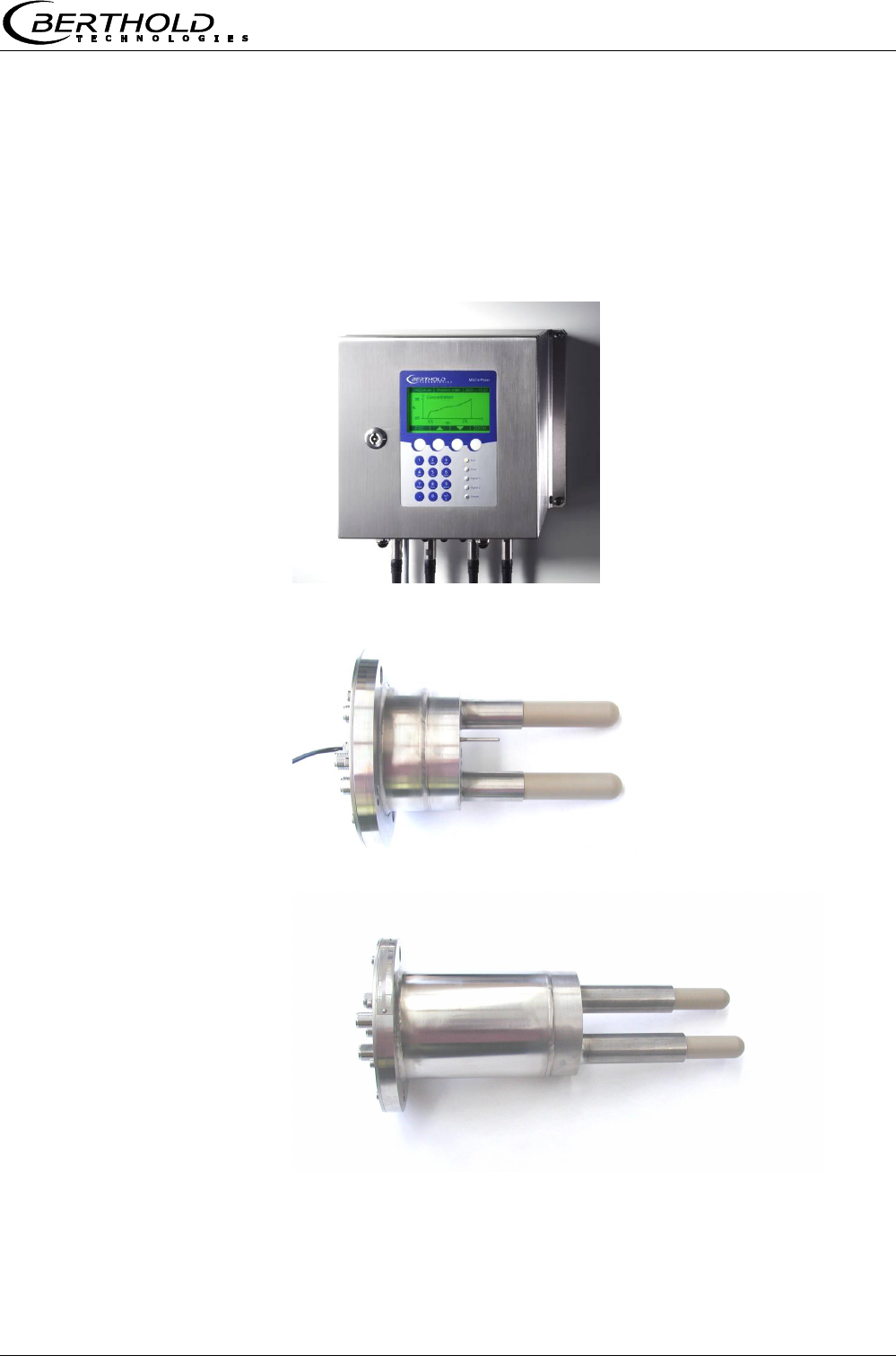
3.4 Mechanical Components
The measuring system comprises an evaluation unit (see Figure
2), one probe and one set of special high-frequency (HF) cables.
The probes are available in different versions, as pan probe with
and without rinsing device (see Figure 3 and Figure 4).
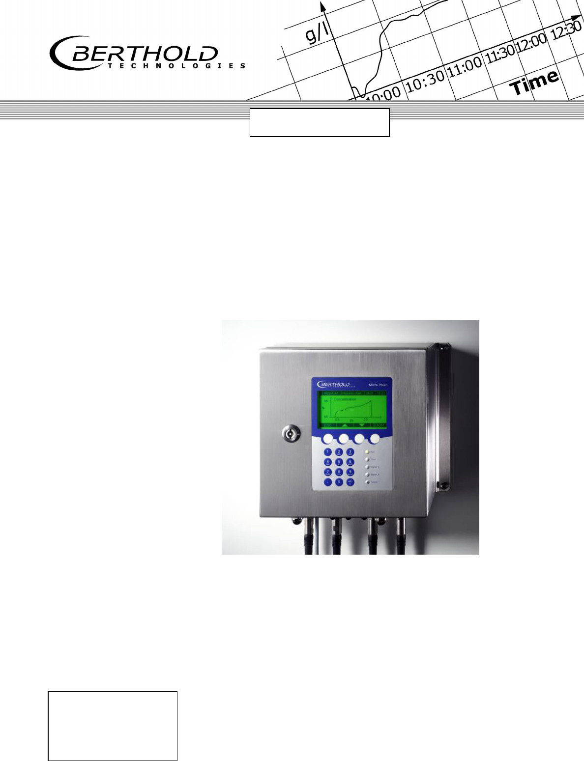
Figure 2:
Evaluation unit
Micro-Polar Brix LB 565
Figure 3:
Batch pan probe LB 5650
Figure 4:
Continuous pan probe
LB 5651
Chapter 3 System Description
Micro-Polar Brix LB 565
20
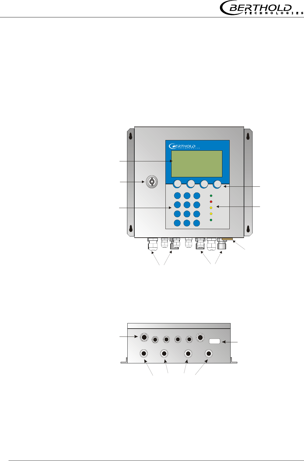
Cable feed-through
M 20 and M 16
High-frequency connections
RS232
9-pole Sub-D-connector
M-TxM-Rx R-Tx R-Rx
and cable feed-through
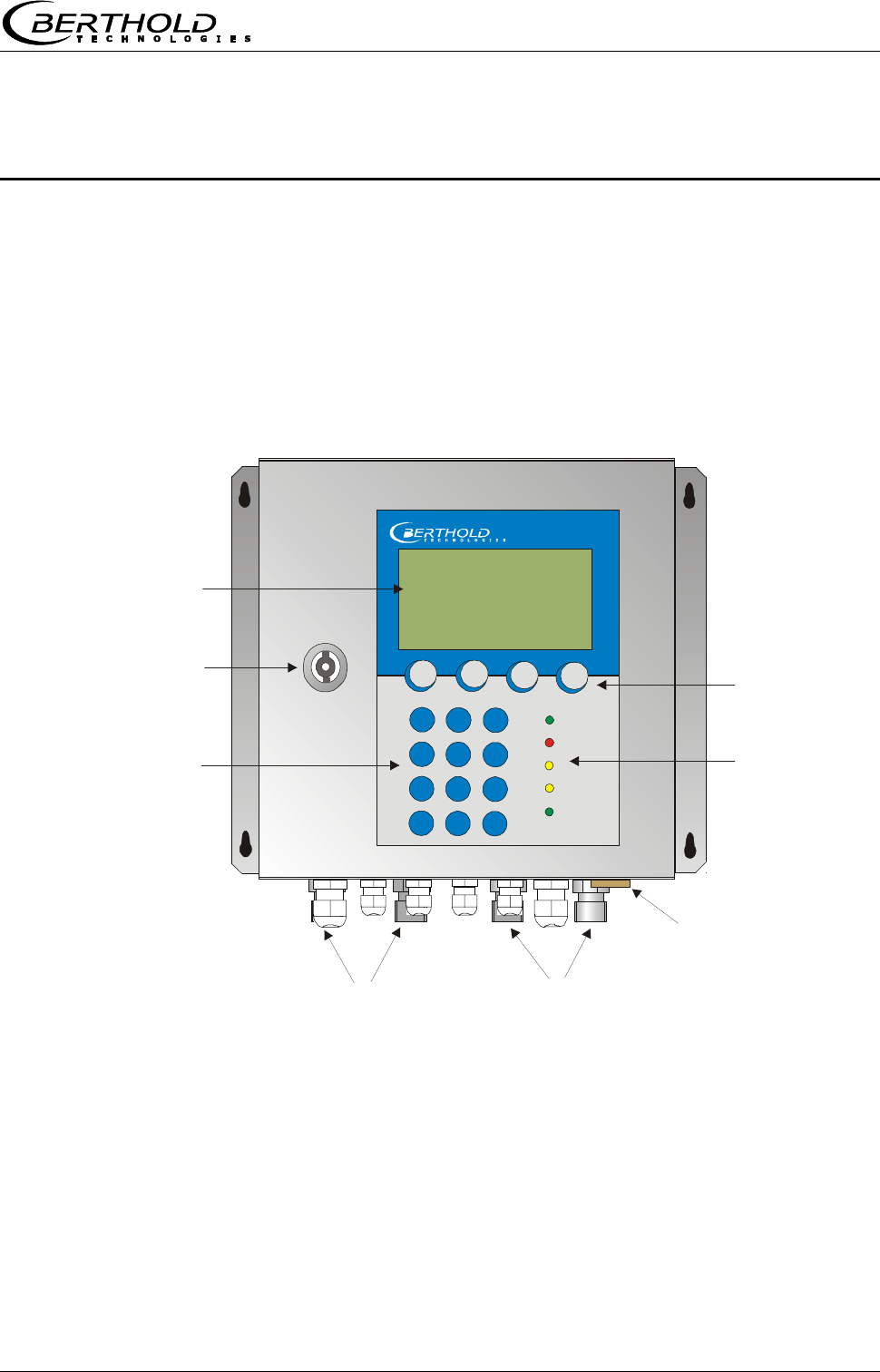
Lock
Numerical
keypad
Softkey buttons
LED’s
LCD display
RS232 connection
HF connections for
signal cable reference cable
Micro-Polar
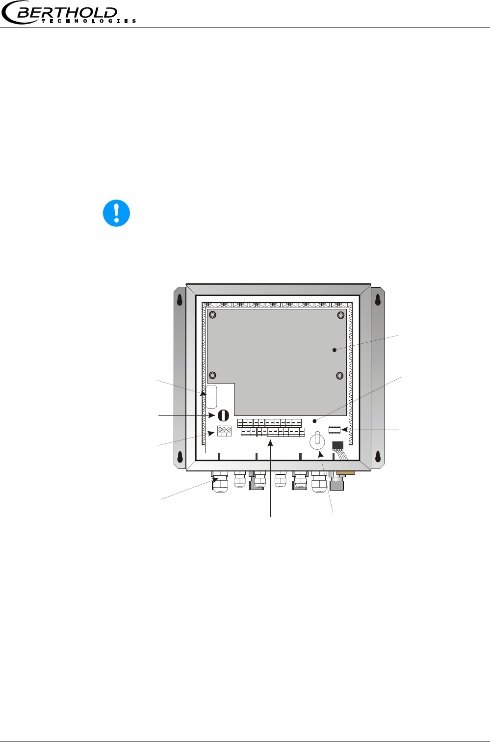
3.4.1 The Evaluation Unit
The evaluation unit comprises the evaluation computer with mi-
crowave unit. The microwaves are generated, received and ana-
lyzed in the microwave unit. Signal processing and communication
take place in the evaluation computer. For simple operation, the
measuring system includes a display, 4 softkeys and an alphanu-
meric keypad. Different functions are assigned to the softkeys on
the display.
An RS232 interface is included on the underside of the instrument.
Figure 5:
Front view of
evaluation unit
Figure 6:
Evaluation unit -
Bottom view
Chapter 3 System Description
Micro-Polar Brix LB 565 21
LED’s on the Front Panel
Five LED’s on the instrument front panel indicate the instrument
status.
Figure 7:
LED’s on the front panel
Run
Error
Signal 1
Signal 2
Comm
LED Function
Run Instrument in measurement mode
A flashing LED indicates an error
Error Error
Cancelled after reset or if error has been elimi-
nated
Signal 1 Display depending on the selected function of
relay 1, possible functions: error, no product,
alarm min., alarm max., measurement stopped
Signal 2 Display depending on the selected function of
relay 2, possible functions: error, no product,
alarm min., alarm max., measurement stopped.
Comm Communication active, e.g. via RS 232 or RS
485
Terminal Block
The electrical connections of the LB 565 are located on a connector
strip in the wall housing. The terminal block is accessible from the
front after you have opened the cover. There, you also find the
power cut-off switch and the fuse. The high-frequency connections
are located on the outside of the housing. All other elements, es-
pecially the live elements (on the motherboard) are provided with
a protection cap.
Chapter 3 System Description
Micro-Polar Brix LB 565
22
3.4.2 The Microwave Probes
The pan probe is available in two different versions: with and with-
out rinsing device (see Figure 8). For technical data please refer to
chapter 8. Technical Data.
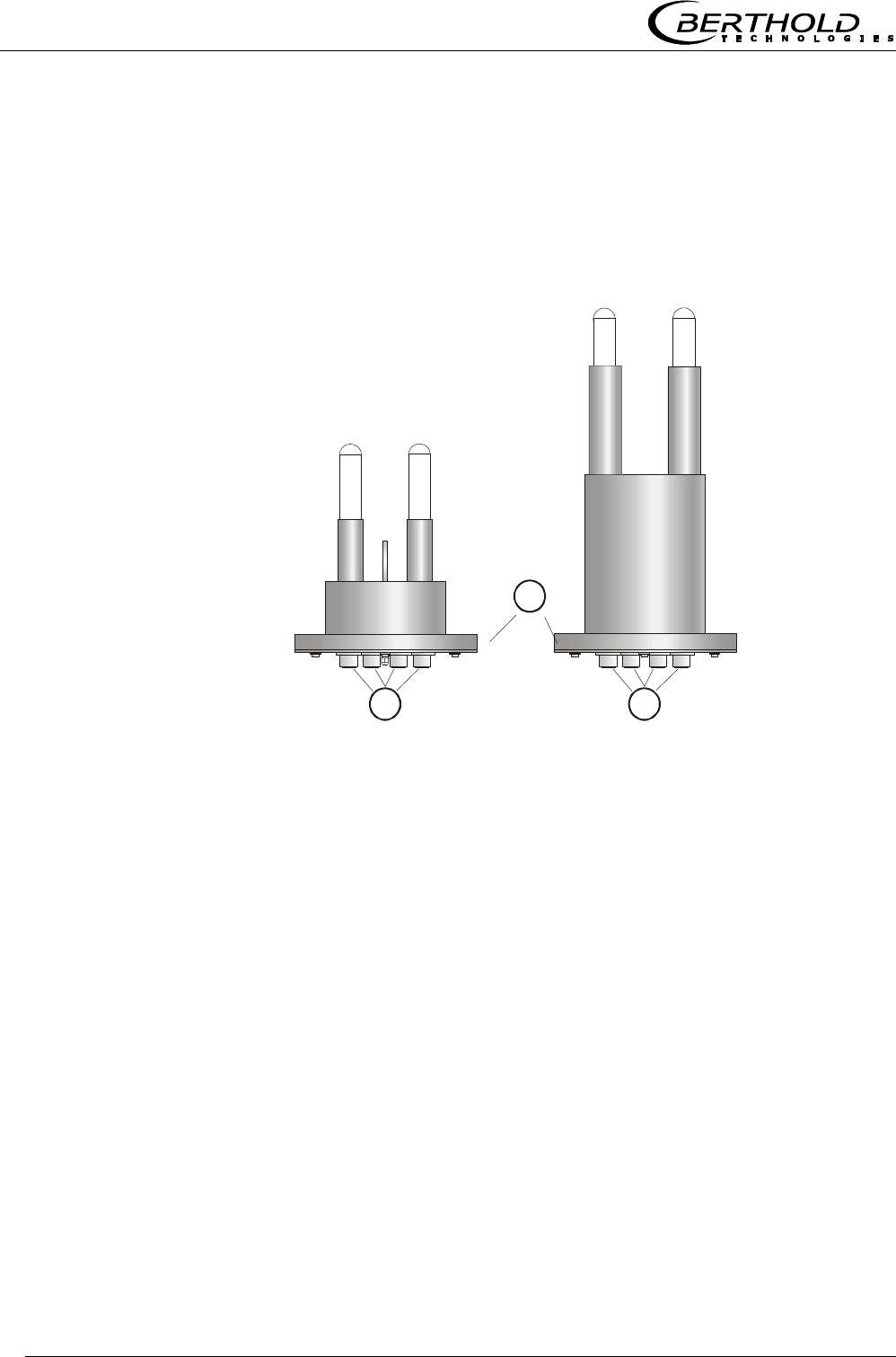
Figure 8:
Pan probe
A
LB 5650
without rinsing device
A
B
LB 5651
with rinsing device
A: High-frequency connections
B: Process connection, flanges of different sizes
Pan Probe Type LB 5650 and Type LB 5651
The pan probe has been specially designed for concentration
measurements in containers. Both measuring rods are immersed
into the product. The microwaves are emitted from one end of the
rod and received at the other end of the rod; they are emitted only
in the direction of the opposite end of the rod. This direction char-
acteristic of the probe minimizes the interfering influence of metal
parts in the vicinity of the probe and allows installation if only little
space is available. For example, the concentration of sugar strike
can be measured continuously to find the suitable inoculation time.
The plastic rods meet the special requirements for application in
food.
Two different probe types are available:
the "batch pan probe" is used for discontinuous crystallization
processes
Chapter 3 System Description
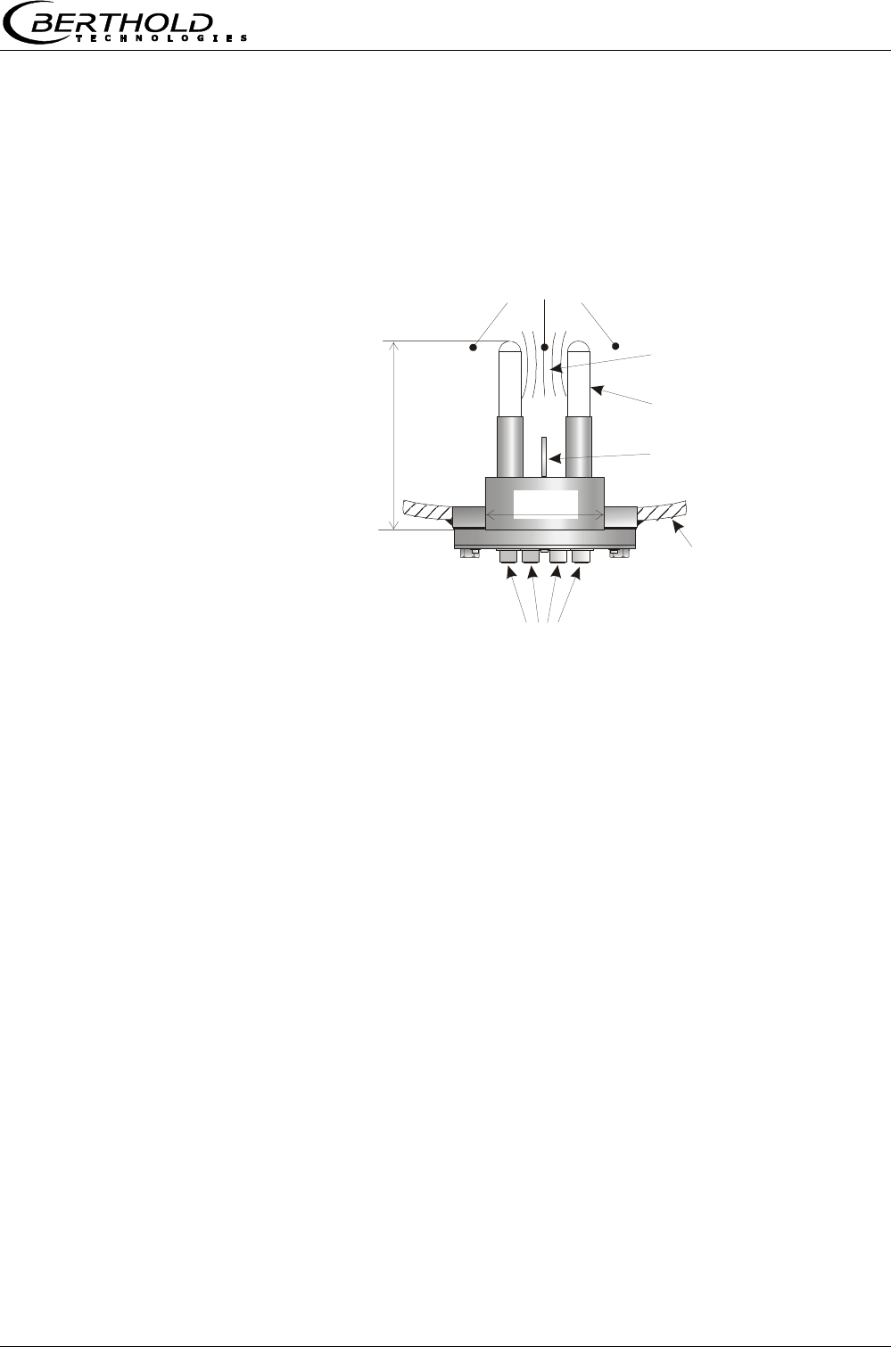
Micro-Polar Brix LB 565 23
Container wall
HF connections
Product
Microwave
measuring field
Plastic rods
~ 190 mm
100 mm
Pt100
the "continuous pan probe" with rinsing device is used for con-
tinuous crystallization processes; this type of probe prevents
crystallization on the microwave exit windows and therefore
provides exact measurement results.
The flow direction of the product being measured should be verti-
cal, as shown in Figure 9. This ensures a representative product
between the measuring rods, provided it is mixed thoroughly.
Figure 9:
Batch pan probe LB 5650
PT-100 Only the batch pan probe is provided with a PT-100 and is con-
nected to the evaluation unit via a 4-wire cable. The wiring dia-
gram for the PT-100 is described in chapter 4.3.2 Pin Configura-
tion of the Connector Strip. Usually, no temperature compensa-
tion is required for measurements with the continuous pan
probe; therefore, the continuous pan probe is not equipped with
a PT 100.
Chapter 3 System Description
Micro-Polar Brix LB 565
24
Pan Probe Type LB 5651 with Rinsing Device
The probe LB 5651 with rinsing device has been designed for
measurements in continuous crystallization processes. The con-
tinuous pan probe can be used, for example, for sugar manufac-
turing, in the afterproduct, raw sugar and white sugar.
The continuous pan probe has two rinsing channels which keep the
plastic rods free from incrustations; this ensures that the micro-
waves come into direct contact with the product being measured.
All parts coming into contact with the product meet the specific
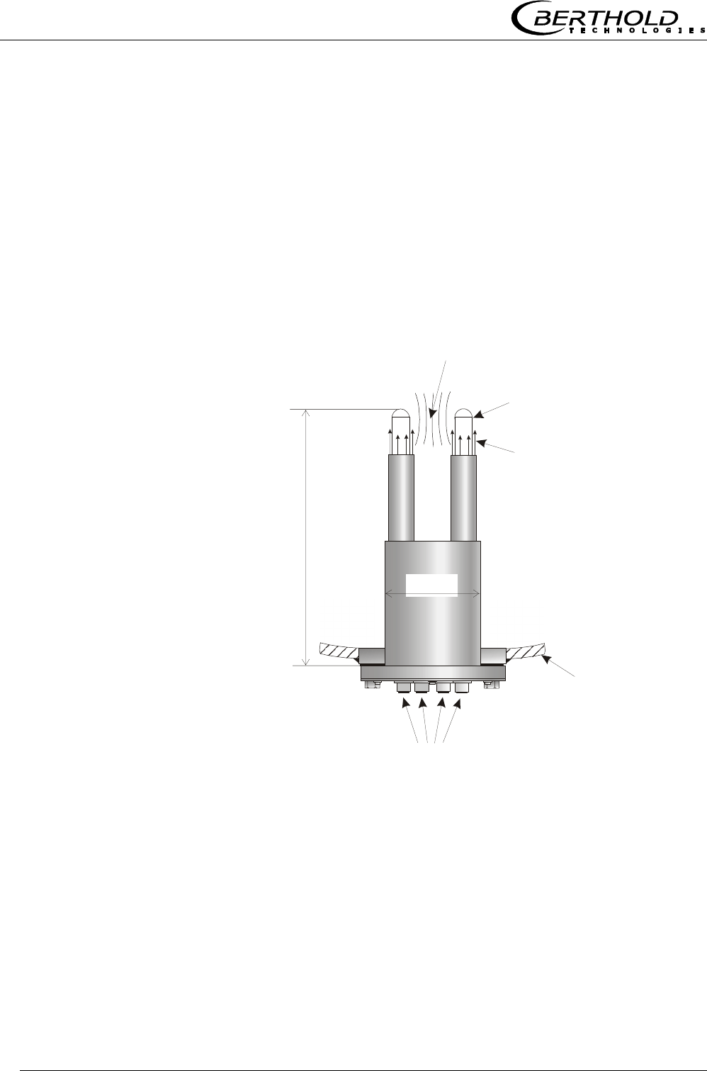
requirements for application in foodstuffs. Figure 10 shows the
design of the probe.
Figure 10:
Continuous pan probe
LB 5651
Container wall
4 x HF connections
2 x 3/8’’ Rinsing connections, internal thread
Microwave
measuring field
Plastic rods
Rinsing medium
~ 320 mm
100 mm
Chapter 3 System Description
Micro-Polar Brix LB 565 25
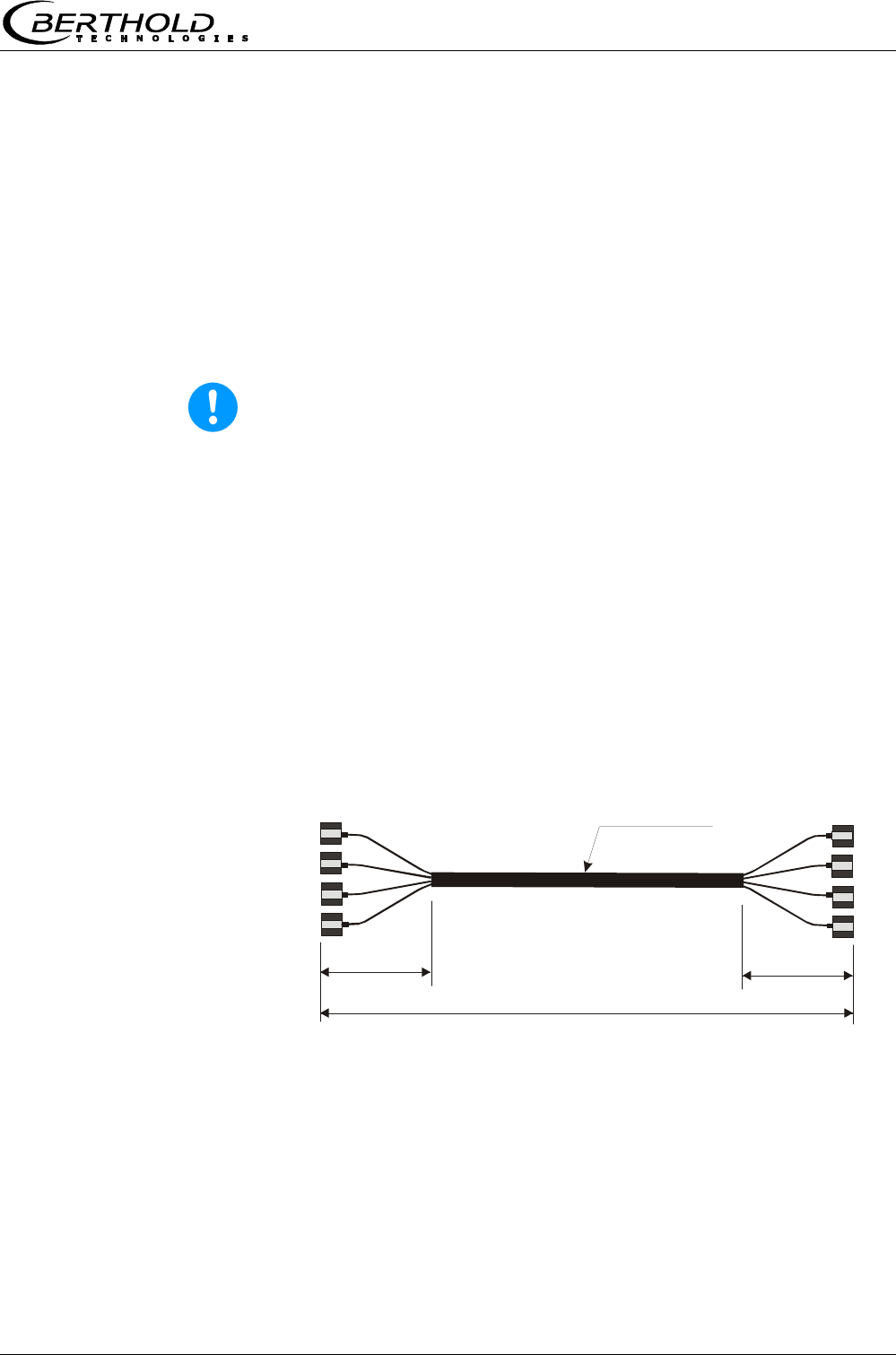
Lengths 2, 6, 10 m
Corrugated tube
ø
18.5 mm
0.35 m 0.35 m
4 x N-connector
4 x N-connector
3.4.3 High-frequency Cable
High-frequency cables (HF cable) are used to transmit microwaves
between probe and evaluation electronics. The measuring system
includes a HF quad cable, see Figure 11. The quad cable comprises
four individual HF cables of equal length whose ends are termi-
nated by an HF connector (N-type).
However, these high-quality special cables are rugged and tem-
perature-resistant only to a certain degree.
Warning!
Never bend HF cables! The bending radius should not be less than
100 mm. After installation, fix cables with cable binders.
HF cables change the conductivity (of microwaves) depending on
the temperature. Therefore, they would create measurement er-
rors if the ambient temperature varies. This error is compensated
for by enabling the cable compensation. The influences of the am-
bient temperature on the signal cable are compensated for by
means of the reference cable. The reference cable has the same
length as the signal cable; during operation, it should be exposed
to the same ambient temperature. We, therefore, recommend in-
stalling both cable types together in a corrugated tube; this also
simplifies installation.
Figure 11:
Quad cable
Chapter 3 System Description
Micro-Polar Brix LB 565
26
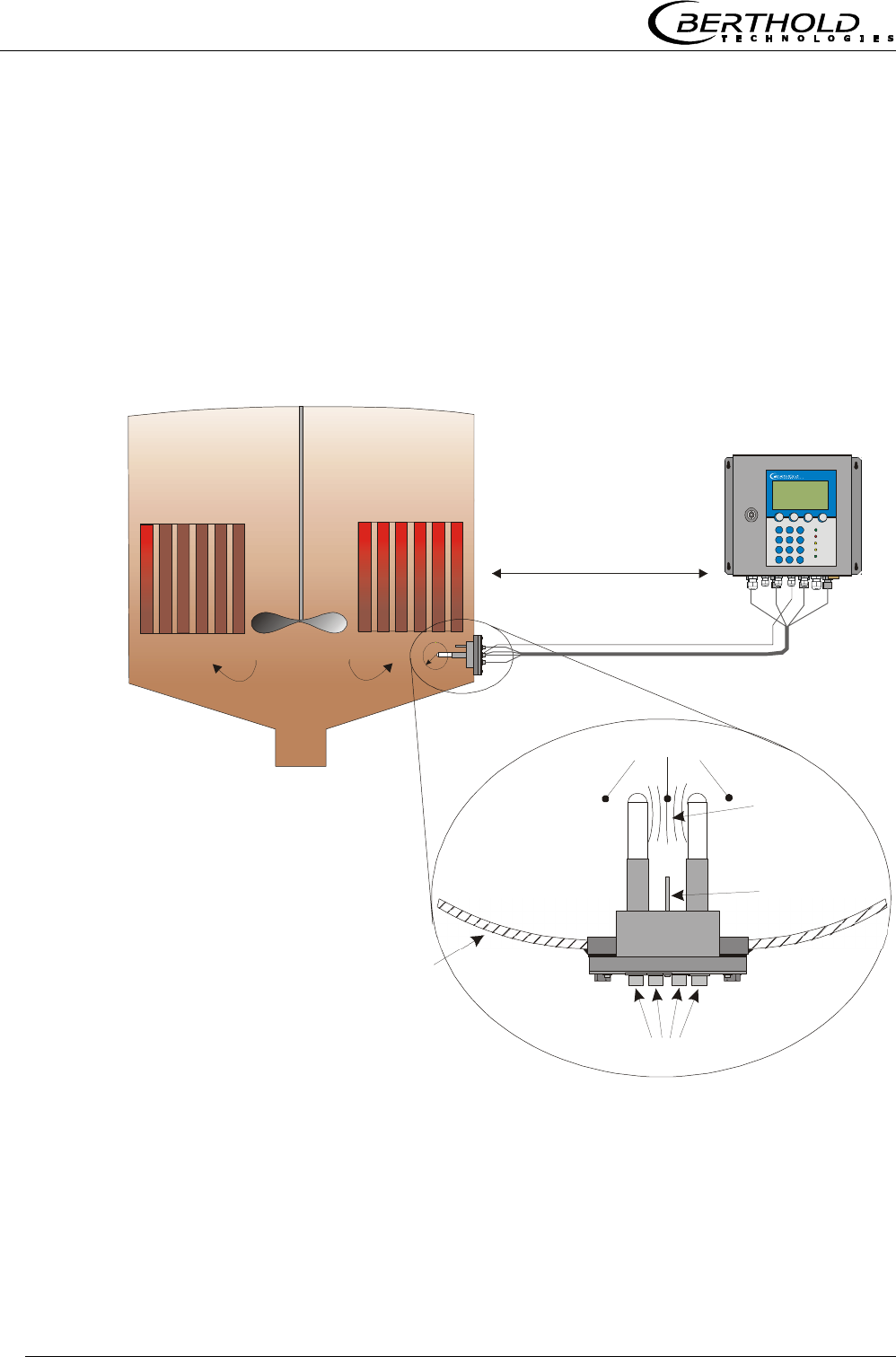
3.5 Measurement Configuration
The evaluation unit is connected to the microwave probe via HF
quad cable. Cable lengths of up to 10 m allow you to place the
evaluation unit in a sufficient distance to the evaporation appara-
tus to rule out any influence by the radiation heat.
The pan probe is connected using a HF quad cable, with two indi-
vidual cables making up the signal and the reference channel.
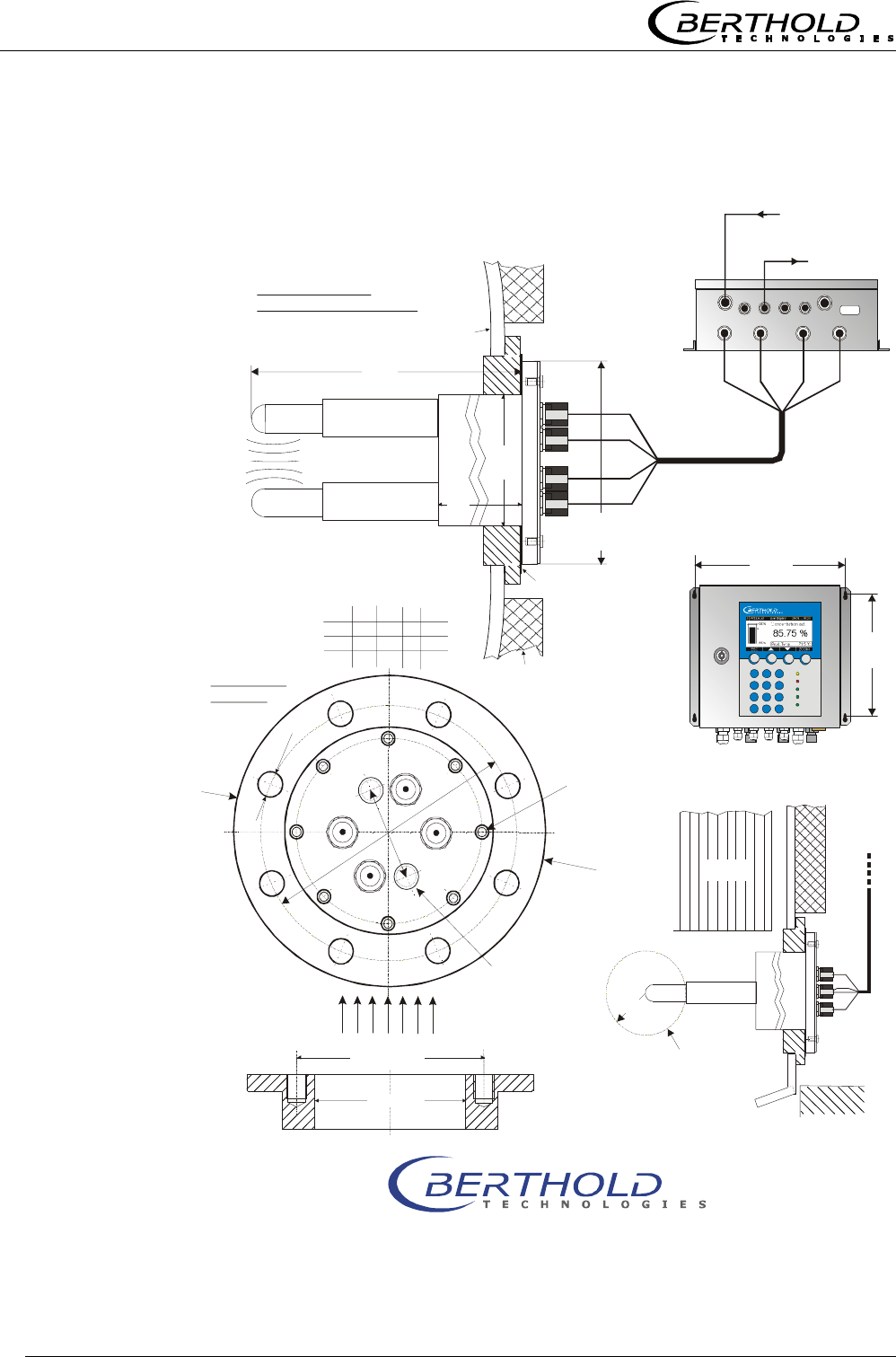
Our example below (Figure 12) shows the measurement configura-
tion on a discontinuous evaporation crystallizer.
Figure 12:
Typical system
configuration of an
evaporation crystallizer
Container wall
Distance up to 10 m
(no radiation heat)
a
Micro-Polar
Pt100
HF connections
Product
Microwave
measuring field
PT-100
HF quad cable

Chapter 4 Getting Started
Micro-Polar Brix LB 565 27
Chapter 4. Getting Started
4.1 Transport to the Installation Site
Warning!
Risk of damage!
System parts may get damaged during transportation!
Transport probe and the evaluation unit in their original packag-
ing. Protect parts against shocks.
Especially the plastic rods of the pan probes have to be protected
against mechanical impact!
After unpacking, make sure all parts listed on the packing list have
been delivered and show no sign of damage; if necessary, clean
these parts.
If you detect any damage, please notify the forwarder and the
manufacturer immediately.
4.2 Installation
4.2.1 Pan Probe Installation
Figure 12 shows the position of the batch pan probe on the con-
tainer. This position is equally valid for the continuous pan probe.
The installation sheet in chapter 8 includes all information required
for installation.
For installation, please keep in mind:
Select the installation site such that good mixing and a homo-
geneous product is ensured and the formation of bubbles on
the probe is prevented. A tap should be provided in the direct
vicinity to allow representative sampling.
Chapter 4 Getting Started
Micro-Polar Brix LB 565
28
The probe has to be flange-mounted on the container such that
the product being measured flows between both measuring
rods. In other words, the fork (both measuring rods) has to be
arranged vertically to the material flow (e.g. sugar strike).
The distance between the measuring rod tips and any metal-
lized walls (heating element, stirrer, container wall) should be
at least a = 60 mm.
For installation of the probe you need a hole diameter in the
connection flange of at least ∅
∅∅
∅ 102 mm.
For further installation dimensions please refer to chapter 8
(see installation sheets).
Rinse Parameters (only with continuous pan probe)
The sugar quality or purity is essential for the rinse parameters,
i.e. rinse frequency and duration. The rinse parameters may
change with the purity of the solution and have to be adapted, in
individual cases, to the product and the crystallization process.
The following typical rinse parameters are used:
Frequency Every 2 hours
Duration 12 seconds
Rinse solution Water, condensate
Temperature of
rinse solution
Average product temperature,
typically 65 ±5°C
Pressure ≥ 3 bar, max. 8 bar
Connections 2 x 3/8 inch (female screw thread)
Supply pipe ≥ 1/2 inch
The rinse connections can be rinsed at the same time or one after
the other. The above rinse parameters have to be observed for
each connection.
Note!
The required rinse duration has to take into account a possible
inertness of the system, e.g. valve openings. The rinse supply
pipes have to be insulated well against heat, in order to prevent
an initially colder rinse solution.
Rinse parameters
Chapter 4 Getting Started
Micro-Polar Brix LB 565 29
4.2.2 Setting up the Evaluation Unit
For installation of the evaluation unit please keep in mind:
Position the evaluation unit depending on the length of the HF
cable in the vicinity of the microwave probe. The HF cable is
available in a length of 2, 6 and 10 m; the standard cable
length is 2 m.
The instrument has to be protected against vibrations.
For instrument installation you should foresee a cutoff device to
allow you to disconnect the meter easily and quickly from the
power supply.
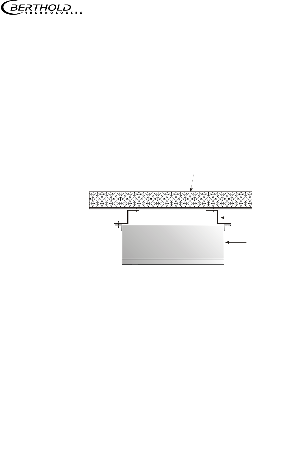
When installing the evaluation unit on an evaporation crystal-
lizer, you should use a distance rail to minimize the thermal
radiation and conduction. See Figure 13
Figure 13:
Top view:
Installation
of evaluation unit on the
evaporation
crystallizer
Insulation of pan wall
Spacer
Evaluation unit
Chapter 4 Getting Started
Micro-Polar Brix LB 565
30
Microwave
measuring field
Evaluation unit, underside
ø100
PT-100
HF quad cable
M-Tx
M-Tx
M-Tx
M-Rx
M-Rx
R-Tx
R-Tx
R-Rx
R-Rx
M-Rx
R-Tx
R-Rx
4.3 Connecting the Evaluation Unit
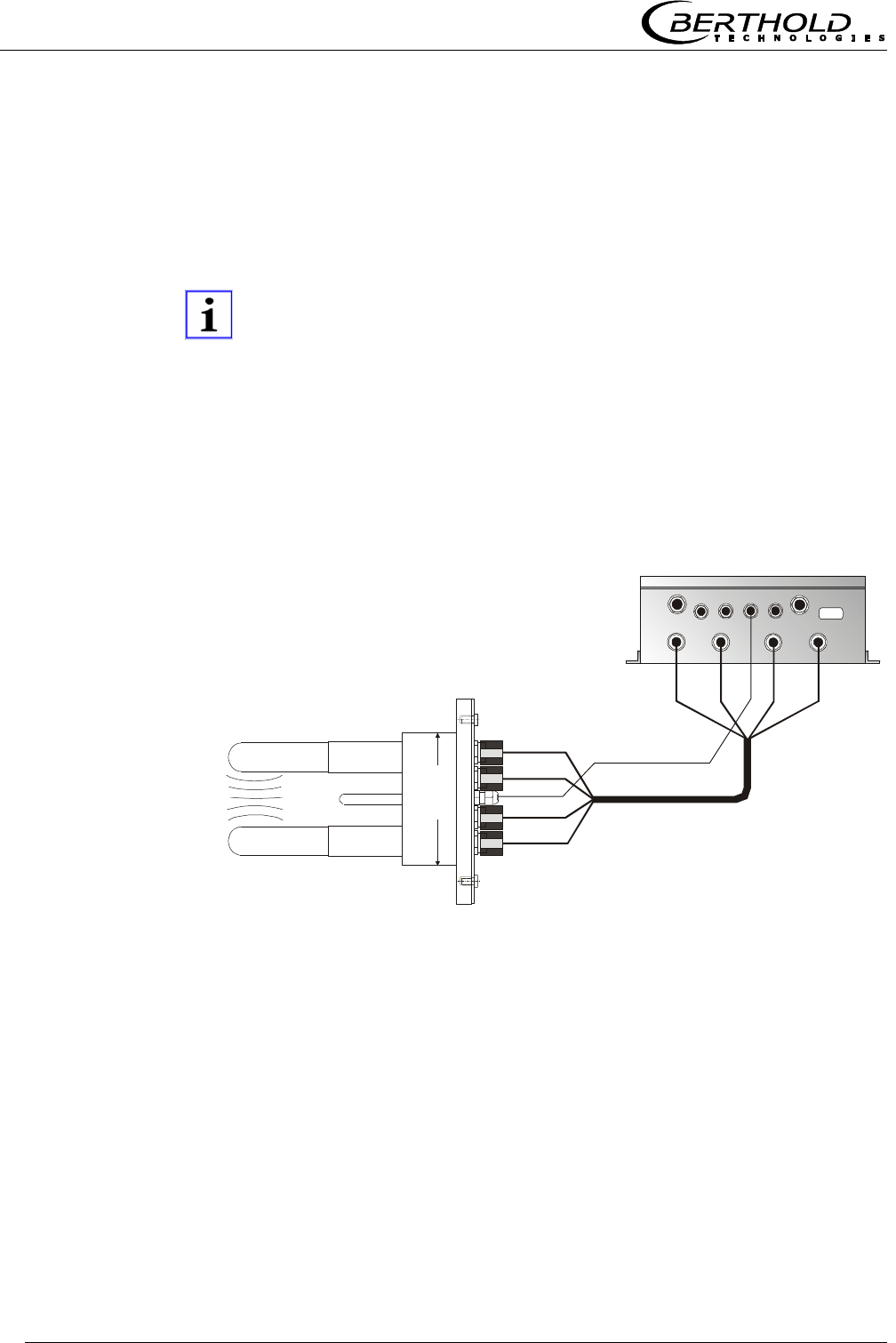
4.3.1 Connecting the HF Cable
You need a HF quad cable to connect the pan probe to the evalua-
tion unit.
Note!
Correct cable installation:
Make sure the cable does not get into contact with hot pipes over
the entire length (corrugated tube and single cable section after
splitting), e.g. direct contact with the device wall (not insulated).
This alone guarantees that all single cables are subject to the
same ambient conditions and that the compensation of the cable
drift works properly.
Figure 14:
Connection
of the dis-
continuous
probe on the
evaluation
unit
The HF cables and the HF connections on the evaluation unit and
on the probe are labeled. Connect the probe to the evaluation unit
as shown in Figure 14.

Chapter 4 Getting Started
Micro-Polar Brix LB 565 31
Note!
When tightening the 21 mm screw nut, make sure that the con-
nector is not twisted on the cable. If the connector is twisted rela-
tive to the cable, the shielding may get damaged and this could
result in mismatching and bad sealing.
Hand tighten all screwed connections of the HF cable (2 Nm = 0.2
kg/m)! Before tightening, carefully screw on the cable by hand.
Caution! Threaded joint jams easily.
Occasionally you should check if the screwed connection is still
properly tightened. If the installation is exposed to vibrations, the
screwed connection may come loose and this may result in inaccu-
rate measurements or corrosion of the connections.
As long as the cables are not connected, the coaxial sockets have
to be covered immediately with plastic caps and the cable connec-
tors have to be protected by suitable provisions against moisture
and dirt.
Note!
Never bend HF cables! The bending radius should not be less than
100 mm. After installation, fix cables with cable binders or other
suitable means, so that the cable cannot slip any more!
Chapter 4 Getting Started
Micro-Polar Brix LB 565
32
4.3.2 Pin Configuration of the Connector Strip
Danger!
Electrical hazards:
Turn off power supply to ensure that contact with voltage-carrying
parts is avoided during installation and when servicing.
Turn off power supply before opening the instrument. Work on
open and live instruments is prohibited.
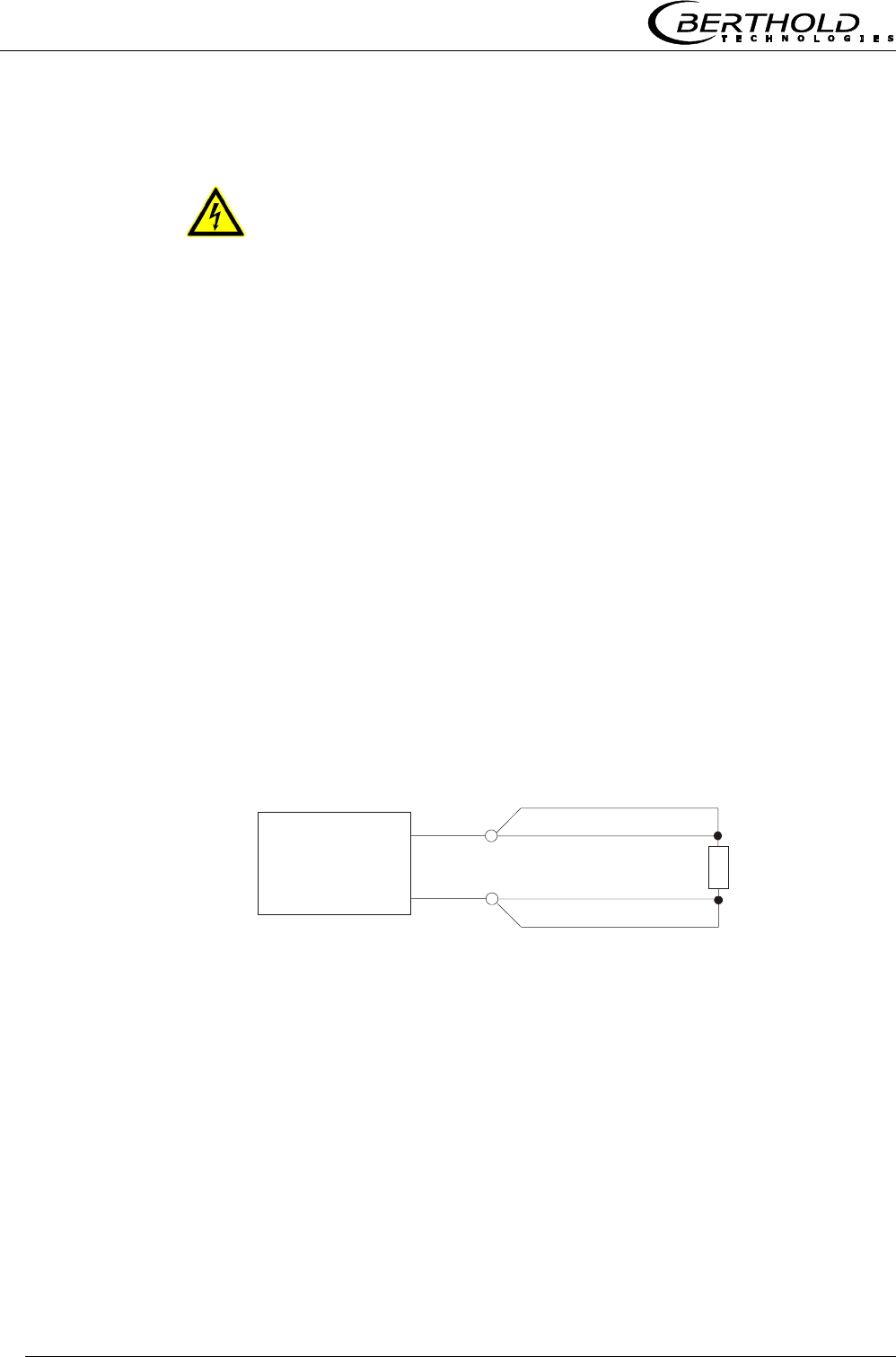
Temperature Signal Connection
A PT100 or a temperature current signal has to be connected to
current input 1 or 2 if significant temperature fluctuations occur in
the product and if a temperature dependence of the phase or at-
tenuation measurement is likely to occur. The temperature sensor
has to measure the material temperature in the vicinity of the mi-
crowave probe.
When taking the batch pan probe into operation, connect the 4-
wire cable of the PT-100 to the connector strip of the evaluation
unit as follows:
Figure 15:
PT-100 Connection
batch pan probe
Evaluation unit
Connector strip
( ) Terminal no.
(23)
blue
white
white
blue
PT-100 sensor
in the
batch pan probe
(11)

Chapter 4 Getting Started
Micro-Polar Brix LB 565 33
Other Connections
Connect all desired input and output signals to the terminal
strip as shown on the following pages. Use the M feed-through
to keep the degree of protection.
Check if the voltage indicated on the type plate matches your
local supply voltage.
Connect the line cable to the terminals 3(L1), 2(N) and 1(PE).
Check if the test switch (mains interruption) is in position „on“
(see Figure 17).
Close the instrument housing and turn on the power supply.
The line cross-section for power supply must be at least 1.0 mm2.
Chapter 4 Getting Started
Micro-Polar Brix LB 565
34
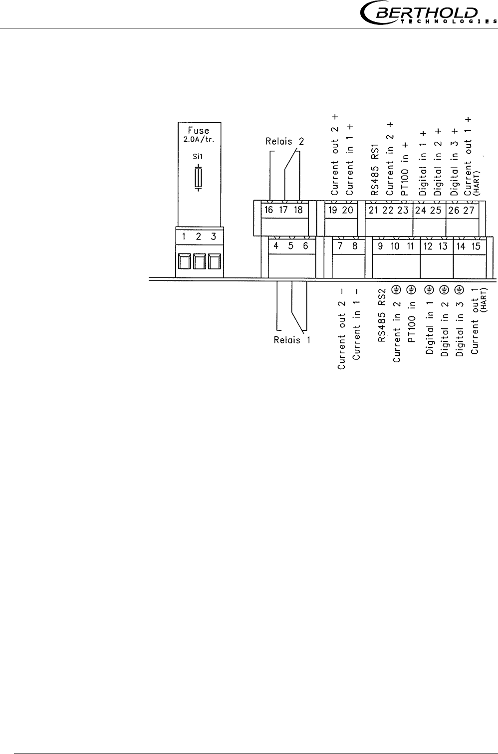
On the connector strip of the evaluation unit you find the following
connections:
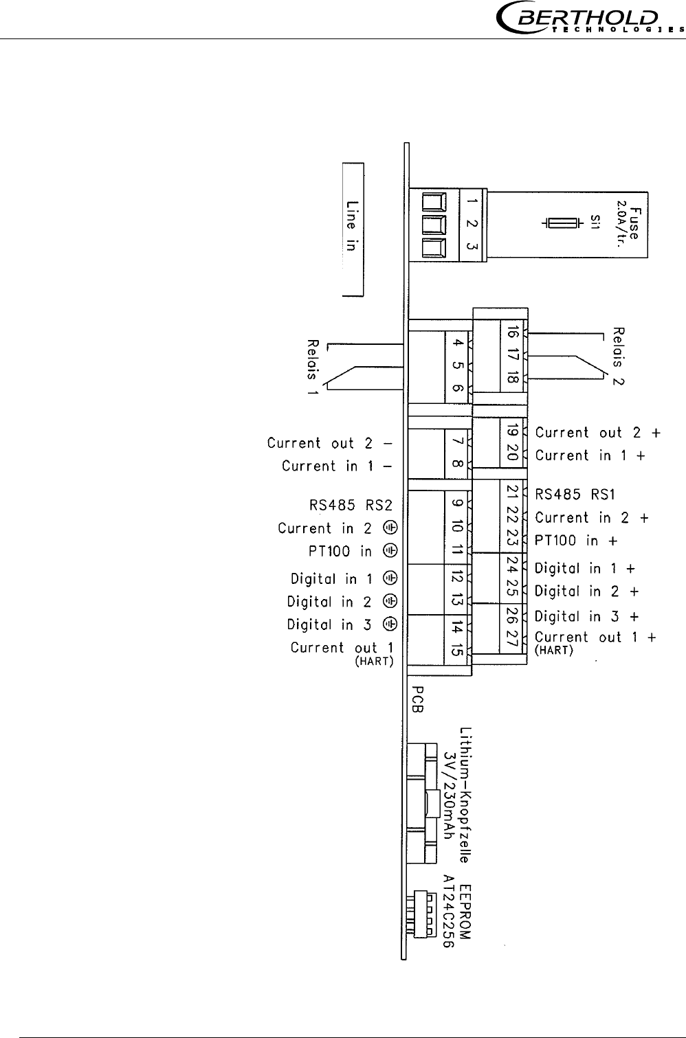
Figure 16:
Wiring diagram
LB 565
Power supply: Terminals 3 (L1), 2 (N) and 1 (PE)
90 V - 260 V AC, 45 - 65 Hz or
24 V AC/DC, DC: 18 V … 36 V ; AC: 24 V +5%, -20%; 45…65 Hz
Depending on the type of system, see type plate on the outer wall
of the housing.
Current input no. 1 (terminals 20+ and 8-), insulated
Input as 0/4 - 20 mA signal. For example, for temperature com-
pensation or reference signal recording.
Current input no. 2 (terminals 22+ and 10-), not insulated
Input as 0/4 - 20 mA signal. For example, for temperature com-
pensation or reference signal recording.
Current output no. 1 (terminals 27+ and 15-), insulated
Output as 4 - 20 mA signal. Output options: concentrations (1 /
2), current inputs signals (1 / 2) and PT100 signal
PE N L1

Chapter 4 Getting Started
Micro-Polar Brix LB 565 35
Current output no. 2 (terminals 19+ and 7-), insulated
Output as 0/4 - 20 mA signal. Output options: concentrations 1
and 2, current input signals 1 and 2 and PT100 signal
PT100 (terminals 23+ and 11-)
Connection for temperature measurement.
Digital input 1: DI1 (terminals 24+ and 12-)
Configuration options:
no function
measurement: start (closed) and stop (open)
Digital input 2: DI2 (terminals 25+ and 13-)
Configuration options:
no function
average value: hold (closed) and continue averaging (open)
product selection: product 1 (open) and product 2 (closed)
Digital input 3: DI3 (terminals 26+ and 14-)
Configuration options:
no function
start sampling, open: no action, closed: unique measurement
starts
product selection
Relay 1: (terminals 4, 5 and 6)
Changeover contacts, insulated, configuration option:
no function
error message
measurement stopped
limit value min. and max.
no product

Chapter 4 Getting Started
Micro-Polar Brix LB 565
36
Relay 2: (terminals 16, 17 and 18)
Changeover contacts, insulated, configuration option:
no function
error message
measurement stopped
limit value min. and max.
no product
RS485 interface (terminals 21 (RS1) and 9 (RS2))
Transfer rate 38400 baud, 8 data bits, 1 stop bit, no parity, no
handshake. Bidirectional, serial data interface for communication
and protocol output
RS232 interface (on instrument underside)
9-pole D-connectors. Data transfer rate 38400 baud, 8 data bits, 1
stop bit, no parity, no handshake. Bidirectional, serial data inter-
face for communication and protocol output.
Chapter 4 Getting Started
Micro-Polar Brix LB 565 37
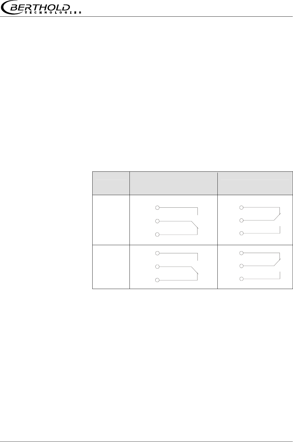
4.3.3 Digital Outputs, Relays
The status of the measurement is output via two relays:
Error
Alarm (alarm min. and max.)
No product
Under menu item Plausibility, you may enter a min. attenuation
for pause detection (e.g. for discontinuous evaporation crystal-
lizer); if this value is not reached, „no product“ is signalled via
a relay and the current output drops to 0 or 4 mA.
Measurement stopped
The respective switching status is also signaled via LED’s on the
front panel (LED’s: signal 1 and 2).
Relay no. Error, alarm, no product,
measurement stopped,
current-free status
Normal
1
2
The relays with changeover contacts can either be operated as
make contact, terminals 4 & 5 (open at error, alarm ...) or as
break contact, terminals 5 & 6 (closed at error, alarm ...).
com
4
5
6
com
16
17
18
com
4
6
5
com
16
18
17

Chapter 5 Service Instructions
Micro-Polar Brix LB 565
38
Chapter 5. Service Instructions
5.1 General Information
The evaluation unit has no wearing parts or components requiring
any special maintenance.
A malfunction of the measuring system is not always due to a de-
fect in the instrument. Often the error is caused by incorrect op-
eration, wrong installation, or irregularities in the product being
measured.
If a malfunction occurs, anyway, the measuring system helps you
to identify and eliminate errors by displaying error messages on
the LCD, indicating operator errors and defects of the electronics.
Moreover, the modular design of the measuring system simplifies
the replacement of individual module components.
Usually, faulty modules of the evaluation unit cannot be repaired
but have to be replaced. The microwave module is fixed with
screws to a shielding cover and must not be opened.
5.2 Instrument Cleaning
Clean all system components using only a moistened cloth without
chemical cleaning agent. Parts coming into contact with the prod-
uct (during regular operation) can be cleaned with hot water, tak-
ing into account the temperature limits (see chapter 6.2).
5.3 Batteries
If the measuring system LB 565 is without power supply (power
failure or disconnected from mains), the system clock is supplied
with power via the Lithium battery on the CPU. The instrument
works correctly even with empty battery, only measured data
which are output via one of the serial interfaces may become use-
less as a result of the faulty date and time information.
The service life of the battery, even under continuous load, is at
least 8 years. To replace the battery, you have to disconnect the
instrument from mains. Battery data see chapter 8.2 Electrical
Wiring Diagram.
Battery type: 3 Volt Lithium cell (button cell), type CR2032.
Chapter 5 Service Instructions
Micro-Polar Brix LB 565 39
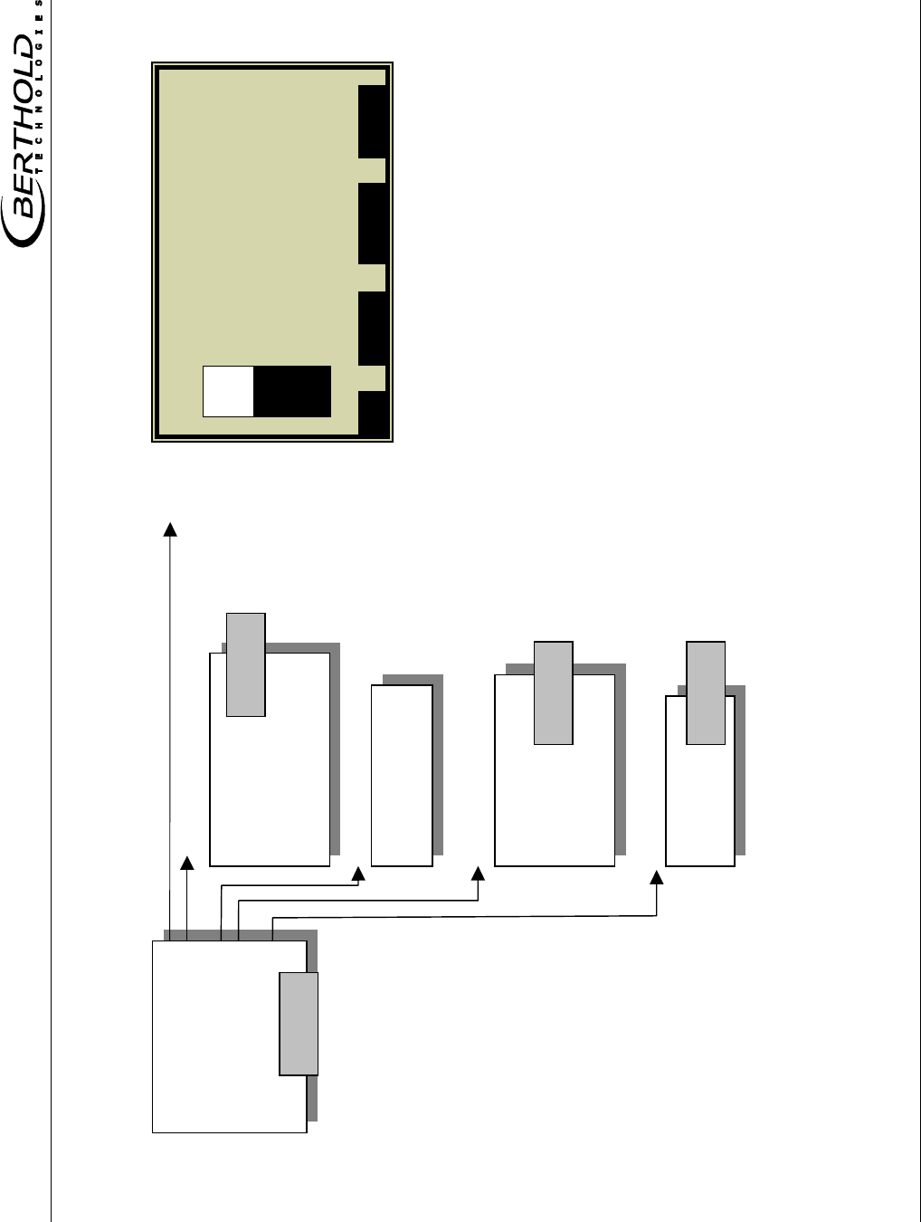
0
I
Netzteil
Fuse
Line connector
Terminal strip
(can be pulled off)
Battery
EEprom
(can be pulled off)
Feed-through for
line connector
Test switch Motherboard
Protective cover
5.4 Fuse Replacement
The mains fuse of the LB 565 is located in the wall housing. Re-
place the fuse only if the instrument is disconnected from mains.
Be sure that the new fuse matches the rating specified.
Use only fuse with correct rating:
Instrument version with 90 V ... 260 V AC: 2.0 A slow-blow
Instrument version with 24 V AC/DC: 2.0 A slow-blow
Warning!
Spare fuses must match the rating specified by the device manu-
facturer. Short-circuiting or manipulation is not permitted.
Figure 17:
View with
open wall
housing
Chapter 6 Technical Data
Micro-Polar Brix LB 565
40
Chapter 6. Technical Data
General Specifications
Method Microwave transmission measurement
Working
frequency
2.4 – 2.5 GHz (ISM band), depending on local
regulations
Transmission
power
< 0.1 mW (< - 10 dBm), coaxial line power
Applications
Concentration measurement in sugar solutions
in containers and pipes
6.1 Evaluation Unit
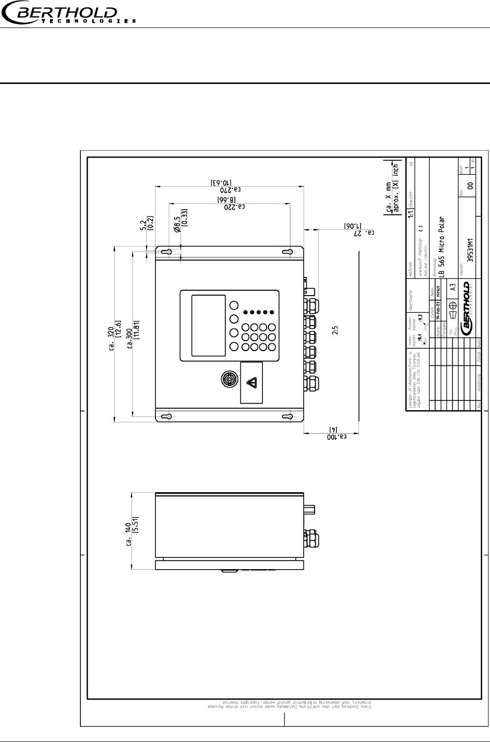
Evaluation Unit
Housing Wall housing made of stainless steel, material
1.4571 (~316+Ti), HxWxD: 300 x 323 x 140
mm, see dimensional drawing in chapter 8
Protection type IP 65
Weight approx. 6.5 kg
Operating
temperature
0 °C ... + 60 °C ( 273 K ...333 K ),
no condensation
Storage
temperature
- 20 °C ... + 80 °C ( 253 K ... 353 K ),
no condensation
Display Dot matrix LC display, 114 mm x 64 mm, 240
x 128 pixels, with back-lighting, automatic con-
trast setting
Keyboard Freely accessible foil keypad, light-stable and
weatherproof: alphanumeric keyboard and 4
softkeys (software-assigned buttons)
Power supply Depending on instrument version:
1. 90 V - 260 V AC, 45 Hz – 65 Hz
2. 24 V AC/DC; DC: 18 V – 36 V; AC: 24 V
+5%, -20%, 45 Hz – 65Hz
Power
consumption max. 30 VA (AC/DC),
depending on configuration

Chapter 6 Technical Data
Micro-Polar Brix LB 565 41
Fuses 2.0 A / slow-blow
Battery type 3 V Lithium button cell, type CR2032
Measured value Concentration, dry mass content, Brix
Communication
module
Preparation for HART
Inputs and Outputs
Cable
cross-section
min. 1.0 mm² (mains supply)
Cable
feed-through
2 x M20x1.5 for cable 5...14mm
(depending on application),
4 x M16x1.5 for cable 5 ...8 mm
(depending on application)
Probe connection Inputs and outputs for signal and
reference channel, 50 Ω N-socket
Probes Cable lengths: 2 m, 6 m and 10 m; 50 Ω ;
both sides with 4 N connectors
Current input 2 x current input 0/4 ...20 mA, ohmic resis-
tance 50 Ω, 1x insulated, 1x instrument ground
e.g. for temperature compensation
Current output Current output 1: 4...20 mA, ohmic resistance
max. 800 Ω , insulated
current output 2: 0/4...20 mA, ohmic resis-
tance max. 800 Ω , insulated
e.g. for measured value or temperature output
PT-100
connection
Measuring range: - 50 °C ... + 200 °C (223 K
... 473 K); measurement tolerance: < 0,4 °C
Digital input 3 x digital inputs (DI1..3), for floating contacts,
TTL-level connected to instrument ground
Configuration options:
DI1: none, measurement start/stop
DI2: none, measurement hold, product
DI3: none, sample measurement, product
Function description:
1. Measurement (Start/Stop), open: meas-
urement stopped, closed: measurement
started or measurement running
2. Hold measurement, open: measurement
running, closed: measurement stopped, i.e.
average values and current output are held

Chapter 6 Technical Data
Micro-Polar Brix LB 565
42
3. Product selection, open: product 1 (P1),
closed: P2; with two DI’s: DI2 open & DI3
open: P1, DI2 closed & DI3 open: P2, DI2
open & DI3 closed: P3, DI2 closed &DI3
closed: P4
4. Start sample measurement, open: no ac-
tions, closed: single measurement starts
Relay outputs 2 x relay (SPDT), insulated
Configuration options:
- collective error message
- measurement hold
- threshold (min. and max.)
- no product
Loading capacity:
AC: max. 400VA
DC: max. 90W
AC / DC: max. 250V or max. 2A, not
inductive
≥ 150V: voltage must be grounded
Restrictions for 24 V AC/DC (DC: 18 V...36 V;
AC: 24 V +5 %, -20 %) mains supply, if the
ground conductor is not connected to terminal
1 (PE):
AC: max. 50 V
DC: max. 70 V
Serial interface
(bidirectional)
RS 232 on the underside of the instrument,
38400 baud, no handshake, data format 8 data
bits, 1 stop bit
RS 485 via terminal block, 38400 baud, no
handshake, data format 8 data bits, 1 stop bit

Chapter 6 Technical Data
Micro-Polar Brix LB 565 43
6.2 Probes
Pan Probes
Application Pan probes with and without rinsing device
for concentration measurement in process
containers and in pipelines with nominal
width ≥ 200 mm.
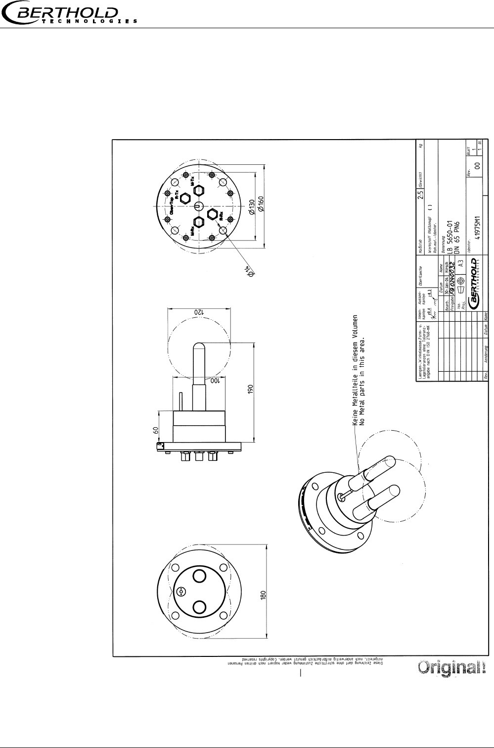
Material Plastic rod, stainless steel 1.4301
Process coupling Flange according to DIN 2527 DN65 / PN6,
DN 80, 100, 150 / PN16; ANSI Flange 2.5’’ /
150 PSI (others on request)
Process pressure 0 ... + 3 bar (relative)
Temperature range Product temperature: + 10 °C ...+100 °C,
short-term up to + 120 °C; storage tem-
perature: + 10 °C to + 80 °C
Connections 4 x HF cable: 50 Ω , N-connectors on both
sides (max. 10 m HF cable)
Dimensions See dimensional drawings in chapter 8
Chapter 7 Certificate
Micro-Polar Brix LB 565
44
Chapter 7. Certificate
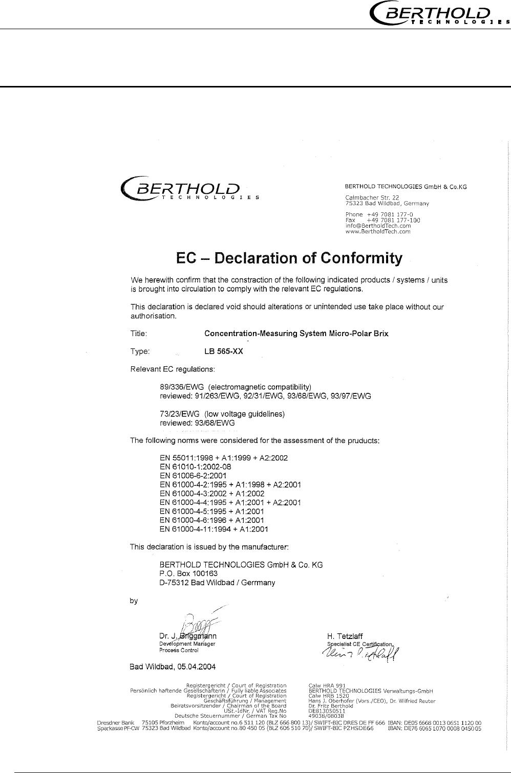
7.1 EC-Declaration of Conformity
Chapter 7 Certificate
Micro-Polar Brix LB 565 45
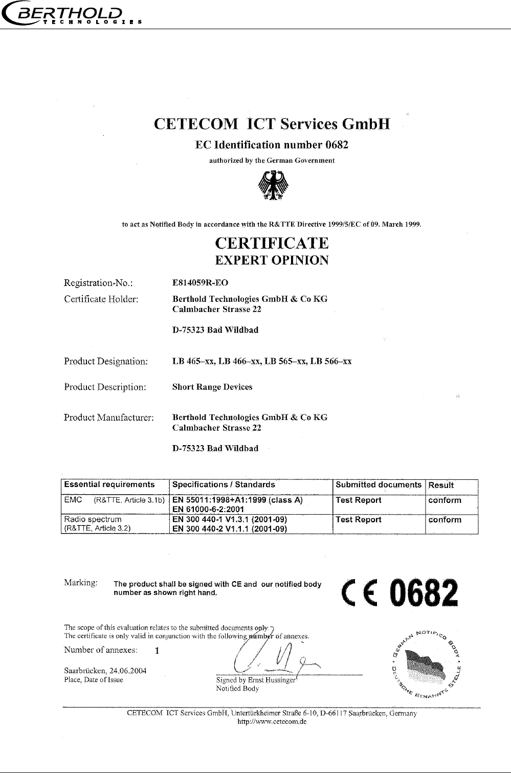
7.2 Frequency approval
Chapter 7 Certificate
Micro-Polar Brix LB 565
46
Chapter 8 Engineering drawings
Micro-Polar Brix LB 565 47
Chapter 8. Engineering drawings
8.1 Dimensional drawing for housing
Chapter 8 Engineering drawings
Micro-Polar Brix LB 565
48
8.2 Electrical Wiring Diagram
PE N L1
Chapter 8 Engineering drawings
Micro-Polar Brix LB 565 49
8.3 Dimensional drawings for batch pan probes
8.3.1 Type LB 5650-01
Chapter 8 Engineering drawings
Micro-Polar Brix LB 565
50
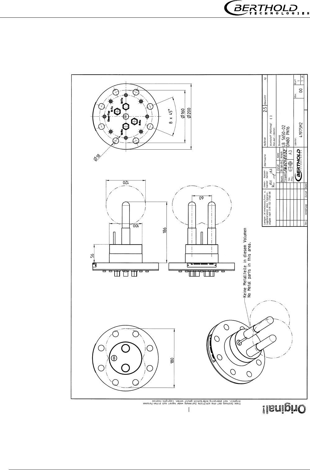
8.3.2 Type LB 5650-02
Chapter 8 Engineering drawings
Micro-Polar Brix LB 565 51
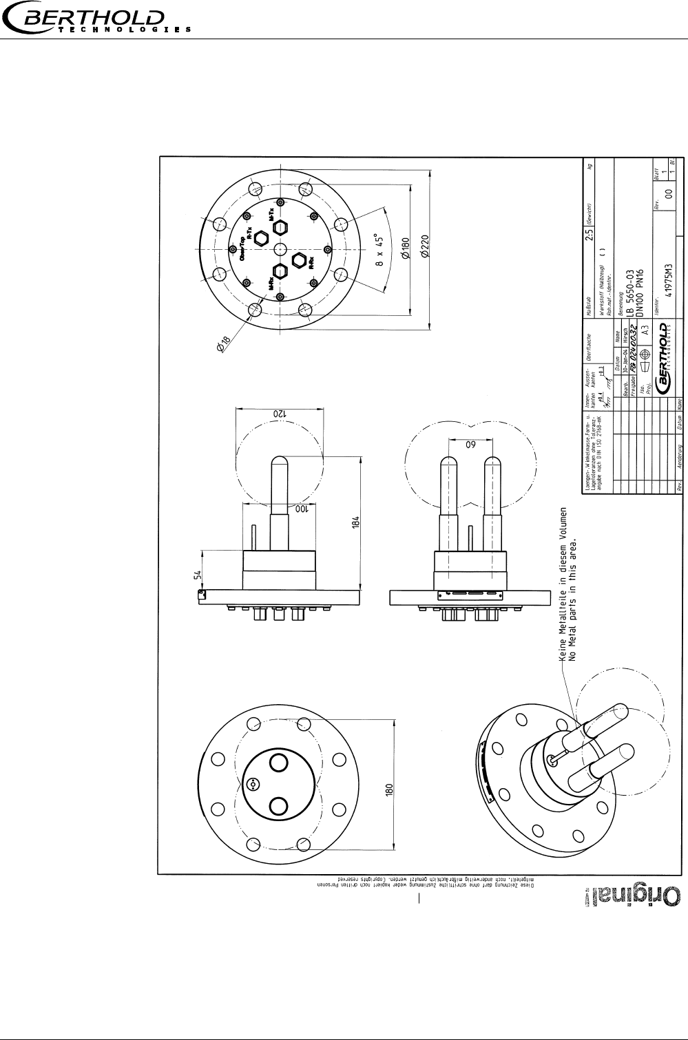
8.3.3 Type LB 5650-03
Chapter 8 Engineering drawings
Micro-Polar Brix LB 565
52
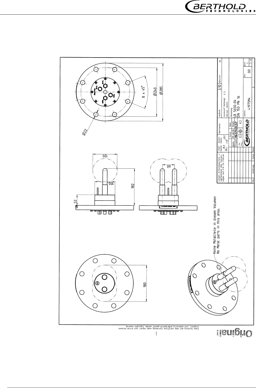
8.3.4 Type LB 5650-04
Chapter 8 Engineering drawings
Micro-Polar Brix LB 565 53
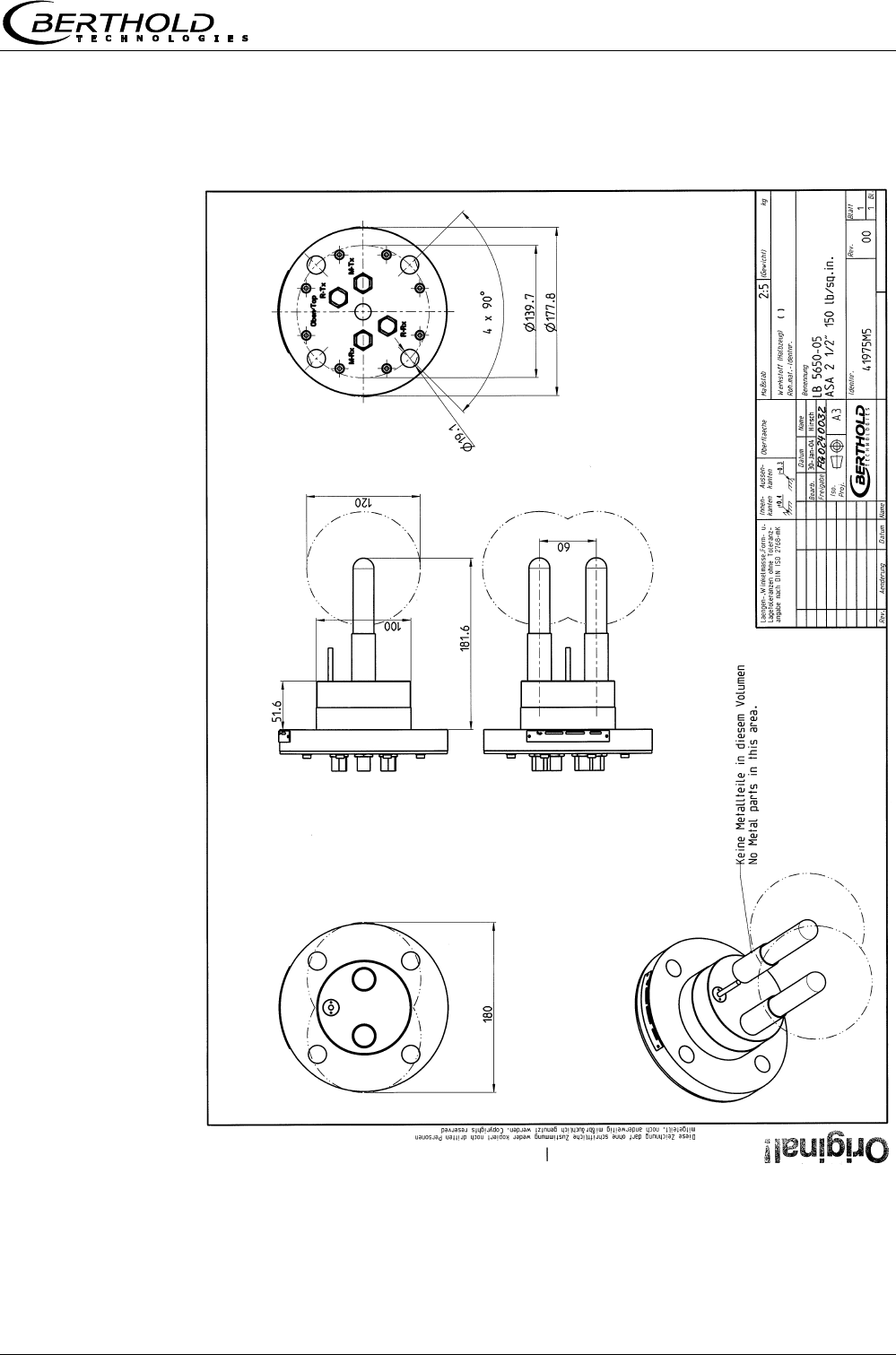
8.3.5 Type LB 5650-05
Chapter 8 Engineering drawings
Micro-Polar Brix LB 565
54
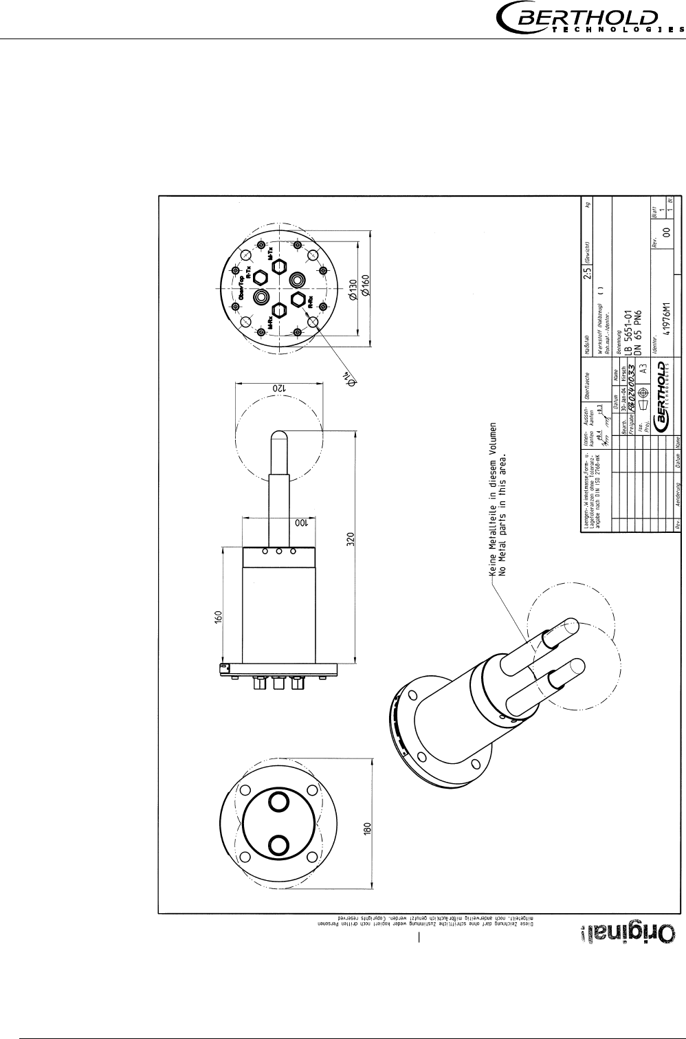
8.4 Dimensional drawings for continuous pan probes
8.4.1 Type LB 5651-01
Chapter 8 Engineering drawings
Micro-Polar Brix LB 565 55
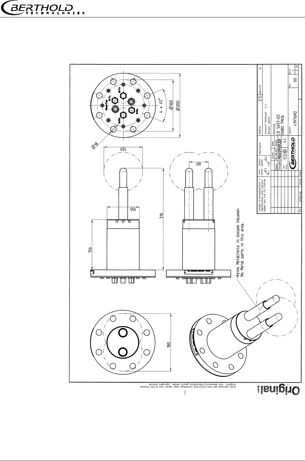
8.4.2 Type LB 5651-02
Chapter 8 Engineering drawings
Micro-Polar Brix LB 565
56
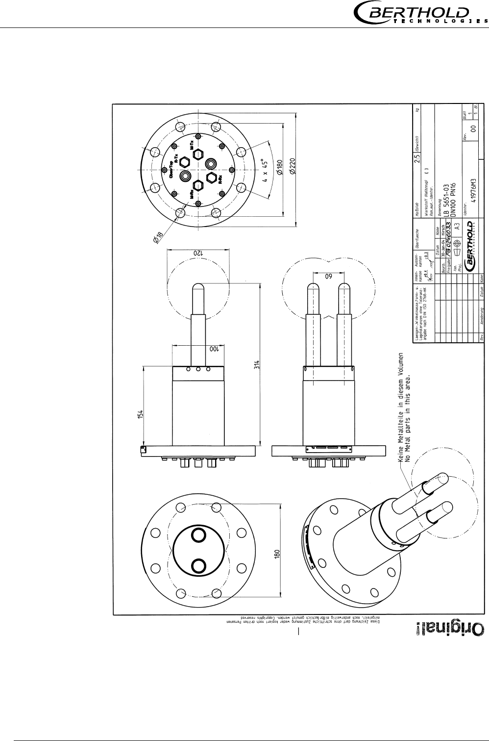
8.4.3 Type LB 5651-03
Chapter 8 Engineering drawings
Micro-Polar Brix LB 565 57
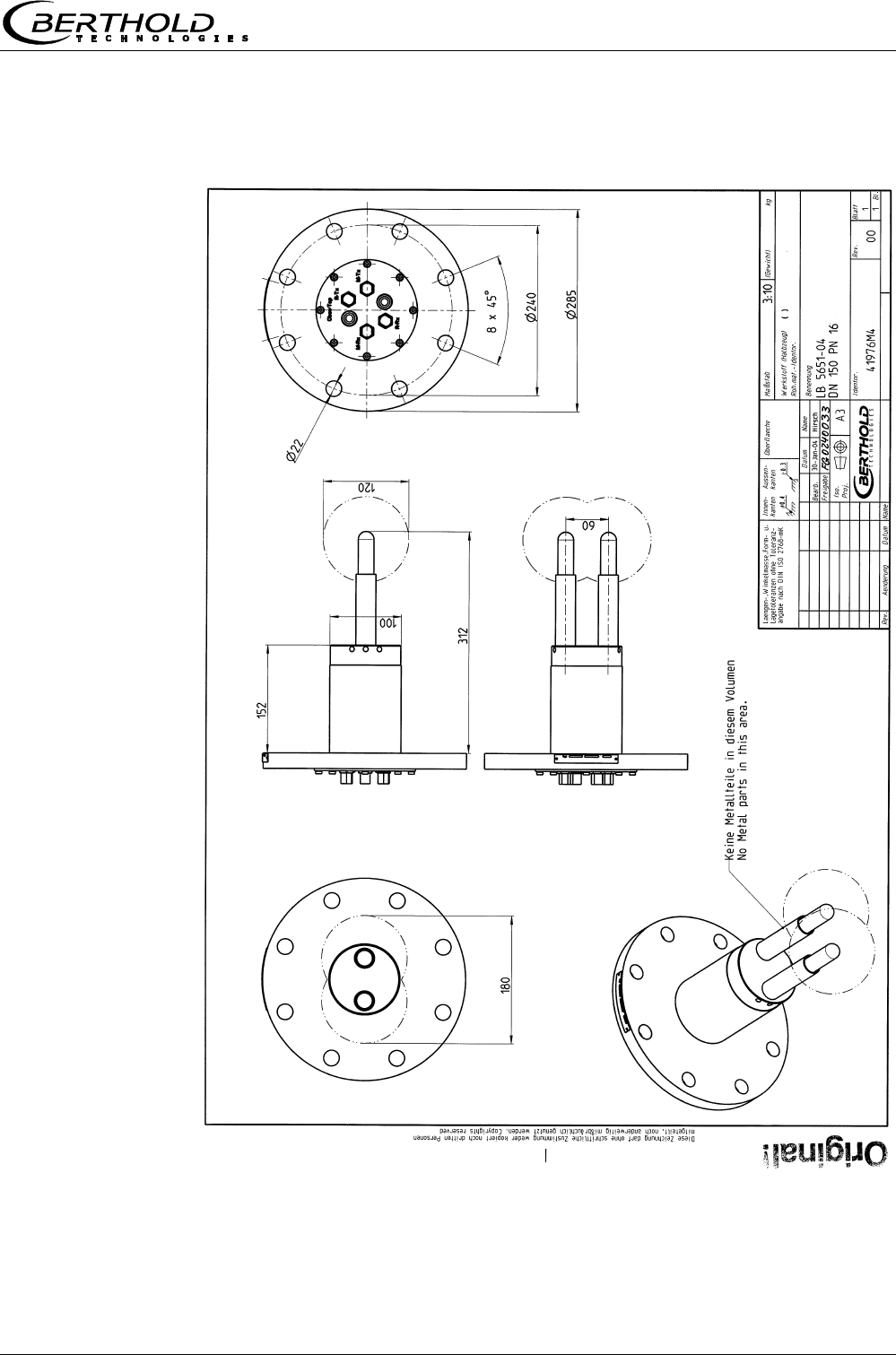
8.4.4 Type LB 5651-04
Chapter 8 Engineering drawings
Micro-Polar Brix LB 565
58
8.4.5 Type LB 5651-05
Chapter 8 Engineering drawings
Micro-Polar Brix LB 565 59
8.5 Installation sheets for LB 5650 (Batch pan probes)
ø
14
M-Rx
R-Tx
do not remove, only
in case of service by
Berthold Technologies
R-Rx
M-Tx
ø
160
Oben/Top
ø
130
microwave
measuring field
current stream
probe flange DN65 / PN6
pan probe
evaluation unit
botten side
90 V - 260 V AC
or 24 V AC/DC
output
0/4 - 20 mA
Micro-Polar With Pan Probe
- Installation In Evaporation Crystallizer -
Bri
x
installation
position
top view into the
evaporation crystallizer
sealing
insulation
pan wall
ø
130 / 4 x M12
190
ø
100
ø
160
60
heating
area without
metalic
installations
fitting flange
BERTHOLD TECHNOLOGIES GmbH & Co. KG . P.O. Box 100 163 . D-75312 Bad Wildbad, Germany
Phone +49 7081 177-0 . Fax +49 7081 177-100 . industry@BertholdTech.com
www.BertholdTech.com
60
evaluation unit
220
300
Micro-Polar
Id.-No. 41975TI2 Rev.01
ø
±
102
0,5
PT100
PT100
PT100
M-Tx
M-Tx
M-Tx
M-Rx
M-Rx
R-Tx
R-Tx
R-Rx
R-Rx
M-Rx
R-Tx
R-Rx
HF cable quad
Chapter 8 Engineering drawings
Micro-Polar Brix LB 565
60
90 V - 260 V AC
or 24 V AC/DC
output
0/4 - 20 mA
sealing
Id.-No. 41975TI21 Rev.01
ø
A / 8 x S
190
ø
100
ø
B
60
60
220
300
Micro-Polar
probe flange DN80, 100, 150 / PN16
pan probe
installation
position
DN ABC
S
80
100
160 200 18 M16
180 220 18 M16
240 28522M20
150
ø
±
102
0,5
PT100
M-Tx
M-Tx
M-Tx
M-Rx
M-Rx
R-Tx
R-Tx
R-Rx
R-Rx
M-Rx
R-Tx
R-Rx
M-Rx
R-Tx
R-Rx
M-Tx
ø
C
Oben/Top
ø
B
ø
A
PT100
insulation
PT100
do not remove, only
in case of service by
Berthold Technologies
microwave
measuring field
pan wall
top view into the
evaporation crystallizer
Micro-Polar With Pan Probe
- Installation In Evaporation Crystallizer -
Bri
x
evaluation unit
botten side
HF cable quad
evaluation unit
heating
area without
metalic
installations
BERTHOLD TECHNOLOGIES GmbH & Co. KG . P.O. Box 100 163 . D-75312 Bad Wildbad, Germany
Phone +49 7081 177-0 . Fax +49 7081 177-100 . industry@BertholdTech.com
www.BertholdTech.com
current stream
fitting flange
Chapter 8 Engineering drawings
Micro-Polar Brix LB 565 61
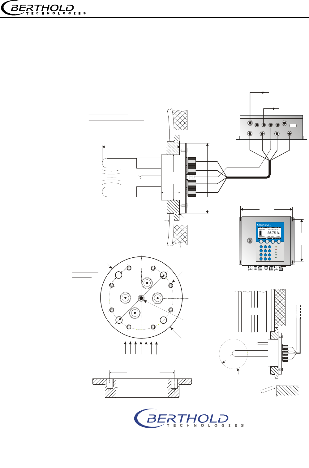
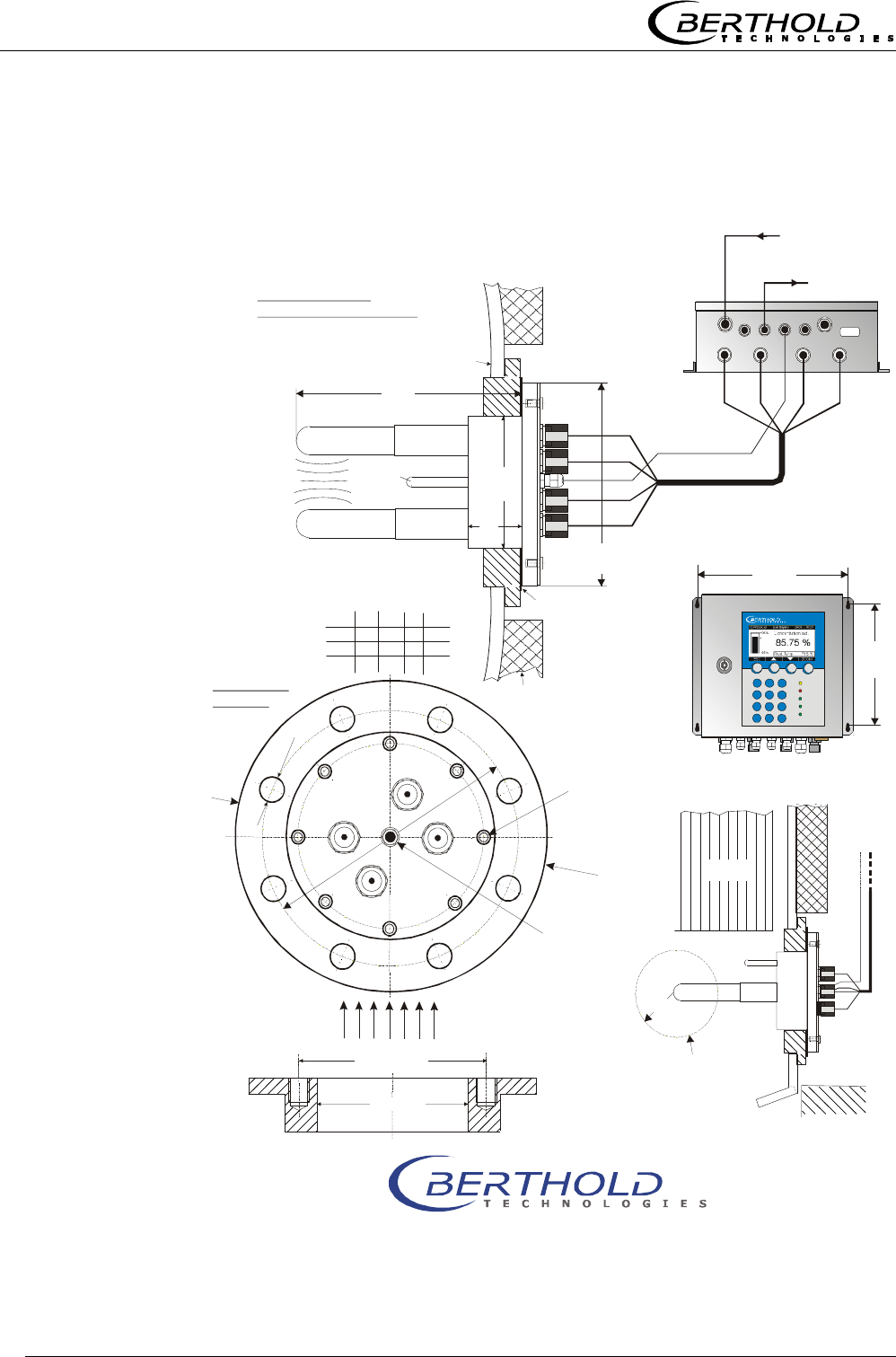
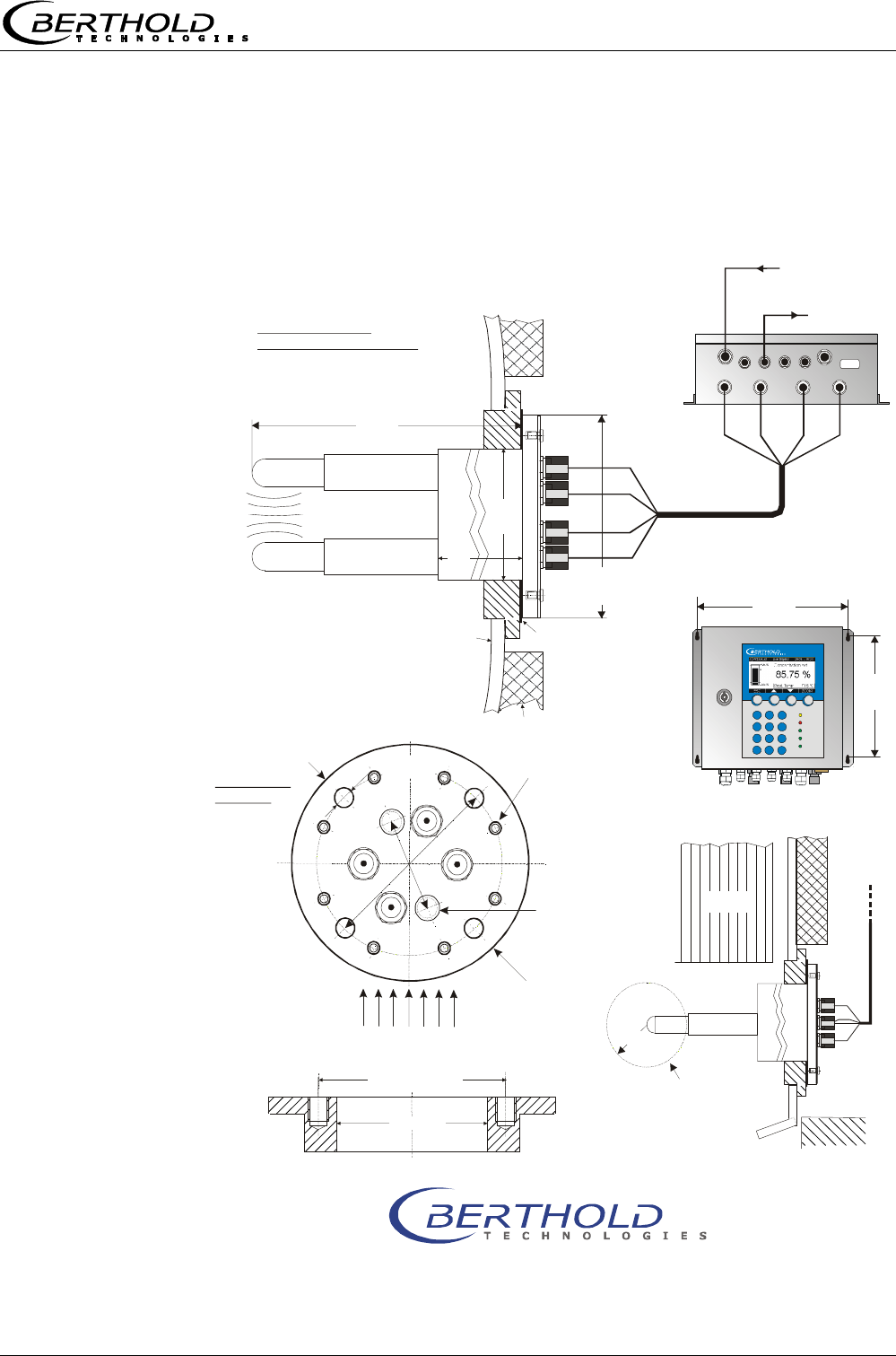
8.6 Installation sheets for LB 5651 (Continuous pan
probes)
ø
14
M-Rx
R-Tx
90 V - 260 V AC
or 24 V AC/DC
output
0/4 - 20 mA
installation
position
R-Rx
M-Tx
ø
160
ø
160
160
ø
130 / 4 x M12
ø
±
102
0,5
320
220
300
ø
100
Micro-Polar
60
Id.-No. 41976TI2 Rev.02
M-Tx
M-Tx
M-Tx
M-Rx
M-Rx
R-Tx
R-Tx
R-Rx
R-Rx
M-Rx
R-Tx
R-Rx
Oben/Top
ø
130
55
Micro-Polar With Continuous Pan Probe
- Installation In Evaporation Crystallizer -
Bri
x
BERTHOLD TECHNOLOGIES GmbH & Co. KG . P.O. Box 100 163 . D-75312 Bad Wildbad, Germany
Phone +49 7081 177-0 . Fax +49 7081 177-100 . industry@BertholdTech.com
www.BertholdTech.com
microwave
measuring field
top view into the
evaporation crystallizer
evaluation unit
botten side
HF cable quad
evaluation unit
sealing
insulation
do not remove, only
in case of service by
Berthold Technologies
heating
area without
metalic
installations
current stream
fitting flange
probe flange DN65 / PN6
cont. pan probe
2 x 3/8’’
flushing connection
(internal thread)
pan wall
Chapter 8 Engineering drawings
Micro-Polar Brix LB 565
62
M-Rx
R-Tx
R-Rx
M-Tx
55
90 V - 260 V AC
or 24 V AC/DC
output
0/4 - 20 mA
ø
B
160
ø
A / 8 x S
320
ø
100
60
ø
C
installation
position
Oben/Top
ø
B
ø
A
DN ABC
S
80
100
160 200 18 M16
180 220 18 M16
240 28522M20
150
220
300
Micro-Polar
Id.-No. 41976TI21 Rev.02
ø
±
102
0,5
2 x 3/8’’
flushing connection
(internal thread)
M-Tx
M-Tx
M-Tx
M-Rx
M-Rx
R-Tx
R-Tx
R-Rx
R-Rx
M-Rx
R-Tx
R-Rx
Micro-Polar With Continuous Pan Probe
- Installation In Evaporation Crystallizer -
Bri
x
BERTHOLD TECHNOLOGIES GmbH & Co. KG . P.O. Box 100 163 . D-75312 Bad Wildbad, Germany
Phone +49 7081 177-0 . Fax +49 7081 177-100 . industry@BertholdTech.com
www.BertholdTech.com
top view into the
evaporation crystallizer
pan wall
microwave
measuring field
evaluation unit
botten side
HF cable quad
evaluation unit
sealing
insulation
do not remove, only
in case of service by
Berthold Technologies
heating
area without
metalic
installations
current stream
fitting flange
probe flange DN80, 100, 150 / PN16
cont. pan probe

Micro-Polar Brix LB 565 63
Notes

Micro-Polar Brix LB 565
64
Notes

Micro-Polar Brix LB 565

Micro-Polar Brix LB 565
detect and identify
Process Control
Concentration Meter
Micro-Polar Brix LB 565
Software Manual
ID No. 39531BA2
Rev. No.: 00 01/07/04
Soft. Version 1.00
User’s Guide

Micro-Polar Brix LB 565
The units supplied should not be repaired by anyone other than Berthold Service
engineers or technicians authorized by Berthold.
In case of operation trouble, please address to our central service department.
The complete user’s guide consists of two manuals, the hardware description and the software
description.
The hardware manual comprises:
mechanical components
assembly
electrical installation
radiation protection guidelines
technical data
electrical and mechanical drawings
The software manual comprises:
operation of the evaluation unit
parameter description
basic setting
calibration
error messages
The present manual is the software description.
Subject to change without prior notice.

Table of Contents
Micro-Polar Brix LB 565
Table of Contents
Page
Chapter 1. Communication with Micro-Polar Brix......................7
1.1 Brief Instructions........................................................8
1.2 System Configuration..................................................8
1.3 System Calibration .....................................................8
Chapter 2. Software Functions ..................................................9
2.1 Information on Menu Structure ....................................9
2.2 Menu Structure ........................................................10
2.2.1 Start Menu...............................................................12
2.2.2 Diagnostic................................................................12
2.2.3 Setup ......................................................................13
2.2.4 Access Level.............................................................13
2.2.5 Language.................................................................14
2.2.6 Configuration ...........................................................14
2.2.7 General ...................................................................14
2.2.8 Measurement ...........................................................15
2.2.9 Plausibility ...............................................................15
2.2.10 Microwave..............................................................16
2.2.11 Calibration .............................................................16
2.2.12 System Adjust ........................................................16
2.2.13 Calibrate Concentration ...........................................17
2.2.14 Sample No. ............................................................17
2.2.15 Sample Data (expanded) .........................................18
2.2.16 Advanced Settings ..................................................18
2.2.17 Calibr. manual ........................................................19
2.2.18 Input / Output ........................................................19
2.2.19 Current Output .......................................................20
2.2.20 Current Out 1 .........................................................20
2.2.21 Current Out 2 .........................................................21
2.2.22 Current Input .........................................................21
2.2.23 Current In 1 ...........................................................21
2.2.24 Current In 2 ...........................................................21
2.2.25 Pt 100 ...................................................................22
2.2.26 Digital Output.........................................................22
2.2.27 Digital Input ...........................................................23
Chapter 3. Configuration.........................................................24
3.1 Configuration Setup .................................................. 24
3.1.1 General Data............................................................24
3.1.2 Measurement ...........................................................25
3.1.3 Plausibility ...............................................................26
3.1.4 Microwave ...............................................................26
Chapter 4. Calibration .............................................................27
4.1 System Calibration ................................................... 27
4.2 Start Calibration ....................................................... 29
4.2.1 Tuning.....................................................................29
4.2.2 Sampling .................................................................32

Table of Contents
Micro-Polar Brix LB 565
4.2.3 Entering the Laboratory Values...................................33
4.2.4 Automatic Calibration ................................................35
4.3 Manual Calibration.................................................... 36
4.3.1 Manual Calibration with One Concentration ..................36
4.3.2 Calibration with Two Concentrations............................39
4.3.3 Calibration with Split Value ........................................43
4.3.4 Calibration with Temperature Compensation.................45
Chapter 5. Password .............................................................. 48
5.1 Password................................................................. 48
Chapter 6. Inputs / Outputs ................................................... 49
6.1 Current Outputs ....................................................... 49
6.1.1 Current Output Setup ................................................50
6.1.2 Test and Adjustment .................................................51
6.1.3 Error Current ............................................................53
6.1.4 Current Output 2 ......................................................54
6.2 Current Inputs ......................................................... 55
6.2.1 Enabling the Current Input.........................................55
6.2.2 Range Setting and Adjustment ...................................56
6.3 Pt 100..................................................................... 58
6.3.1 Pt 100 Enabling ........................................................58
6.3.2 Pt 100 Calibration .....................................................59
6.4 Digital Output .......................................................... 60
6.4.1 Digital Output Assignment .........................................60
6.5 Digital Input ............................................................ 61
6.5.1 External Product Switchover.......................................62
Chapter 7. Factory Settings .................................................... 63
Chapter 8. Error Lists ............................................................. 64
8.1 Error Lists ............................................................... 64
8.1.1 Hardware Error.........................................................64
8.1.2 Input Error...............................................................64
8.1.3 Measurement Error ...................................................65
Chapter 9. Calibration Data Sheet .......................................... 66
9.1 Configuration ........................................................... 66
9.1.1 General ...................................................................66
9.1.2 Measurement ...........................................................66
9.1.3 Plausibility ...............................................................66
9.1.4 Microwave................................................................66
9.2 Product ................................................................... 67
9.3 Input / Output ......................................................... 67
9.3.1 Current Output .........................................................67
9.3.2 Current Input ...........................................................67
9.3.3 Pt 100 Input.............................................................68
9.3.4 Digital Output...........................................................68
9.3.5 Digital Input.............................................................68
9.4 Calibration Data ....................................................... 68
9.4.1 Calibration Coefficients ..............................................68
9.4.2 Sampling Table.........................................................69

Micro-Polar Brix LB 565
Safety Summary
GENERAL WARNINGS
Parameter settings
Never change the parameter settings without a full knowledge
of these operating instructions, as well as a full knowledge of the
behavior of the connected controller and the possible influence
on the operating process to be controlled.
Chapter 1. Communication with Micro-Polar Brix
Micro-Polar Brix LB 565 7
Chapter 1. Communication with Micro-Polar Brix
Communication with the Micro-Polar Brix takes place via
4 softkey buttons. The function of the individual buttons
changes relative to the position in the menu. Values and
texts are entered via an alphanumeric keyboard. The instru-
ment status is indicated by 5 LED’s.
and cable feed-through
Lock
Numerical
keypad
Softkey buttons
LED’s
LCD display
RS232 connection
HF connections for
signal cable reference cable
Micro-Polar

Chapter 1. Communication with Micro-Polar Brix
8 Micro-Polar Brix LB 565
1.1 Brief Instructions
The main menu is displayed automatically after power on, provided the Micro-Polar Brix has
been connected properly.
To get correct measurement values, the instrument has to be configured and calibrated before
running the first measurement.
1.2 System Configuration
Select | Setup | Configuration | General Data
Enter the general data (date, time, tag)
□< Push Home button to return to the Configuration menu and select | Measurement |
Enter the system parameters (measurement mode, start mode, averaging, units, ...)
□< Push Home button to return to the Configuration menu
Select | Plausibility |
Enter the limit values (limits conc. 1, variance of phase measurement, pause detection )
□< Push Home button to return to the Configuration menu
Select | Microwave |
Enter the cable length (reference cable length, signal cable length )
□< Push Home button to return to the Setup menu
Select | Input/Output |
Enter the values for current output, current input, Pt100, digital out-/input
□< Push Home button to return to the Setup menu.
1.3 System Calibration
You have to power on the instrument at least 30 minutes prior to system calibration.
On the main menu, select | Setup |Calibration | System Adjust | Adjust |
Start the adjustment only if it is sure that the transducer is sufficiently covered by the product.
The typical standard coefficients have been set up by the manufacturer for your application. A
sample has to be taken during system adjustment. The lab value of the sample is needed for
calculation of the offset. Calculation: analysis value – reading = offset. The offset can only be
entered in the Profi mode.
Upon completion of the system adjustment, push the □< Home button three times to return to
the main menu.
Push the „RUN“ softkey to start the measurement. The live display appears.
Push the „ESC“ button to return to the main menu and select | Setup | Calibration | Calibrate
Conc. | Tuning | Offset |
Enter offset value.
Push the □< Home button 4 times to return to the main menu.
Select | Live display |
If the product has not changed, the reading value corresponds to the laboratory value.

Chapter 2. Software Functions
Micro-Polar Brix LB 565 9
Chapter 2. Software Functions
2.1 Information on Menu Structure
The menu structure on the following pages provides an over-
view of all functions of the Micro-Polar Brix. Using the page
numbers indicated you can look up the function of the de-
picted window.
The menu scope is reduced, depending on the access level.
You have to enter an editable password to change from the
level „Read only“ to „Basic“ or to „Profi“. For „Service“ the
password is fixed.
Chapter 2. Software Functions
10 Micro-Polar Brix LB 565
Live Display
Diagnostic
Setup
Access Level
Language
Datalog
Errorlog
Info
System Monitor
Dia
g
nostic
English
German
Lan
g
ua
g
e
Read only
Basic
Profi
Service
Access Level
See next pa
g
e
Setup
Pa
g
e 12
Pa
g
e 13
Pa
g
e 14
1 | - | Live Display | 07.05 – 13:25
Concentration av.
65.50 %
Conc av. Conc act 64.35%
ESC PROBE ..▼▲.. ZOOM
Page 12
2.2 Menu Structure
Software Functions
Micro-Polar Brix LB 565 11
Live Display
Diagnostic
Setup
Access Level
Language
General Data
Measurement
Plausibility
Microwave
Confi
g
uration
Configuration
Calibration
Input / Output
Service
Product
Change password
Setu
p
Measurement
Meas. Mode
Start Mode
Averaging
Reset Averaging
Markers
Unit
Plausibilit
y
Process limits
Phase Measure
Pause Detection
Microwave
Cables
General Data
Date
Time
Tag
Calibration
System Adjust
Calibrate Conc
Advanced
S
y
stem Ad
j
ust
Adjust
Num. Sweeps
Ref. values
Chart Phi
Chart Attn.
Calibrate Conc
Sampling
Calibr. autom.
Calibr. manual
Tuning
View
Advanced
Num Cal. Sweeps
Process Type
Split Value
In
p
ut / Out
p
ut
Current Output
Current input
Pt100
Digital Output
Digital Input
Current Out
p
ut
Current Out 1
Current Out 2
Current In
p
ut
Current In 1
Current In 2
Pt100
Enabled
Trim Pt 100
Pt 100 live
Di
g
ital Out
p
ut
Relay1
Relay2
Test
Di
g
ital In
p
ut
Status
DI 1 function
DI 2 function
DI 3 function
Current Out 1
Assignment
Upper value
Lower value
Test/Adjust
Error current
Current Out 2
Assignment
Upper value
Lower value
Range
Test/Adjust
Error current
Current In 2
Enabled
DAC trim
Live current
Cal. Order
Cal. Base
Coefficients
Compensation
Start Calibr.
Calibr. manual
Current In 1
Enabled
DAC trim
Live current
Pa
g
e 13
Pa
g
e 14
Pa
g
e 14
Pa
g
e 15
Pa
g
e 15
Pa
g
e 16
Pa
g
e 16
Pa
g
e 16
Pa
g
e 17
Pa
g
e 18
Pa
g
e 19
Pa
g
e 19
Pa
g
e 20
Pa
g
e 21
Pa
g
e 21
Pa
g
e 20
Pa
g
e 22
Pa
g
e 21
Pa
g
e 21
Pa
g
e 21
Pa
g
e 22
Next sample
Actice
Meas Value
Lab Value
Advanced
Current Input 1
Current Input 2
Pt 100
PHI (m)
Attenuation
Sam
p
le No
Advanced
Pa
g
e 17
Pa
g
e 18
Chapter 2. Software Functions
12 Micro-Polar Brix LB 565
2.2.1 Start Menu
LIVE DISPLAY:
Shows the live display.
DIAGNOSTIC:
This menu item contains the submenu items data logger,
error log and further instrument information.
SETUP:
All necessary inputs for operation of the measuring system
can be entered here.
ACCESS LEVEL:
Areas protected by passwords can be cleared.
LANGUAGE:
Select the dialog language.
2.2.2 Diagnostic
Datalog:
• Log type enable/disable
• Log time logging period
• 15 minutes to 3 days
• Averaging time Input in seconds
• Print log Printout of tables
Error log:
• Shows the logged error
Info:
• Device type : LB565
• Supplier : Berthold
• Manufacturer : Berthold
• Device no. : 4294967295
• Serial no. : 4294967295
• Tag : Input possible
• Date : 05.04.2004
• Production no. : 0
• Software ver. : V1.00
• Hardware ver. : P01
System Monitor:
• Internal temperature : 40.79°C
• Max int. temperature : 42.27°C
• HF voltage : 9.72 V
1 | - | LB 565 | 07.05 – 13:25
Live Display
Diagnostic
Setup
Access Level
Language
RUN ▲ ▼ ►
1 | - | Diagnostic | 07.05 – 13:25
Datalog
Errorlog
Info
System Monitor
⌂◄ ▲ ▼ ►
Chapter 2. Software Functions
Micro-Polar Brix LB 565 13
2.2.3 Setup
Configuration:
• Setup of
• General data
• Measurement-specific data
• Plausibility data
• Microwave data
Calibration:
• System calibration
• Concentration calibration
• Advanced setup
Input / Output:
• Current outputs
• Current inputs
• Pt 100
• Digital outputs
• Digital inputs
Service:
• Factory setting (default values)
Product:
• Product selection (1 – 4); if you select another
product, the product-specific data will be loaded;
outputs, inputs and calibration
Change password:
• The password for the access levels Basic / Ad-
vanced can be changed here.
2.2.4 Access Level
Read only:
• This mode can be selected on all levels without
password.
Basic:
• No password required on higher levels. Password
has to be entered for „Read only“.
• Password can be changed.
Profi:
• As described above. Should be used only if you
have sufficient knowledge of the measuring sys-
tem.
Service:
• This level is reserved to the service personnel and
cannot be changed.
1 | - |Change Access| 07.05 –13:25
Read only
Basic
Profi
Service
ESC ▲▼ ►
1 | - |Setup | 07.05 – 13:25
Configuration
Calibration
Input / Output
Service
Product
Change password
⌂◄ ▲ ▼ ►
Chapter 2. Software Functions
14 Micro-Polar Brix LB 565
2.2.5 Language
Language:
• Select the dialog language
2.2.6 Configuration
General Data:
• Enter date, time and tag
Measurement:
• Measurement mode (batch/continuous)
• Start mode (keyboard/external)
• Averaging (number of measured values used for
averaging)
• Reset average value (yes/no)
• Marker (enter: value, name and correlation)
• Units for concentration and temperature
Plausibility:
• Variance
• Ratio phase/dB
Microwave:
• Cable (enter the reference and signal cable length)
2.2.7 General
Date:
• Enter the current date
Time:
• Enter the current time
Tag:
• Enter the name of the tag.
1 | - | LB 565 | 07.05 – 13:25
LANGUAGE
English
German
ESC ▲▼ .
√
.
1 | - |Configuration | 07.05 – 13:25
General Data
Measurement
Plausibility
Microwave
⌂◄ ▲ ▼ ►
1 | - |General Data| 07.05 – 13:25
Date
Time
Tag
⌂◄ ▲ ▼ ►
Chapter 2. Software Functions
Micro-Polar Brix LB 565 15
2.2.8 Measurement
Meas. Mode:
• Continuous or batch (in the batch mode, an aver-
age value is calculated between start and stop;
continuous means averaging depending on the de-
fined number of averaging cycles)
Start Mode:
• The measurement device can be started or stopped
via external terminals (digital input) or via key-
board.
Averaging:
• Enter the number of single measurement values
over which a moving average is to be calculated.
Reset Averaging:
• Reset averaging (yes/no)
Markers:
• Depending on the configuration, up to two markers
can be entered by name and by value.
Units:
• Depending on the configuration, different units can
be selected for concentrations and temperature.
2.2.9 Plausibility
Process Limits:
• A minimum and maximum concentration can be set
where averaging stops and a message is displayed.
Phase Measure:
• Here you set the maximum variance of the regres-
sion Phase vs. Frequency.
• The correlation between Phase and Attenuation is
another plausibility criterion.
Pause Detection:
• Can be enabled or disabled and utilizes the meas-
ured attenuation as switching variable; the current
output, e.g. with empty container, will be set to
min. display.
1 | - |Measurement| 07.05 – 13:25
Meas. Mode
Start Mode
Averaging
Reset Averaging
Markers
Units
⌂◄ ▲ ▼ ►
1 | - | Plausibility | 07.05 – 13:25
Process limits
Phase Measure
Pause Detection
⌂◄ ▲ ▼ ►
Chapter 2. Software Functions
16 Micro-Polar Brix LB 565
2.2.10 Microwave
Cables:
• Enter the reference and signal cable length.
2.2.11 Calibration
System Adjust:
• The system calibration is started on this page.
Calibrate Conc:
• Opens the calibration menu of concentration 1.
Calibrate Conc2:
• Opens the calibration menu of concentration 2.
Advanced:
• Here you set are the number of sweeps, the proc-
ess type and the split value.
2.2.12 System Adjust
Adjust:
• System calibration is started.
Num. Sweeps:
• Here the number of measurement cycles is set.
Ref. values:
• Upon completion of the reference measurement,
the reference values for phase, attenuation, slope
and variance can be output.
Chart Phi:
• Shows the characteristic curve of Phase versus Fre-
quency of the regression.
Chart Atten.:
• Shows the characteristic curve of Attenuation ver-
sus Frequency of the regression.
1 | - | Microwave | 07.05 – 13:25
Cables
⌂◄ ▲ ▼ ►
1 | - | Calibration | 07.05 – 13:25
System Adjust
Calibrate Conc
Calibrate Conc2
Advanced
⌂◄ ▲ ▼ ►
1 | - |System Adjust| 07.05 –13:25
Adjust
Num. Sweeps
Ref. values
Chart Phi
Chart Attn.
⌂◄ ▲ ▼ ►
Chapter 2. Software Functions
Micro-Polar Brix LB 565 17
2.2.13 Calibrate Concentration
Sampling:
• Shows all measured samples.
Calibr. autom.:
• Calibration can be started after measurement of
two samples and input of the respective laboratory
values.
Calibr. manual:
• Here you can choose the calibration order [lin-
ear/quadratic], the basis [phase/attenuation or
both] and compensation [temperature].
Tuning:
• Subsequent correction of the reading is possible by
entering a factor and an offset.
View:
• Presentation of calibration curve, display of correla-
tion and coefficients.
2.2.14 Sample No.
Sample number, date and time of the sample measurement are
displayed in the header.
Next sample:
• Continues with the next sample.
Active:
• Here you can choose if this sample should be taken
into account in the calibration.
Measured value:
• Display of the measured values, calculated with the
actual coefficient.
Lab value:
• Entry position for the laboratory value.
Advanced:
• Switches to the next data page.
1 | - |Calibrate Conc| 07.05 –13:25
Sampling
Calibr. autom.
Calibr. manual
Tuning
View
⌂◄ ▲ ▼ ►
1 | 1/1 | Sample # 1 | 07.05 –13:25
Next sample
Active Yes
Meas value 65.50 %
Lab value 0.00 %
Advanced
◄ DEL ▲▼ ..
√
..
Chapter 2. Software Functions
18 Micro-Polar Brix LB 565
2.2.15 Sample Data (expanded)
Current In 1:
• Editable display of the first compensation input.
Current In 2:
• Editable display of the second compensation input.
Pt 100:
• Editable display of the Pt 100 input.
PHI (m):
• Not editable display of the measured phase.
Atten:
• Not editable display of the measured attenuation.
2.2.16 Advanced Settings
Number of Calibration Sweeps:
• Freely selectable number of individual measure-
ments [Sweeps] used for determination of a cali-
bration point.
Process Type:
• Select the operation mode:
oone concentration [1 measuring range]
otwo concentrations [2 measuring ranges]
osplit concentration [1 measuring range with
switching point (split value) for coefficient
switchover].
Split Value:
• Setting of the switching point on a value basis.
1| - |Advanced | 07.05 –13:25
Num Cal. Sweeps
Process Type
Split Value
⌂◄ ▲ ▼ ►
1 | 1/1 | Sample # 1 | 07.05 –13:25
Current In 1
Current In 2
Pt 100
PHI (m)
Atten
◄ DEL ▲▼ ..
√
..
Chapter 2. Software Functions
Micro-Polar Brix LB 565 19
2.2.17 Calibr. manual
Cal. Order:
• Here you define the calibration order [lin-
ear/quadratic]
Cal. Base:
• The following parameters can be set:
oPhase
oAttenuation
oPhase and attenuation
Coefficients:
• Here you can edit all coefficients for phase and at-
tenuation.
Start Calibr.:
• Starts the calibration using the parameters you
have set earlier.
2.2.18 Input / Output
Current Output:
• Both outputs can be adjusted, assigned and set up
on the selected level.
Current Input:
• Activation level of current input, calibration and
display of the live current signal.
Pt 100:
• Here you can enable and adjust a connected Pt
100. Display of the actual temperature signal.
Digital Output:
• Allocation of relays 1 and 2 and test function.
Digital Input:
• Status control and assignment of the digital inputs.
1 | - | Calibr. manual | 07.05 –13:25
Cal. Order
Cal. Base
Coefficients
Start Calibr.
⌂◄ ▲ ▼ ►
1 | - |Input / Output | 07.05 –13:25
Current Output
Current Input
Pt 100
Digital Output
Digital Input
⌂◄ ▲ ▼ ►
Chapter 2. Software Functions
20 Micro-Polar Brix LB 565
2.2.19 Current Output
Current Out 1:
• Select the setup display for output 1.
Current Out 2:
• Select the setup display for output 2.
2.2.20 Current Out 1
Assignment:
• The current output can be assigned to a concentra-
tion or one of the activated inputs.
Upper value:
• Display value assigned to the 20mA value.
Lower value:
• Display value assigned to the 4mA value.
! (Current output 1 only 4 – 20mA possible)
Test/Adjust:
• Current test, calibration and display of live current.
! (In case of test function, the measurement should be
stopped.)
Error current:
• Status of current output in case of error
o22 mA
o3.5 mA
oHold
oValue
1 | - |Current Output | 07.05 –13:25
Current Out 1
Current Out 2
⌂◄ ▲ ▼ ►
1 | - |Current Out 1| 07.05 –13:25
Assignment
Upper value
Lower value
Test / Adjust
Error current
⌂◄ ▲ ▼ ►
Chapter 2. Software Functions
Micro-Polar Brix LB 565 21
2.2.21 Current Out 2
All functions same as current output 1
! Current output 2 can be set from 0 – 20mA to 4 – 20mA.
Range:
• Change of the current output
o0 – 20mA
o4 – 20mA
2.2.22 Current Input
Current In 1:
• When selected, change to activation and calibration
menu.
Current In 2:
• As described above.
2.2.23 Current In 1
Enabled:
• If you select yes/no, the current input is enabled or
disabled.
DAC Trim:
• Follow the instructions on the display.
Live current:
• Display of the live current signal.
2.2.24 Current In 2
Set and enabled same as input 1.
1 | - |Current Out 2| 07.05 –13:25
Assingnment
Upper value
Lower value
Range
Test / Adjust
Error current
⌂◄ ▲ ▼ ►
1 | - | Current In 1 |07.05 –13:25
Enabled
DAC Trim
Live current
⌂◄ ▲ ▼ ►
1 | - |Current Input |07.05 –13:25
Current In 1
Current In 2
⌂◄ ▲ ▼ ►
Chapter 2. Software Functions
22 Micro-Polar Brix LB 565
2.2.25 Pt 100
Enabled:
• If a Pt 100 is connected, the input has to be en-
abled first.
Trim Pt 100:
• You need a 100 Ohm and a 138.5 Ohm resistance.
Follow the instructions on the display.
Pt 100 live:
oDisplay of the live temperature.
2.2.26 Digital Output
Relay 1:
• Relay 1 can be assigned to different functions:
oNone
oError
oHalt
oNo product
oAlarm min
oAlarm max
Relay 2:
• Same assignments possible as above.
Test:
• The switching status of the relays can be set here
and checked at the respective terminals.
1 | - | Pt 100 |07.05 –13:25
Enabled
Trim Pt 100
Pt 100 live
⌂◄ ▲ ▼ ►
1 | - |Digital Output | 07.05 –13:25
Relay 1
Relay 2
Test
⌂◄ ▲ ▼ ►

Chapter 2. Software Functions
Micro-Polar Brix LB 565 23
2.2.27 Digital Input
Status:
• Shows the status of the input circuit
oopen/closed
DI 1 Function:
• The following functions can be assigned to DI 1:
oNone
oStart (external start)
DI 2 Function:
• The following functions can be assigned to DI 2:
oNone
oHold (averaging is stopped)
oProduct (external product selection)
DI 3 Function:
• Assignments for DI 3
oNone
oSample (external control of sampling)
oProduct (external product selection)
1 | - |Digital Input | 07.05 –13:25
Status
DI 1 function
DI 2 function
DI 3 function
⌂◄ ▲ ▼ ►
Chapter 3. Configuration
24 Micro-Polar Brix LB 565
Chapter 3. Configuration
Before carrying out any calibration work, you should check
the configuration setup of the measuring system and, if nec-
essary, correct it.
3.1 Configuration Setup
CONFIGURATION
3.1.1 General Data
GENERAL DATA
Example:
Select the respective entry, edit and store it.
DATE
Push DEL to delete the entry and then enter the new date.
Push..√.. to confirm and store the changed date.
1 | - |Setup | 07.05 – 13:25
Configuration
Calibration
Input / Output
Service
Product
Change password
⌂◄ ▲ ▼ ►
1 | - |Configuration | 07.05 – 13:25
General Data
Measurement
Plausibility
Microwave
⌂◄ ▲ ▼ ►
1 | - | General Data| 07.05 – 13:25
Date 07.05.2004
Time 13:25
Tag App.1
⌂◄ ▲ ▼ ►
1 | - | General Data | 07.05 –13:25
Date
07.05.2004 |
ESC ..?.. DEL ..
√
..
Chapter 3. Configuration
Micro-Polar Brix LB 565 25
3.1.2 Measurement
You have to check the settings on this display and adapt
them to the measurement conditions.
For example, you have to adapt the measurement mode, the
start mode and the averaging to the actual operating condi-
tions. With continuous measurements, the averaged values
do not have to be reset. You can set a marker comprising
max. 5 characters which identify the value set on in the live
display.
Set the units as desired.
UNITS
CONC.
You can select three different units or no unit (none).
%
Different units can be set for both concentrations.
TEMP
1 | - |Measurement| 07.05 – 13:25
Meas. Mode Continuous
Start Mode Keypad
Averaging 20
Reset Averaging no
Markers
Units
⌂◄ ▲ ▼ ►
1 | - | Units | 07.05 – 13:25
Conc. % TS
Conc. 2 %
Temp. °C
⌂◄ ▲ ▼ ►
1 | - | Units | 07.05 – 13:25
Conc.
none
%
% DS
° Bx
ESC ▲▼ ..
√
..
1 | - | Units | 07.05 – 13:25
Conc. % TS
Conc. 2 %
Temp °C
⌂◄ ▲ ▼ ►
Chapter 3. Configuration
26 Micro-Polar Brix LB 565
°C
The temperature input can be set to °C, °F or none.
3.1.3 Plausibility
To rule out any unnecessary disturbances during calibration,
the process limits should be set, as far as possible, below or
above the measuring range.
You should keep the factory-set default values for the phase
measurement and disable Pause detection. If a default value
has to be changed, you have to check all entries that are re-
levant for the calibration and, if necessary, renew them.
Upon completion of the calibration work, you can enable Pau-
se detection again.
3.1.4 Microwave
CABLES
If the factory-set cable lengths does not match the actual
geometry conditions, you have to correct the values.
Example: For a 2 m long HF quad cable, enter 4 m for the
reference and signal cable length. The input value corre-
sponds to twice the quad cable length.
1 | - | Plausibility | 07.05 – 13:25
Process limits
Phase Measure
Pause Detection
⌂◄ ▲ ▼ ►
1 | - | Microwave | 07.05 – 13:25
Cables
⌂◄ ▲ ▼ ►
1 | - | Cables | 07.05 – 13:25
Refer. cable length 4 m
Signal cable length 4 m
⌂◄ ▲ ▼ ►
1 | - | Units | 07.05 – 13:25
Temp.
none
°C
°F
ESC ▲▼ ..
√
..
Chapter 4. Calibration
Micro-Polar Brix LB 565 27
Chapter 4. Calibration
Prerequisite: The measuring system has been connected prop-
erly and the normal operating temperature has been reached
(approx. 30 to 45 min.).
If the instrument is still in the delivery status, you may start ca-
libration with section
4.1 System Calibration.
If the manufacture’s default settings have been lost, you have to
start with section
7.1 Factory Settings.
4.1 System Calibration
If you turn on the measuring system, the following display
appears:
SETUP
CALIBRATION
SYSTEM ADJUST
1 | - | LB 565 | 07.05 – 13:25
Live Display
Diagnostic
Setup
Access Level Basic
Language English
RUN ▲ ▼ ►
1 | - | Setup | 07.05 – 13:25
Configuartion
Calibration
Input / Output
Product
Change password
⌂◄ ▲ ▼ ►
1 | - | Calibration | 07.05 – 13:25
System Adjust
Calibrate Conc
⌂◄ ▲ ▼ ►
Chapter 4. Calibration
28 Micro-Polar Brix LB 565
The manufacturer has set the number of measurement cycles
(sweeps) to 10.
ADJUST
Confirm
During system calibration, a sample should be taken and ana-
lyzed. This analysis value is needed to calculate the offset value.
System adjustment is in process.
Push OK to confirm and push ⌂◄ three times to return to the
main menu.
Fine tuning (calibration) is required to optimize the reading.
1 | - |System Adjust |07.05 – 13:25
Adjust
Num. Sweeps 10
⌂◄ ▲ ▼ ►
1 | - |System Adjust|07.05 – 13:25
System adjustment now ?
..
X
.. ..
√
..
1 | - |System Adjust|07.05 – 13:25
Adjustment in procress...
….............................................
1 | - |System Adjust|07.05 – 13:25
Adjusted !
..OK..
Chapter 4. Calibration
Micro-Polar Brix LB 565 29
4.2 Start Calibration
The standard coefficients required for your application have
already been set up by the manufacturer.
Push RUN to start the measuring system.
Push ..√.. to confirm this prompt and the instrument swit-
ches to the run mode.
4.2.1 Tuning
The display to the left appears if you push RUN.
The live display is now compared with the analysis value of
the system calibration sample. The difference has to be en-
tered with the correct sign character as offset
.
Calculation: Analysis value – display = offset
Push ESC to return to the main menu.
SETUP
1 | - | LB 565 | 07.05 – 13:25
Live Diplay
Diagnostic
Setup
Access Level Basic
Language English
RUN ▲ ▼ ►
1 | - |Toggle Run Mode|07.05 –13:25
Switch Run Mode ?
..X.. ..
√
..
1 | - | Live Display | 07.05 – 13:25
Concentration 1 av
65.50 %
Conc av. Conc act 64.35%
ESC PROBE ..▲▼.. ZOOM
1 | - | LB 565 | 07.05 – 13:25
Live Display
Diagnostic
Setup
Access Level Basic
Language English
STOP ▲ ▼ ►
Chapter 4. Calibration
30 Micro-Polar Brix LB 565
CALIBRATION
CALIBRATE CONC
TUNING
OFFSET
Enter the calculated offset value, confirm with ..√.. and push
the Home button four times to return to the main menu.
1 | - |Setup | 07.05 – 13:25
Configuration
Calibration
Input / Output
Service
Product
⌂◄ ▲ ▼ ►
1 | - | Calibration | 07.05 – 13:25
System Adjust
Calibrate Conc
Advanced
⌂◄ ▲ ▼ ►
1 | - |Calibrate Conc| 07.05 –13:25
Sampling
Calibr. autom.
Tuning
View
⌂◄ ▲ ▼ ►
1 | - | Tuning | 07.05 –13:25
Factor 1.00000
Offset 0.000
⌂◄ ▲ ▼ ►
1 | - | Tuning | 07.05 –13:25
Offset
0.000 |
ESC ..?.. DEL ..
√
..
Chapter 4. Calibration
Micro-Polar Brix LB 565 31
Select
LIVE DISPLAY
to return to the display.
The display value should now correspond to the actual value.
1 | - | LB 565 | 07.05 – 13:25
Live Display
Diagnostic
Setup
Access Level Basic
Language English
STOP ▲ ▼ ►
1 | - | Live Display | 07.05 – 13:25
Concentration 1 av
75.50 %
Conc av. Conc act 64.35%
ESC PROBE ..▲▼.. ZOOM
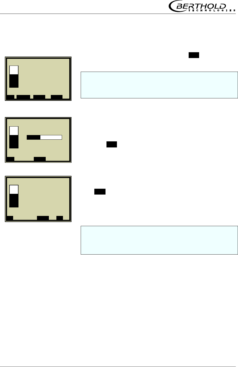
Chapter 4. Calibration
32 Micro-Polar Brix LB 565
4.2.2 Sampling
The display to the left appears if you push RUN.
Note: Push the PROBE button to start measurement of the raw
data. At the same time, the laboratory sample has to be taken
and marked. The analysis may be performed later, provided the
product is not changed by this.
Sampling is in process......
Push the ..X.. button to stop the sample taking any time.
If the sample taking took place without any problem, push
the ..√.. button to store the sample in the table and the
measurement continues.
You have to repeat the process described above for each further
sample.
The second sample taking should be started only when the dis-
play shows a significant difference to the first sample taking.
1 | - | Live Display | 07.05 – 13:25
Concentration 1 av
65.50 %
Conc av. Conc act 64.35%
ESC PROBE ..▲▼.. ZOOM
1 | - | Live Display | 07.05 – 13:25
Taking Sample # 1
Conc av. Conc act 64.35%
..X.. ..▲▼..
1 | - | Live Display | 07.05 – 13:25
Save sample no. 1?
Conc av. Conc act 64.35%
..X.. ..▲▼.. ..√..
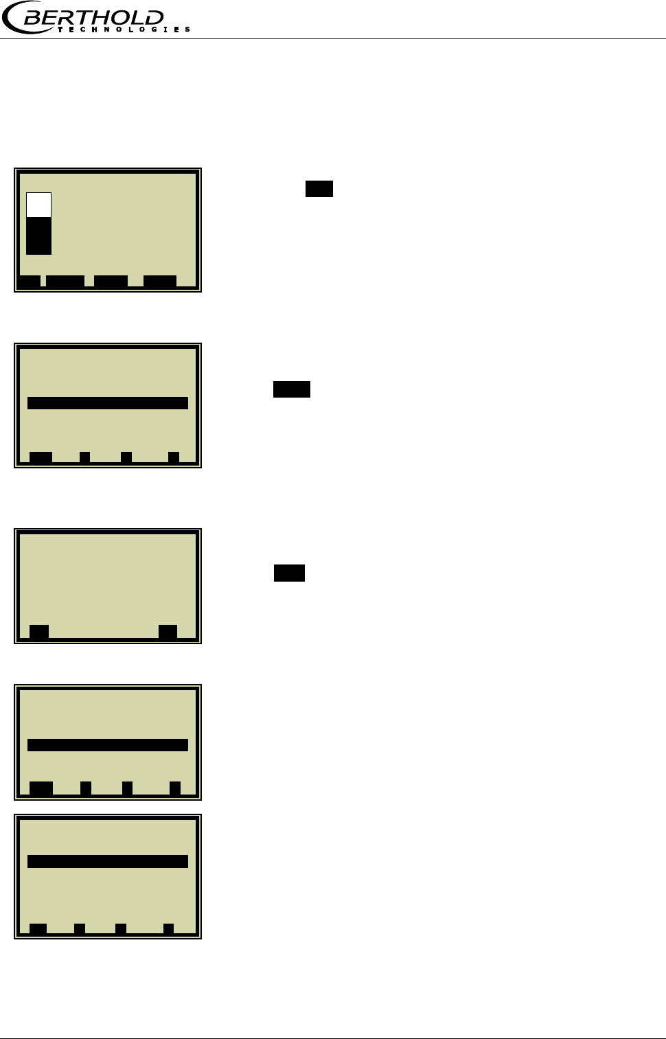
Chapter 4. Calibration
Micro-Polar Brix LB 565 33
4.2.3 Entering the Laboratory Values
Push the ESC button to go to the main menu. A measure-
ment can be stopped only on the main menu.
Push STOP to stop the measuring system.
Push ..√.. to confirm the prompt and the measurement swit-
ches to the STOP mode.
SETUP
CALIBRATION
1 | - | Live Display | 07.05 – 13:25
Concentration 1 av
65.50 %
Conc av. Conc act 64.35%
ESC PROBE ..▲▼.. ZOOM
1 | - | LB 565 | 07.05 – 13:25
Live Display
Diagnostic
Setup
Access Level Basic
Language English
Stop ▲ ▼ ►
1 | - |Toggle Run Mode|07.05 –13:25
Switch Run Mode ?
..X.. ..√..
1 | - | LB 565 | 07.05 – 13:25
Live Display
Diagnostic
Setup
Access Level Basic
Language English
RUN ▲ ▼ ►
1 | - |Setup | 07.05 – 13:25
Comfiguration
Calibration
Input / Output
Service
Product
Change password
⌂◄ ▲ ▼ ►
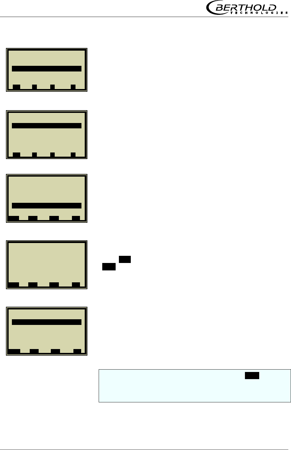
Chapter 4. Calibration
34 Micro-Polar Brix LB 565
CALIBRATE CONC
SAMPLING
LAB VALUE
Push DEL to delete default value, enter new value and push
..√.. to confirm.
NEXT SAMPLE
and repeat the step described above with the next sample.
After you have entered the last sample, push the ◄ button to
return to the calibration menu. (short push – one page, longer
push of the button – you get back to the Calibration menu im-
mediately)
1 | - | Calibration | 07.05 – 13:25
System Adjust
Calibrate Conc
Advanced
⌂◄ ▲ ▼ ►
1 | - |Calibrate Conc| 07.05 –13:25
Sampling
Calibr. autom.
Calibr. manual
Tuning
View
⌂◄ ▲ ▼ ►
1 | 1/1 | Sample # 1 | 07.05 –13:25
Next sample
Actice Yes
Meas value 65.50 %
Lab value 0.00 %
Advanced
◄ DEL ▲▼ ..
√
..
1 | 1/1 | Sample # 1 | 07.05 –13:25
Lab value
0.00| %
◄ DEL ▲▼ ..
√
..
1 | 1/1 | Sample # 1 | 07.05 –13:25
Next sample
Active Yes
Meas value 65.50 %
Lab value 72.40 %
Advanced
◄ DEL ▲▼ ..
√
..
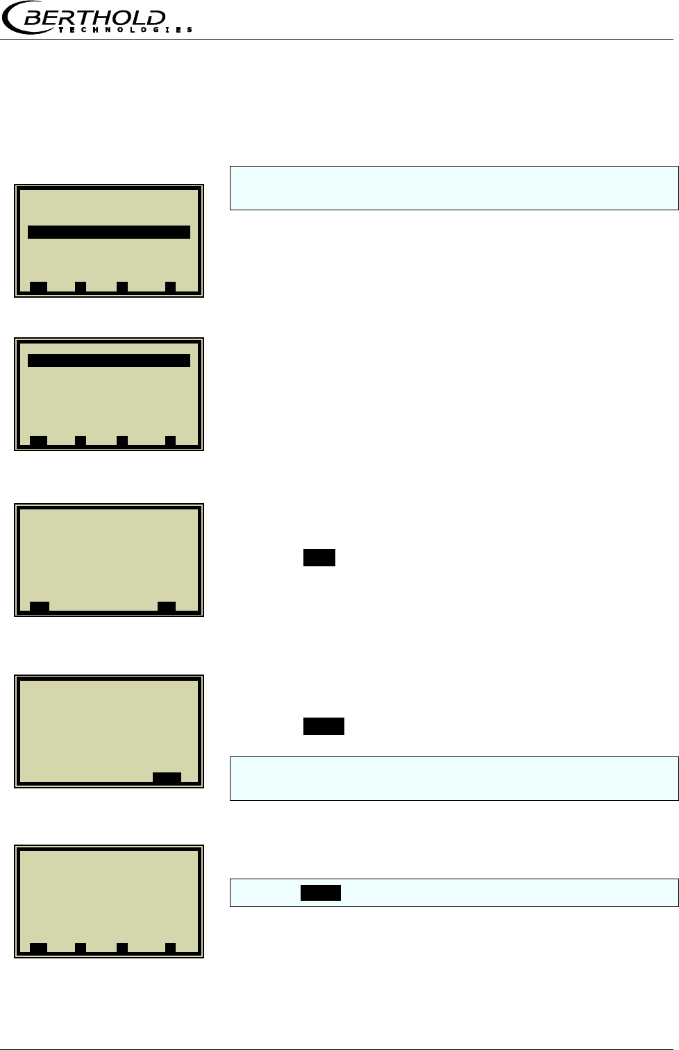
Chapter 4. Calibration
Micro-Polar Brix LB 565 35
4.2.4 Automatic Calibration
Phase calibration including the enabled compensation is carried
out during automatic calibration.
CALIBR. AUTOM.
START CALIBR.
Push the ..√.. button to start the calibration.
Push the ..OK.. button to confirm calibration.
When calculating the new coefficient set, the factor and offset
will be reset (factor 1.00000 and offset 0.000).
Push the ..⌂◄.. button four times to return to the main menu.
1 | - | Calibration | 07.05 –13:25
Calibrate now ?
..X.. ..
√
..
1 | - |Calibr. autom.| 07.05 –13:25
Start Calibr.
⌂◄ ▲ ▼ ►
1 | - |Calibrate Conc| 07.05 –13:25
Sampling
Calibr. autom.
Tuning
View
⌂◄ ▲ ▼ ►
1 | - | Calibrate Conc | 07.05 –13:25
Calibrated !
..OK..
1 | - |Calibrate Conc| 07.05 –13:25
Sampling
Calibr. autom.
Tuning
View
⌂◄ ▲ ▼ ►
Chapter 4. Calibration
36 Micro-Polar Brix LB 565
4.3 Manual Calibration
Manual calibration is possible only on the Advanced level.
Prerequisites for manual calibration are chapters
4.1 System Calibration
4.2 Start Calibration
4.2.1 Tuning
4.2.2 Sampling and
4.2.3 Entering the Laboratory Values
4.3.1 Manual Calibration with One Concentration
If the display depicted to the left is not visible, do the follow-
ing on the live display:
ESC|SETUP|CALIBRATION|CALIBRATE CONC|
CALIBR. MANUAL
CAL. ORDER
LINEAR
Quadratic calibration is possible only for a calibration with three
and more samples.
1 | - |Calibrate Conc| 07.05 –13:25
Sampling
Calibr. autom.
Calibr. manual
Tuning
View
⌂◄ ▲ ▼ ►
1 | - | Calibr. manual | 07.05 –13:25
Cal. Order Linear
Cal. Base Phase
Coefficients
Start Calibr.
⌂◄ ▲ ▼ ►
1 | - | Calibr. manual | 07.05 –13:25
Cal. Order
Linear
Quadratic
⌂◄ ▲ ▼ ►
Chapter 4. Calibration
Micro-Polar Brix LB 565 37
CAL. BASE
PHI (phase measurement)
The calibration base is selected depending on the number of
samples and their raw data. Initial calibration should be as sim-
ple as possible, since calibration can be optimized any time.
START CALIBRATION
Push the ..√.. button to start the calibration, push ..X.. to go
back one page without calibration.
..OK.. accepts the calibration and changes to the next dis-
play.
1 | - | Calibr. manual | 07.05 –13:25
Cal. Order Linear
Cal. Basic Phase
Coefficients
Start Calibr.
⌂◄ ▲ ▼ ►
1 | - | Calibr. manual | 07.05 –13:25
Cal. Base
Phase
Attenuation
Both
⌂◄ ▲ ▼ ►
1 | - | Calibr. manual | 07.05 –13:25
Cal. Order Linear
Cal. Base Phase
Coefficients
Start Calibr.
⌂◄ ▲ ▼ ►
1 | - | Calibration | 07.05 –13:25
Calibrate now ?
..X.. ..
√
..
1 | - | Calibration | 07.05 –13:25
Calibrated !
..OK..
Chapter 4. Calibration
38 Micro-Polar Brix LB 565
The curve to the left shows the characteristic curve lab /
measured value.
..►..
The correlation shows the average deviation of the curve
from the sample series.
..OK..
As soon as you confirm this prompt, the calibration display
appears again; from there you get back to the main menu by
pushing .⌂◄. four times and you can start the measurement
again.
1 | - | Calibration | 07.05 –13:25
►
1 | - | Calibration | 07.05 –13:25
Correlation Lab/Meas. value
0.998726
..OK..
1 | - | Calibration | 07.05 –13:25
Calibration OK?
..X.. ..
√
..
Chapter 4. Calibration
Micro-Polar Brix LB 565 39
4.3.2 Calibration with Two Concentrations
Calibration for two concentrations starts with changing the proc-
ess type as described below.
Prerequisites for manual calibration are chapters
4.1 System Calibration
4.2.1 Tuning and
4.2.2 Sampling
ADVANCED
PROCESS TYPE
2 CONC
Push the ..√.. button to accept the selected process type
and push the .⌂◄. button once to get to the following dis-
play.
CALIBRATE CONCENTRATION 1
1 | - | Calibration | 07.05 – 13:25
System Adjust
Calibrate Conc
Calibrate Conc2
Advanced
⌂◄ ▲ ▼ ►
1 | - | Calibration | 07.05 – 13:25
System Adjust
Calibrate Conc
Advanced
⌂◄ ▲ ▼ ►
1| - | Advanced | 07.05 –13:25
Num. Cal. Sweeps 10
Process Type
⌂◄ ▲ ▼ ►
1| - |Advanced | 07.05 –13:25
Process Type
1 Conc.
2 Conc.
Split Conc.
.ESC. ..?.. ▲▼ ..
√
..
Chapter 4. Calibration
40 Micro-Polar Brix LB 565
SAMPLING
There is only one sample table for both calibrations.
The lab values have to be entered for all samples used for cali-
bration of concentration 1. All other samples have to be disabled
(active.... yes/no).
LAB VALUE
Delete default value with DEL, enter new value and confirm
with ..√...
NEXT SAMPLE
with next sample.
ACTIVE
Disable sample.
1 | 1/4 | Sample # 1 | 07.05 – 13:25
Lab value
60.40 | %
ESC ..?.. DEL ..
√
..
1 | - |Calibrate Conc | 07.05 –13:25
Sampling
Calibr. autom.
Calibr. manual
Tuning
View
⌂◄ ▲ ▼ ►
1 | 1/4 | Sample # 1 | 07.05 –13:25
Next sample
Active Yes
Meas value 65.50 %
Lab value 0.00 %
Advanced
◄ DEL ▲▼ ..
√
..
1 |1 /4 | Sample # 1 | 07.05 –13:25
Next sample
Active Yes
Meas value 65.50 %
Lab value 60.40 %
Advanced
◄ DEL ▲▼ ..
√
..
1 |2 /4 | Sample # 2 | 07.05 –13:25
Next sample
Active Yes
Meas value 74.35 %
Lab value 67.80 %
Advanced
◄ DEL ▲▼ ..
√
..
Chapter 4. Calibration
Micro-Polar Brix LB 565 41
NO
Make sure that all samples have been processed and only those
samples are active which are relevant for this calibration.
Push ◄ to return to the calibration page.
Automatic as well as manual calibration is possible in this cali-
bration mode. For non-professional users we recommend the
automatic mode.
START CALIBRATION
Push the ..√.. button to start the calibration; push ..X.. to re-
turn one page without calibration.
1 | 2/4 | Sample # 2 | 07.05 – 13:25
Active
No
Yes
ESC ..?.. DEL ..
√
..
1 |2 /4 | Sample # 2 | 07.05 –13:25
Next sample
Active No
Meas value 74.35 %
Lab value 67.80 %
Advanced
◄ DEL ▲▼ ..
√
..
1 | - |Calibrate Conc | 07.05 –13:25
Sampling
Calibr. autom.
Calibr. manual
Tuning
View
⌂◄ ▲ ▼ ►
1 | - | Calibration | 07.05 –13:25
Calibrate now ?
..X.. ..
√
..
1 | - |Calibr. autom. |07.05 –13:25
Start Calibr.
⌂◄ ▲ ▼ ►
Chapter 4. Calibration
42 Micro-Polar Brix LB 565
Push ..OK.. to accept the calibration and to change to the
next display.
Push .⌂◄. twice to return two pages.
CALIBRATE CONCENTRATION 2
Repeat the steps as described above for concentration 2; all
samples have to be enabled again in the sample table. Now you
have to disable all samples which are not used for concentration
2.
SAMPLING
1 | - | Calibration | 07.05 –13:25
Calibrated !
..OK..
1 | - |Calibr. autom. |07.05 –13:25
Start Calibr.
⌂◄ ▲ ▼ ►
1 | - | Calibration | 07.05 – 13:25
System Adjust
Calibrate Conc
Calibrate Conc2
Advanced
⌂◄ ▲ ▼ ►
1 | - |Calibrate Conc2|07.05 –13:25
Sampling
Calibr. autom.
Calibr. manual
Tuning
View
⌂◄ ▲ ▼ ►
Chapter 4. Calibration
Micro-Polar Brix LB 565 43
4.3.3 Calibration with Split Value
With this type of calibration, two characteristic curves (concen-
trations) are combined in one measuring range; their point of
intersection defines the split value.
ADVANCED
PROCESS TYPE
SPLIT CONC
Push the ..√.. button to accept the selected process type
and push the .⌂◄. button once to go to the display depicted
below.
The displayed split value has been set by the manufacturer,
but has to be adapted to the respective application.
The sample measurement should be selected such that the last
sample of the lower concentration is fairly close to the first sam-
ple measurement of the upper concentration. Ideally, the last
sample of the initial concentration is the first sample of the final
concentration.
1 | - | Calibration | 07.05 – 13:25
System Adjust
Calibrate Conc
Advanced
⌂◄ ▲ ▼ ►
1| - | Advanced | 07.05 –13:25
Num Cal. Sweeps 10
Process Type
⌂◄ ▲ ▼ ►
1| - | Advanced | 07.05 –13:25
Process Type
1 Conc.
2 Conc.
Split Conc.
.ESC. ..?.. ▲▼ ..
√
..
1| - | Advanced |07.05 –13:25
Num. Cal. Sweeps 10
Process Type Split Conc.
Split Value 75.00 %
⌂◄ ▲ ▼ ►
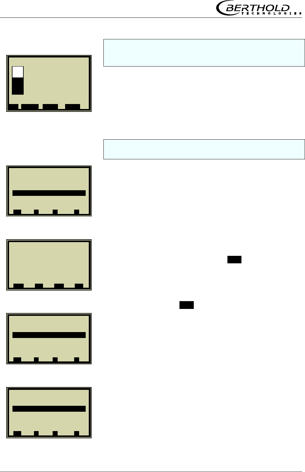
Chapter 4. Calibration
44 Micro-Polar Brix LB 565
The sample measurement is carried out continuously over the
entire measuring range with the display depicted to the left. See
chapter 4.2.2 Sampling.
After completion of sampling, the individual samples will be
enabled or disabled during input of the laboratory values, re-
lative to the set split values. All samples smaller or equal to
the split value will be assigned to the lower concentration
range and all samples above to the upper concentration ran-
ge.
The split value to be set must correspond to the point of inter-
section of both calibration curves.
SPLIT VALUE
Enter the split value and confirm with ..√...
Push the Home button .⌂◄. to return to the calibration page.
CALIBRATE CONC
CALIBR. AUTOM.
The lower concentration is now calibrated. Then select
CONC2 and repeat the calibration process.
Back to the main menu and start the measurement.
1 | - | Live Display | 07.05 – 13:25
Concentration 1 av.
65.50 %
Conc av. Conc act 64.35%
ESC PROBE ..▲▼.. ZOOM
1| - |Advanced | 07.05 –13:25
Num. Cal. Sweeps 10
Process Type Split Conc.
Split Value 75.00 %
⌂◄ ▲ ▼ ►
1| - | Advanced | 07.05 –13:25
Split Value
75.00 | %
ESC ..?.. DEL ..
√
..
1 | - | Calibration | 07.05 – 13:25
System Adjust
Calibrate Conc
Calibrate Conc2
Advanced
⌂◄ ▲ ▼ ►
1 | - |Calibrate Conc | 07.05 –13:25
Sampling
Calibr. autom.
Calibr. manual
Tuning
View
⌂◄ ▲ ▼ ►
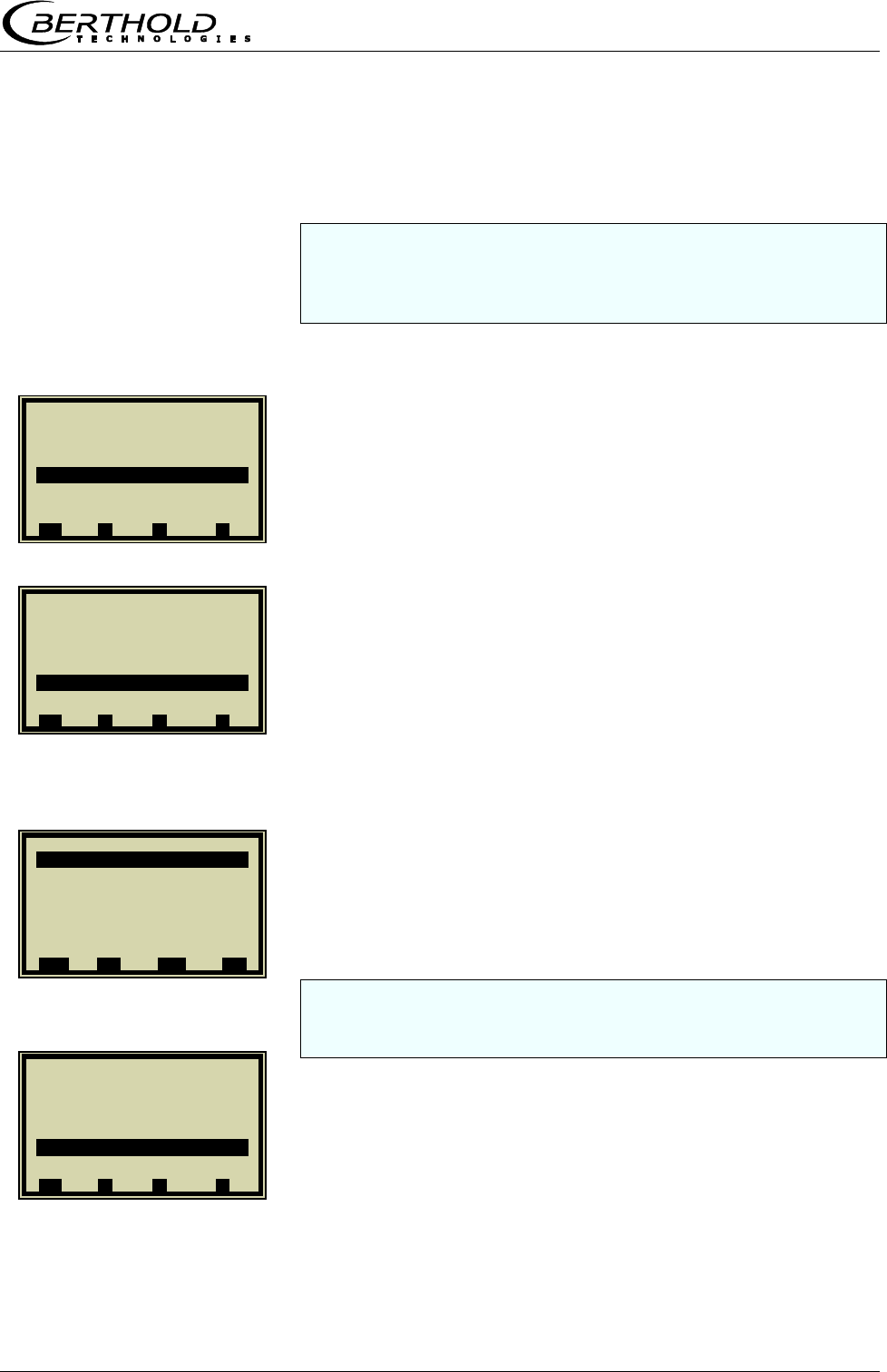
Chapter 4. Calibration
Micro-Polar Brix LB 565 45
4.3.4 Calibration with Temperature Compensation
Before running a sample measurement you have to enable the
desired compensation input and check the calibration. If all in-
puts are enabled, the measured values of all inputs will be
stored automatically in the sample table.
From the main menu, you get in the Advanced mode to the
display to the left via | SETUP | CALIBRATION | CALIBRATE
CONC. |
CALIBR. MANUAL
COMPENSATION
INPUT
If all inputs have been enabled during sample measurement,
you have the option to select a compensation from the list, since
all input values have been stored in the sample table.
Pt 100
1 | - |Calibrate Conc| 07.05 –13:25
Sampling
Calibr. autom.
Calibr. manual
Tuning
View
⌂◄ ▲ ▼ ►
1 | - | Calibr. manual | 07.05 –13:25
Cal. Order Linear
Cal. Base Phase
Coefficients
Compensation
Start Calibr.
⌂◄ ▲ ▼ ►
1 | - |Compensation| 07.05 –13:25
Input
None
Current In 1
Current In 2
Pt 100
⌂◄ ▲ ▼ ►
1 | - |Compensation | 07.05 –13:25
Input None
Mode Additive
Order Linear
Ref. Temp. 0.00
TC_Phi 1 0.00000
TC_dB 1 0.00000
ESC ..?.. ▲▼ ..
√
..
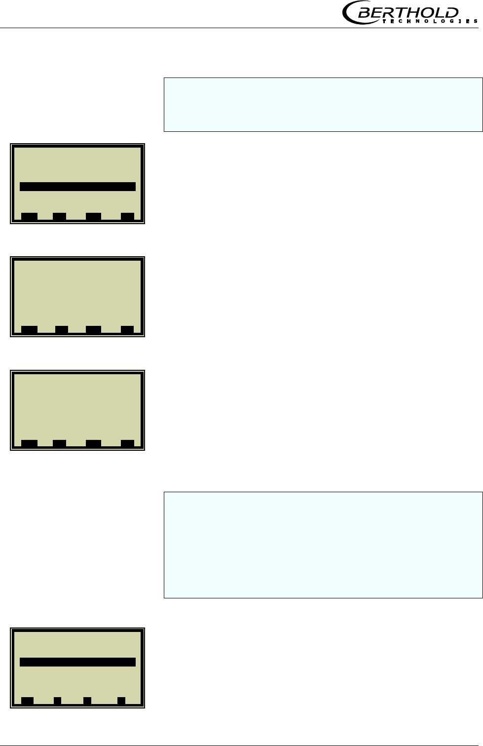
Chapter 4. Calibration
46 Micro-Polar Brix LB 565
You can select additive or multiplicative mode and set the or-
der to linear or quadratic. If you select automatic calibration
mode, the above modes will be calculated automatically. This is
recommended for non-professional users.
REF TEMP
Enter the average operating temperature and confirm.
The coefficients TC_Phi 1 and TC_dB 1 are automatically cal-
culated during calibration.
If you have completed the entries described above and have
carried out the steps described in chapters
4.1 System calibration
4.2.1 Tuning
4.2.2 Sampling and
4.2.3 Entering the Lab Values
you may proceed with the calibration as described below.
CALIBR. AUTOM.
1 | - |Compensation | 07.05 –13:25
Ref. Temp.
80.00 | °C
ESC ..?.. DEL ..
√
..
1 | - |Compensation | 07.05 –13:25
Input Pt 100
Mode Additive
Order Linear
Ref. Temp. 0.00°C
TC_Phi 1 0.00000
TC_dB 1 0.00000
ESC ..?.. ▲▼ ..
√
..
1 | - |Compensation | 07.05 –13:25
Input Pt 100
Mode Additive
Order Linear
Ref.Temp. 80.00°C
TC_Phi 1 0.00000
TC_dB 1 0.00000
ESC ..?.. ▲▼ ..
√
..
1 | - |Calibrate Conc1|07.05 –13:25
Sampling
Calibr. autom.
Calibr. manual
Tuning
View
⌂◄ ▲ ▼ ►
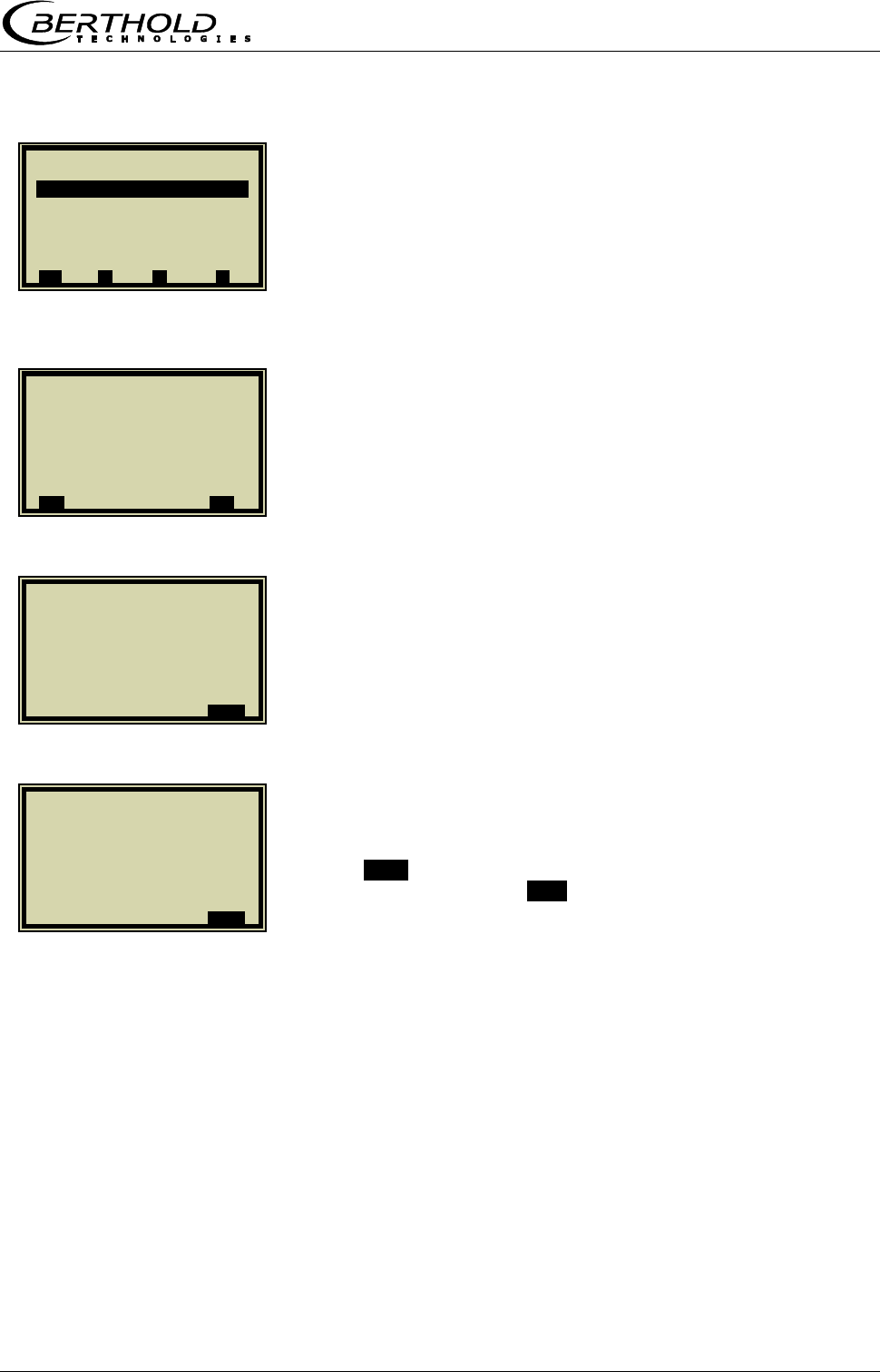
Chapter 4. Calibration
Micro-Polar Brix LB 565 47
START CALIBR.
Start calibration process.
Push .O.K. to confirm the calibration. Calibration is finished.
Push the Home button .⌂◄. four times to return to the main
menu and to start a measurement.
1 | - |Calibr. autom. |07.05 –13:25
Start Calibr.
Compensation Pt 100
⌂◄ ▲ ▼ ►
1 | - | Calibr. autom. | 07.05 –13:25
Calibrate now ?
..X.. ..
√
..
1 | - | Calibr. autom. | 07.05 –13:25
Calibrating...
..OK..
1 | - | Calibr. autom. | 07.05 –13:25
Calibrated !
..OK..

Chapter 5. Password
48 Micro-Polar Brix LB 565
Chapter 5. Password
The measuring system can be protected by passwords a-
gainst unauthorized access.
5.1 Password
The following access levels are available.
Read only
The measuring system cannot be started and stopped. You
can only switch from the live display to Diagnostic and to Ac-
cess Level.
Basic
On the Basic level you can make essential entries, and stop
and start the system.
Profi
The Profi mode allows additional entries in the process type
menu, calibration menu and opens the Service menu.
Service
The Service level is reserved for technical service.
You have to enter a password to change from the access
level „Read only“ to „Basic“ or „Profi“.
At the time of delivery, this password is
PASS1
Changing from Profi to Basic or vice versa is possible without
password. You can change the password on the Profi or Basic
level.
Chapter 6. Inputs / Outputs
Micro-Polar Brix LB 565 49
Chapter 6. Inputs / Outputs
The measuring system includes two separate floating current
outputs.
6.1 Current Outputs
Current outputs 1 and 2 can be assigned to the concentra-
tions for calibration with two concentrations.
You get to the setup display as follows.
SETUP
INPUT/OUTPUT
CURRENT OUTPUT
Now you can select the respective current output and assign
it to the concentration after calibration.
1 | - | LB 565 | 07.05 – 13:25
Live Diplay
Diagnostic
Setup
Access Level Basic
Language English
RUN ▲ ▼ ►
1 | - |Setup | 07.05 – 13:25
Configuration
Calibration
Input / Output
Service
Product
⌂◄ ▲ ▼ ►
1 | - |Input / Output | 07.05 –13:25
Current Output
Current Input
Pt 100
Digital Output
Digital Input
⌂◄ ▲ ▼ ►
1 | - |Current Output | 07.05 –13:25
Current Out 1
Current Out 2
⌂◄ ▲ ▼ ►
Chapter 6. Inputs / Outputs
50 Micro-Polar Brix LB 565
6.1.1 Current Output Setup
CURRENT_OUT 1
ASSIGNMENT
CONC
Select and confirm with ..√...
In case of two concentrations and outputs enabled, the assign-
ment can be chosen as needed.
UPPER VALUE
Delete the old value with DEL. Enter the new limit value and
confirm with ..√...
Set the lower value also as described above.
1 | - |Current Output | 07.05 –13:25
Current Out 1
Current Out 2
⌂◄ ▲ ▼ ►
1 | - | Current Out 1 | 07.05 –13:25
Assignmet Conc.
Upper Value 95.00 %
Lower Value 60.00 %
Test / Adjust
Error current
⌂◄ ▲ ▼ ►
1 | - | Current Out 1|07.05 –13:25
Assignment
Conc.
Conc. 2
Current In 1
Current In 2
Pt 100
.ESC. ..?.. ▲▼ ..
√
..
1 | - |Current Out 1|07.05 –13:25
Assignment Conc.
Upper value 95.00 %
Lower value 60.00 %
Test / Adjust
Error current
⌂◄ ▲ ▼ ►
1 | - |Current Out 1| 07.05 –13:25
Upper value
95.00 | %
.ESC. ..?.. DEL ..
√
..
Chapter 6. Inputs / Outputs
Micro-Polar Brix LB 565 51
6.1.2 Test and Adjustment
TEST / ADJUST
DAC TRIM
! CAUTION: Current output 1 can only be set between 4
and 20 mA, since it is foreseen for a Hart® communicator.
Push .OK. to confirm that the process is not affected by the
measurement.
Push .OK. to confirm that the measuring system is con-
nected.
Push .OK. to confirm.
1 | - |Current Out 1|07.05 –13:25
Assignment Conc.
Upper value 95.00 %
Lower value 60.00 %
Test / Adjust
Error current
⌂◄ ▲ ▼ ►
1 | - |Test / Adjust | 07.05 –13:25
Loop test
DAC trim
Live current 4.00 mA
⌂◄ ▲ ▼ ►
1 | - | Trim Cout | 07.05 –13:25
Loop should be removed
from automatic control
..X.. .OK.
1 | - | Trim Cout | 07.05 –13:25
Connect reference meter!
..X.. .OK.
1 | - | TrimCout | 07.05 –13:25
Setting Current Output
To 4 mA
..X.. .OK.
Chapter 6. Inputs / Outputs
52 Micro-Polar Brix LB 565
Read off display of measuring system and enter value.
4 mA value adjusted.
Push the .OK. button to confirm.
Read off display of measuring system and enter value.
Adjustment finished.
To check the current loop and possibly connected remote dis-
plays, you can set a current between 4 and 20 mA via the test
function. If you quit the test function, the system automatically
switches back to the live current.
1 | - | Trim Cout | 07.05 –13:25
Enter meter value
3.80 | mA
.ESC. .DEL. ..
√
..
1 | - | Trim Cout | 07.05 –13:25
4 mA adjusted
..X.. .OK.
1 | - | Trim Cout | 07.05 –13:25
Setting Current Output
to 20 mA
..X.. .OK.
1 | - | Trim Cout | 07.05 –13:25
Enter meter value
19.80 | mA
.ESC. .DEL. ..
√
..
1 | - | Trim Cout | 07.05 –13:25
20 mA adjusted
..X.. .OK.
1 | - |Test / Adjust | 07.05 –13:25
Loop test
DAC trim
Live current 15.00 mA
⌂◄ ▲ ▼ ►
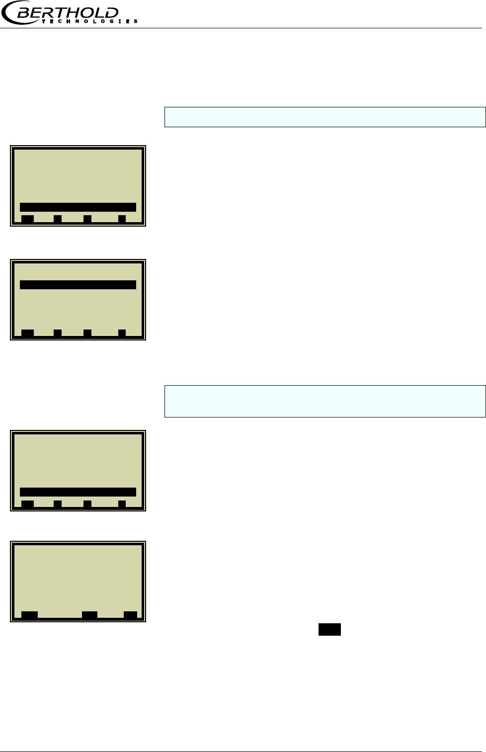
Chapter 6. Inputs / Outputs
Micro-Polar Brix LB 565 53
6.1.3 Error Current
Different signal effects can be assigned to the output current.
ERROR CURRENT
ALARM MODE
Fixed values, Hold or freely adjustable values between 0 and
24 mA can be assigned.
VALUE
With this setting, you can default any current value for the
error case.
! CAUTION: The current output 1 can only be set between
3.5 mA and 24 mA. [HART®]
Enter value and confirm with ..√...
1 | - |Current Out 1|07.05 –13:25
Assignment Conc.
Upper value 95.00 %
Lower value 60.00 %
Test / Adjust
Error current
⌂◄ ▲ ▼ ►
1 | - | Error current | 07.05 –13:25
Alarm Mode
Value 22.00 mA
⌂◄ ▲ ▼ ►
1 | - | Error current |07.05 –13:25
Alarm mode
22.00 mA
3.5 mA
Hold
Value
⌂◄ ▲ ▼ ►
1 | - |Error current| 07.05 –13:25
Value
3.50 mA
ESC DEL ..
√
..
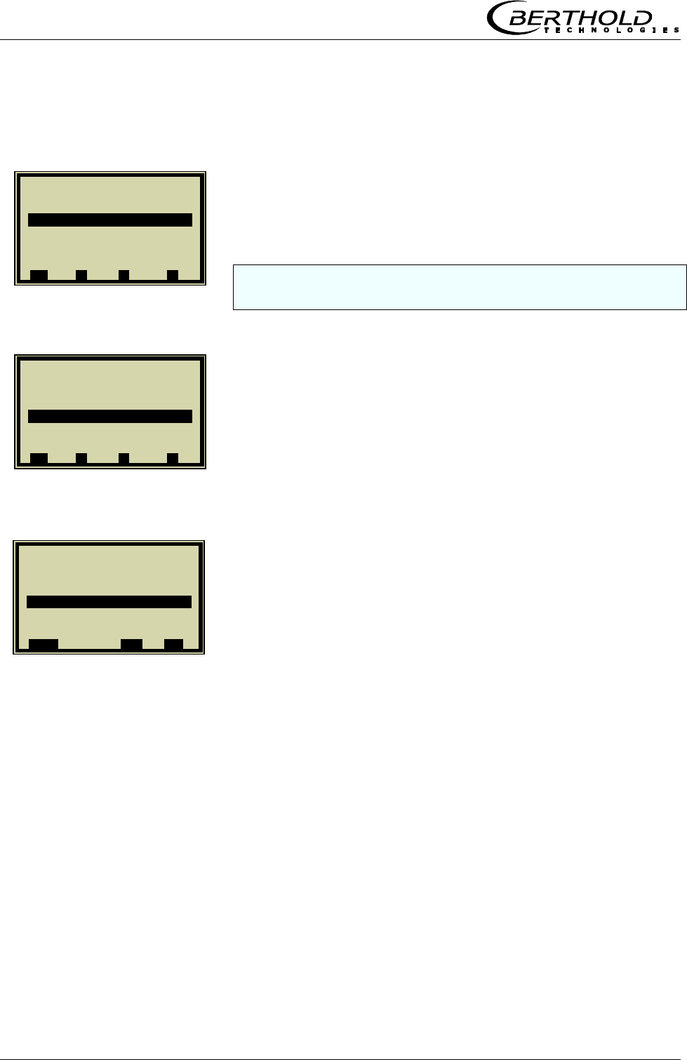
Chapter 6. Inputs / Outputs
54 Micro-Polar Brix LB 565
6.1.4 Current Output 2
CURRENT OUT 2
All settings for current output 2 have to be made in the same
manner as for output 1, with the exception of the range setting.
RANGE
After selection of the required range, carry out all setting and
calibration steps as described in chapter 6.1.2.
1 | - |Current Output | 07.05 –13:25
Current Out 1
Current Out 2
⌂◄ ▲ ▼ ►
1 | - |Current Out 2|07.05 –13:25
Assignment Conc.2
Upper value 95.00 %
Lower value 60.00 %
Range 4 - 20 mA
Test / Adjust
Error current
⌂◄ ▲ ▼ ►
1 | - |Current Out 2|07.05 –13:25
Range
0 – 20 mA
4 – 20 mA
.ESC. ▲▼ ..
√
..
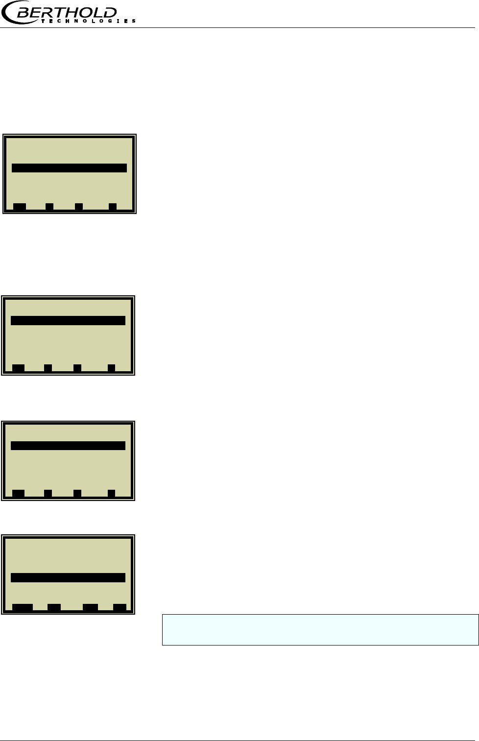
Chapter 6. Inputs / Outputs
Micro-Polar Brix LB 565 55
6.2 Current Inputs
If the window below is not displayed, you can invoke it on
the main menu via |SETUP |INPUT/OUTPUT |
CURRENT INPUT
6.2.1 Enabling the Current Input
CURRENT IN 1
ENABLED
ENABLING
If a measurement is running, enabling an adjusted current input
which is not used may cause an error.
1 | - |Input / Output | 07.05 –13:25
Current Output
Current Input
Pt 100
Digital Output
Digital Input
⌂◄ ▲ ▼ ►
1 | - |Current Input | 07.05 –13:25
Current In 1
Current In 2
⌂◄ ▲ ▼ ►
1 | - |Current In 1 | 07.05 –13:25
Enabled nein
DAC trim
Live current 4.00 mA
⌂◄ ▲ ▼ ►
1 | - |Current In 1 | 07.05 –13:25
Enabled
no
yes
.ESC. ..?.. ▲▼ ..
√
..
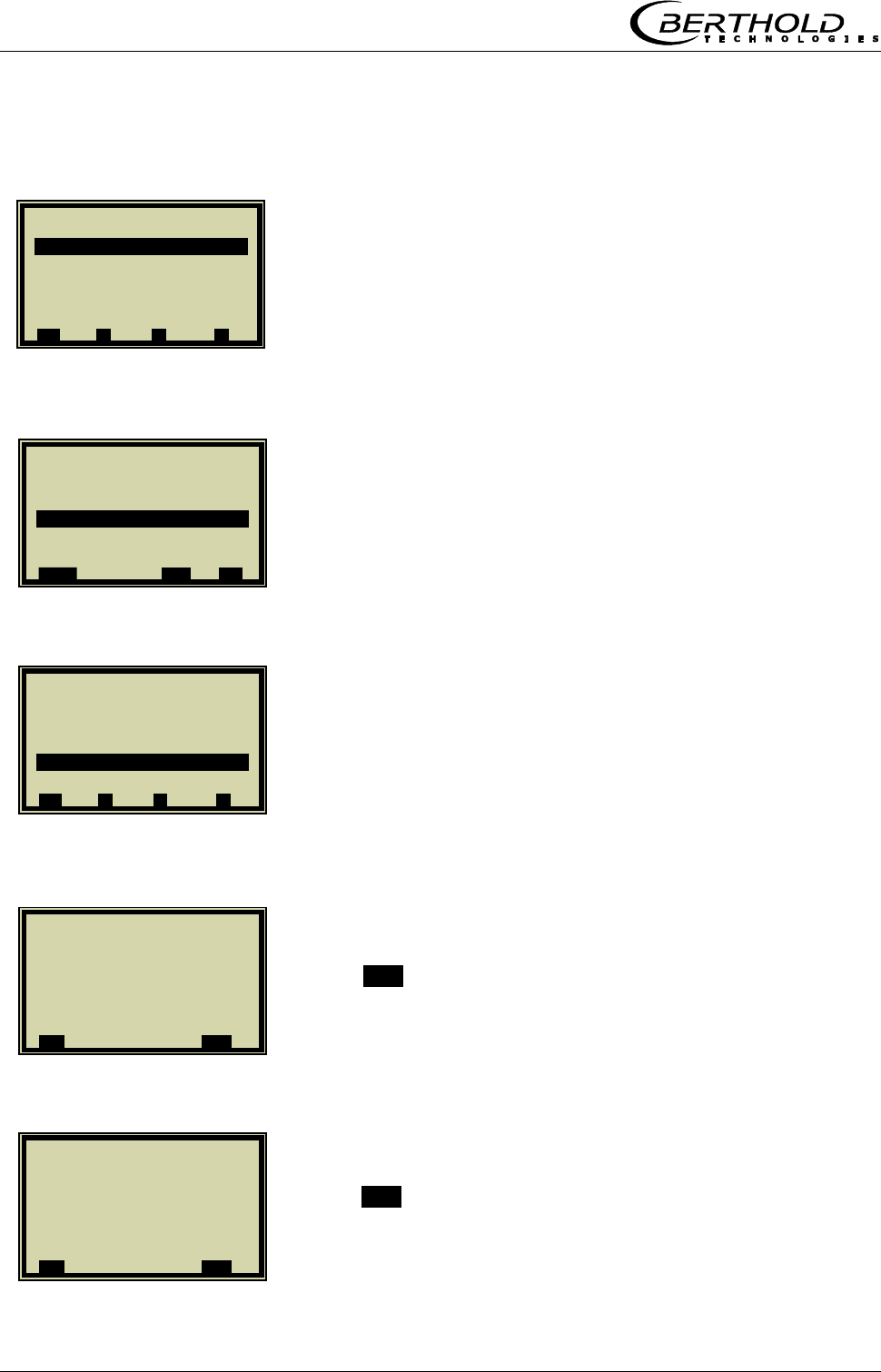
Chapter 6. Inputs / Outputs
56 Micro-Polar Brix LB 565
6.2.2 Range Setting and Adjustment
RANGE SETTING
4 – 20 mA
DAC trim
Push .OK. to confirm that the process is not affected by the
measurement.
Push .OK. to confirm that the current generator is connected.
1 | - | Current In 1 | 07.05 –13:25
Enabled ja
Range 0 – 20 mA
Upper value 100.00 °C
Lower value 0.00 ° C
DAC trim
Live current 4.00 mA
⌂◄ ▲ ▼ ►
1 | - |Current In 1| 07.05 –13:25
Range
0 – 20 mA
4 – 20 mA
.ESC. ▲▼ ..
√
..
1 | - | Current In 1 | 07.05 –13:25
Enabled yes
Range 4 – 20 mA
Upper value 100.00 °C
Lower value 0.00 ° C
DAC trim
Live current 4.00 mA
⌂◄ ▲ ▼ ►
1 | - | Trim Cin | 07.05 –13:25
Loop should be removed
from automatic control!
..X.. .OK.
1 | - | Trim Cin | 07.05 –13:25
Connect current generator!
..X.. .OK.
Chapter 6. Inputs / Outputs
Micro-Polar Brix LB 565 57
Set current generator to 4 mA.
Push the .OK. button to confirm.
Push .OK. to confirm adjustment of the lower value.
Set current generator to 20 mA.
Push the .OK. button to confirm.
Push .OK. to confirm adjustment of the lower value.
1 | - | Trim Cin | 07.05 –13:25
Set current generator
to 4 mA
..X.. .OK.
1 | - | Trim Cin | 07.05 –13:25
4 mA adjusted.
..X.. .OK.
1 | - | Trim Cin | 07.05 –13:25
Generator set to 20 mA?
..X.. .OK.
1 | - | Trim Cin | 07.05 –13:25
20 mA adjusted.
..X.. .OK.
1 | - | Trim Cin | 07.05 –13:25
Generator set to 4 mA?
..X.. .OK.
1 | - | Trim_Cin | 07.05 –13:25
Set current generator
to 20 mA
..X.. .OK.
Chapter 6. Inputs / Outputs
58 Micro-Polar Brix LB 565
Adjustment finished. The live current is displayed.
If necessary, carry out range setting and calibration of current
input 2 as described above.
6.3 Pt 100
Before enabling, you have to stop the measuring system, as the
change in configuration may lead to errors.
6.3.1 Pt 100 Enabling
PT 100
ENABLED
Select „yes“ and confirm with ..√….
1 | - |Current In 1 | 07.05 –13:25
Enabled ja
Range 4 – 20 mA
Upper value 100.00 °C
Lower value 0.00 ° C
DAC trim
Live current 4.00 mA
⌂◄ ▲ ▼ ►
1 | - |Input / Output | 07.05 –13:25
Current Output
Current Input
Pt 100
Digital Output
Digital Input
⌂◄ ▲ ▼ ►
1 | - | Pt 100 | 07.05 –13:25
Enabled no
Trim Pt 100
Pt 100 live
⌂◄ ▲ ▼ ►
1 | - | Pt 100 | 07.05 –13:25
Enabled
no
yes
ESC ▲▼ ..
√
..
Chapter 6. Inputs / Outputs
Micro-Polar Brix LB 565 59
6.3.2 Pt 100 Calibration
TRIM Pt 100
..OK..
Connect 100 Ohm resistor to the Pt100 terminals [11] [23].
Confirm once more with .O.K..
Adjustment of lower point finished.
After connection of the resistor, confirm with ..OK...
1 | - | Pt 100 | 07.05 –13:25
Enabled yes
Trim Pt 100
Pt 100 live
⌂◄ ▲ ▼ ►
1 | - |Trim Pt 100 | 07.05 –13:25
Connect 100 Ohm resistor
to Pt 100 terminals !
(for 0°C / 31.4°F adjustment)
..X.. .OK.
1 | - |Trim Pt 100 | 07.05 –13:25
100 Ohm resistor connected?
..X.. .OK.
1 | - |Trim Pt 100 | 07.05 –13:25
Lower point adjusted
..X.. .OK.
1 | - |Trim Pt 100 | 07.05 –13:25
Connect 138,5 Ohm resistor
to Pt 100 terminals !
(for 100°C / 211.4°F adjustment)
Chapter 6. Inputs / Outputs
60 Micro-Polar Brix LB 565
1 | - |Digital Output | 07.05 –13:25
Relay 1
Relay 2
Test
⌂◄ ▲ ▼ ►
Confirm prompt.
Calibration is finished.
6.4 Digital Output
The measuring system includes two changeover relay outputs
which can be assigned to the respective application.
Relay 1 is associated with LED signal 1 and relay 2 with signal 2.
6.4.1 Digital Output Assignment
From the main menu you get to the display depicted to the
left via | Setup | Input/Output | Digital Output
RELAY 2
Select the display with the arrow keys.
1 | - |Trim Pt 100 | 07.05 –13:25
Upper point adjusted.
..X.. .OK.
1 | - |Trim Pt 100 | 07.05 –13:25
138.5 Ohm resistor connected?
..X.. .OK.
1 | - | Relay 2 | 07.05 –13:25
Function No product
⌂◄ ▲ ▼ ►
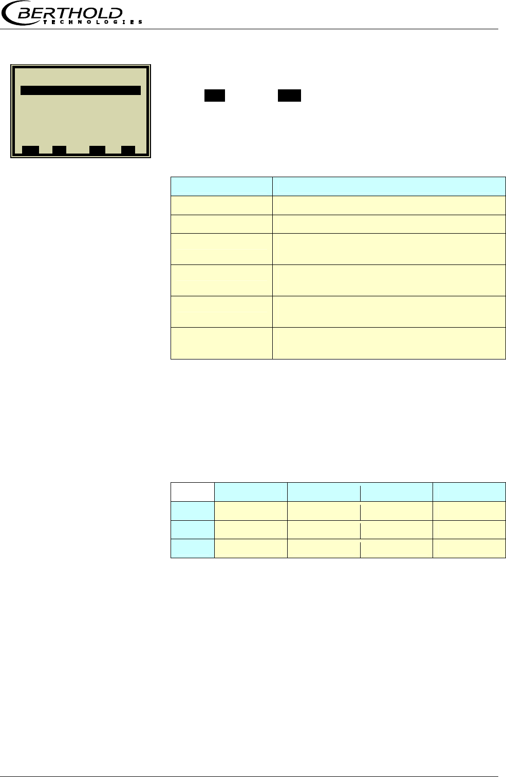
Chapter 6. Inputs / Outputs
Micro-Polar Brix LB 565 61
Push ▲▼ and then ..√.. to assign a function to the relay.
Function Description
None Relay and LED function disabled
Error In case of error, relay and LED will be set.
Hold meas. If Hold function is enabled, relay and LED
will be set.
No product If Pause detection is enabled, this will be
signaled via relay and LED.
Alarm min. The relay switches if the value falls below
the limit value to be set.
Alarm max. The relay switches if the value exceeds
the limit value to be set.
6.5 Digital Input
Different functions can be assigned to the digital inputs. See
table below:
Function1 Function2 Function3 Terminals
DI 1 None Start 12/24
DI 2 None Hold Product 13/25
DI 3 None Sample Product 14/26
For external start function, the start function has to be set to
external in the Measurement menu window.
Hold means that averaging is stopped, but the measurement
continues to run.
Sample means that sampling is started by closing the con-
tact.
1 | - | Relay 2 | 07.05 –13:25
Function
None
Error
Hold meas.
No product
Alarm min
Alarm max
ESC ..?.. ▲▼ ..
√
..
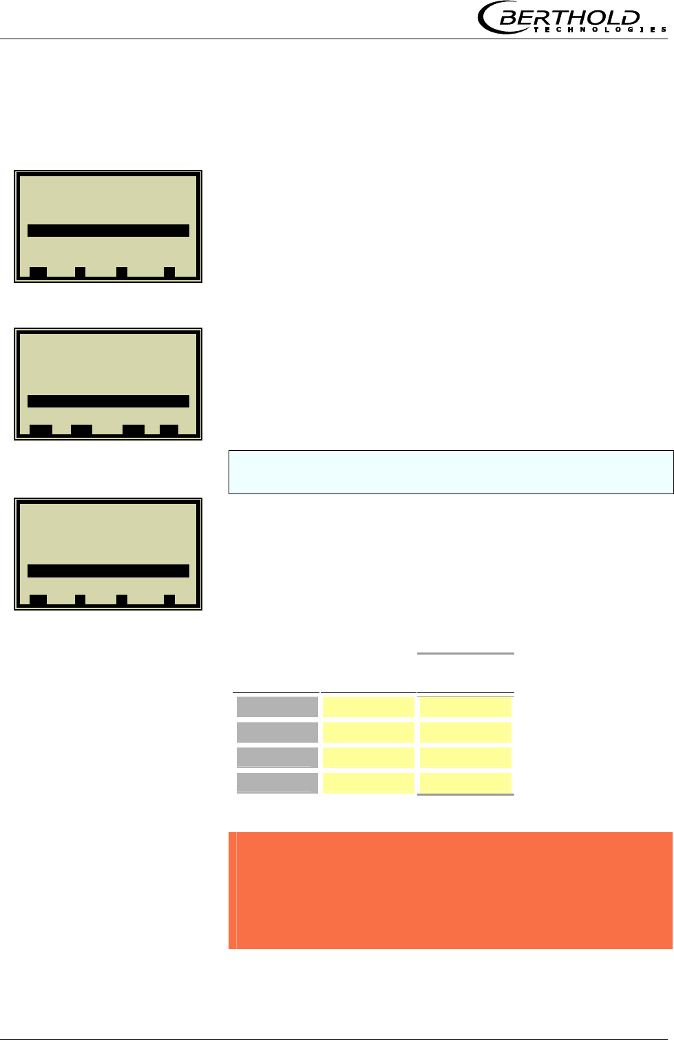
Chapter 6. Inputs / Outputs
62 Micro-Polar Brix LB 565
6.5.1 External Product Switchover
From the main menu you get to the window display depicted
to the left via |SETUP |INPUT/OUTPUT |DIGITAL IINPUT.
DI 2 FUNCTION
PRODUCT
DI 3 also has to be set to product. Please take the terminal as-
signment from the table below.
Terminals DI 2
13 / 25
DI 3
14 / 26
Product 1 Open Open
Product 2 Closed Open
Product 3 Open Closed
Product 4 Closed Closed
CAUTION!
If you change to another product, the product-specific data
will be loaded automatically, including:
Configurations data
System calibration
Calibration data
Input/Output definitions
1 | - |Digital Input |07.05 –13:25
Status
DI 1 function None
DI 2 function None
DI 3 function None
⌂◄ ▲ ▼ ►
1 | - |Digital Input |07.05 –13:25
DI 2 function
None
Hold
Product
E
SC DEL ▲▼ ..
√
..
1 | - |Digital Input |07.05 –13:25
Status
DI 1 function None
DI 2 function Produkt
DI 3 function None
⌂◄ ▲ ▼ ►
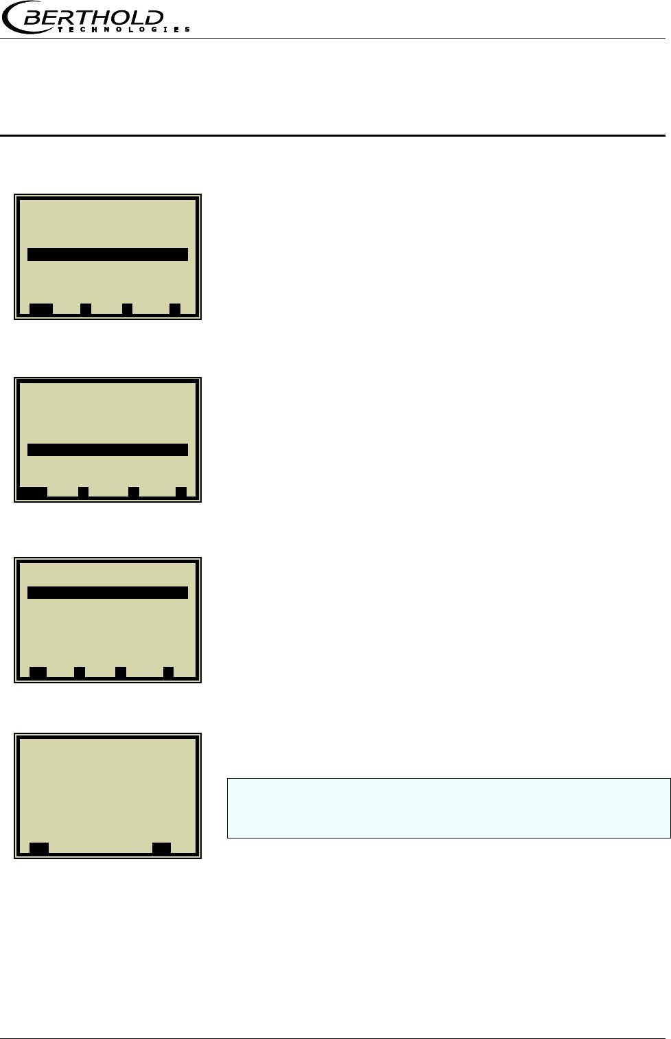
Chapter 7. Factory Settings
Micro-Polar Brix LB 565 63
Chapter 7. Factory Settings
This function allows you to reset the measuring system to its
original status.
SETUP
SERVICE
FACTORY SETTINGS
If you confirm this prompt, all parameters and configuration set-
tings will be reset to their original status, with the exception of
the sampling table and the reference measurement.
1 | - | LB 565 | 07.05 – 13:25
Live Display
Diagnostic
Setup
Access Level
Language
RUN ▲ ▼ ►
1 | - | Setup | 07.05 – 13:25
Configuration
Calibration
Input / Output
Service
Product
Change password
⌂◄ ▲ ▼ ►
1 | - | Service | 07.05 – 13:25
Factory settings
⌂◄ ▲ ▼ ►
1| - |Factory Settings| 07.05 – 13:25
Restore now?
..X.. ..
√
..

Chapter 8. Error Lists
64 Micro-Polar Brix LB 565
Chapter 8. Error Lists
8.1 Error Lists
All errors will be signaled by a red LED and a flashing RUN LED.
Error displayed on the LCD have to be confirmed. After the error
has been remedied, the LED’s are reset to the normal status.
8.1.1 Hardware Error
Battery voltage
Program memory faulty
Data memory faulty
I/O Communication trouble
8.1.2 Input Error
Error Cause
Value too high Input value is too high
Value too low Input value is too low
Table is empty Sampling has been selected without previ-
ous sample measurement
Chart data
faulty
The measuring system has determined
faulty chart data during calibration.
No chart data
available
The calculates chart data have been deleted
or calibration has not been completed.
Sampling full You have tried to measure more then 10
samples.

Chapter 8. Error Lists
Micro-Polar Brix LB 565 65
8.1.3 Measurement Error
Error Possible cause
Variance of phase
is too large
The measured phase exceeds the
permissible limit value.
Attenuation too
high
The measured attenuation exceeds the
permissible maximum value.
Current input 1 out
of range
The enabled current input has not yet
been calibrated or is not occupied.
Current input 2 out
of range
The enabled current input has not yet
been calibrated or is not occupied.
Pt 100 temperature
out of range
The enabled Pt 100 input has not yet
been calibrated or is not occupied.
Concentration out
of range
The concentration calculated on the
basis of the raw data lies outside the
valid measuring range.
Concentration 2
out of range
The concentration calculated on the
basis of the raw data lies outside the
valid measuring range.
All remedied measurement errors have to be confirmed with
O.K. so that the measuring system can return to the live display.
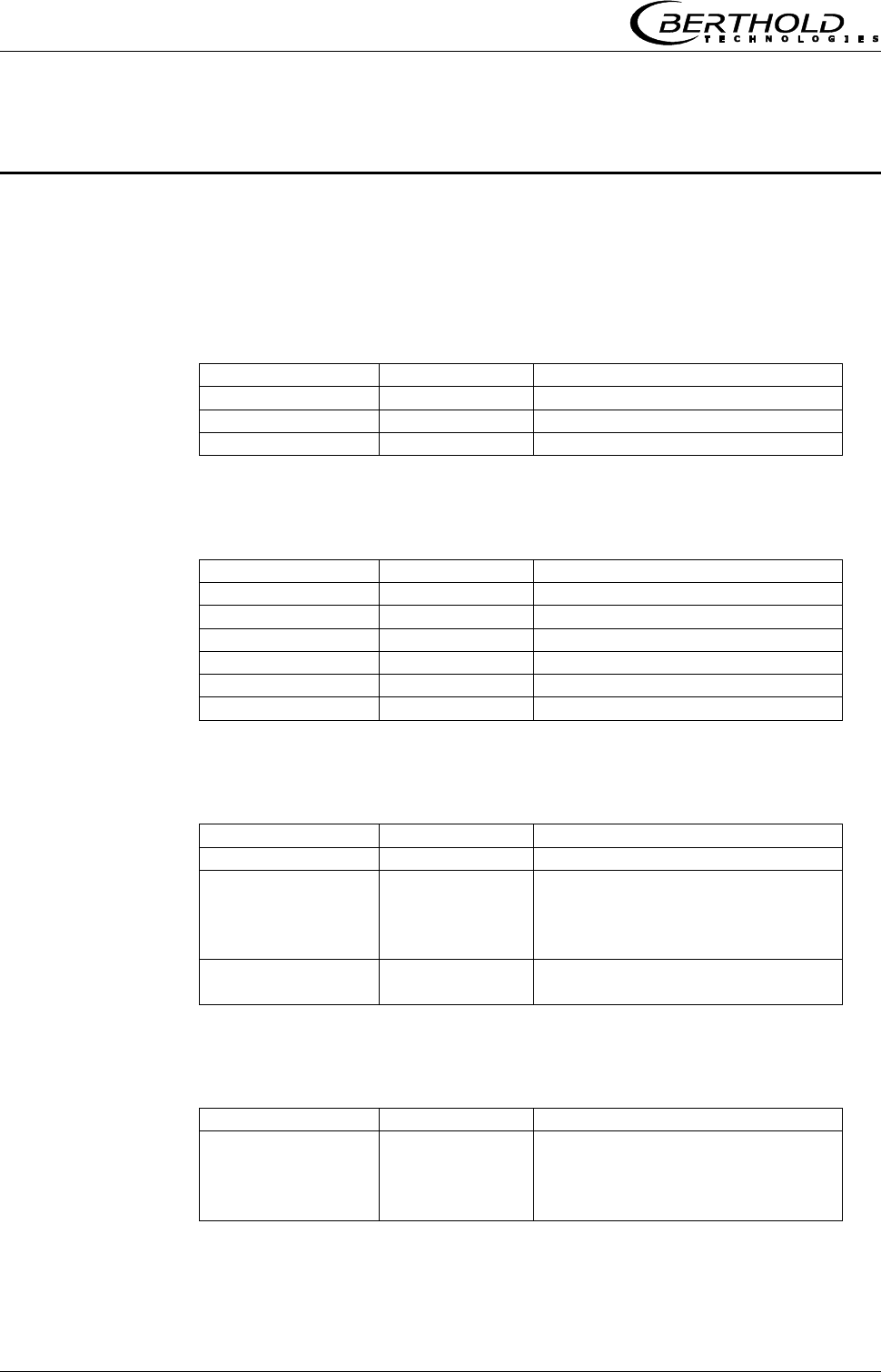
Chapter 9. Calibration Data Sheet
66 Micro-Polar Brix LB 565
Chapter 9. Calibration Data Sheet
9.1 Configuration
9.1.1 General
General Default Setting
Date 01.06.04
Time 13:00
Tag -
9.1.2 Measurement
Measurement Default Setting
Meas. mode continuous
Start mode keyboard
Averaging 20
Reset averaging no
Marker Mark1
Units %
9.1.3 Plausibility
Plausibility Default Setting
Process limits 60.0 – 100.0
Phase measure-
ment
Variance
Ratio Phi/dB
100.00
6.0
Pause detection yes
-15.0 dB
9.1.4 Microwave
Microwave Default Setting
Cable
Ref. cable length
Signal cable
length
4.00 m
4.00 m
Chapter 9. Calibration Data Sheet
Micro-Polar Brix LB 565 67
9.2 Product
Product Default Setting
Product 1
9.3 Input / Output
9.3.1 Current Output
Current_out 1 Default Setup
Assignment Conc.
Upper value 95.00
Lower value 60.00
Test/Calibration O.K.
Error current Hold
Current_out 2 Default Setting
Assignment conc. 2
Upper value 95.00
Lower value 60.00
Range 4 – 20 mA
Test/Calibration O.K.
Error current Hold
9.3.2 Current Input
Current_in 1 Default Setting
Enabled no
Range 4 – 20 mA
Upper value 100.00
Lower value 0.00
Calibration O.K.
Live current 17.05 mA
Current_in 2 Default Setting
Enabled No
Range 4 – 20 mA
Upper value 100.00
Lower value 0.00
Calibration O.K.
Live current 17.05 mA
Chapter 9. Calibration Data Sheet
68 Micro-Polar Brix LB 565
9.3.3 Pt 100 Input
Pt 100 Default Setting
Enabled no
Pt 100
Calibration
O.K.
Pt 100 Live 99.99 °C
9.3.4 Digital Output
Digital output Default Setting
Relay 1 Error
Relay 2 No Product
9.3.5 Digital Input
Digital input Default Setting
DI 1 function none
DI 2 function none
DI 3 function none
9.4 Calibration Data
9.4.1 Calibration Coefficients
Calibration Default Setting
Calibration order linear
Calibration Basic phase
Coefficients
A1
A2
B1
B2
C
-0.19
0.0
0.0
0.0
75.00
Compensation
Mode
Order
Ref. temp.
TC_Phi 1
TC_Phi 2
TC_Attn 1
TC_Attn 2
none
additive
linear
0.00
0.00000
0.00000
0.00000
0.00000

Calibration Data Sheet
Micro-Polar Brix LB 565 69
9.4.2 Sampling Table
No. Active Meas. value Lab value Current_in 1 Current _in 2 Pt 100 Phi (m) Attenuation
1
2
3
4
5
6
7
8
9
10

70 Micro-Polar Brix LB 565
Notes

Micro-Polar Brix LB 565 71
Notes