Berthold Technologies FCC02X03 Concentration / Moisture / Dry Mass / Density Measuring System User Manual LB 567
Berthold Technologies Concentration / Moisture / Dry Mass / Density Measuring System LB 567
UserManual.wiki
>
Berthold Technologies
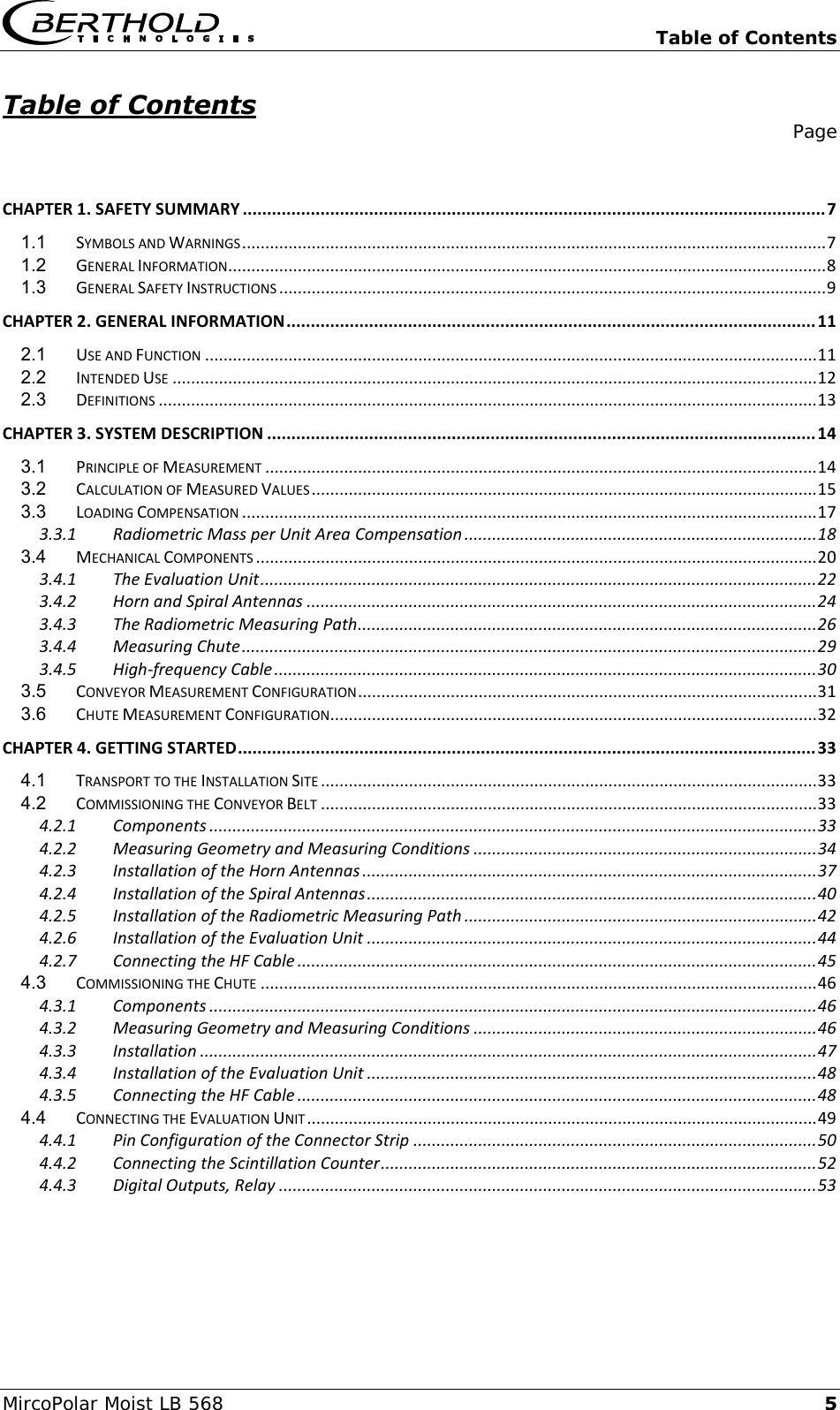
>
FCC02X03 User Manual
UserManual.pdf
Navigation menu
Upload a User Manual
Namespaces
Wiki Guide
HTML
PDF
Info
Views
User Manual
Discussion / Help
Navigation


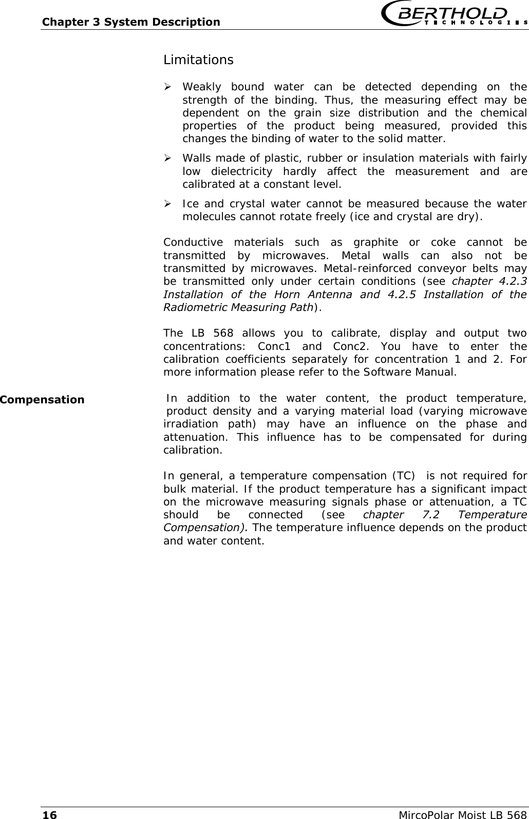
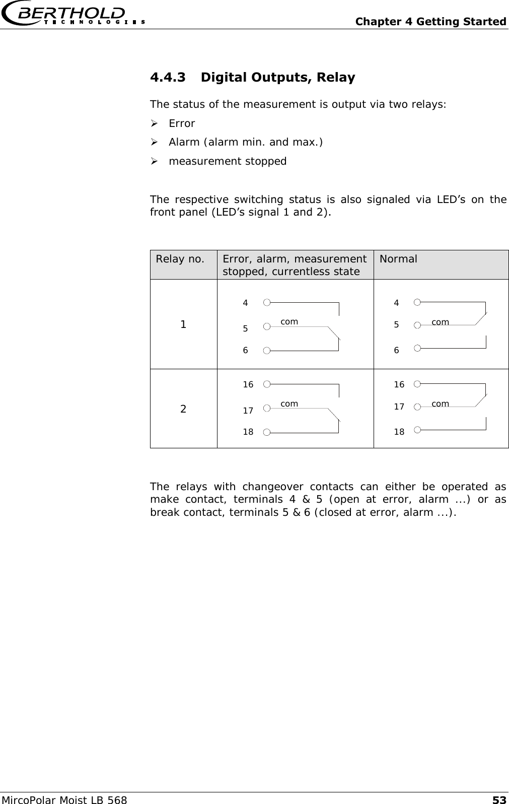
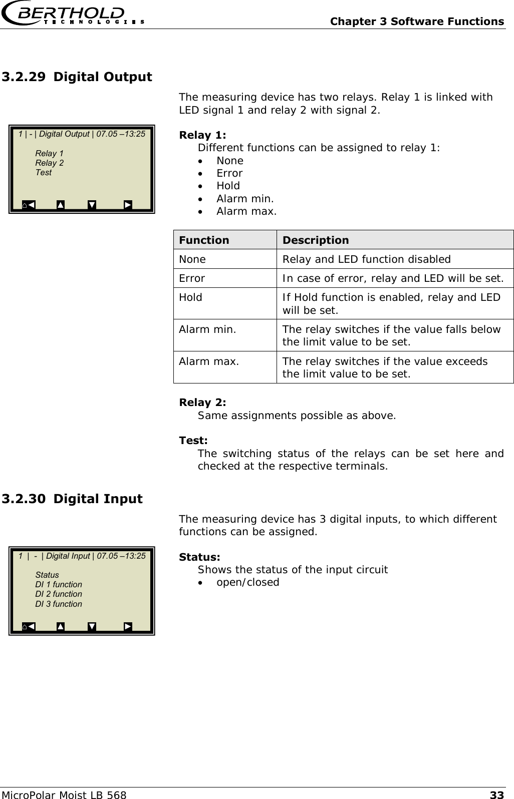
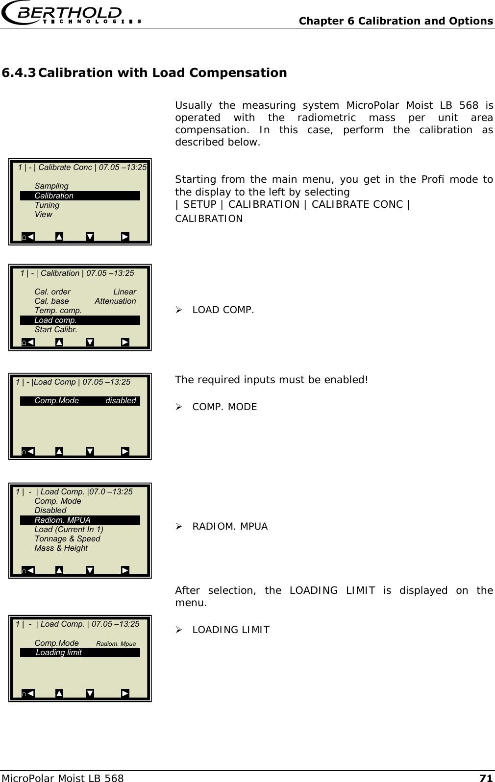
![Chapter 3 System Description MircoPolar Moist LB 568 17 3.3 Loading Compensation The microwave irradiates the product to be measured and detects all changes in the product. Example conveyor belt, see Fig. 3-2: Figure 3-2: Material profile on the conveyor belt The entire material cross-section is transmitted. If the material layer thickness or the bulk density changes (with constant moisture), then the microwave signals will be affected. The goal of the loading compensation is to compensate for this influence. This is done through standardization with regard to the parameters layer thickness and bulk density which correspond to the mass per unit area: Load = mass per unit area [g/cm2] = ∙ d Eq. 3-2 where: bulk density [g/cm3] d material layer thickness [cm] See Eq. 3-1: the standardization is done through division of the phase and attenuation data by the load. A mass per unit area compensation need not be performed when the layer thickness and bulk density are constant in a fixed measuring geometry. This is the case, for example, if conveyor belts are always loaded with the same level, or if the filling level in chutes is always the same, and the material has a constant density. If the loading compensation is not required and not selected, the load is set to 1 (see Eq. 3-1): Load = 1 Loading compensation not enabled](https://usermanual.wiki/Berthold-Technologies/FCC02X03/User-Guide-2774185-Page-17.png)
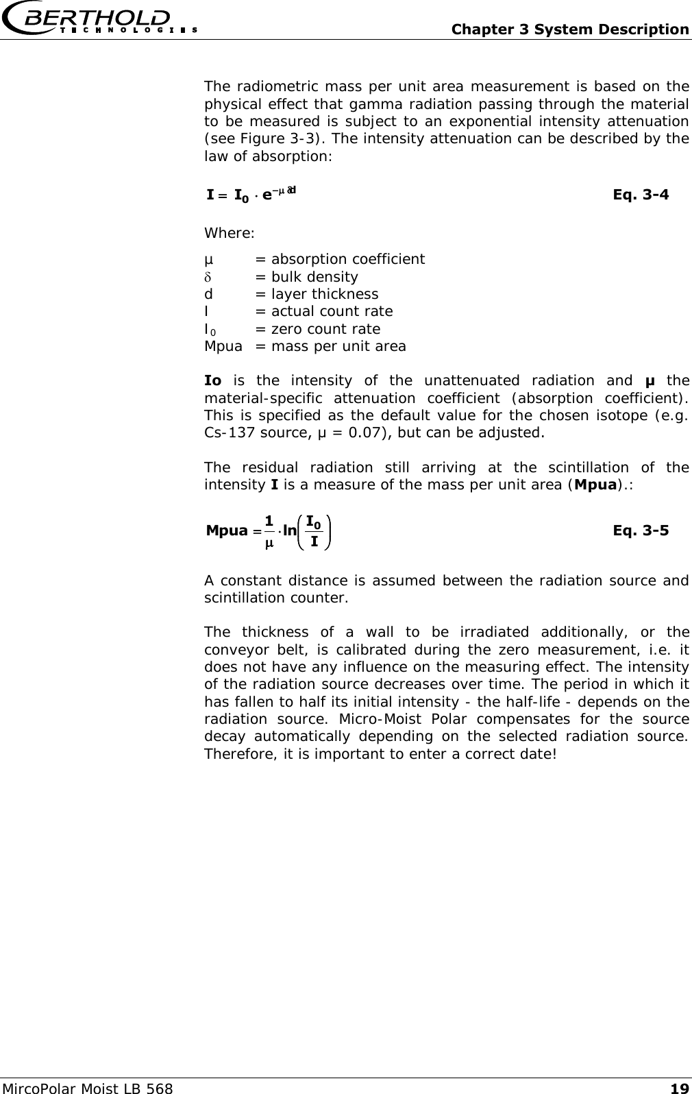
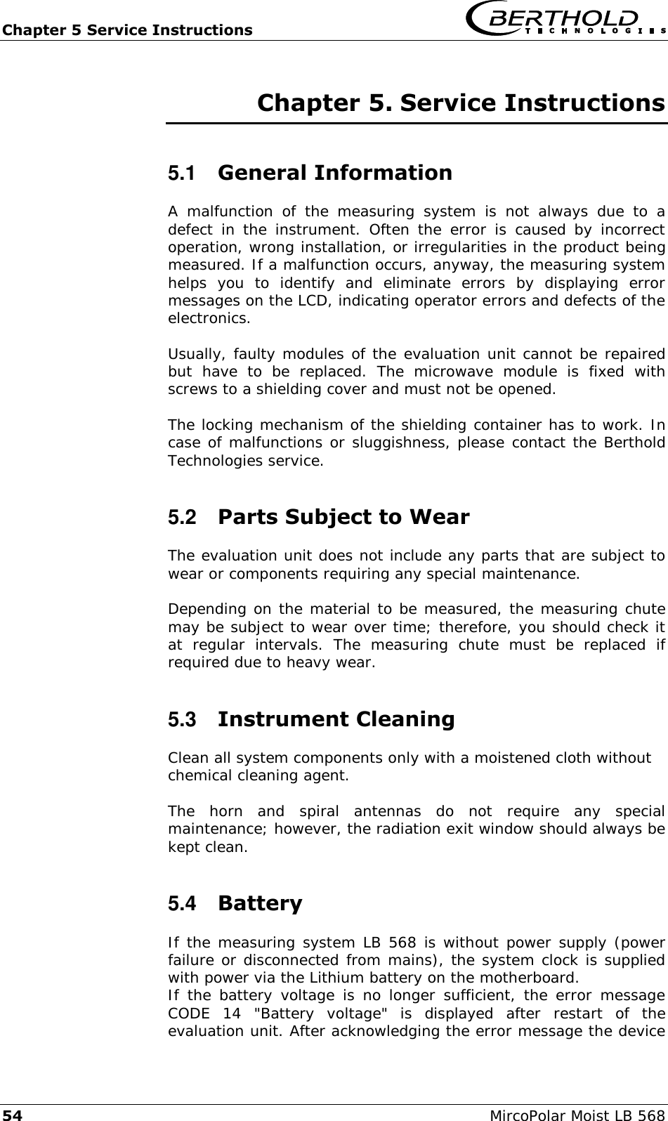
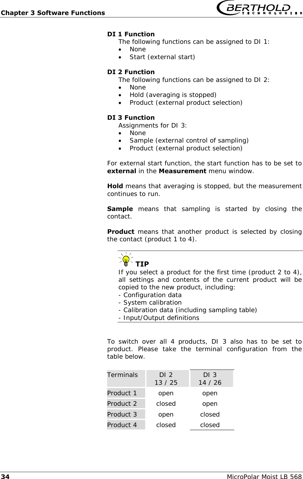
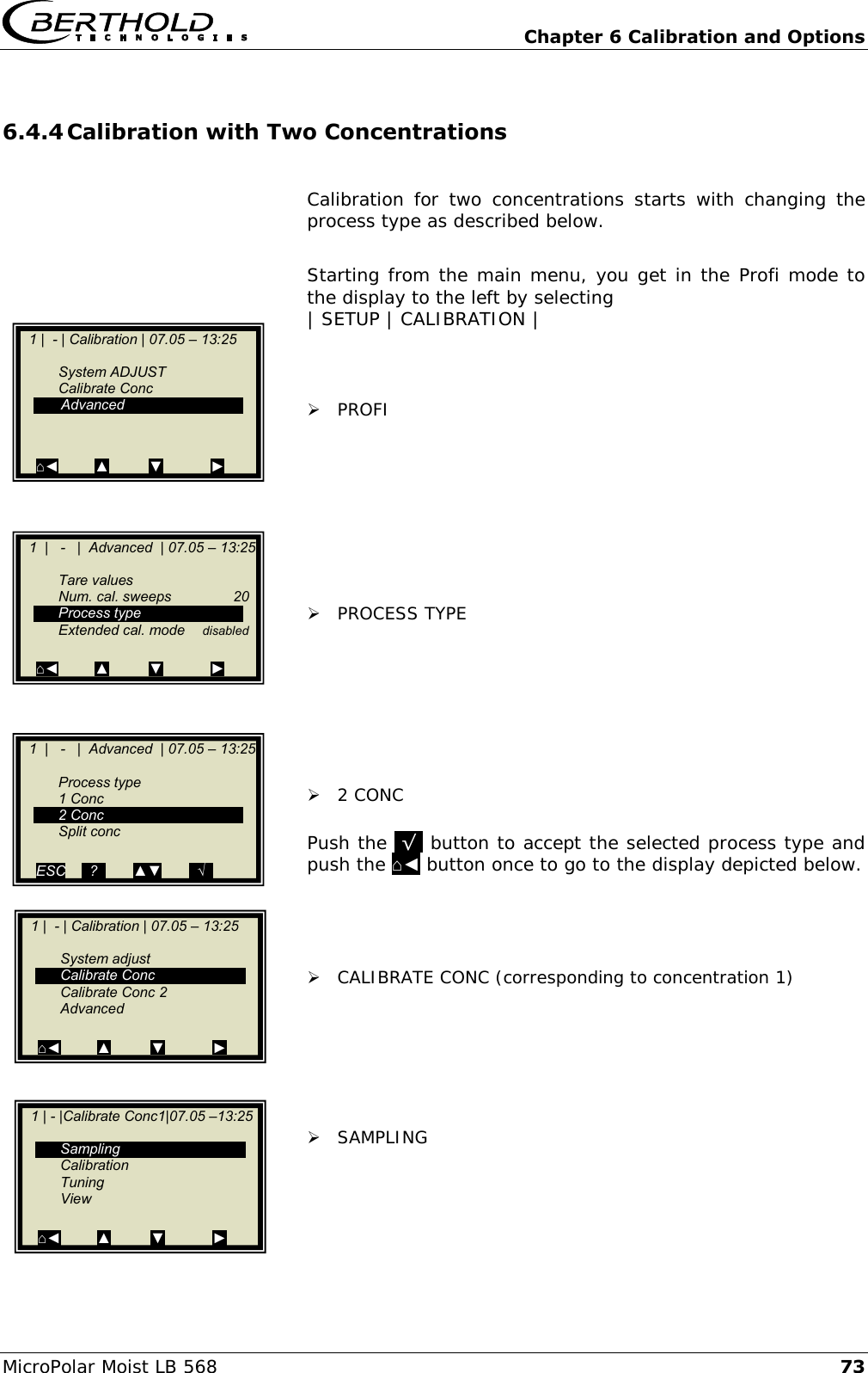
![Chapter 3 System Description 18 MircoPolar Moist LB 568 Depending on the type of load fluctuations, there are several possibilities for compensation; typically, the radiometric mass per unit area compensation is used, which is described below. At constant bulk density or if the mass per unit area is already known, one may not need the radiometric measurement path under certain circumstances. In this case, there are alternative possibilities for compensation, see chapter 7.1 Optional Loading compensation. 3.3.1 Radiometric Mass per Unit Area Compensation The influence of a varying material layer thickness and bulk density disappears through standardization with regard to the irradiated mass per unit area. The compensation is calculated as follows: Load = mass per unit area [g/cm2] Eq. 3-3 The radiometric measurement path supplies the mass per unit area signal. Figure 3-3: Microwaves and gamma radiation field at the conveyor belt](https://usermanual.wiki/Berthold-Technologies/FCC02X03/User-Guide-2774185-Page-18.png)

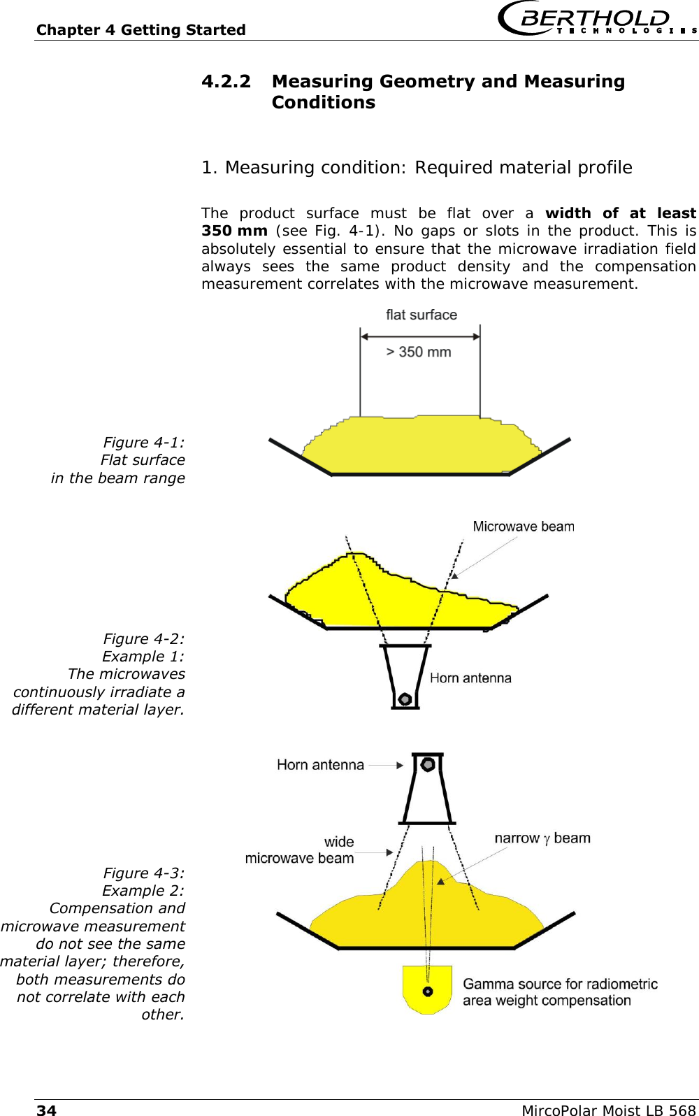
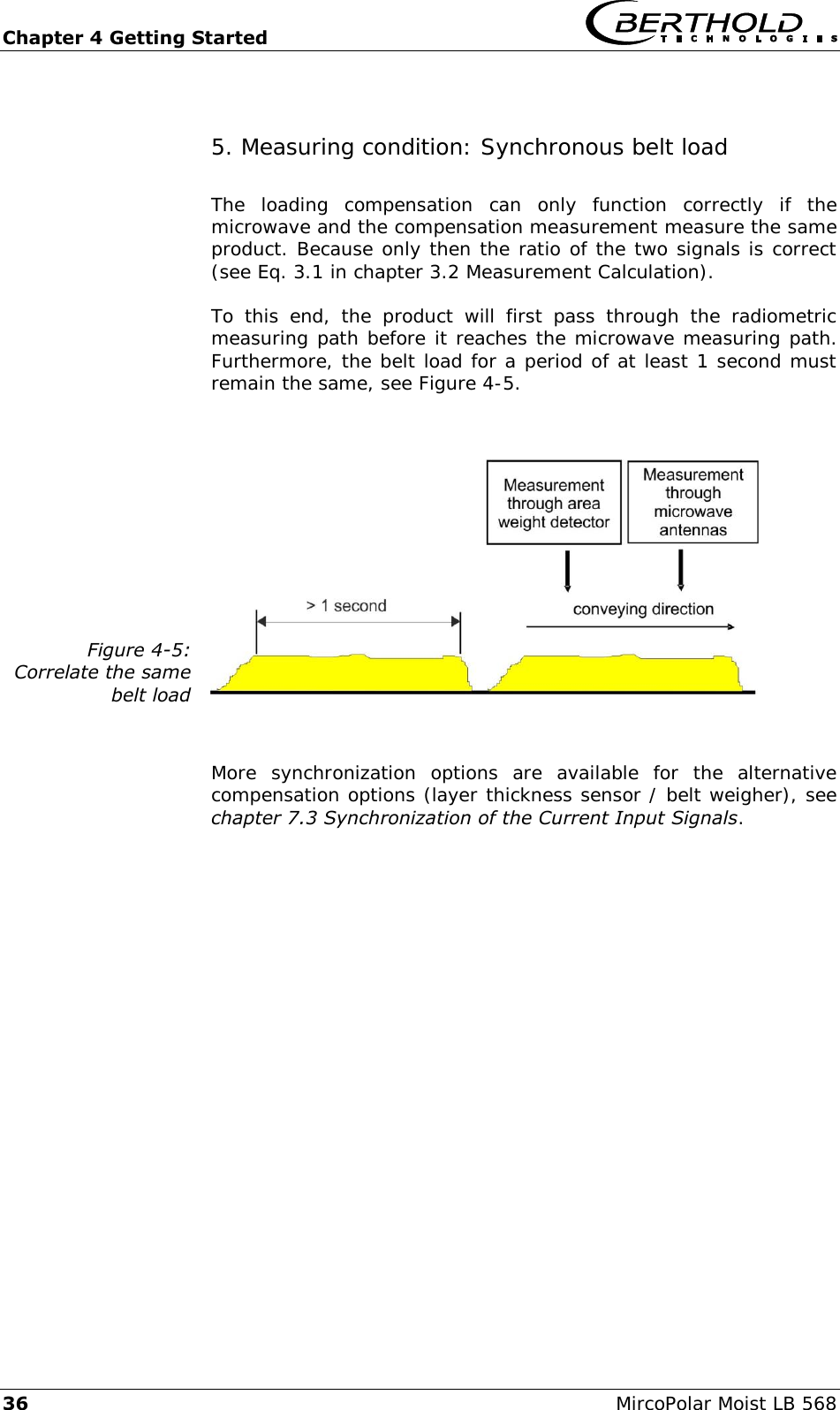
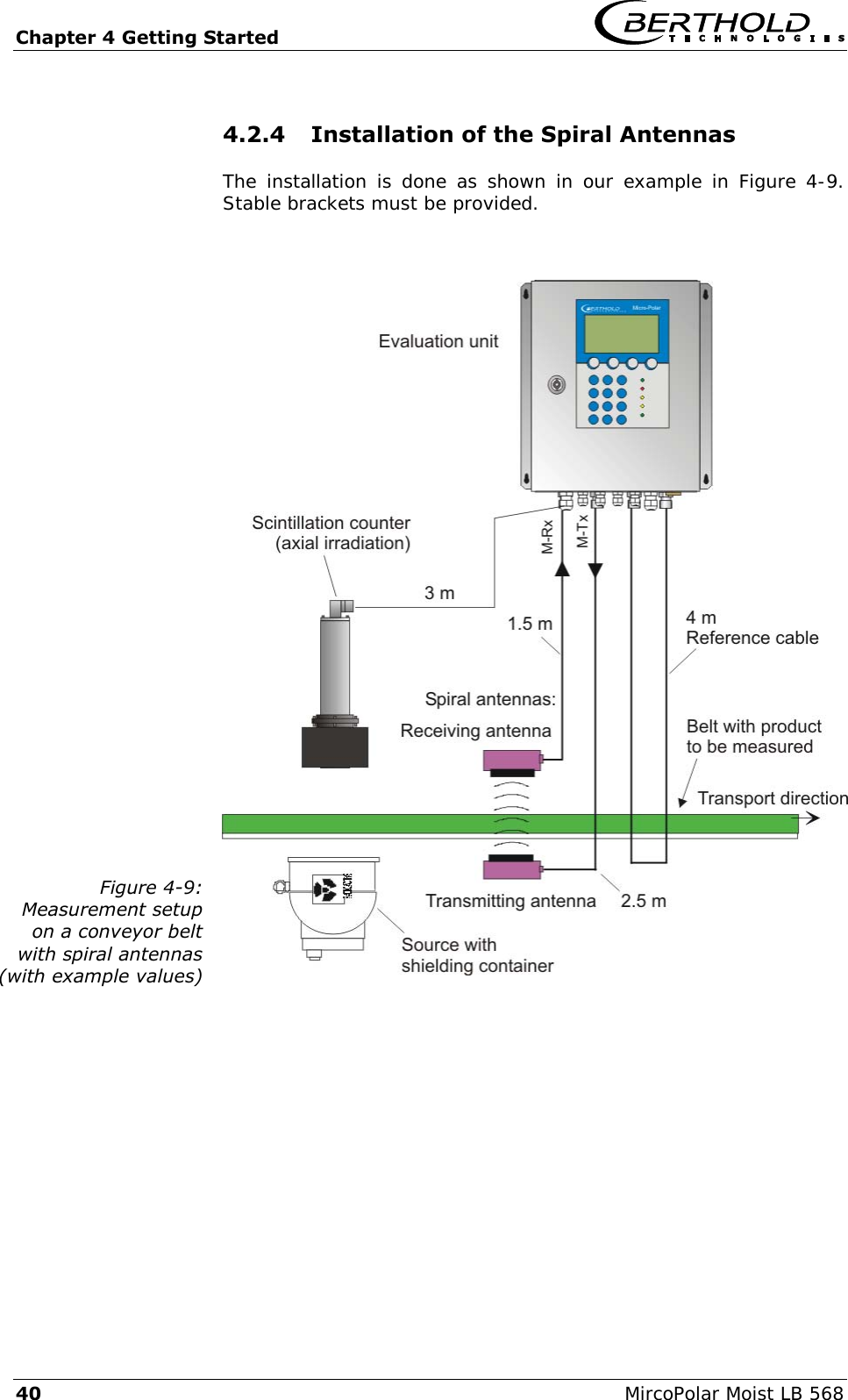
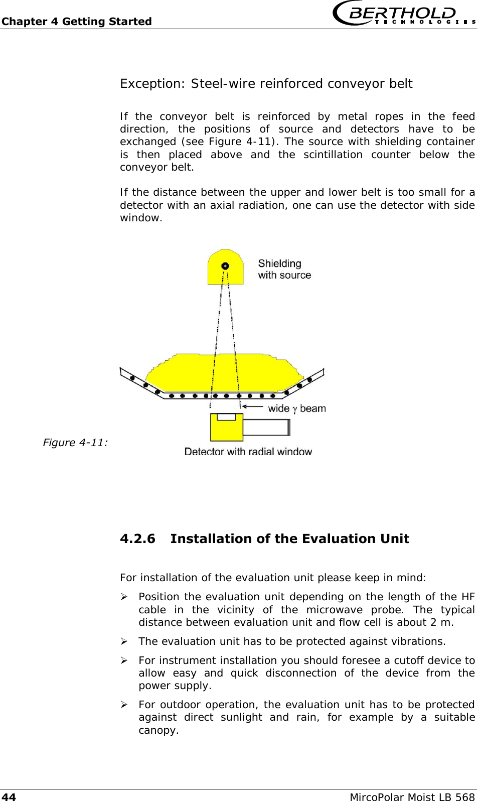
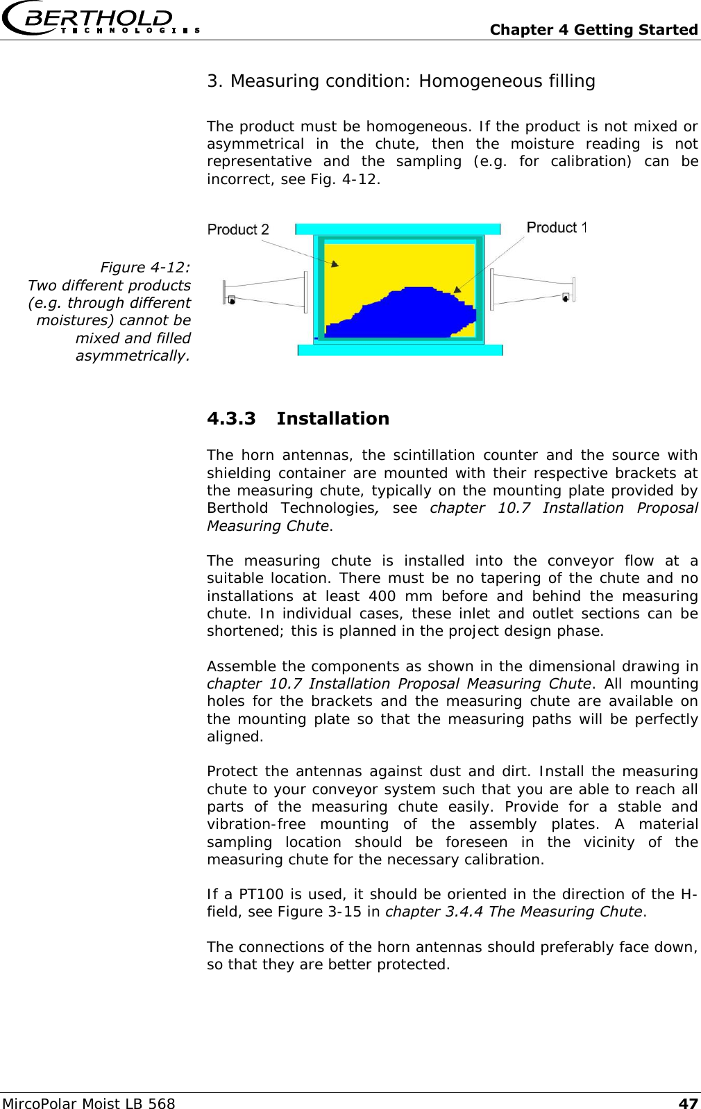
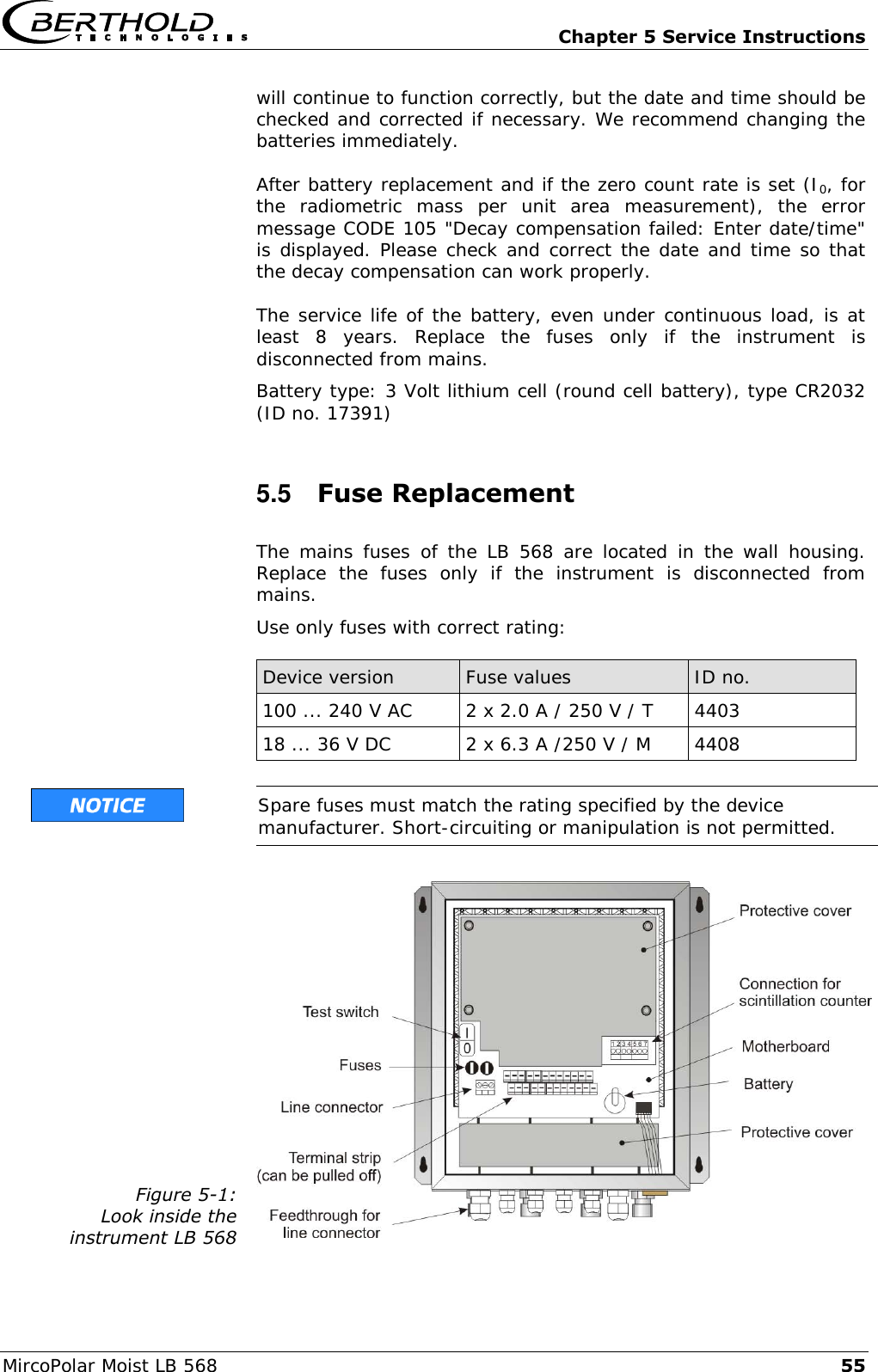
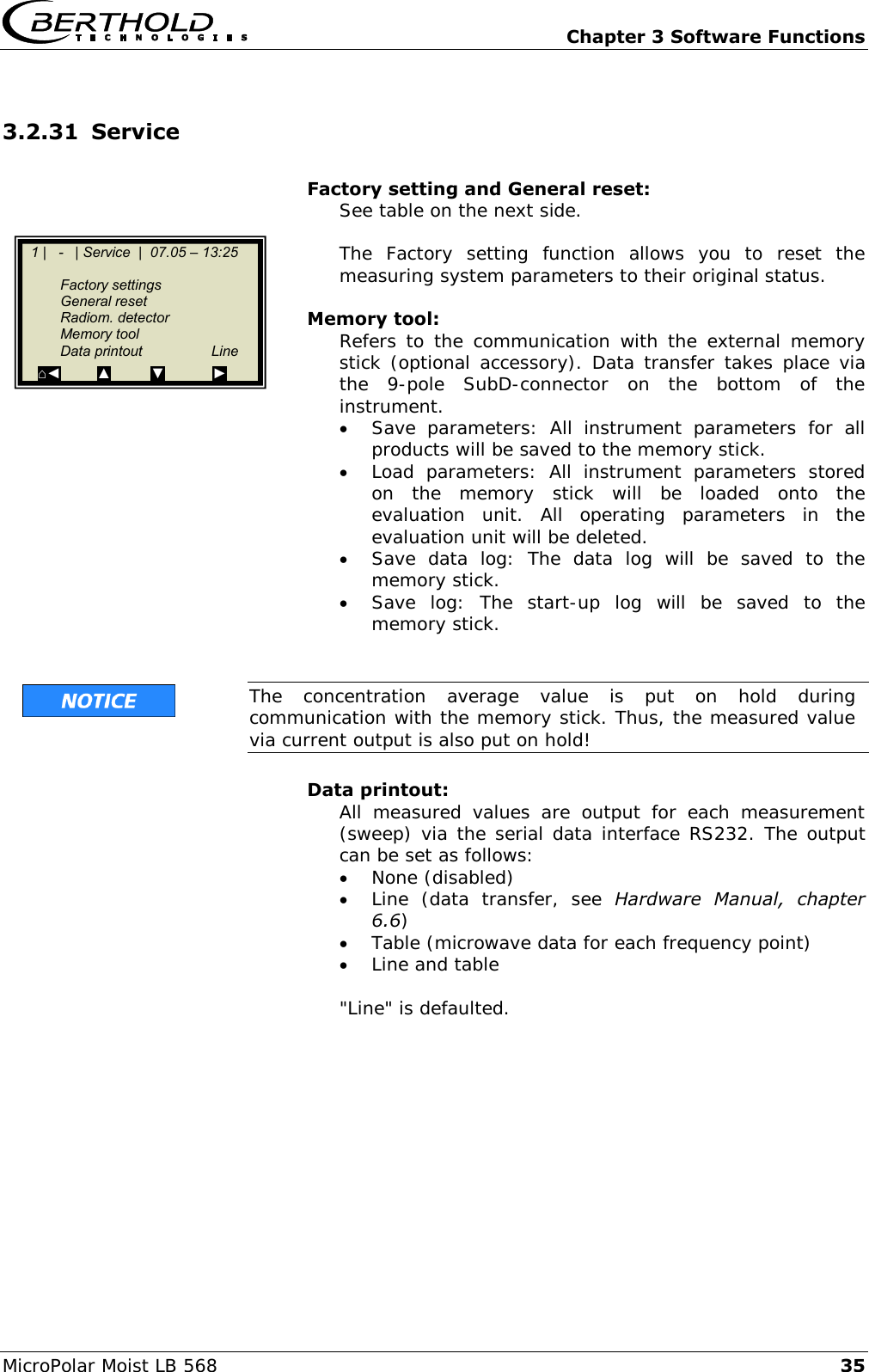
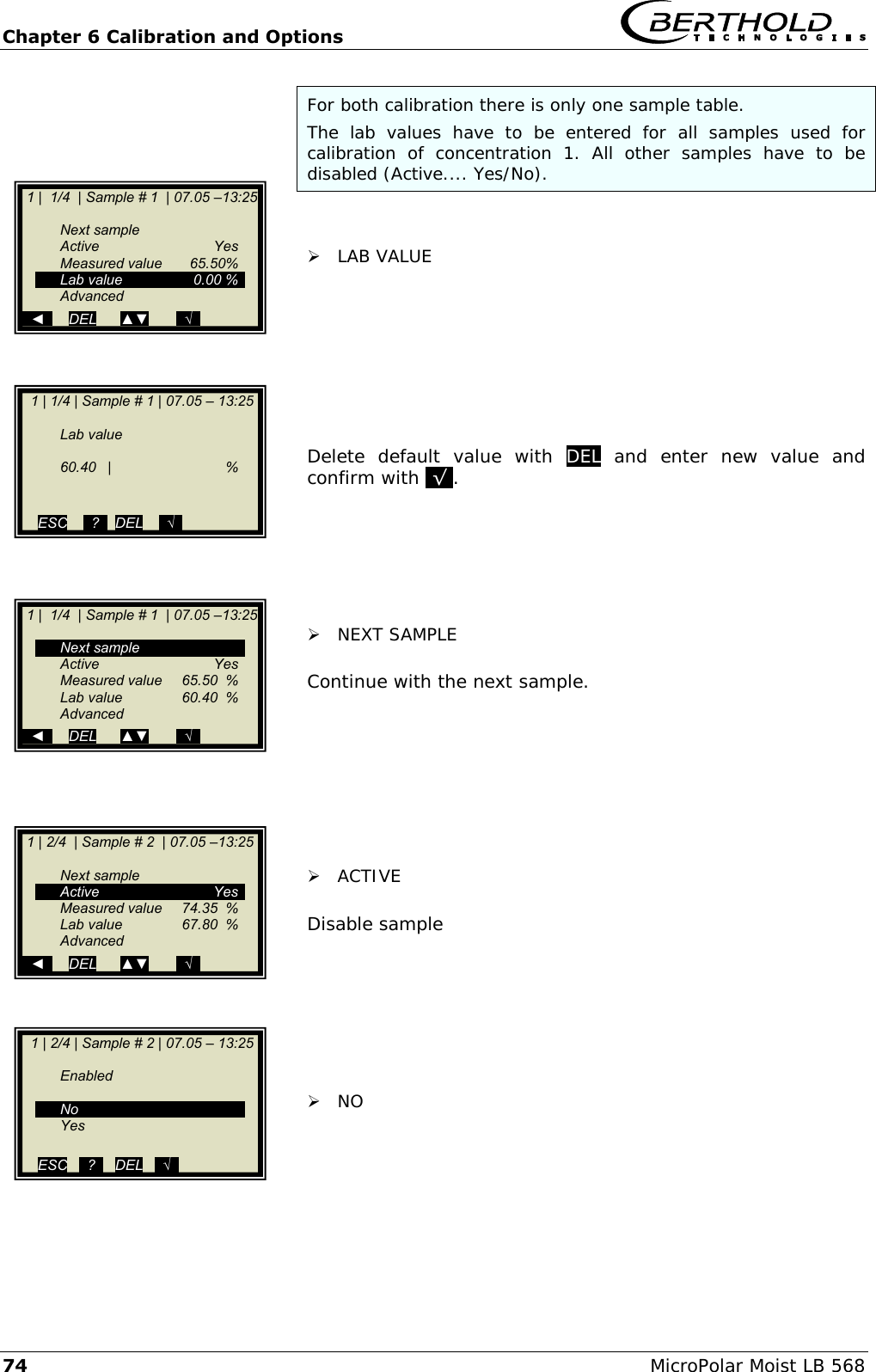
![Chapter 4 Getting Started MircoPolar Moist LB 568 35 2. Measuring condition: Homogeneous load on the belt The product must be homogeneous. If the product is not mixed or asymmetrical on the belt, the moisture reading is not representative and the sampling (e.g. for calibration) may possibly be incorrect, see Fig. 4-4. Figure 4-4: Two different products (e.g. due to different moistures), not mixed and filled asymmetrically. 3. Measuring condition: electrically conductive materials No metals or other conductive materials must be located between transmitting and receiving antennas (in the radiation field). A special case are steel reinforced conveyor belts, see the following chapters. 4. Measuring condition: Minimum load The minimum load on the conveyor belt is dependent on the product composition and the material structure. In a first approximation, the minimum material thickness can be specified as follows: 4min d Eq. 4-1 Where: dmin = minimum material thickness [cm] = bulk density [g/cm3]](https://usermanual.wiki/Berthold-Technologies/FCC02X03/User-Guide-2774185-Page-35.png)

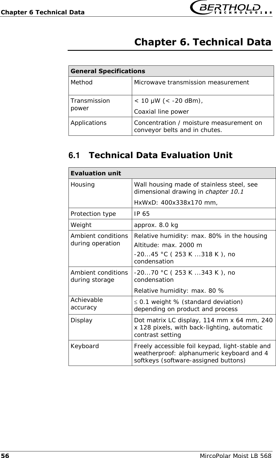
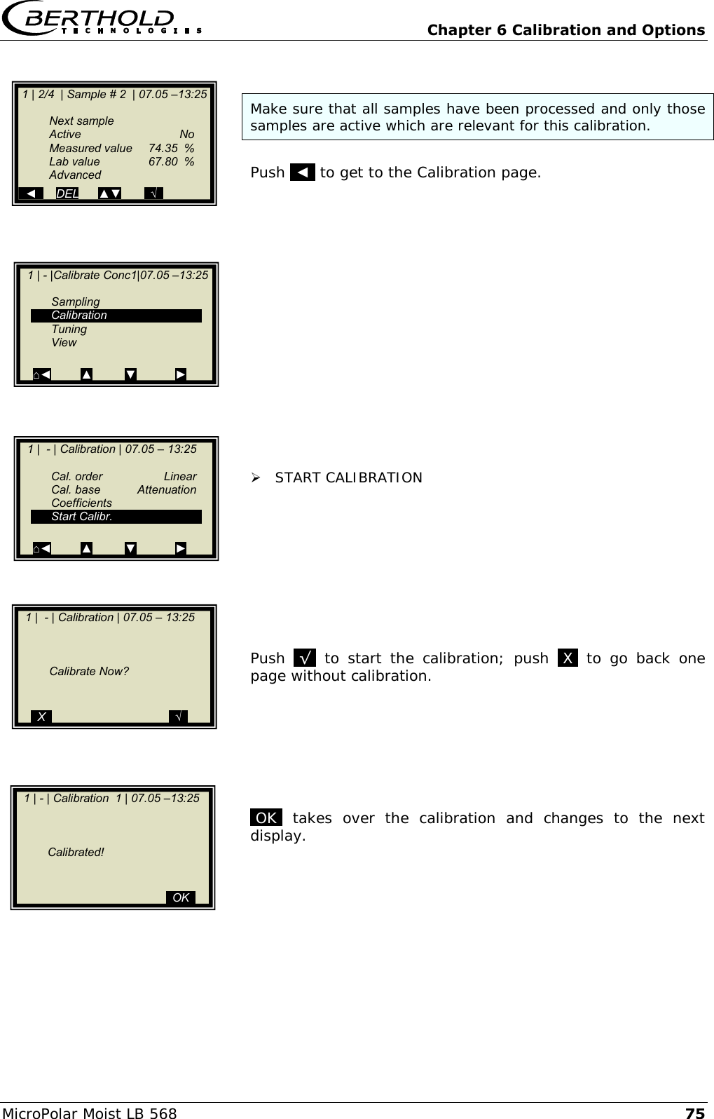
![Chapter 6 Technical Data MircoPolar Moist LB 568 63 6.5 Technical Data HF-Cable HF cable Material Cable sheath: Polyethylene (PE) Protection type IP 68 in the screwed on state Temperature Operating temperature: -40...85 °C Installation temperature: -40...85 °C Installation temperature: -40...85 °C Attenuation load approx. 0.3 dB / m Cable length [m] ID no. 0.5 11473 1.0 11474 1.5 11475 2.0 11476 2.5 11477 3.0 11478 3.5 11479 4.0 11480](https://usermanual.wiki/Berthold-Technologies/FCC02X03/User-Guide-2774185-Page-63.png)
![Chapter 6 Technical Data 64 MircoPolar Moist LB 568 6.6 Serial Data Output RS232 Format Headline Date·TimeStateStatusDetectorStatusSynchronizerProductAttPhiPhi(f=0) R2CorrTintIN1IN2Pt100CCmC2C2mCpsMDetTempMpua¶ Following lines 01.01.2005·00:00:00000000510.435.303.11 1 2 3 4 5 6 7 8 9 0.070.980.00.00.00.075.3675.000.000.00365335.810.25¶ 10 11 12 13 14 15 16 17 18 19 20 21 22 Column no. Description Format 1 Date and time DD.MM.YY·HH:MM:SS 2 State 4 digits, HEX 3 Status: Information on the quality of the last measurement 0 : Measurement OK < 0 : Error 4 Detector status: Information on the quality of the last measurement 0 : Measurement OK < 0 : Error 5 Product synchronization 5 : not active 1: still asynchronous 0: all values synchronous -1: Error -2: Time to short for syn. -3: Speed outside range 6 Product number X (1 to 4) 7 Attenuation [dB] X.XX 8 Phase [°/GHz] X.XX 9 Phase offset (phase at frequency = 0 Hz) X.XX 10 Dispersion of the phase regression X.XX 11 Correlation of the phase regression X.XX 12 Device temperature [temperature unit] X.X 13 Current input 1 [unit of current input] X.X 14 Current input 2 [unit of current input] X.X 15 PT100 temperature [temperature unit] X.X](https://usermanual.wiki/Berthold-Technologies/FCC02X03/User-Guide-2774185-Page-64.png)
![Chapter 6 Technical Data MircoPolar Moist LB 568 65 16 Concentration 1 live X.XX 17 Concentration 1 averaged X.XX 18 Concentration 2 live X.XX 19 Concentration 2 averaged X.XX 20 Averaged count rate [counts/s] X 21 Detector temperature [°C] X.X 22 Mass per unit area [g/cm2] X.XX Special characters “” Tabulation “¶” Carriage return + Line feed “·” Blank characters](https://usermanual.wiki/Berthold-Technologies/FCC02X03/User-Guide-2774185-Page-65.png)
![Chapter 7 Other Compensation Options 66 MircoPolar Moist LB 568 Chapter 7. Other Compensation Options 7.1 Optional Loading Compensation At constant bulk density or if the mass per unit area is already known, one may not need the radiometric measurement path under certain circumstances. In this case, there are alternative compensation options, see the following chapter. 7.1.1 Mass per Unit Area Compensation The influence of a varying material layer thickness and bulk density disappears through standardization with regard to the irradiated mass per unit area. The compensation is calculated as follows: Load = mass per unit area [g/cm2] Eq. 7-1 The mass per unit area signal supplies a 0(4)...20 mA signal. IMPORTANT Current input 1 must be used for this mass per unit area compensation via an external current signal. 7.1.2 Layer Thickness Compensation If only the layer thickness of the product to be measured changes, one has to compensate as follows: Load = Loading level [cm] Eq. 7-2 The layer thickness supplies a 0(4)...20 mA signal which is proportional to the distance from the product surface to a sensor installed above it. IMPORTANT Current input 1 must be used for this compensation.](https://usermanual.wiki/Berthold-Technologies/FCC02X03/User-Guide-2774185-Page-66.png)
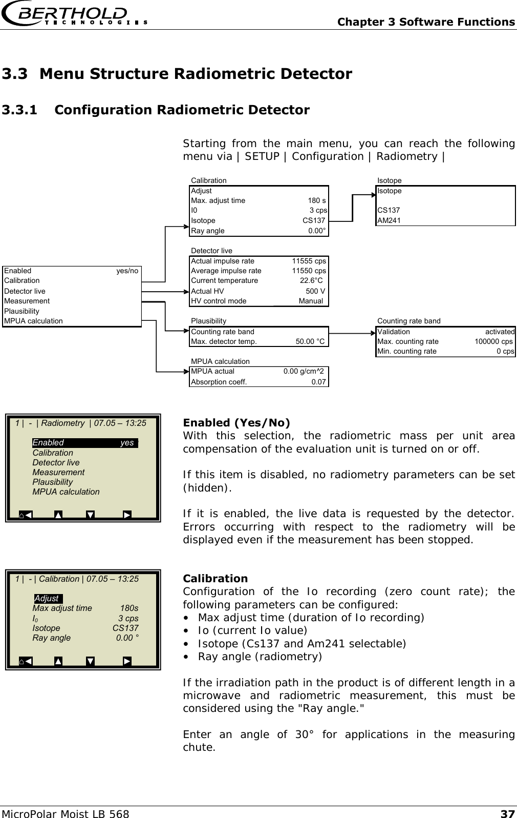
![Chapter 7 Other Compensation Options MircoPolar Moist LB 568 67 7.1.3 Weight/Throughput Compensation If the material cross-section is rectangular (see Fig. 7-1), the mass per unit area [g/cm²] is proportional to the weight per length [kg/m]. Thus, the loading compensation becomes linear; it is calculated as follows: Load = Weight [kg] Eq. 7-3 The 0(4)...20 mA signal is supplied by an existing weighing system. If the weighing system supplies a throughput signal (T/h), either the conveyor belt speed must be constant, or the belt speed must be fed as 0(4)…20 mA signal into the evaluation unit via the second current input. The compensation is then calculated according to: ]s/m[ speed Belt]h/T[ ThroughputLoad Eq. 7-4 IMPORTANT The throughput signal must be fed in via current input 1 and the speed signal via current input 2. Figure 7-1: Rectangular material cross-section with weighing system](https://usermanual.wiki/Berthold-Technologies/FCC02X03/User-Guide-2774185-Page-67.png)
![Chapter 7 Other Compensation Options 68 MircoPolar Moist LB 568 7.1.4 Layer Thickness and Weight Compensation The compensation of weight and layer height can be combined. Prerequisite is a rectangular material cross-section, as described in chapter 7.1.3. The compensation is then calculated according to: Load = layer thickness [cm] x weight [kg] Eq. 7-5 The layer thickness and the weight supply a 0(4)...20 mA signal each. The compensation signal of the weighing station can be used as throughput signal only if the speed is constant. Varying belt speeds cannot be taken into consideration. IMPORTANT The weight signal must be fed in via current input 1 and the layer thickness signal via current input 2.](https://usermanual.wiki/Berthold-Technologies/FCC02X03/User-Guide-2774185-Page-68.png)
![Chapter 7 Other Compensation Options 70 MircoPolar Moist LB 568 7.3 Synchronization of the Current Input Signals The LB 568 offers the option to synchronize the current input signals with the microwave information. The current input signals are stored temporarily. This function is helpful, for example, if the weighing system (z. B. belt weigher) is located in a certain distance from the microwave measuring path. By means of the synchronization, both measurements can be correlated with each other, so that both measurement information come from the same product. If a weight/throughput signal for loading compensation will be used and if the weighing system is more than 5 m away from the microwave measuring path, then - depending on the belt speed - the weight/throughput signal has to be synchronized with the microwave information so that both signals measure the same product. The minimum distance is: 5 x v Eq. 7-8 Where: v = belt speed [m/s] The permissible maximum distance of both measuring devices depends on the belt speed and is calculated as follows: Belt speed [m/s] Maximum distance [m] < 1 50 > 1 100 Min. distance Max. distance](https://usermanual.wiki/Berthold-Technologies/FCC02X03/User-Guide-2774185-Page-70.png)


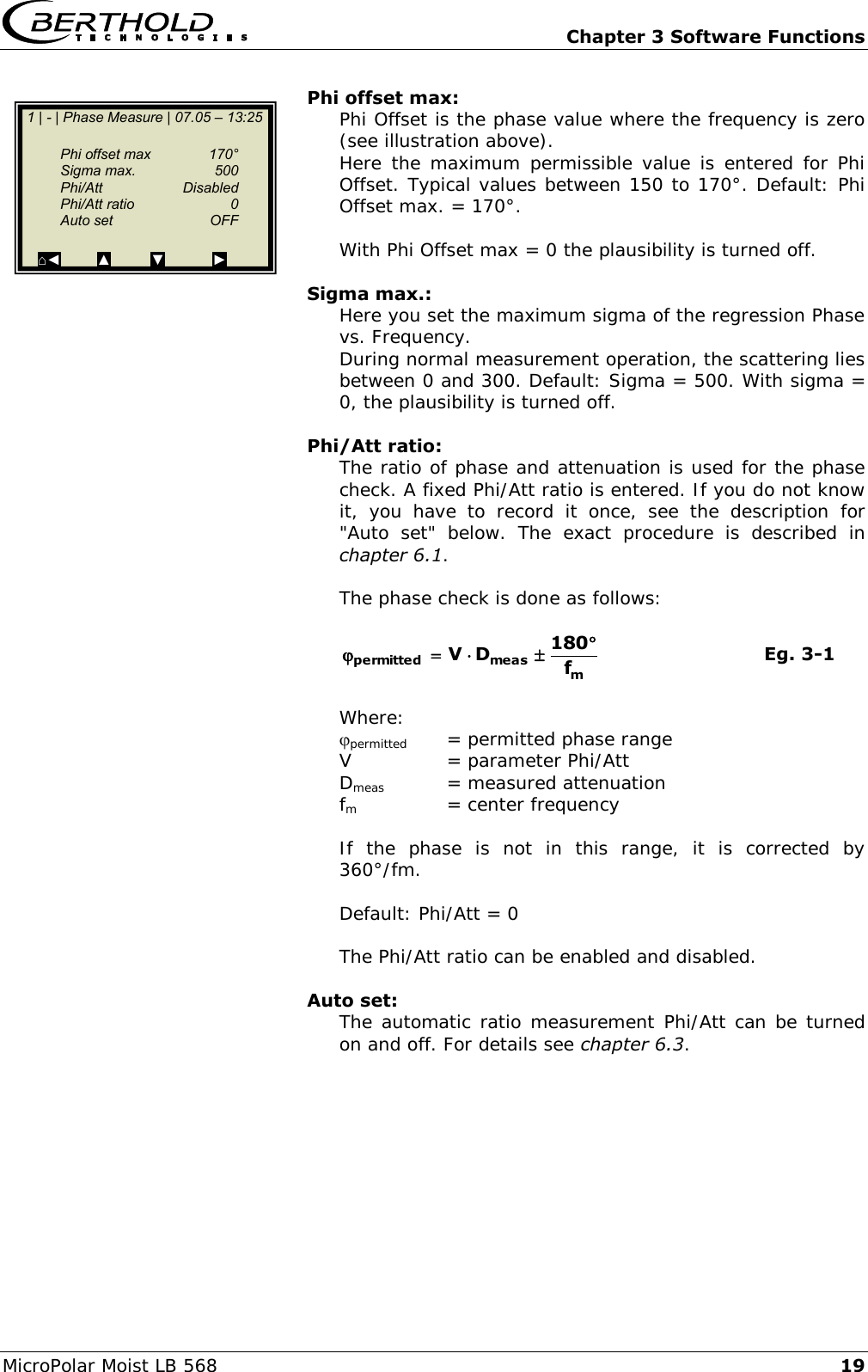
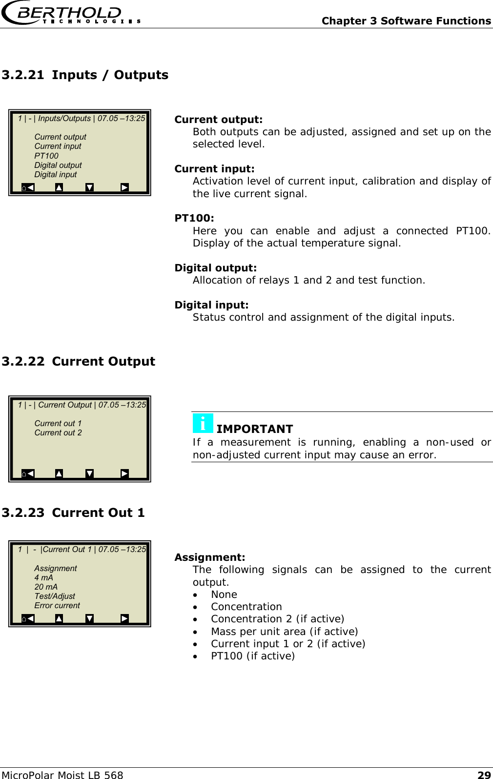
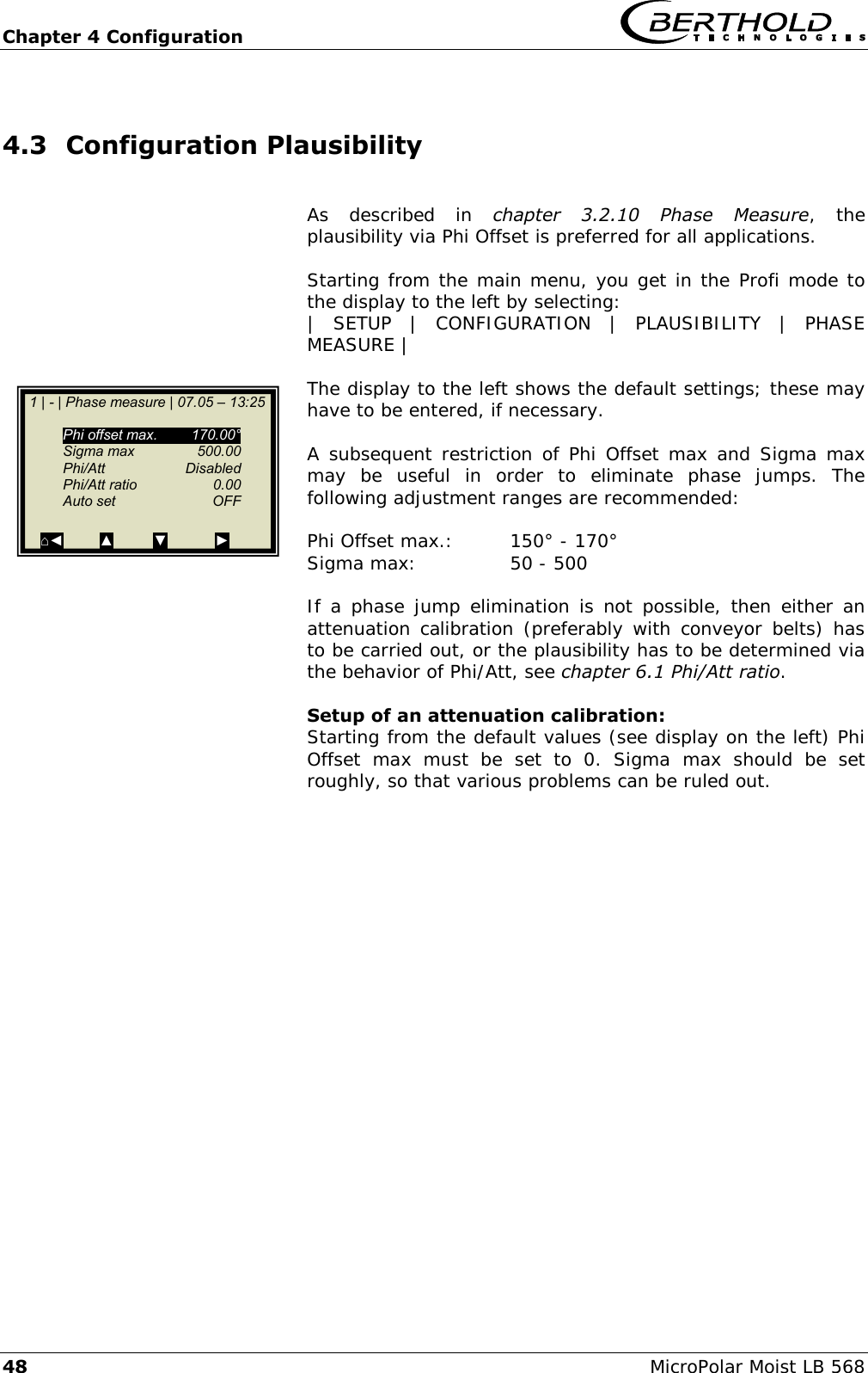
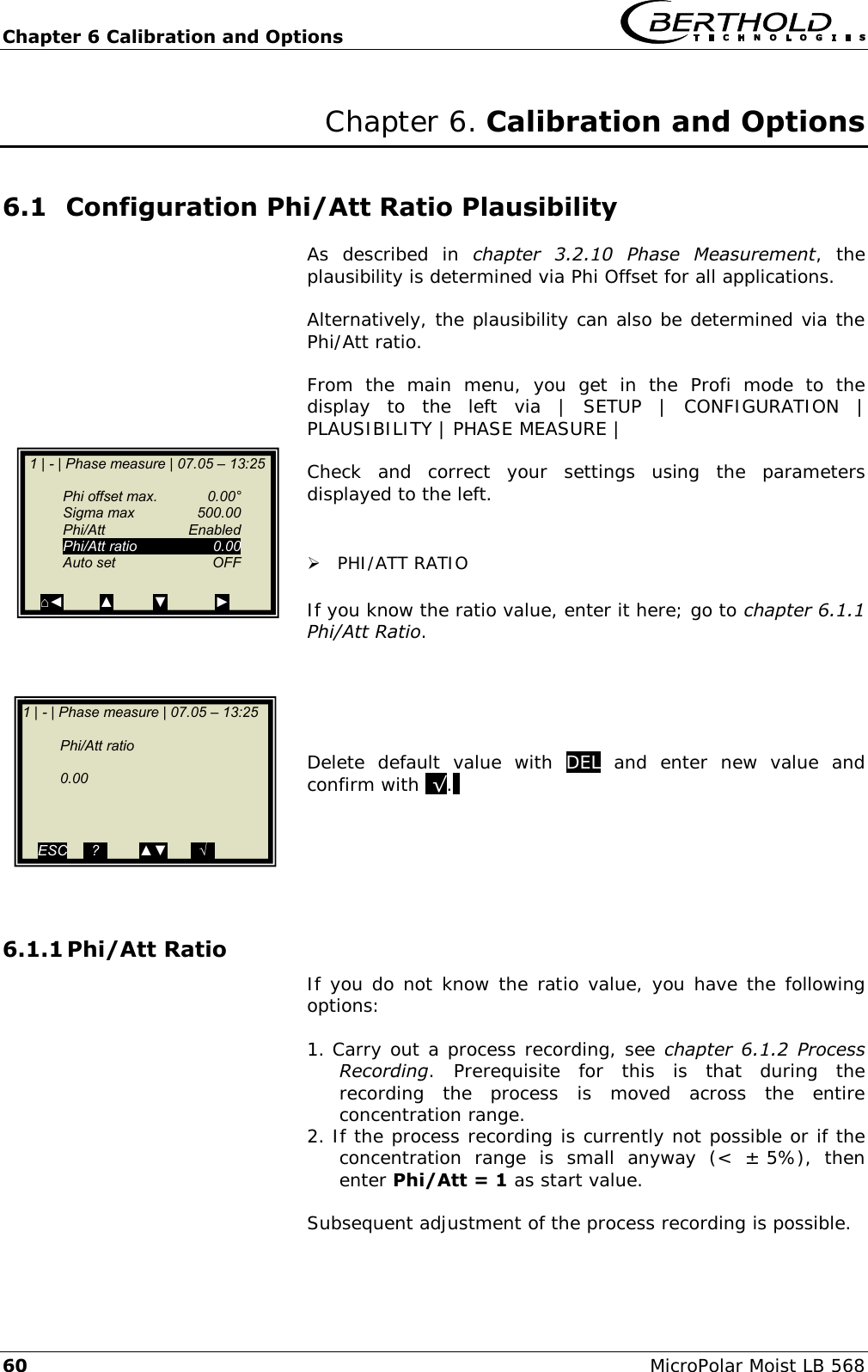
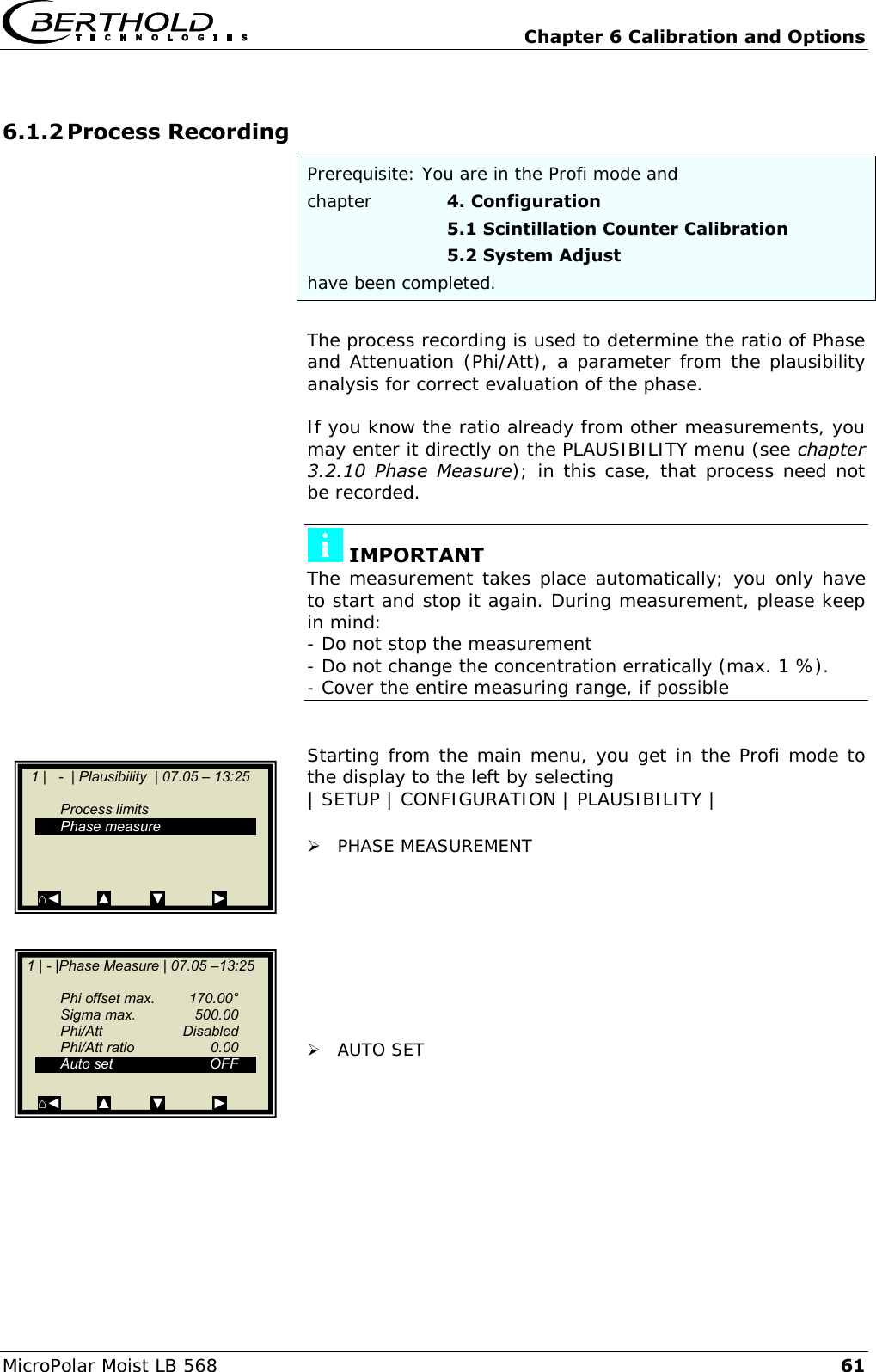
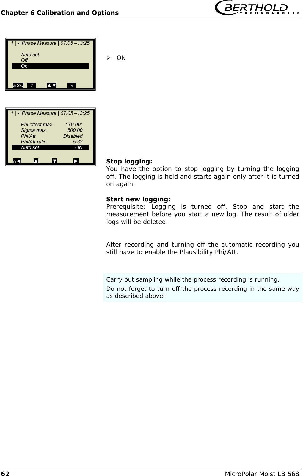
![Chapter 3 Software Functions 18 MicroPolar Moist LB 568 3.2.10 Phase Measure The phase and attenuation are calculated for each measured value (measuring cycle) from a multitude of single measurements of different frequencies in a wide frequency band (called sweep/frequency sweep). Such a measurement permits a continuous verification of the plausibility of the results of a measurement. The size of the frequency range allows you to select a belt to possibly rule out strong interferences (for example due to reflection) from the start. The frequency selection is done manually on the menu | SETUP | CONFIGURATION | MICROWAVE. As a rule, the frequency band "Standard" (this is the factory setting) is a good choice. The attenuation calculation takes place through averaging via the frequency range, without further plausibility check. The phase calculation takes place through regression calculation via the frequency range, followed by a plausibility check (see the illustration below). Phase [DEG]Frequency [GHz]fStart fmRegression lineFrequency pointsPhi OffsetPhi(f=fm) The phase check is always done through Sigma max and a second selectable plausibility of Phi Offset max or Phi/Att ratio. A combination of Phi Offset and Phi/Att ratio is not possible. If Sigma max or Phi Offset max is exceeded, then the measurement is rejected. If the exceeding occurs continuously exceeded, the evaluation unit changes to the error state. The time up to when the fault is triggered is 75% of the averaging time of the mean concentration value. In the factory state, the plausibility is adjusted via Phi Offset; this is recommended for all applications.](https://usermanual.wiki/Berthold-Technologies/FCC02X03/User-Guide-2774185-Page-109.png)
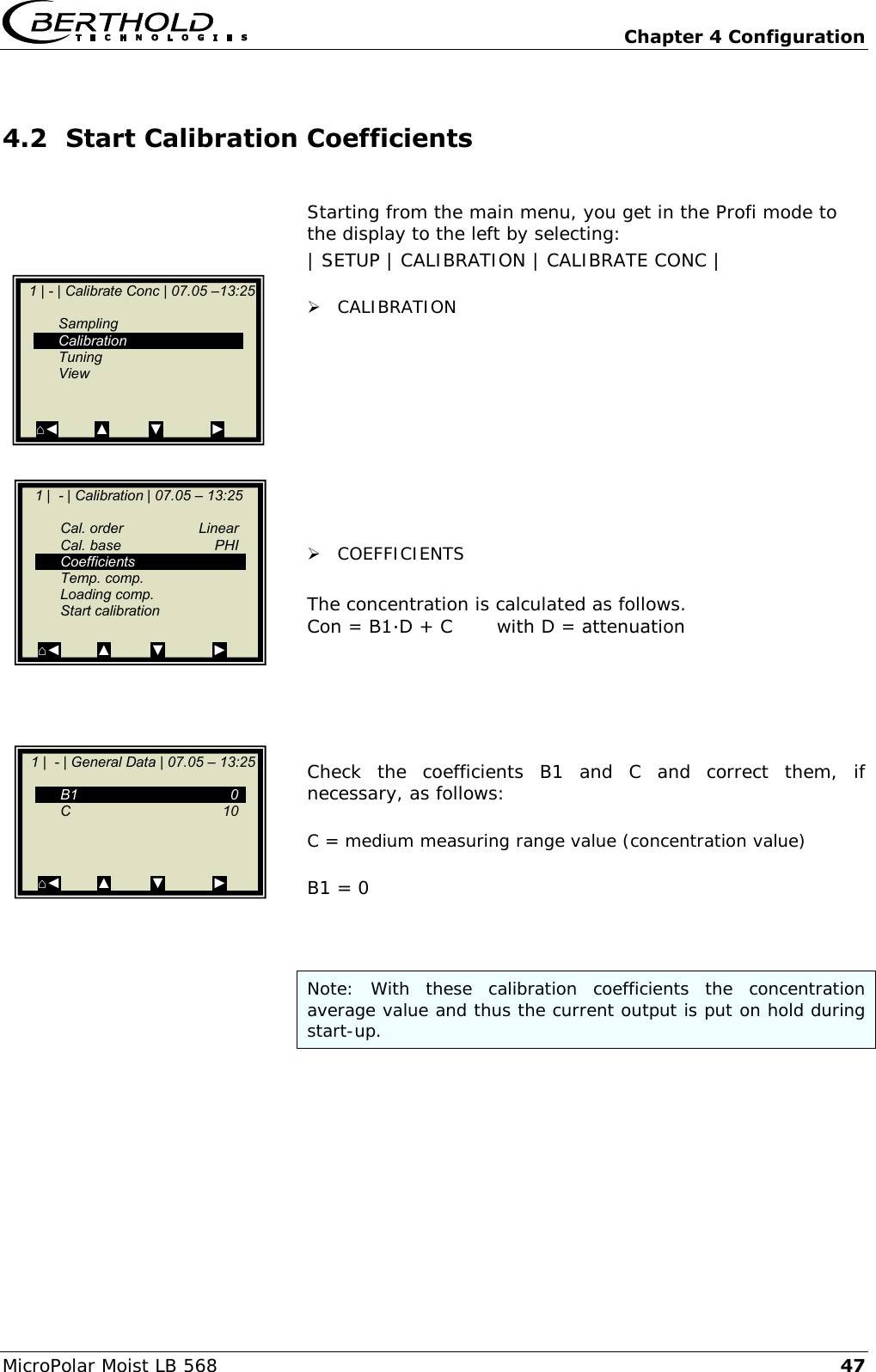
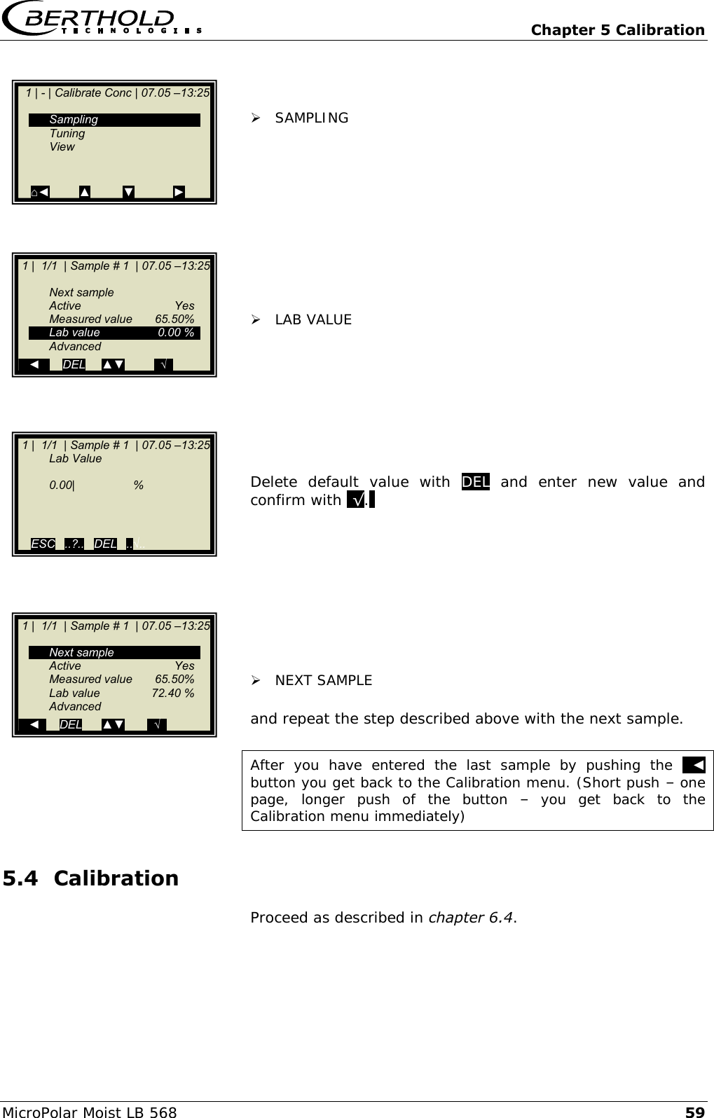
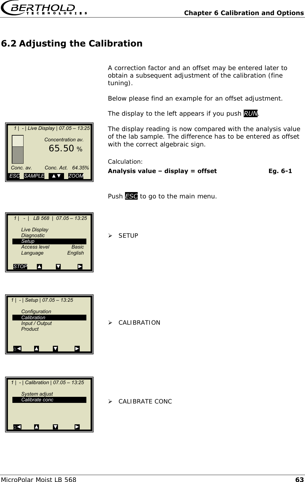
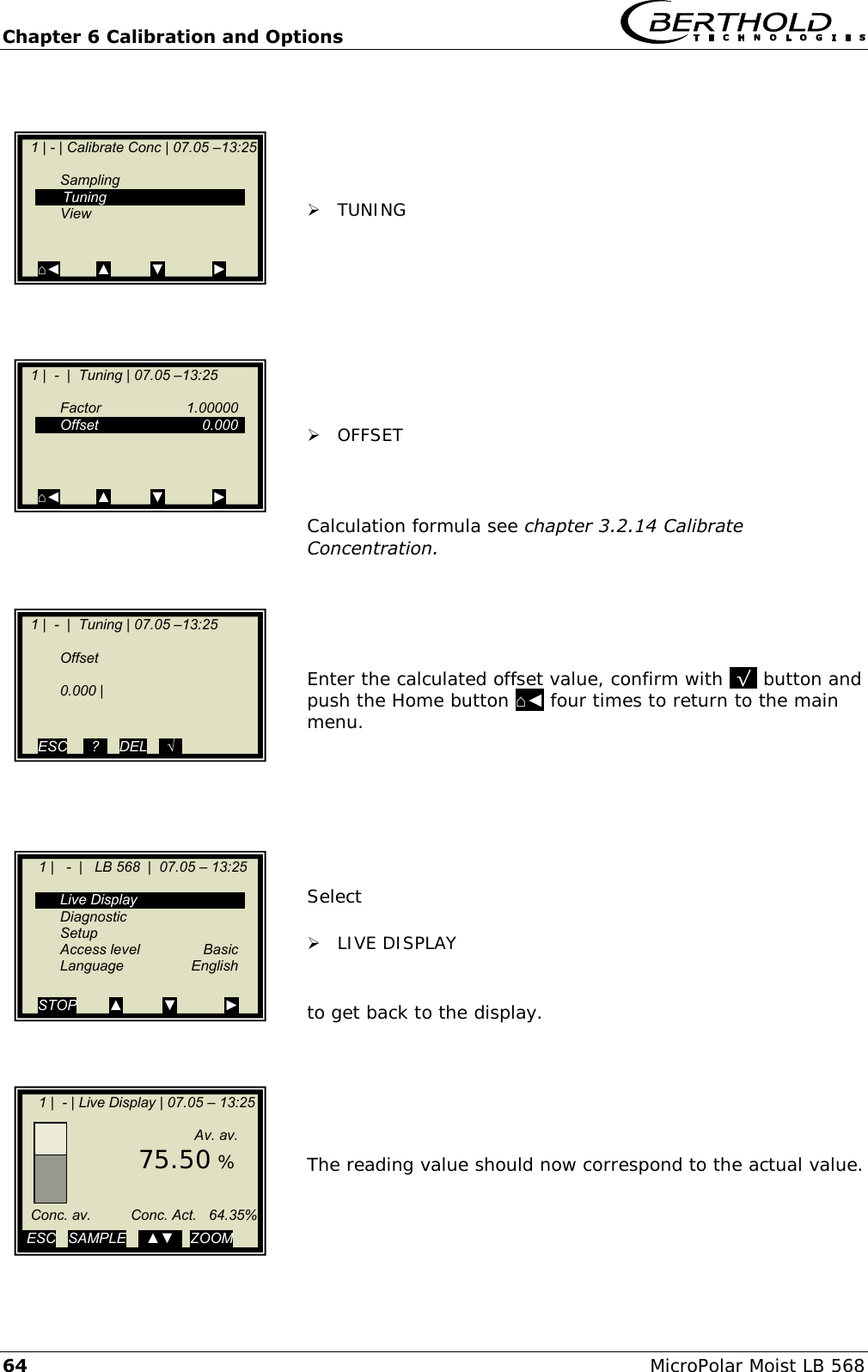
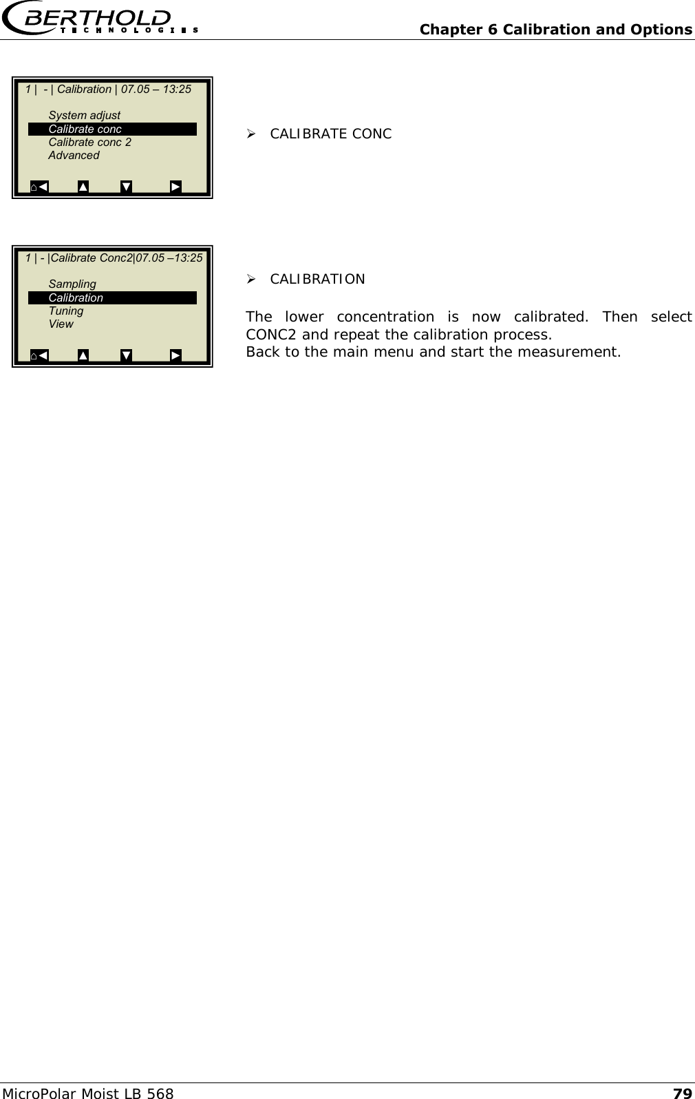
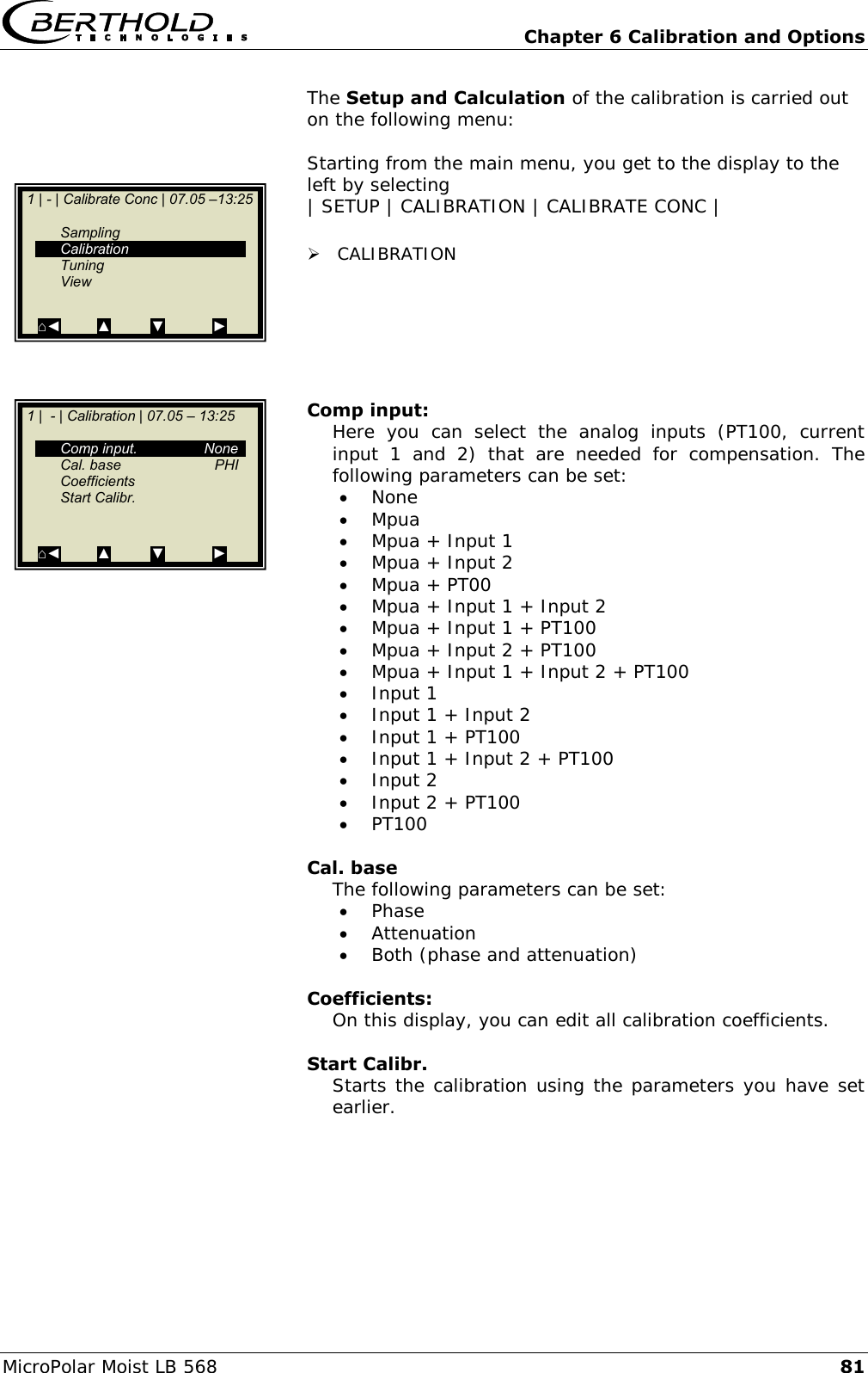
![Chapter 3 Software Functions 22 MicroPolar Moist LB 568 3.2.14 Calibrate Concentration Sampling: Shows all measured samples and entered lab values. Calibration: Here you can choose the calibration order [linear/quadratic], the basis [phase/attenuation or both] and the compensations. For details please see chapter 3.2.18 Calibration. Select Calibration to enable and parameterize the temperature and loading compensation. Select Calibration to carry out the automatic calculation of the coefficients. Tuning: Subsequent correction of the reading is possible by entering a factor and an offset. Calculation is carried out using the following formula: OffsetFactorDisplay display Corrected Eg. 3-2 View: Presentation of calibration curve, display of correlation and coefficients. 1 | - | Calibrate Conc | 07.05 –13:25 Sampling Calibration Tuning View ⌂◄ ▲ ▼ ►](https://usermanual.wiki/Berthold-Technologies/FCC02X03/User-Guide-2774185-Page-113.png)
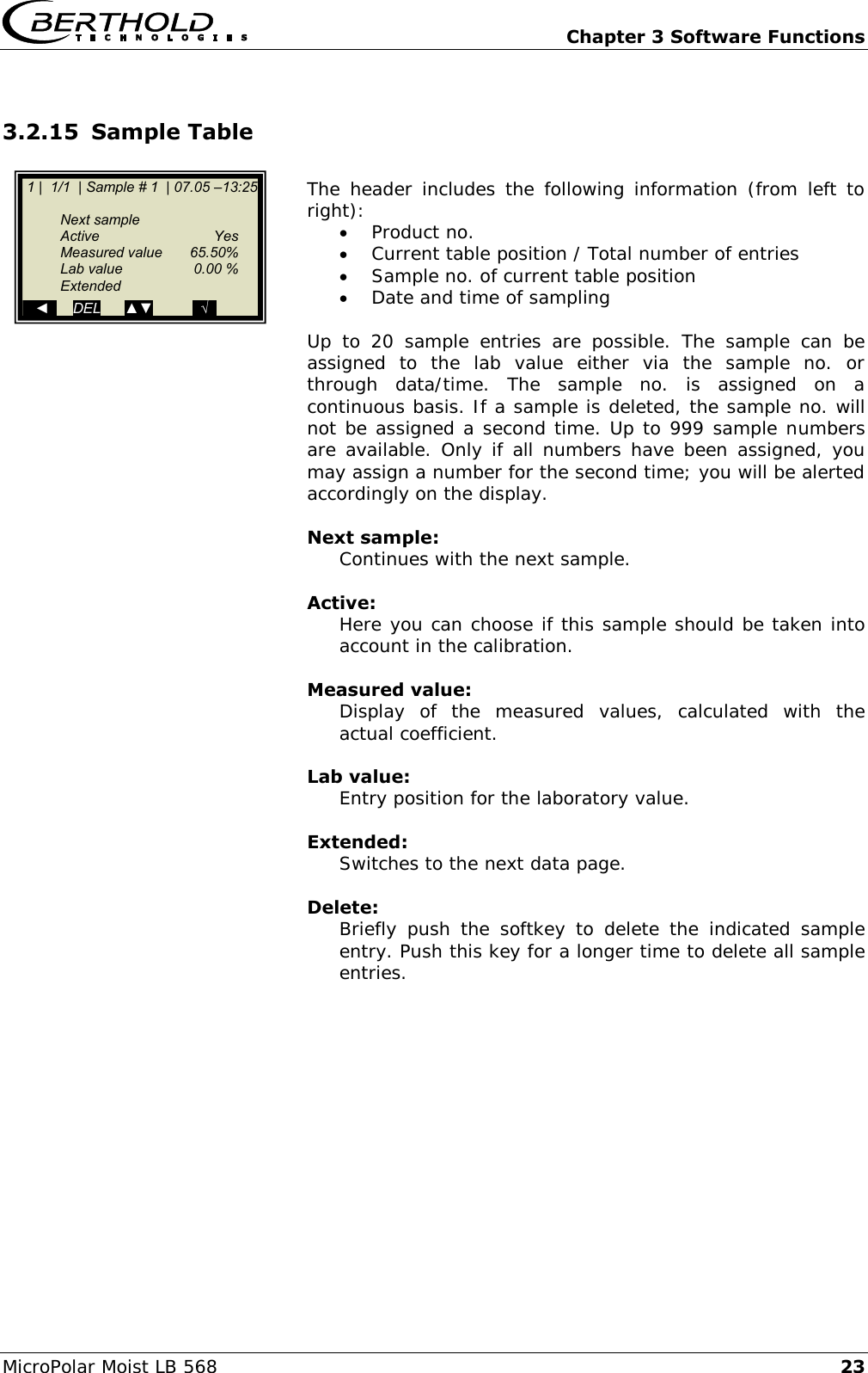
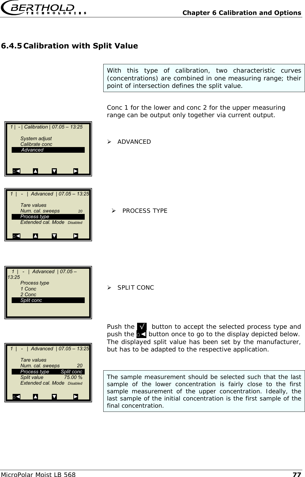
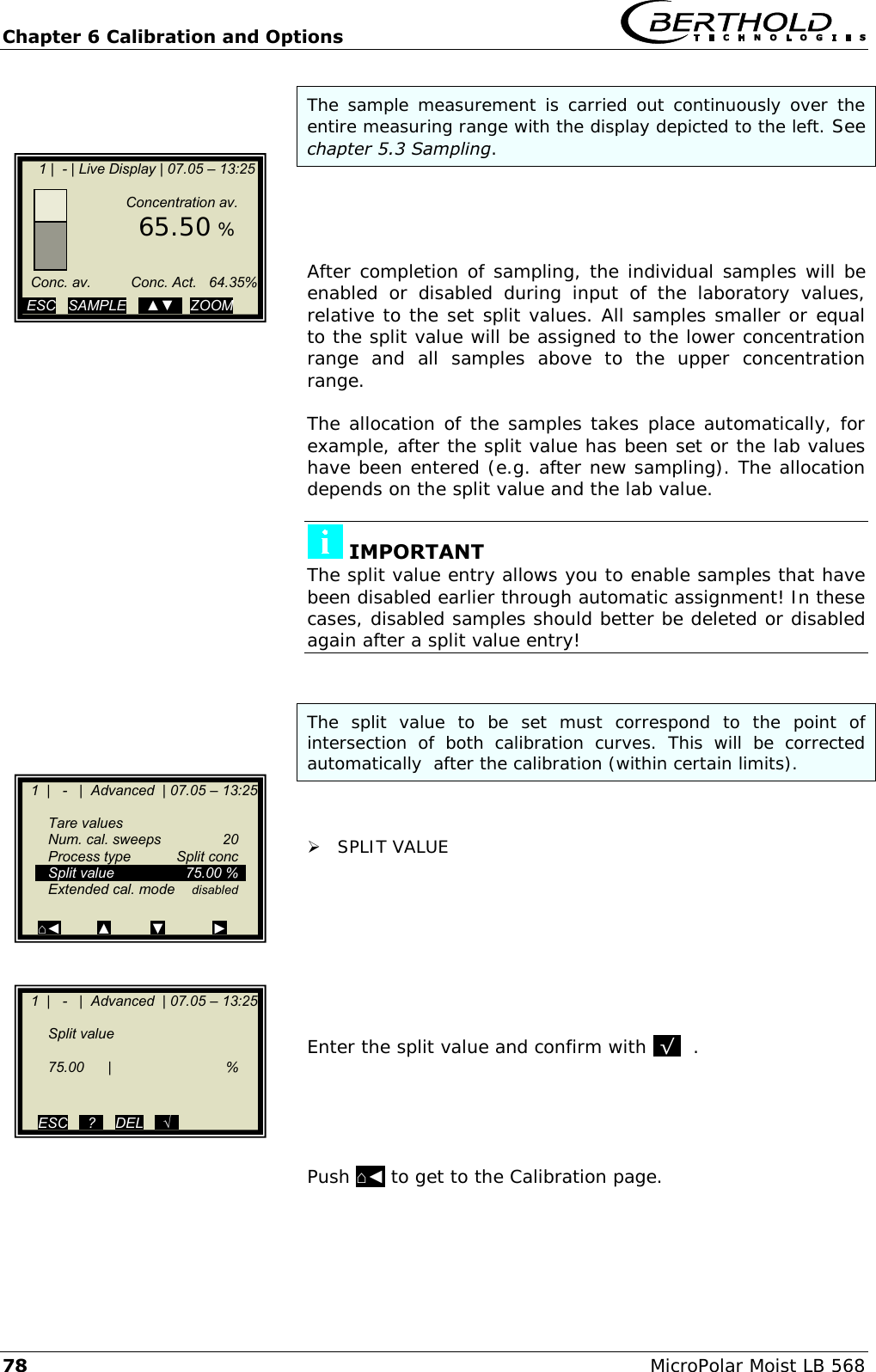
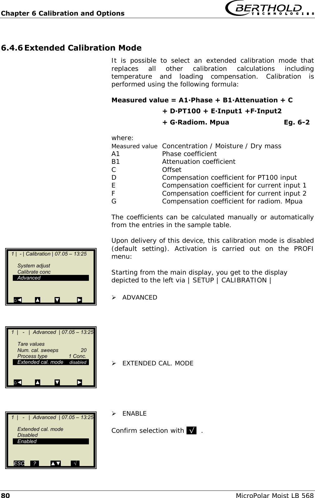
![Chapter 3 Software Functions 24 MicroPolar Moist LB 568 3.2.16 Sample Data (expanded) Current In 1: Display of the first compensation input (editable) Current In 2: Display of the second compensation input (editable) PT100: Display of the PT100 input (editable) PHI (fm): Display of the measured phase. Attenuation: Display of the measured attenuation. MPUA loading Displays the measured load [g/cm2] 3.2.17 Advanced Tare values: Option to enter tare values for phase and attenuation. The tare values are added to the phase stage and/or the attenuation prior to calibration. The calculation is carried out as follows: Eg. 3-3 and 3-4 Phase = Phasemeas - Phi Tare Attenuation = Attenuationmeas - Attenuation Tare Number of calibration sweeps: Freely adjustable number of sweeps over which a calibration point (in the course of automatic sample measurement) will be averaged. Process type: Select the operation mode: one concentration [1 measuring range] two concentrations [2 measuring ranges] split concentration [1 measuring range with switching point (split value) for coefficient switchover]. Split value: Setting of the switching point on a value basis. Extended calibration mode: Details see chapter 6.4.6. 1 | - | Advanced | 07.05 – 13:25 Tare values Num. cal. sweeps 20 Process type Split conc Split value 75.00 % Extended cal. mode disabled ⌂◄ ▲ ▼ ► 1 | 1/1 | Sample # 1 | 07.05 –13:25 Current In 1 Current In 2 PT100 PHI (fm) Attenuation MPUA loading ◄ DEL ▲▼ ..√..](https://usermanual.wiki/Berthold-Technologies/FCC02X03/User-Guide-2774185-Page-115.png)
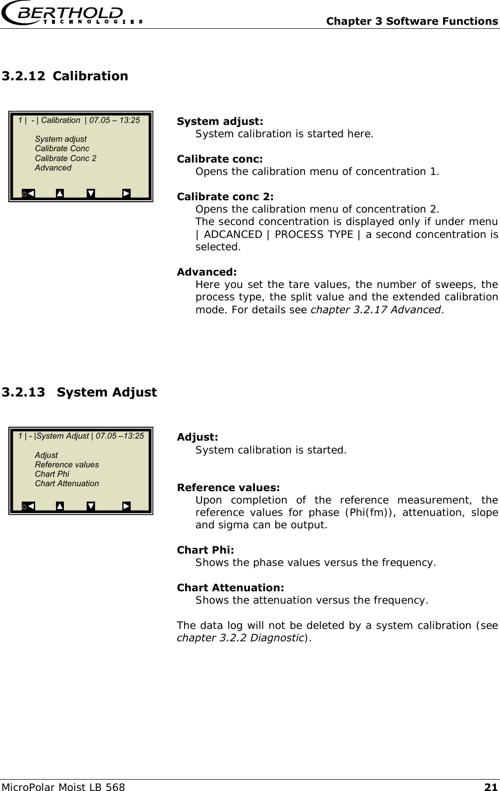
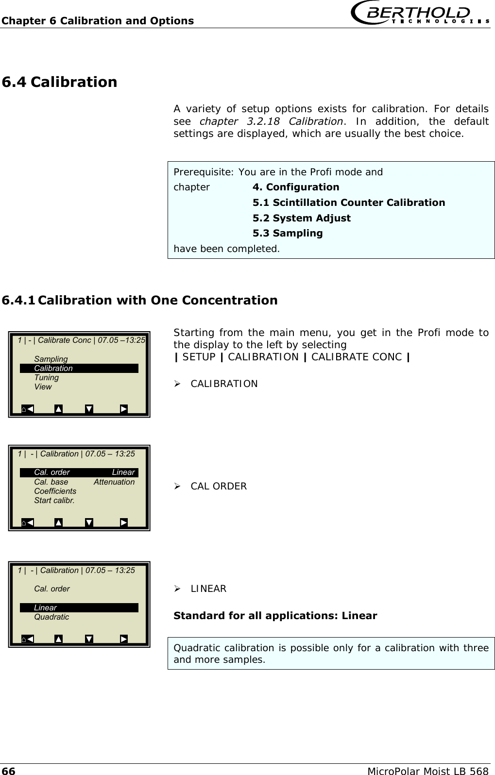
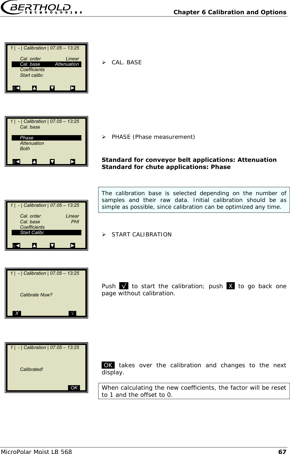
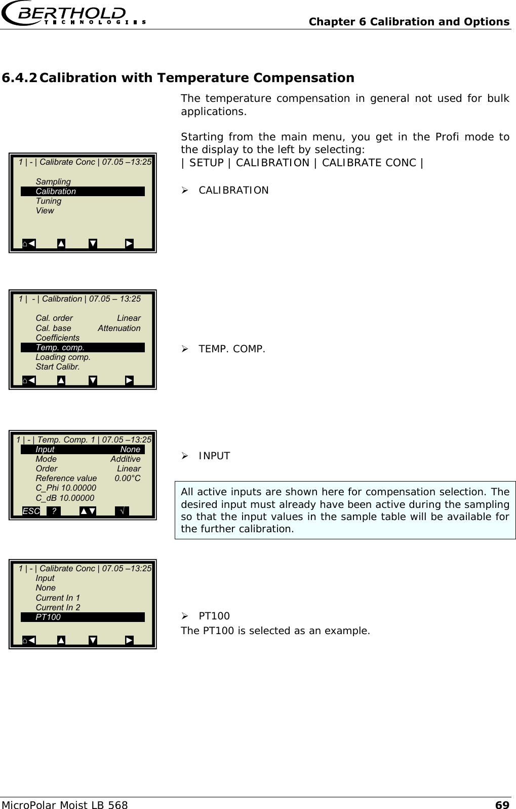
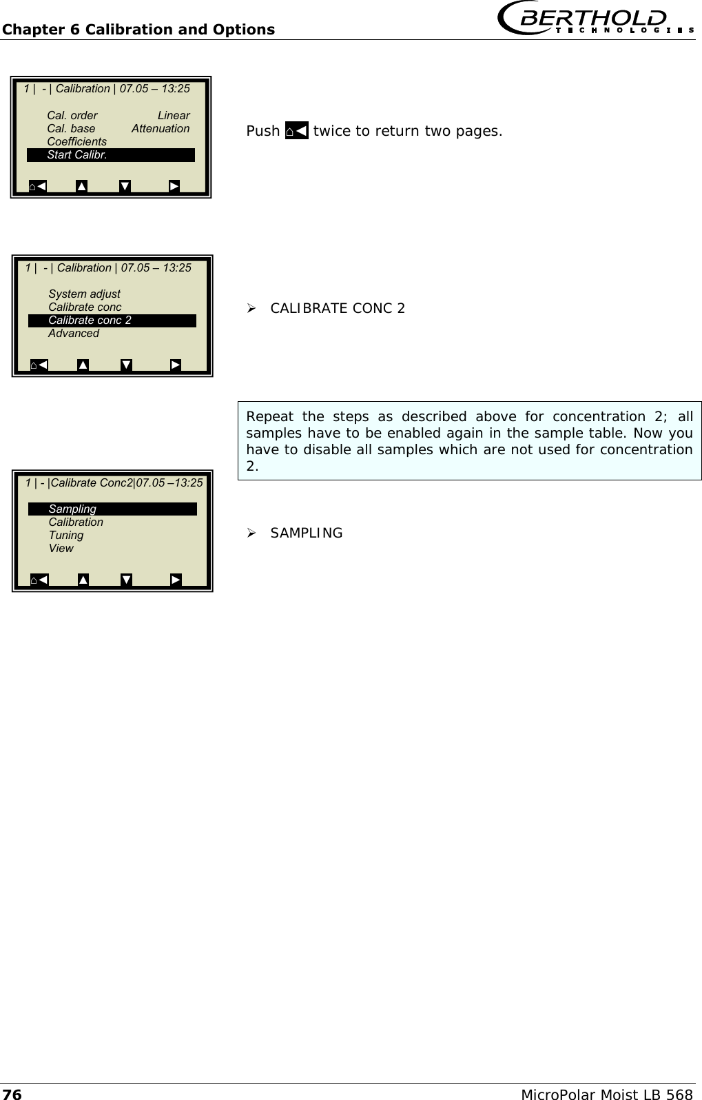
![Chapter 3 Software Functions MicroPolar Moist LB 568 25 3.2.18 Calibration Cal. order Here you define the calibration order [linear / quadratic] Default: Linear Cal. base The following parameters can be set: Phase Attenuation Phase and attenuation Default: Attenuation Coefficients: Here you can edit all coefficients for phase and attenuation. Default: A1 = 0, B1 = 0, C = 10 Temp. comp.: If at least one analog input is active, you may here assign the compensation and set the compensation parameters. For details please see chapter 3.2.19 Temperature Compensation. Loading comp. If at least one analog input is active, you may here assign the compensation and set the compensation parameters. For details please see chapter 3.2.20 Load Compensation. Start Calibration Starts the calibration using the parameters you have set earlier. 1 | - | Calibration | 07.05 –13:25 Cal. order Cal. base Coefficients Temp. comp. Loading comp. Start Calibration ⌂◄ ▲ ▼ ►](https://usermanual.wiki/Berthold-Technologies/FCC02X03/User-Guide-2774185-Page-116.png)
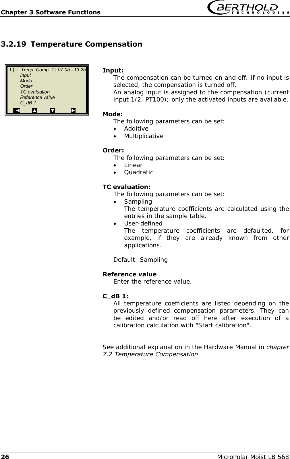
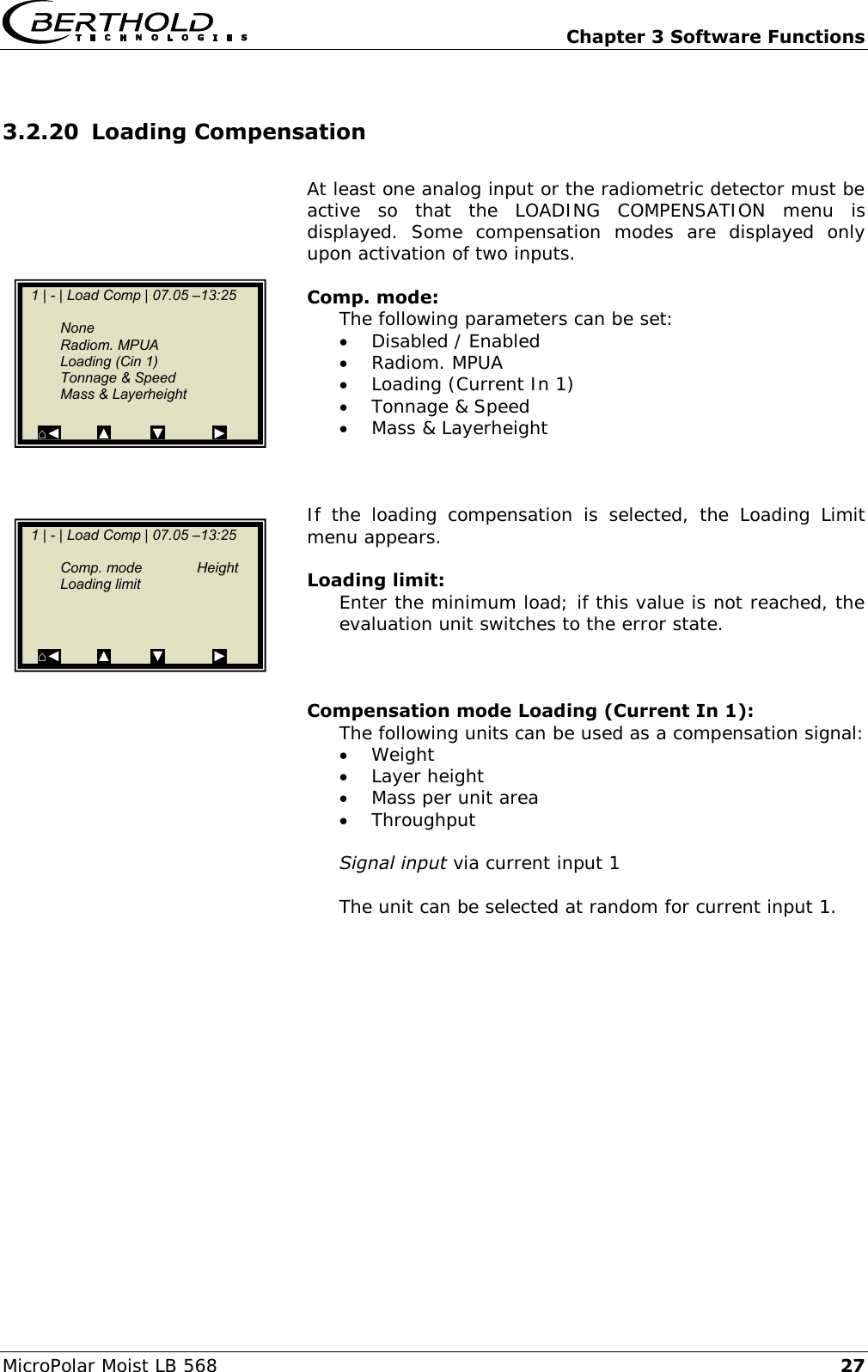
![Chapter 3 Software Functions 28 MicroPolar Moist LB 568 Compensation mode Tonnage & Speed (throughput & speed): Signal input Throughput via current input 1 Speed via current input 2 Unit Throughput [tons per hour; T/h] Speed [m/s] Min. load [Kg] The unit T/h must be selected for current input 1 and the unit m/s for current input 2. Compensation mode Mass & Layerheight (weight & layer thickness): Signal input Weight via current input 1 Layer thickness via current input 2 Unit Weight [Kg] Layer thickness [cm] Min. load [kg x cm] The unit kg must be selected for current input 1 and the unit cm for current input 2. Compensation mode Radiometric MPUA: The compensation signal is provided by the scintillation counter. Unit Mass per unit area [g/cm2] Min. load [g/cm2] See additional explanation in the Hardware Manual, chapter 3.3 Loading Compensation.](https://usermanual.wiki/Berthold-Technologies/FCC02X03/User-Guide-2774185-Page-119.png)

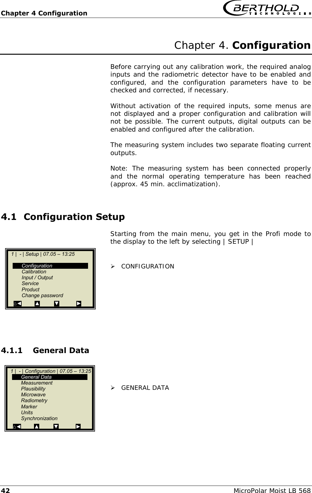
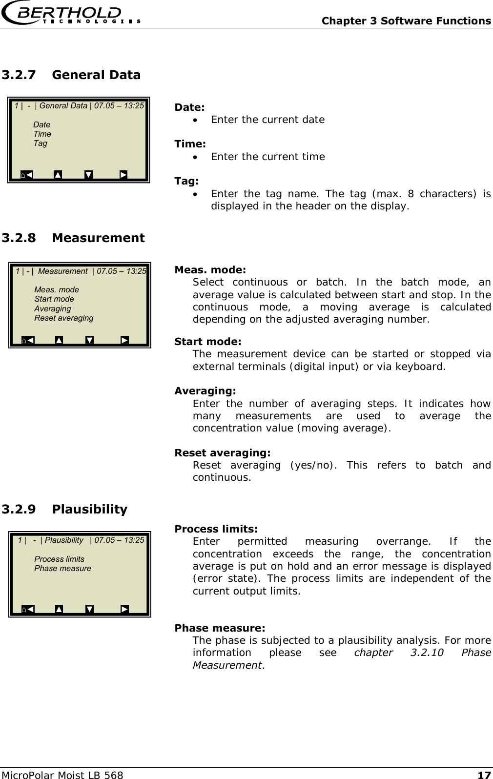
![Chapter 4 Configuration MicroPolar Moist LB 568 43 Example: Select the respective entry, edit and store it. DATE Push DEL to delete the entry and then enter the new date. Push .√. to confirm and store the changed date. TIP The colon for the time input (e.g. 13:25) is invoked by pushing the button [ . ]. 4.1.2 Measurement You have to check the settings on this display and adapt them to the measurement conditions. For example, you have to adapt the measurement mode, the start mode and the averaging to the actual operating conditions. 4.1.3 Plausibility Adjust the process limits. Allow for an absolute measuring overrange of ± 3%. Example: The measurement range is 5 -10% moisture. Enter 2 -13% moisture as process limits. The process limits are independent of the current output limits. For details on the phase measurement, see chapter 4.3 Configuration Plausibility. 1 | - | General Data | 07.05 – 13:25 Date 07.05.2004 Time 13:25 Tag App.1 ⌂◄ ▲ ▼ ► 1 | - | General Data | 07.05 – 13:25 Date 07.05.2004 | ESC ..?.. DEL ..√.. 1 | - | Measurement | 07.05 – 13:25 Meas. mode Continuous Start mode Keypad Averaging 20 Reset averaging no ⌂◄ ▲ ▼ ► 1 | - | Plausibility | 07.05 – 13:25 Process limits Phase measure ⌂◄ ▲ ▼ ►](https://usermanual.wiki/Berthold-Technologies/FCC02X03/User-Guide-2774185-Page-134.png)
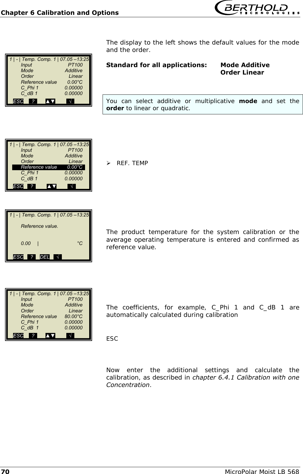
![Chapter 6 Calibration and Options 72 MicroPolar Moist LB 568 MIN. LOADING Enter minimum mass per unit area. Push √ to confirm and three times ⌂◄ to go back. Now enter the additional settings and calculate the calibration, as described in chapter 6.4.1 Calibration with one Concentration. 1 | - |Loading Limit|07.05 –13:25 Min. loading 0.01 ⌂◄ ▲ ▼ ► 1 | - |Loading Limit|07.05 –13:25 Min. loading [ ] 0.01 [-10 , 100000] ESC ..?.. ▲▼ ..√..](https://usermanual.wiki/Berthold-Technologies/FCC02X03/User-Guide-2774185-Page-163.png)
![Chapter 6 Calibration and Options 82 MicroPolar Moist LB 568 6.5 Typical Calibration Coefficients/Start Values For applications on the conveyor belt and in the measuring chute it holds: For dry mass measurement, A1 and B1 must be negative. Without loading compensation: ]cm/g[ 2Mpua11A or Eg. 6-3 ]cm/g[ 2Mpua61B Eg. 6-4 C: Concentration/moisture value during system calibration The Mpua can be calculated from Eq. 3-1 in the Hardware Manual, chapter 3.3 Load Compensation. With loading compensation using the mass per unit area: A1 = 1 or B1 = 6 for moisture measurement C: Concentration/moisture value during system calibration With loading compensation using current input 1: Example of compensation signals: - Mass flow, for example via a belt weigher - Material thickness, e.g. via distance measurement ]cm/g[ 2Mpua)1In Current(load alminNo1A or Eg. 6-5 ]cm/g[ 2Mpua)1In Current( load alminNo61B Eg. 6-6 C: Concentration/moisture value during system calibration The Mpua can be calculated from Eq. 3-1 in the Hardware Manual, chapter 3.3 Load Compensation.](https://usermanual.wiki/Berthold-Technologies/FCC02X03/User-Guide-2774185-Page-173.png)

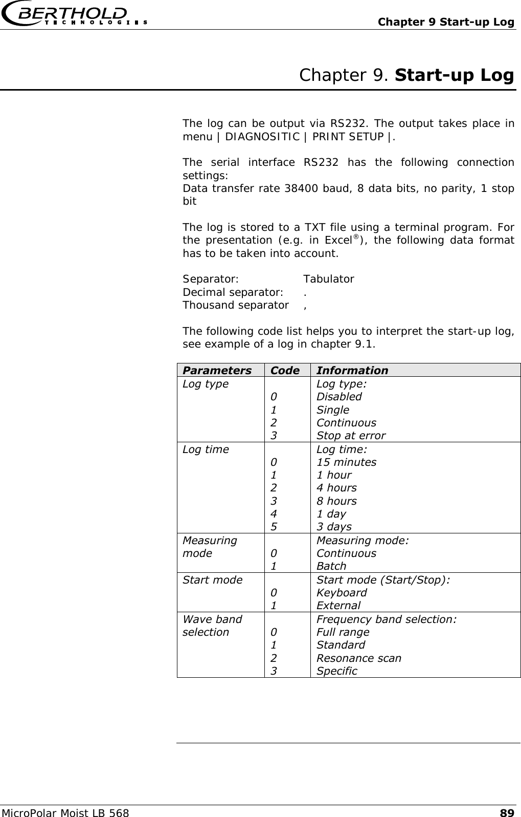
![Chapter 9 Start-up Log MicroPolar Moist LB 568 91 Parameters Code Information AO Assign Code 0 1 2 3 4 5 Assignment current output: None Concentration Concentration 2 Current In 1 Current In 2 PT100 AO Alarm select code 0 1 2 3 Error current output: 22 mA 3.5 mA Hold Value Range selection 0 1 Measuring range current output: 0 … 20 mA 4 … 20 mA Compensation input 0 1 2 3 Compensation input: None Current In 1 Current In 2 Pt100 AI Range selection 0 1 Measuring range current input: 0 … 20 mA 4 … 20 mA AI Enabled[2] Status of current input 2 DO Function 0 1 2 4 5 Function of the digital outputs: None Error Hold Alarm min. Alarm max. DO Assignment 0 1 2 3 4 Digital output: the min./max. alarm is assigned as follows: Concentration Concentration 2 Current In 1 Current In 2 PT100 DI Function selection 0 1 2 3 4 Function of the digital inputs: None Start/Stop Hold Sampling Product selection Printout mode 0 1 2 3 Mode of data output: None Line Table Line + table](https://usermanual.wiki/Berthold-Technologies/FCC02X03/User-Guide-2774185-Page-182.png)

![Chapter 9 Start-up Log MicroPolar Moist LB 568 93 9.1 Example Start-up Log Menu: Start of Setup: Start-up Log Interpretation: (* only relevant for service) Product Entry Product1 Product2 Prod.3 Prod.4 Datalog Log type : 1 Log type: see Code list Log time : 2 Log time: see Code list Number of errors : 2 Number of entries in the error log NTC temperature : 45.3 °C * max. NTC temperature : 46.7 °C * 9V power supply : 7.94 V * Info Tag: - Tag Device type: LB 568 Device type : Unique device ID number : 4294967295 Serial number : 4294967295 Final assembly number : 000-000 Software version : V1.00 Software release date : 31.08.2012 Software revision date Actual date : 01.09.2012 Date of recording Actual time : 18:03 Time of recording Measurement Measuring mode : 0 Measuring mode: see code list Start mode : 0 Start mode: see code list Filter damping value : 20 Averaging number Filter damping value[2] : 20 * Filter damping value[3] : 20 * Reset average : FALSE Reset averaging: Yes/No Plausibility Lower limit : 0 Min. process limit Upper limit : 100 Max. process limit Max. phase sigma : 500 Sigma max. Max. Phase at zero freq.(°) 170.00 °/GHz Residual phase max. Correlation Phi/Att : 0 Phase/attenuation ratio Auto-set mode : FALSE Auto set: On/Off Unwrap algor. EPS value : 500.00 ° * PhiM jump corr. enable : TRUE Phase jump correction, enabled: Yes/No PhiM jump corr. variance : 150.00 ° Variance for the phase jump correction PhiM jump corr. filter damp : 4 Averaging number for the phase jump correction PhiM jump corr. filter post correction : FALSE * Microwave Ref. cable length : 4.00 m Reference cable length Signal cable length : 4.00 m Signal cable length Wave band selection : 1 Frequency band: see code list Start frequency : 0 * Internal Attenuation : 0 * Marker Marker name : Mark1 Marker name for concentration Marker value : 50 Marker value for concentration Marker name[2] : Mark2 Marker name for concentration 2 Marker value[2] : 50 Marker value for concentration 2 System adjust Nbr of sweeps for reference : 10 Number of sweeps for system calibration](https://usermanual.wiki/Berthold-Technologies/FCC02X03/User-Guide-2774185-Page-184.png)
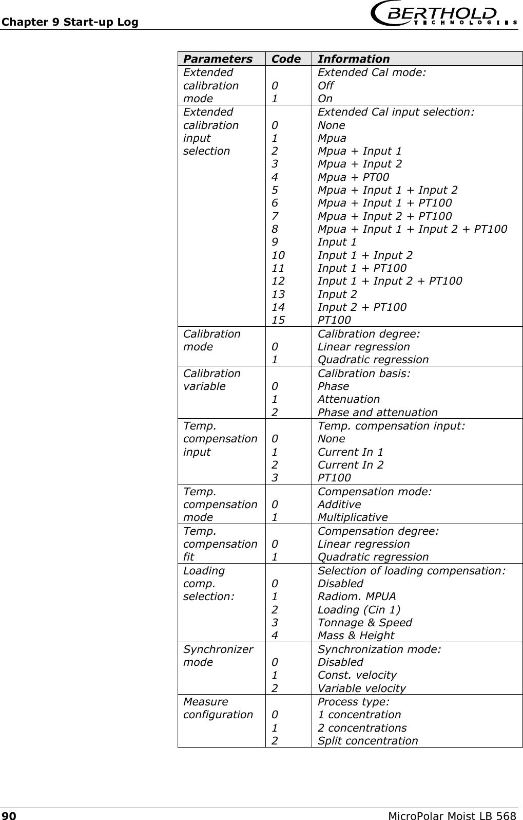
![Chapter 9 Start-up Log 94 MicroPolar Moist LB 568 Calibrate concen- tration 2 Extended calibration mode : 0 Extended Cal. mode: see Code list Extended calibration input selection: 0 Extended Cal input selection: see Code list Calibration mode : 0 Calibration degree: see code list Calibration variable : 1 Calibration basis: see code list Phase coefficients : 0 Phase coefficient A1 Phase coefficients[2] : 0 Phase coefficient A2 Attenuation coefficients : 0 Attenuation Coefficient B1 Attenuation coefficients[2] : 0 Atten. coefficient B2 Constant coefficient : 10 Constant C d coefficient 0 Comp. coefficient for PT100 input e coefficient 0 Comp. coefficient for current input 1 f coefficient 0 Comp. coefficient for current input 2 g coefficient 0 Comp coefficient for mpua Adjust factor : 1 Factor Adjust offset : 0 Offset Temp. compensation mode: 0 Compensation mode: see code list Temp. compensation input : 0 Compensation input: see code list Temp. compensation fit: 0 Compensation fit: see code list Temp. compensation reference : 0 Compensation reference value Phase coeff. for temp. comp. : 0 Comp. Phase coefficient K_Ph1 Phase coeff. for temp.comp.[2] : 0 Comp. Phase coefficient K_Ph2 Attenuation coeff. for temp.comp : 0 Comp. Atten. coefficient K_dB1 Attenuation coeff. for temp.comp[2] 0 Comp. Atten. coefficient K_dB2 Loading comp. selection : 0 Loading comp. selection: see code list Loading comp. lower limit : 0.01 Minimum load Synchronizer mode : 0 Synchronizer mode: see code list Current input1 distance to uWave : 0 Distance to the microwave measuring path Current input2 distance to uWave : 0 Distance to the microwave measuring path Radiometry distance to uWave : 0 Distance for the radiometric measuring path Plausibility for concen- tration 2 Lower limit : 0 Min. process limit Upper limit : 100 Max. process limit](https://usermanual.wiki/Berthold-Technologies/FCC02X03/User-Guide-2774185-Page-185.png)
![Chapter 9 Start-up Log MicroPolar Moist LB 568 95 Calibrate concen- tration 2 Calibration mode : 0 Calibration degree: see code list Calibration variable : 1 Calibration basis: see code list Phase coefficients : 0 Phase coefficient A1 Phase coefficients[2] : 0 Phase coefficient A2 Attenuation coefficients : 0 Atten. coefficient B1 Attenuation coefficients[2] : 0 Atten. coefficient B2 Constant coefficient : 10 Constant C d coefficient 0 Comp. coefficient for PT100 input e coefficient 0 Comp. coefficient for current input 1 f coefficient 0 Comp. coefficient for current input 2 g coefficient 0 Comp coefficient for mpua Adjust factor : 1 Factor Adjust offset : 0 Offset Temp. compensation mode: 0 Compensation mode: see code list Temp. compensation input : 0 Compensation input: see code list Temp. compensation fit : 0 Compensation degree: see code list Temp. compensation reference : 0 Compensation reference value Phase coeff. for temp. comp. : 0 Comp. Phase coefficient K_Ph1 Phase coeff. for temp.comp.[2] : 0 Comp. Phase coefficient K_Ph2 Attenuation coeff. for temp.comp : 0 Comp. Atten. coefficient K_dB1 Attenuation coeff. for temp.comp[2] 0 Comp. Atten. coefficient K_dB2 Loading comp. selection : 0 Loading comp. selection: see code list Loading comp. lower limit : 0.01 Minimum load Advanced Tare Phase (°/GHz) : 0.00 °/GHz Tare Attenuation (dB) : 0.00 dB Measure configuration : 0 Process type: see code list Range split value : 75 Split value Current output 1 AO Assign code : 1 Assignment: see code list AO Upper range value : 100.00% Upper value AO Lower range value : 0.00% Lower limit AO Current value : 4.00 mA Actual current AO Alarm select code : 2 Error current: see code list AO Error current value : 22.00 mA Error current value Current output 2 AO Assign code[2] : 0 Assignment: see code list AO Upper range value[2] : 100 Upper value AO Lower range value[2] : 0 Lower limit Range selection[2] : 1 Range AO Current value[2] : 4.00 mA Actual current AO Alarm select code[2] : 2 Error current: see code list AO Error current value[2] : 22.00 mA Error current value Current input 1 AI Enabled : 0 Disabled: 0 Enabled: 1 AI Range selection : 1 Range: see code list AI Upper range value : 100 Upper value AI Lower range value : 0 Lower limit AI Current : 0.00 mA Live current Current input 2 AI Enabled[2] : 0 Disabled: 0 Enabled: 1 AI Range selection[2] : 1 Range: see code list AI Upper range value[2] : 100 Upper value AI Lower range value[2] : 0 Lower limit AI Current[2] : 0.02 mA Live current](https://usermanual.wiki/Berthold-Technologies/FCC02X03/User-Guide-2774185-Page-186.png)
![Chapter 9 Start-up Log 96 MicroPolar Moist LB 568 PT100 input AI Enabled[3] : 0 Disabled: 0 Enabled: 1 PT100 value : 2.8 °C PT100 live value Relay 1 DO Function : 1 Function: see code list DO Assignment : 0 Assignment: see code list DO Threshold : 0.00% * DO Hysteresis : 5.00% * Relay 2 DO Function[2] : 2 Function: see code list DO Assignment[2] : 0 Assignment: see code list DO Threshold[2] : 0.00% * DO Hysteresis[2] : 5.00% * Digital inputs DI Function selection : 0 Function digital input 1: see code list DI Function selection[2] : 0 Function digital input 2: see code list DI Function selection[3] : 0 Function digital input 3: see code list Printout mode : 1 Data output: see code list Access level : 2 Access level: see code list Language : 1 Language: see code list Radiom. detector Radiometric detector measurement state: 0 Disabled 0 Enabled: 1 Cps filter damp : 10 Averaging of the count rate Cps validation mode : 1 Disabled 0 Enabled: 1 CPS max value : 100000 cps Maximum count rate CPS min value : 0 cps Min. count rate HV control mode : 0 Automatic: 0 Manual: 1 Actual HV : 450.0 V Current high voltage Detector software version : 1.2.4 Detector software version Detector unique id : 1161953277 Detector device ID no. Mass per unit area transducer state: 0 0 = no radiom. compensation enabled 1 = radiom. compensation enabled Absorption coefficient for MPUA calculation : 0.07 Absorption coefficient for MPUA calculation, MPUA = Mass per unit area Ray angle of radiation source : 0° Radiation angle Io rate : 0 cps Zero count rate Selected nuclide at I null determination : 0 0 = Cs137 1 =Am241 Io max. time : 180 s Max. recording time for Io Reference measurement done (Io) : FALSE Reference measurement done: Yes/No Nuclide selection : 0 0 = Cs137 1 =Am241 End of Setup End](https://usermanual.wiki/Berthold-Technologies/FCC02X03/User-Guide-2774185-Page-187.png)
![Chapter 9 Start-up Log MicroPolar Moist LB 568 97 Start of Reference Data System adjustment data: Product 1: Mean Atten.: 46.8509 dB Phase at fm: 42.6285 deg/GHz Phase offset: -825.586 deg Phase slope: 380,984 deg/GHz Phase correlation: 0.998212 Phase sigma: 0.24575 Frequency[GHz] Phase[Deg] Transformed Phase[Deg] Atten.[dB] 3.101 35.64 35.64 21.98 3.131 361.81 361.81 21.95 3.161 689.04 689.04 22.07 3.191 1014.44 1014.44 22.36 3.221 1339.01 1339.01 22.37 3.251 1664.16 1664.16 22.68 3.281 1989.9 1989.9 22.32 3.311 2319.19 2319.19 22.57 3.341 2642.87 2642.87 22.46 3.371 2972.88 2972.88 22.42 3.401 3296.79 3296.79 22.83 3.431 3623.71 3623.71 22.43 3.461 3949.32 3949.32 22.51 3.491 4275.35 4275.35 22.34 3.521 4601.84 4601.84 22.27 3.551 4929.07 4929.07 22.44 3.581 5254.83 5254.83 22.45 3.611 5582.38 5582.38 22.47 3.641 5907.4 5907.4 22.67 3.671 6230.12 6230.12 22.77 3.701 6489.69 6489.69 22.24 3.731 6755.95 6755.95 22.23 3.761 6922.09 6922.09 22.24 3.791 7387.71 7387.71 22.25 3.821 7854.85 7854.85 22.02 3.851 7854.85 7854.55 22.89 3.881 7387.71 7387.71 22.41 Start of Sample Data: Sampling: Product 1: Sample Data for Concentration 1: Sample: Active: Con .(%): Lab.(%): AIN1: AIN2: Temp. (°C): Phi. (°/GHz): Att.(dB): Mqua (g/cm2): 1|17.03 - 12:37 TRUE 40 40 0 0 0 -0.35 0.02 0.00 2|17.03 - 12:37 TRUE 35 35 0 0 0 30.33 5.08 0.00 3|17.03 - 12:45 TRUE 25 25 0 0 0 59.02 18.98 0.00 Correlation factor between lab and meas values: 1 End of Sample Data Do not use following data!](https://usermanual.wiki/Berthold-Technologies/FCC02X03/User-Guide-2774185-Page-188.png)