Berthold Technologies FCC02X03 Concentration / Moisture / Dry Mass / Density Measuring System User Manual LB 567
Berthold Technologies Concentration / Moisture / Dry Mass / Density Measuring System LB 567
UserManual.pdf
ID No. 41990BA2
Rev. No.: 02 15.06.2015
Software Version ≥ 1.0
Process Control
detect and identify
User's Guide
- Hardware Manual -
Concentration / Moisture
Measuring System
MircoPolar Moist
LB 568

MircoPolar Moist LB 568
The units supplied should not be repaired by anyone other than Berthold
Technologies Service engineers or technicians by Berthold Technologies.
In case of operation trouble, please address to our central service department
(address see below).
The complete user’s guide consists of two manuals, the hardware
description and the software description.
The hardware manual comprises the
component description
assembly instructions
electrical installation description
technical data
certificates
dimensional drawings
The software manual comprises the description of the
operation
software functions
calibration
error messages
The present manual is the hardware description.
Subject to change without prior notice.
BERTHOLD TECHNOLOGIES GmbH & Co. KG
Calmbacher Str. 22 75323 Bad Wildbad, Germany
Headquarters: Service:
Phone +49 7081 177 0 Phone +49 7081 177 111
Fax +49 7081 177 100 Fax +49 7081 177 339
industry@Berthold.com Service@Berthold.com
www.Berthold.com

Table of Contents
MircoPolar Moist LB 568 5
Table of Contents
Page
CHAPTER 1. SAFETY SUMMARY ........................................................................................................................ 7
1.1 SYMBOLS AND WARNINGS .............................................................................................................................. 7
1.2 GENERAL INFORMATION ................................................................................................................................. 8
1.3 GENERAL SAFETY INSTRUCTIONS ...................................................................................................................... 9
CHAPTER 2. GENERAL INFORMATION ............................................................................................................. 11
2.1 USE AND FUNCTION .................................................................................................................................... 11
2.2 INTENDED USE ........................................................................................................................................... 12
2.3 DEFINITIONS .............................................................................................................................................. 13
CHAPTER 3. SYSTEM DESCRIPTION ................................................................................................................. 14
3.1 PRINCIPLE OF MEASUREMENT ....................................................................................................................... 14
3.2 CALCULATION OF MEASURED VALUES ............................................................................................................. 15
3.3 LOADING COMPENSATION ............................................................................................................................ 17
3.3.1 Radiometric Mass per Unit Area Compensation ............................................................................ 18
3.4 MECHANICAL COMPONENTS ......................................................................................................................... 20
3.4.1 The Evaluation Unit ........................................................................................................................ 22
3.4.2 Horn and Spiral Antennas .............................................................................................................. 24
3.4.3 The Radiometric Measuring Path ................................................................................................... 26
3.4.4 Measuring Chute ............................................................................................................................ 29
3.4.5 High-frequency Cable ..................................................................................................................... 30
3.5 CONVEYOR MEASUREMENT CONFIGURATION ................................................................................................... 31
3.6 CHUTE MEASUREMENT CONFIGURATION ......................................................................................................... 32
CHAPTER 4. GETTING STARTED ....................................................................................................................... 33
4.1 TRANSPORT TO THE INSTALLATION SITE ........................................................................................................... 33
4.2 COMMISSIONING THE CONVEYOR BELT ........................................................................................................... 33
4.2.1 Components ................................................................................................................................... 33
4.2.2 Measuring Geometry and Measuring Conditions .......................................................................... 34
4.2.3 Installation of the Horn Antennas .................................................................................................. 37
4.2.4 Installation of the Spiral Antennas ................................................................................................. 40
4.2.5 Installation of the Radiometric Measuring Path ............................................................................ 42
4.2.6 Installation of the Evaluation Unit ................................................................................................. 44
4.2.7 Connecting the HF Cable ................................................................................................................ 45
4.3 COMMISSIONING THE CHUTE ........................................................................................................................ 46
4.3.1 Components ................................................................................................................................... 46
4.3.2 Measuring Geometry and Measuring Conditions .......................................................................... 46
4.3.3 Installation ..................................................................................................................................... 47
4.3.4 Installation of the Evaluation Unit ................................................................................................. 48
4.3.5 Connecting the HF Cable ................................................................................................................ 48
4.4 CONNECTING THE EVALUATION UNIT .............................................................................................................. 49
4.4.1 Pin Configuration of the Connector Strip ....................................................................................... 50
4.4.2 Connecting the Scintillation Counter .............................................................................................. 52
4.4.3 Digital Outputs, Relay .................................................................................................................... 53

Table of Contents
6 MircoPolar Moist LB 568
CHAPTER 5. SERVICE INSTRUCTIONS .............................................................................................................. 54
5.1 GENERAL INFORMATION .............................................................................................................................. 54
5.2 PARTS SUBJECT TO WEAR ............................................................................................................................ 54
5.3 INSTRUMENT CLEANING .............................................................................................................................. 54
5.4 BATTERY ................................................................................................................................................... 54
5.5 FUSE REPLACEMENT ................................................................................................................................... 55
CHAPTER 6. TECHNICAL DATA ........................................................................................................................ 56
6.1 TECHNICAL DATA EVALUATION UNIT .............................................................................................................. 56
6.2 TECHNICAL DATA HORN AND SPIRAL ANTENNAS .............................................................................................. 59
6.3 TECHNICAL DATA RADIOMETRIC MASS PER UNIT AREA MEASUREMENT ............................................................... 60
6.4 TECHNICAL DATA MEASURING CHUTE ............................................................................................................ 62
6.5 TECHNICAL DATA HF-CABLE ........................................................................................................................ 63
6.6 SERIAL DATA OUTPUT RS232 FORMAT .......................................................................................................... 64
CHAPTER 7. OTHER COMPENSATION OPTIONS .............................................................................................. 66
7.1 OPTIONAL LOADING COMPENSATION ............................................................................................................. 66
7.1.1 Mass per Unit Area Compensation ................................................................................................ 66
7.1.2 Layer Thickness Compensation...................................................................................................... 66
7.1.3 Weight/Throughput Compensation .............................................................................................. 67
7.1.4 Layer Thickness and Weight Compensation .................................................................................. 68
7.2 TEMPERATURE COMPENSATION .................................................................................................................... 69
7.3 SYNCHRONIZATION OF THE CURRENT INPUT SIGNALS ........................................................................................ 70
CHAPTER 8. RADIATION PROTECTION GUIDELINES ........................................................................................ 72
8.1 BASICS AND DIRECTIVES .............................................................................................................................. 72
8.2 EMERGENCY INSTRUCTIONS .......................................................................................................................... 75
CHAPTER 9. CERTIFICATES .............................................................................................................................. 76
9.1 EC DECLARATION OF CONFORMITY ................................................................................................................ 76
CHAPTER 10. TECHNICAL DRAWINGS ............................................................................................................. 77
10.1 DIMENSIONAL DRAWING EVALUATION UNIT CASE ........................................................................................ 77
10.2 ELECTRICAL WIRING DIAGRAM ................................................................................................................. 78
10.3 ELECTRICAL WIRING DIAGRAM SCINTILLATION COUNTER ............................................................................... 79
10.4 DIMENSIONAL DRAWINGS HORN AND SPIRAL ANTENNAS .............................................................................. 80
10.4.1 Horn Antenna and Horn Antenna Brackets ................................................................................... 80
10.4.2 Spiral Antennas ............................................................................................................................. 82
10.5 DIMENSIONAL DRAWINGS RADIOMETRIC MEASURING PATH .......................................................................... 83
10.5.1 Scintillation Counter with Axial Collimator .................................................................................... 83
10.5.2 Scintillation Counter with Radial Collimator ................................................................................. 84
10.5.3 Scintillation Counter with Bracket ................................................................................................. 85
10.5.4 Shielding Container LB 7440/5 with Mounting Plate .................................................................... 86
10.5.5 Mounting Plate for Shielding Container ........................................................................................ 87
10.6 INSTALLATION PROPOSAL AT THE CONVEYOR BELT ........................................................................................ 88
10.7 INSTALLATION PROPOSAL AT THE MEASURING CHUTE ................................................................................... 89
INDEX ............................................................................................................................................................. 90
Chapter 1 Safety Summary
MircoPolar Moist LB 568 7
Chapter 1. Safety Summary
1.1 Symbols and Warnings
In this user manual, the term Berthold Technologies stands for the
company Berthold Technologies GmbH & Co.KG.
To rule out bodily injury and property damage, please keep in
mind the warning and safety instructions provided in this operation
manual. They are identified by the following sings: DANGER,
WARNING, CAUTION or NOTE.
Indicates imminent danger. If it cannot be avoided, death
or most severe personal injuries may be the consequences.
Indicates a possibly dangerous situation. The consequences
may be death or most severe personal injuries.
Indicates a possibly dangerous situation. The consequences
may be minor or medium personal injuries.
Indicates a situation that may cause property damage
if the instructions are not followed.
IMPORTANT
Paragraphs with this symbol provide important information on the
product and how to handle it.
TIP
Includes application tips and particularly useful information.

Chapter 1 Safety Summary
8 MircoPolar Moist LB 568
Meaning of other symbols used in this documentation:
Warning: No intervention, do not alter anything
Requirement: Disconnect power
Requirement: Wear safety boots
1.2 General Information
The most important safety measures a summarized in this user
manual. They supplement the corresponding regulations which
must be studied by the personnel in charge.
Please pay attention to:
the national safety and accident prevention regulations
the national assembly and installation directions (for example,
E 60079)
the generally recognized engineering rules
the information on transport, assembly, operation, service,
maintenance
the safety instructions and information in these operating
instructions
the enclosed technical drawings and wiring diagrams
the characteristic values, limit values and the information on
operating ambient conditions on the type labels and in the data
sheets
the signs on the device
the country-specific licensing provisions.
Chapter 1 Safety Summary
MircoPolar Moist LB 568 9
1.3 General Safety Instructions
IMPORTANT
The instrument housing is protected according to protection type
IP 65 and is suitable for outdoor application. The instrument has
been tested by the manufacturer and is delivered in a condition
that allows safe and reliable operation.
For outdoor operation, the measuring systems have to be
protected against direct sunlight and rain, for example by a
suitable canopy.
IMPORTANT
Never change the installation and the parameter settings without
a full knowledge of these operating instructions, as well as a full
knowledge of the behavior of the connected controller and the
possible influence on the operating process to be controlled.
The systems may be used only in technically good order and only
according to regulations!
Only persons may work with the system who have been
authorized to do this and who have the proper qualification and
have received the necessary instructions! Installations and
modifications on the systems which may affect the operational
safety are not permitted!
IMPORTANT
All system components require non-corrosive ambient conditions
during transport, storage and operation.
IMPORTANT
If liquid gets inside the instrument, cut off the power supply. The
instrument has to be checked and cleaned by an authorized
service center.
Ambient conditions

Chapter 1 Safety Summary
10 MircoPolar Moist LB 568
Electrical shock hazards
Disconnect power to ensure that contact with live part is avoided
during installation and when servicing.
Turn off power supply before opening the instrument. Work on
open and live instruments is prohibited.
Caution! Possible hazard, property damage!
For the device type:
LB 568-02 MircoPolar Moist (ID no. 41990-02)
If the 24 V DC auxiliary energy is connected, the + and – poles
must be connected correctly. There is no reverse voltage
protection!
Spare fuses must match the rating specified by the device
manufacturer. Short-circuiting or manipulation is not permitted.
IMPORTANT
The LB 568 and all ancillary units have to be connected to mains
via grounded connection.
IMPORTANT
The concentration measuring instrument LB 568 may only be
installed, serviced and repaired by qualified persons.
Qualified persons are persons who through their professional
training have acquired sufficient skills in the respective field and
who are familiar with the pertinent national labor safety directions,
accident prevention directions, guidelines and with good
engineering practice. They must be capable of safely assessing the
result of their work and they must be familiar with the contents of
these operating instructions.
The guidelines for radiation protection and the stipulations of the
handling license have to be complied with.
Any change in frequency or any other manipulation on the micro-
wave device will result in a loss of the frequency approval and will
be prosecuted.
The microwave modules do not include any replaceable
components and must not be opened.
Qualified persons

Chapter 2 General Information
MircoPolar Moist LB 568 11
Chapter 2. General Information
2.1 Use and Function
The MircoPolar Moist LB 568 has been designed as a
concentration/moisture measuring system and may be used only
for this purpose. If the devices are used in a manner that are not
described in this user manual, the protection of the devices is
impaired and the warranty claim is void.
Berthold Technologies warrants and/or guarantees only that the
devices comply with its published specifications. The LB 568 may
be installed only in an undamaged, dry and clean condition.
Alterations and modifications on the system components are not
permitted.
The LB 568 is not qualified as a "safety-relevant measurement".
The standards and guidelines the LB 568 complies with are
itemized in these device instructions in chapter 9.1 EC Conformity
Declaration.
The protection type of the LB 568 according to IEC 60529 is max.
IP 65.
The following use is inappropriate and has to be prevented:
Use under other conditions and prerequisites than those
specified by the manufacturer in his technical documents, data
sheets, operating and assembly instructions and other
specifications.
Use after repair by persons who were not authorized by
Berthold Technologies.
Use in a damaged or corroded state.
Operation with open or inadequately closed cover.
Operating with inadequately tightened adapters and cable
fittings.
Operation without observing the safety precautions foreseen by
the manufacturer.
Manipulating or bypassing existing safety facilities.
Authorized persons are persons who are foreseen for the
respective activity, either based on statutory regulations, or who
have been licensed by Berthold Technologies for certain activities.
The LB 568 comply with part 15 of the FCC Rules (FCC: Federal
Communications Commission). These devices fulfill the
requirements regarding immunity to interference and emitted
interference and are licensed for operation.
Conformity to
standards
Protection type
Warning
against misuse
Authorized persons
Frequency
licenses

Chapter 2 General Information
12 MircoPolar Moist LB 568
2.2 Intended Use
The measuring system LB 568 has been designed to determine the
water or moisture content or the concentration of almost any
material. The microwave measurement technique employed
enables non-contact on-line measurement.
The layer of material to be measured on a conveyor belt or in a
measuring chute made of non-conductive material can be directly
irradiated by the microwaves. The measurement is carried out
through the walls or through the conveyor belt. Varying layer
thicknesses and bulk densities of the measured product can be
compensated by the additional radiometric mass per unit area
measurement.
During operation, the LB 568 sends out electromagnetic radiation.
The transmitting antenna is installed so close to the bottom side of
the conveyor belt or to the measuring chute that the emitted
electromagnetic radiation passes almost completely through the
product.
To ensure proper function of the measuring system, please pay
attention to the following:
TIP
The material to be measured may be electrically conductive
only to a limited degree.
The product must not contain any gas bubbles or gas bubbles
have to be compressed with adequate pressure when carrying
out measurements in pipelines.
The ion concentration, e.g. salt content, has to be nearly
constant.
FCC
license certificate

Chapter 2 General Information
MircoPolar Moist LB 568 13
Definitions
Attenuation
Weakening of the microwave signals, microwaves measurement
effect.
Evaluation unit
Evaluation Unit
Factory setting
See factory setting
Factory setting
All parameters have been set by the manufacturer using
standard values. In most cases this simplifies calibration of the
instrument significantly. Despite factory setting, calibration
should always be performed.
HF cable
High frequency cable
MBq
Mega Becquerel
This unit is the activity of a source. Each Bq corresponds to one
decay per second.
1 MBq = one million decays
Mpua
Mass per unit area
mCi
Milli Curie
This unit is also used for the activity of a source. However, this
is the older unit that has been replaced by the unit MBq. (1 mCi
= 37 MBq)
Microwaves
Electromagnetic waves in a certain frequency range.
Nuclide / isotope
Substance of the radiation source. For the moisture
measurement on a belt or in a chute usually Cesium-137 (Cs-
137), rarely Americium-241 (Am-241)
Phase
Phase or phase shift, microwave measurement effect
Softkeys
Buttons associated with the software.
TC
Temperature compensation
Chapter 3 System Description
14 MircoPolar Moist LB 568
Chapter 3. System Description
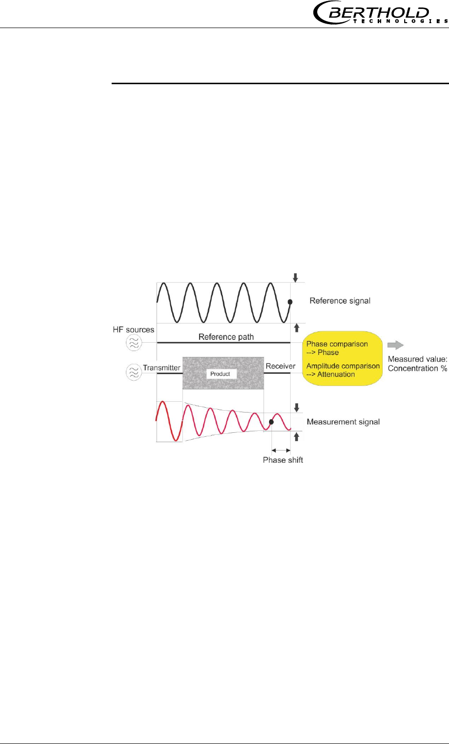
3.1 Principle of Measurement
The microwaves transmit the product being measured; their
propagation speed is slowed down (= phase shift) and their
intensity is damped (= attenuation). Figure 3-1 illustrates the
principle of measurement: The propagation speed of microwaves
passing through the product being measured is slowed down
(phase shift) and their intensity (attenuation) is reduced, relative
to a reference signal. This influence is dependent on the measured
concentration and moisture content.
Figure 3-1:
Schematic diagram:
Microwaves are
changed by the product

Chapter 3 System Description
MircoPolar Moist LB 568 15
3.2 Calculation of Measured Values
The microwave parameters phase shift or short phase and
attenuation are calibrated according to an automatic plausibility
analysis.
During calibration, a concentration value is assigned through
sampling to the phase and/or attenuation. The calibration runs
automatically and the sampling process is supported by the
evaluation unit.
The concentration content to be detected in the material is usually
dependent linear on the phase shift and the attenuation. For this
reason, a linear calibration can be calculated as follows.
C
Load
nattenuatioB
Load
phaseA
value Measured
Eq. 3-1
where:
Measured value Concentration / Moisture / Dry mass
A, B, C Coefficients of respective calibration function
Which of the parameters, phase, attenuation or both will be used
for the calibration depends on the size of and the disturbing
influence on the measuring effect. For example, the attenuation is
more sensitive to electrolytic conductivity (salt content).
In contrast to conventional microwave attenuation measuring
instruments, MircoPolar Moist is using a wide frequency band both
in the phase measurement and in the attenuation measurement.
Such a measurement permits a continuous verification of the
plausibility of the results of a measurement. The user can define
limit values for a desired plausibility range.
The measuring accuracy can be increased further through a
combination of attenuation and phase measurement only for some
special applications. Any possibly remaining grain size influence
that may occur in a pure phase measurement can be reduced by
using the combined measurement.

Chapter 3 System Description
16 MircoPolar Moist LB 568
Limitations
Weakly bound water can be detected depending on the
strength of the binding. Thus, the measuring effect may be
dependent on the grain size distribution and the chemical
properties of the product being measured, provided this
changes the binding of water to the solid matter.
Walls made of plastic, rubber or insulation materials with fairly
low dielectricity hardly affect the measurement and are
calibrated at a constant level.
Ice and crystal water cannot be measured because the water
molecules cannot rotate freely (ice and crystal are dry).
Conductive materials such as graphite or coke cannot be
transmitted by microwaves. Metal walls can also not be
transmitted by microwaves. Metal-reinforced conveyor belts may
be transmitted only under certain conditions (see chapter 4.2.3
Installation of the Horn Antenna and 4.2.5 Installation of the
Radiometric Measuring Path).
The LB 568 allows you to calibrate, display and output two
concentrations: Conc1 and Conc2. You have to enter the
calibration coefficients separately for concentration 1 and 2. For
more information please refer to the Software Manual.
In addition to the water content, the product temperature,
product density and a varying material load (varying microwave
irradiation path) may have an influence on the phase and
attenuation. This influence has to be compensated for during
calibration.
In general, a temperature compensation (TC) is not required for
bulk material. If the product temperature has a significant impact
on the microwave measuring signals phase or attenuation, a TC
should be connected (see chapter 7.2 Temperature
Compensation). The temperature influence depends on the product
and water content.
Compensation
Chapter 3 System Description
MircoPolar Moist LB 568 17
3.3 Loading Compensation
The microwave irradiates the product to be measured and detects
all changes in the product. Example conveyor belt, see Fig. 3-2:
Figure 3-2:
Material profile on
the conveyor belt
The entire material cross-section is transmitted. If the material
layer thickness or the bulk density changes (with constant
moisture), then the microwave signals will be affected.
The goal of the loading compensation is to compensate for this
influence. This is done through standardization with regard to the
parameters layer thickness and bulk density which correspond to
the mass per unit area:
Load = mass per unit area [g/cm2] = ∙ d Eq. 3-2
where:
bulk density [g/cm3]
d material layer thickness [cm]
See Eq. 3-1: the standardization is done through division of the
phase and attenuation data by the load.
A mass per unit area compensation need not be performed when
the layer thickness and bulk density are constant in a fixed
measuring geometry. This is the case, for example, if conveyor
belts are always loaded with the same level, or if the filling level in
chutes is always the same, and the material has a constant
density.
If the loading compensation is not required and not selected, the
load is set to 1 (see Eq. 3-1):
Load = 1 Loading compensation not enabled
Chapter 3 System Description
18 MircoPolar Moist LB 568
Depending on the type of load fluctuations, there are several
possibilities for compensation; typically, the radiometric mass per
unit area compensation is used, which is described below.
At constant bulk density or if the mass per unit area is already
known, one may not need the radiometric measurement path
under certain circumstances. In this case, there are alternative
possibilities for compensation, see chapter 7.1 Optional Loading
compensation.
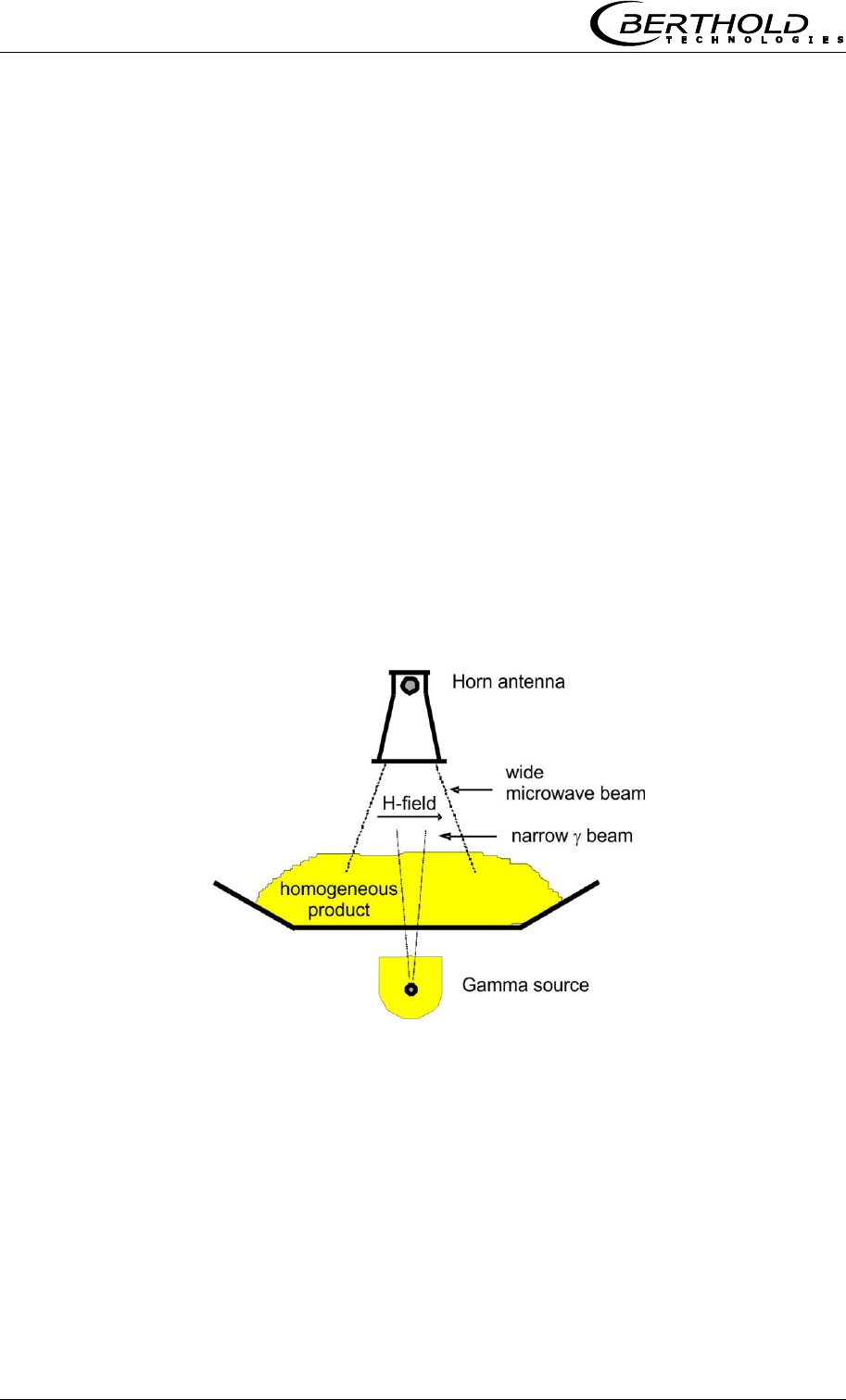
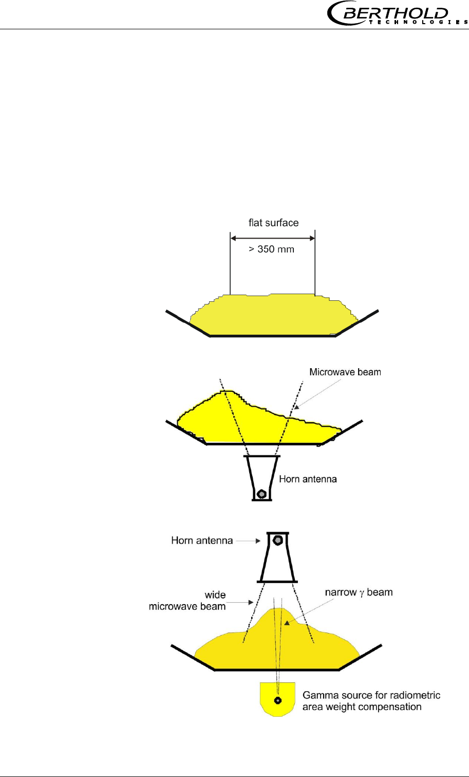
3.3.1 Radiometric Mass per Unit Area
Compensation
The influence of a varying material layer thickness and bulk
density disappears through standardization with regard to the
irradiated mass per unit area. The compensation is calculated as
follows:
Load = mass per unit area [g/cm2] Eq. 3-3
The radiometric measurement path supplies the mass per unit
area signal.
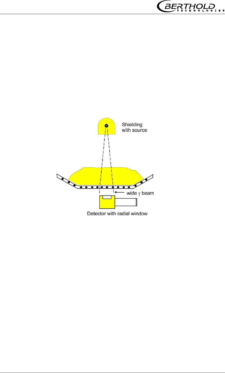
Figure 3-3:
Microwaves and gamma
radiation field at the
conveyor belt

Chapter 3 System Description
MircoPolar Moist LB 568 19
The radiometric mass per unit area measurement is based on the
physical effect that gamma radiation passing through the material
to be measured is subject to an exponential intensity attenuation
(see Figure 3-3). The intensity attenuation can be described by the
law of absorption:
d
0eII
Eq. 3-4
Where:
µ = absorption coefficient
= bulk density
d = layer thickness
I = actual count rate
I0 = zero count rate
Mpua = mass per unit area
Io is the intensity of the unattenuated radiation and μ the
material-specific attenuation coefficient (absorption coefficient).
This is specified as the default value for the chosen isotope (e.g.
Cs-137 source, μ = 0.07), but can be adjusted.
The residual radiation still arriving at the scintillation of the
intensity I is a measure of the mass per unit area (Mpua).:
I
I
ln
1
Mpua 0
Eq. 3-5
A constant distance is assumed between the radiation source and
scintillation counter.
The thickness of a wall to be irradiated additionally, or the
conveyor belt, is calibrated during the zero measurement, i.e. it
does not have any influence on the measuring effect. The intensity
of the radiation source decreases over time. The period in which it
has fallen to half its initial intensity - the half-life - depends on the
radiation source. Micro-Moist Polar compensates for the source
decay automatically depending on the selected radiation source.
Therefore, it is important to enter a correct date!
Chapter 3 System Description
20 MircoPolar Moist LB 568
3.4 Mechanical Components
The measurement system consists of the evaluation unit (short
EVA, Figure 3-4), one pair of antennas with HF cable (short HF
cable) and the radiometric mass per unit area measurement (short
radio Mpua). The antenna pair consists either of two identical horn
or spiral antennas, see Figure 3-5. The radiometric mass per unit
area system consists of the point source with scintillation container
and scintillation counter, see Figure 3-6.
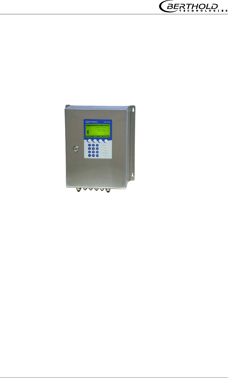
Figure 3-4:
Evaluation unit
MircoPolar Moist
Chapter 3 System Description
MircoPolar Moist LB 568 21
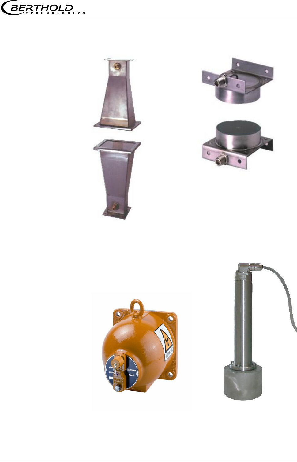
Figure 3-5:
From left:
Horn antenna pair,
spiral antenna pair
Figure 3-6: From left:
Point source shielding,
scintillation counter with
axial collimator
Chapter 3 System Description
22 MircoPolar Moist LB 568
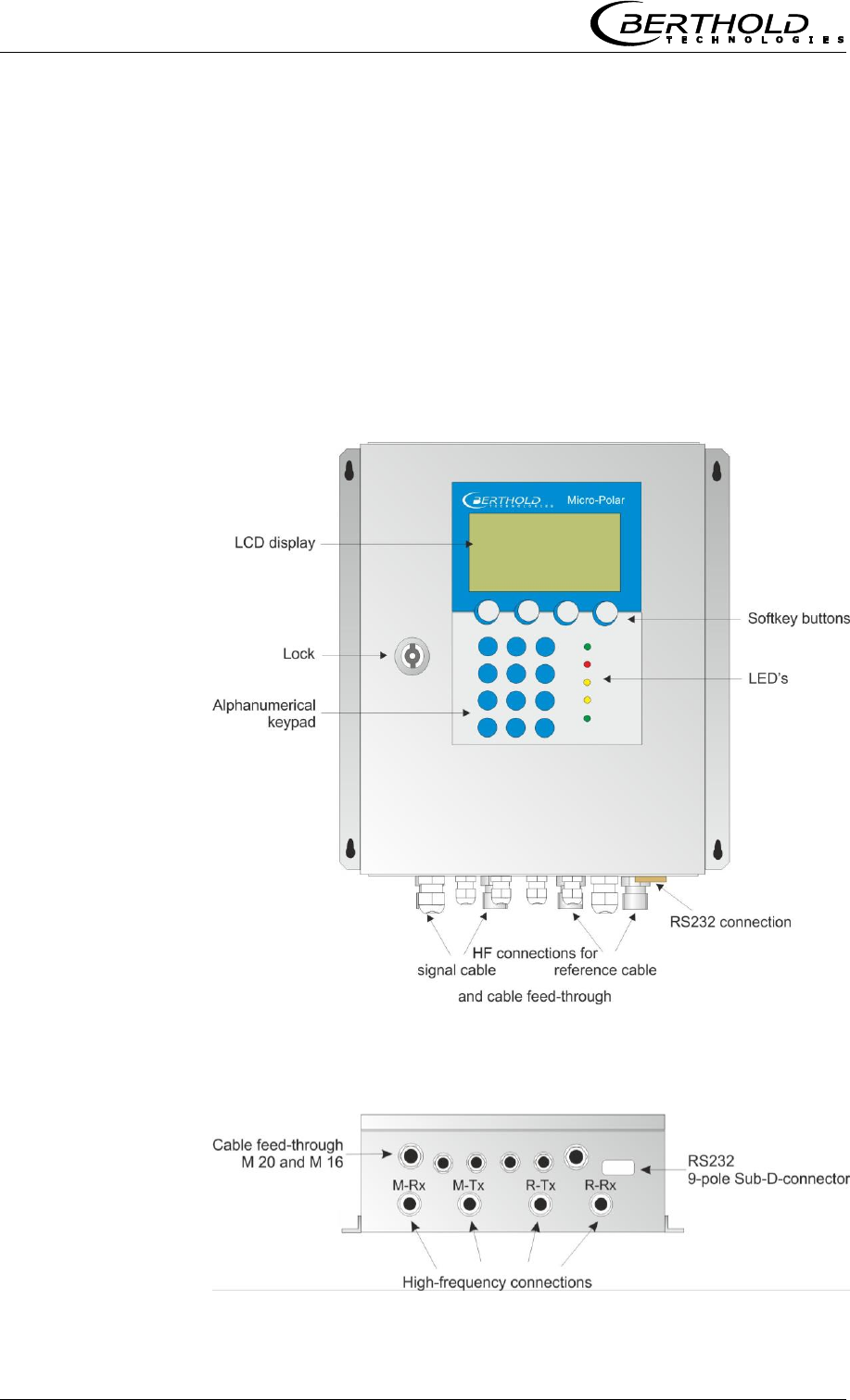
3.4.1 The Evaluation Unit
The evaluation unit comprises the evaluation computer with
microwave unit and radiometry board. The microwaves are
generated, received and analyzed in the microwave unit. Signal
processing and communication take place in the evaluation
computer. On the radiometry board there is a screw terminal strip
for connection of the scintillation counter; the communication
(RS485) and the auxiliary power supply of the scintillation counter
take place via this screw terminal strip. For simple operation, the
measuring system includes a display, 4 softkeys and an
alphanumeric keypad. Different functions are assigned to the
softkeys on the display. An RS232 interface is included on the
bottom of the device.
Figure 3-7:
Front view of the
evaluation units
Figure 3-8:
Evaluation units -
bottom view

Chapter 3 System Description
MircoPolar Moist LB 568 23
LED’s on the Front Panel
Five LED’s on the instrument front panel indicate the instrument
status.
LED
Function
Run
On: Device in measurement mode
Flashing + ERROR LED off: Device in the warning
or stopped state. In the warning state, a display
message with error code indicates the cause (see
Software Manual, chapter 8. Error Lists and Device
States).
Error
On: Device in error state. A display message with
error code indicates the cause (see Software
Manual, chapter 8. Error Lists and Device States).
Canceled after reset or if error has been eliminated
Signal 1
Display depending on the selected function of relay
1, possible functions:
error, alarm min., alarm max., measurement
stopped.
Signal 2
Display depending on the selected function of relay
2, possible functions:
error, alarm min., alarm max., measurement
stopped.
Comm
Communication active, e.g. via RS232
For a description of the device states please see the Software
Manual, chapter 8. Error Lists and Device States.
Terminal blocks
The electrical connections of the LB 568 are located on two
connector strips in the wall housing. They are accessible from the
front by opening the cover. There, you also find the fuses and a
test switch (see Fig. 5-1). The high-frequency connections are
located on the outside of the housing. All other elements,
especially the live elements (on the motherboard) are provided
with a protection cap.

Chapter 3 System Description
24 MircoPolar Moist LB 568
3.4.2 Horn and Spiral Antennas
Various types of microwave antennas are available for moisture
measurements on a conveyor belt or in a chute, taking into
account the different geometries of the respective application.
There are each an identical pair of antennas (transmitter and
receiver) that are connected to the evaluation unit via an HF cable.
Horn antenna
Spiral antenna
Polarization
Linear
Circular
Distance (field
size)
up to 3 m
0.1 to 0.75 m
Application
Conveyor belt, bunker,
steel reinforcement
possible
Conveyor belt, bunker,
steel reinforcement not
possible, belt without
strong troughing
Assembly
conditions
Vertical or oblique to the
belt, coupler parallel to
the flow direction of the
material (exception:
steel-reinforced belt).
Vertical position
Product being
measured
General
Only homogeneous
material for phase
measurement.
Material with direction-
dependent
inhomogeneities, for
example, chips: only for
attenuation measurement
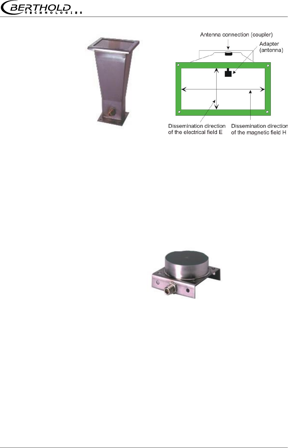
Horn antenna
The horn antenna is made out of stainless steel, see Fig. 3-9. The
antenna openings are closed tightly by plastic windows. The horn
antenna is a special construction where the wave guided in the HF-
cable goes over into a free wave. The magnetic field disseminates
vertically and the electrical field horizontally to the adapter (see
Fig. 3-9).
If dust deposits may occur, these windows should be cleaned
regularly. Dust depositions distort the results relative to their mass
per unit area and their water contents. The antennas do not
contain any electronic components; however, they should be
protected against mechanical damage.
Chapter 3 System Description
MircoPolar Moist LB 568 25
Figure 3-9: From left:
Horn antenna,
horn antenna with a
view through the window
Spiral antenna
The spiral antenna sends or receives microwaves in circular
polarization.
The spiral antenna is a near-field antenna and should be used only
for distances between 0.1 and 0.7 m. On materials including
inhomogeneities that change the direction of the microwaves it can
be employed only with the attenuation measurement.
Figure 3-10:
Spiral antenna
Chapter 3 System Description
26 MircoPolar Moist LB 568
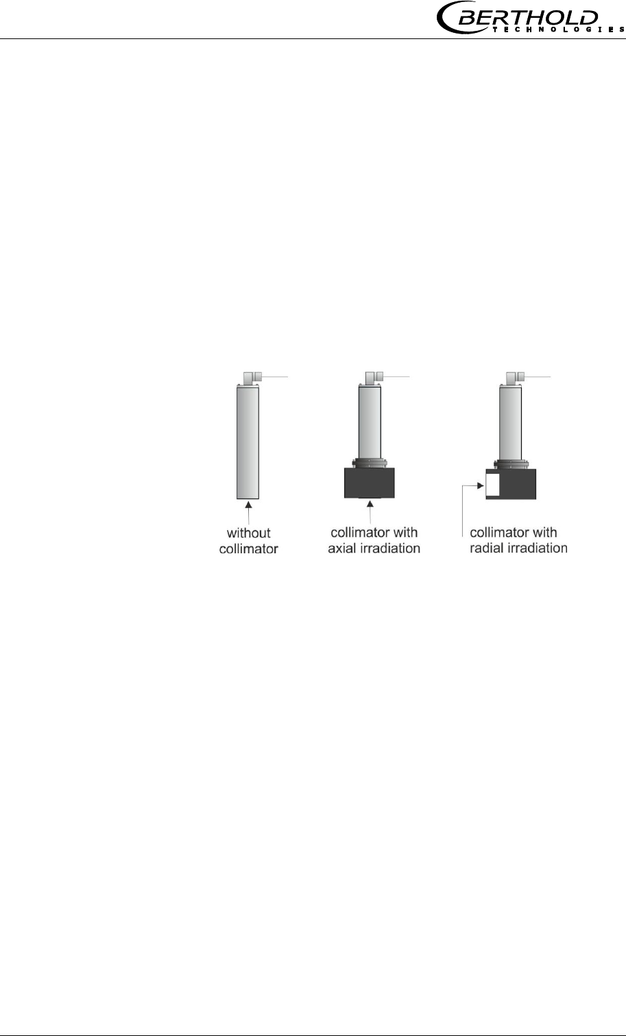
3.4.3 The Radiometric Measuring Path
The radiometric measuring path consists of
- a scintillation counter
- a radiation source (Cs-137 or Am-241) installed in
a lockable shielding
Scintillation counter
Two scintillation counter versions with different collimators are
available: the axial and radial collimator. With the axial collimator,
the entrance window is located on the front side, with the radial
collimator on the side, see Figure 3-11.
Figure 3-11:
Scintillation counter with
and without collimator
Radiation source
Cesium (Cs-137) and Americium (Am-241) gamma emitters are
used as radiation sources.
Chapter 3 System Description
MircoPolar Moist LB 568 27
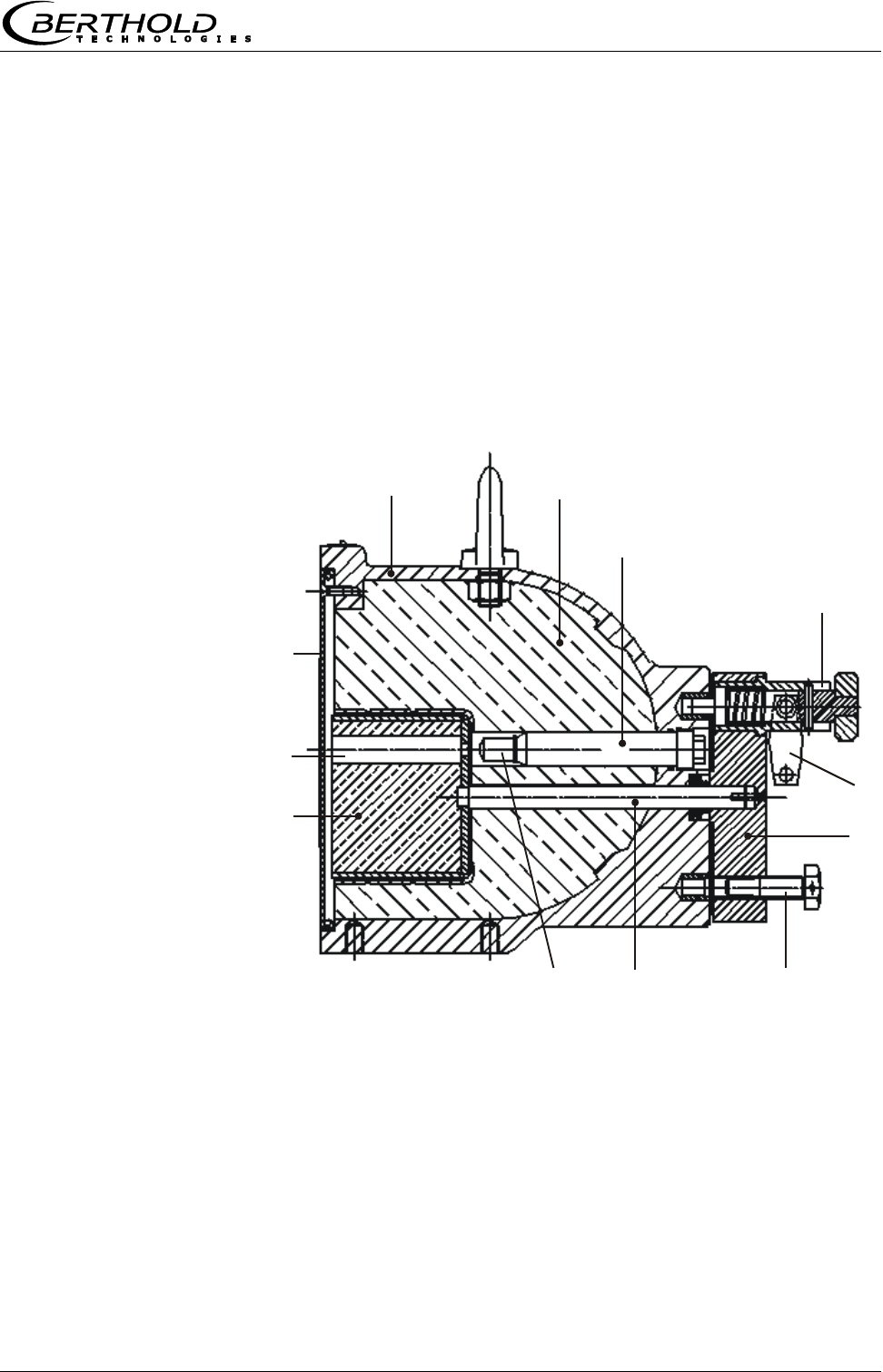
Shielding
The point source Cs-137 is built into the shielding type LB 744X.
The shielding container is made of a sturdy cast iron or stainless
steel housing, see Figure 3-12. The container front side is closed
by a metal plate. The radiation exit channel can be closed by a
built-in rotating diaphragm. The diaphragm is operated from the
rear via a lever which in the open and closed position can be
secured by a lock. The source is installed so that it is also
protected by the lock against unauthorized removal.
Alternatively, the lock can be pneumatically actuated (see
following page).
Figure 3-12:
Cross-section shielding
container with source
12
3
6
7
8
9
10
11
12
5
4
1
Shell
7
Lock
2
Lead filling
8
Rotation axis
3
Source bracket
9
Radiation source
4
Spring pin
10
Locking core
5
Padlock
11
Radiation exit channel
6
Locking lever
12
Cover plate
Chapter 3 System Description
28 MircoPolar Moist LB 568
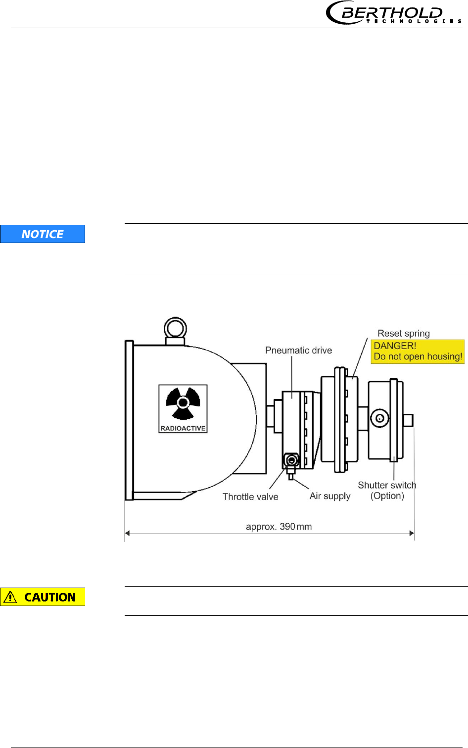
Shielding with pneumatically operated lock and shutter
switch (option)
A pneumatic lock with switch contacts indicating the position of the
lock is available as a special version.
The pressurized air moves the locking diaphragm to the OPEN
position. If the pressurized air is turned off or in case of failure, a
spiral spring turns the locking diaphragm back to the CLOSED
position.
Technical details in chapter 6.3 Technical Data Radiometric Mass
per Unit Area Measurement.
The pneumatic drive is equipped with a throttle valve. The valve
must be set such that the opening and closing process for the
shielding takes at least 2 s; otherwise the shielding may get
damaged.
Figure 3-13:
Pneumatic lock with
limit switch
Do not open the spring unit, see Figure 3-13.
Chapter 3 System Description
MircoPolar Moist LB 568 29
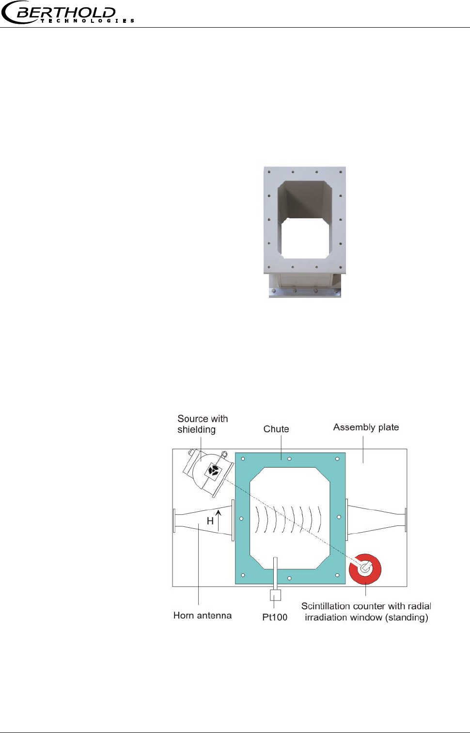
3.4.4 Measuring Chute
For bulk material Berthold Technologies delivers a measuring chute
complete with mounting plate and brackets for horn antennas,
scintillation counter and shielding containers. The chute is made of
plastic PP-H or PVDF.
Figure 3-14:
Measuring chute
made of plastic PP-H
The horn antennas, the scintillation counter with collimator and the
shielding container with source are mounted on the assembly
plate. The plastic chute is firmly connected to the assembly plate.
The assembly plate is already provided with all the necessary
mounting holes, so that the microwave and radiometric measuring
path can be aligned optimally, see Figure 3-15.
Figure 3-15:
Assembly plate
with chute,
horn antennas and
radiometric measuring
path
Chapter 3 System Description
30 MircoPolar Moist LB 568
3.4.5 High-frequency Cable
High-frequency cables (HF cable) are used to transmit the
microwave signals.
HF cables change their conductivity (for microwaves) depending on
the temperature. Therefore, they would create measurement
errors if the ambient temperature varies. This error is
compensated for by enabling the cable compensation. The
influences of the ambient temperature on the signal cable are
compensated for by means of the reference cable. To this end, the
sum of the reference cables is chosen just as long as the sum of
the measuring cables.
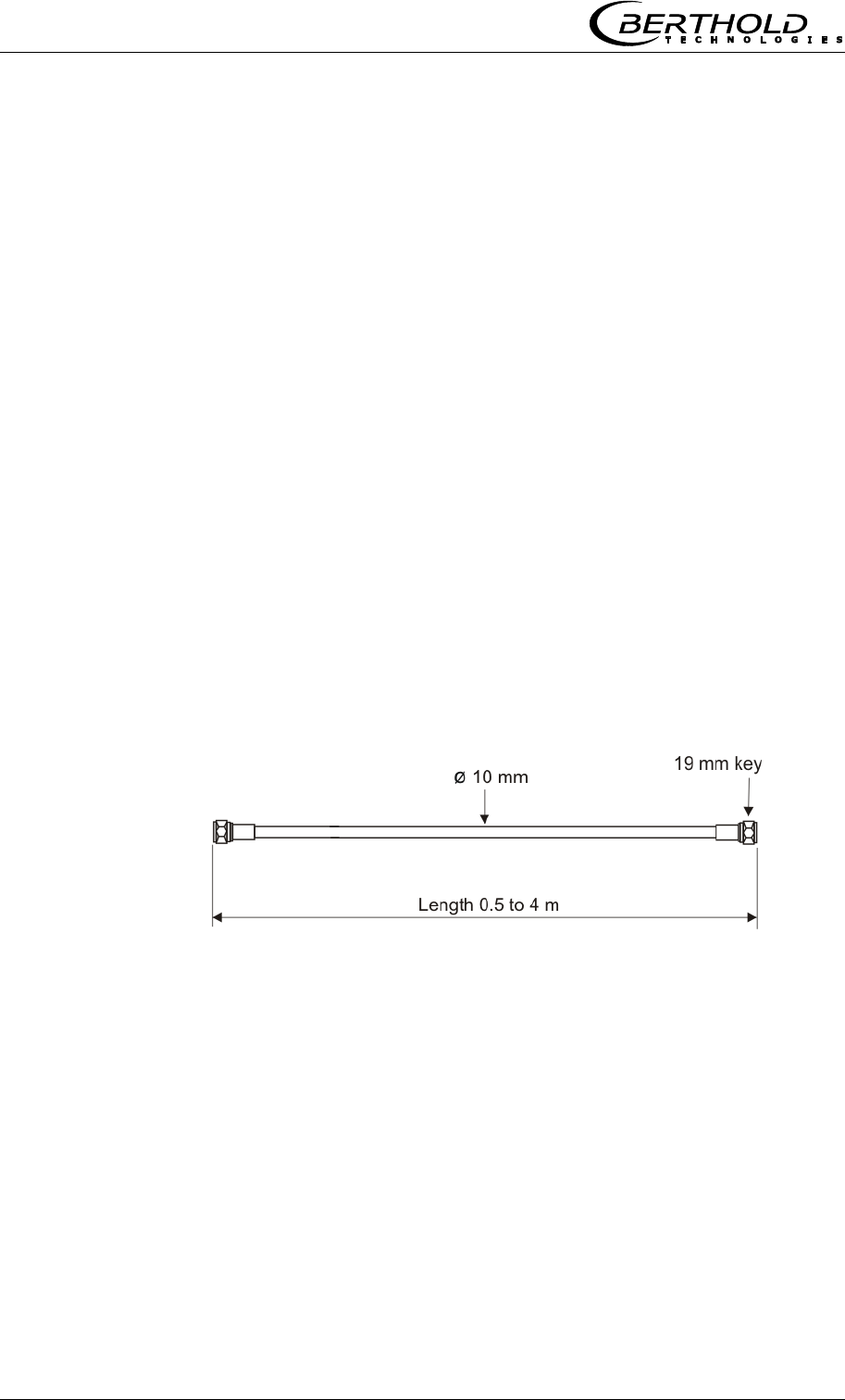
The HF cable is provided at the ends with an HF connector (N-
type). Available lengths: 0.5 to 4 m (in 0.5 m steps, see Figure 3-
16).
One HF cable (called measuring or antenna cable) connects the
evaluation unit with the antenna. A third HF cable serves as
reference line; its cable length corresponds to the sum of the
lengths of both antenna cables.
The shorter the cable connections between antennas and
evaluation unit, the better the stability of the measurement.
Figure 3-16:
Semi-rigid cable
For further technical data see chapter 6.5 Technical Data HF-Cable.

Chapter 3 System Description
MircoPolar Moist LB 568 31
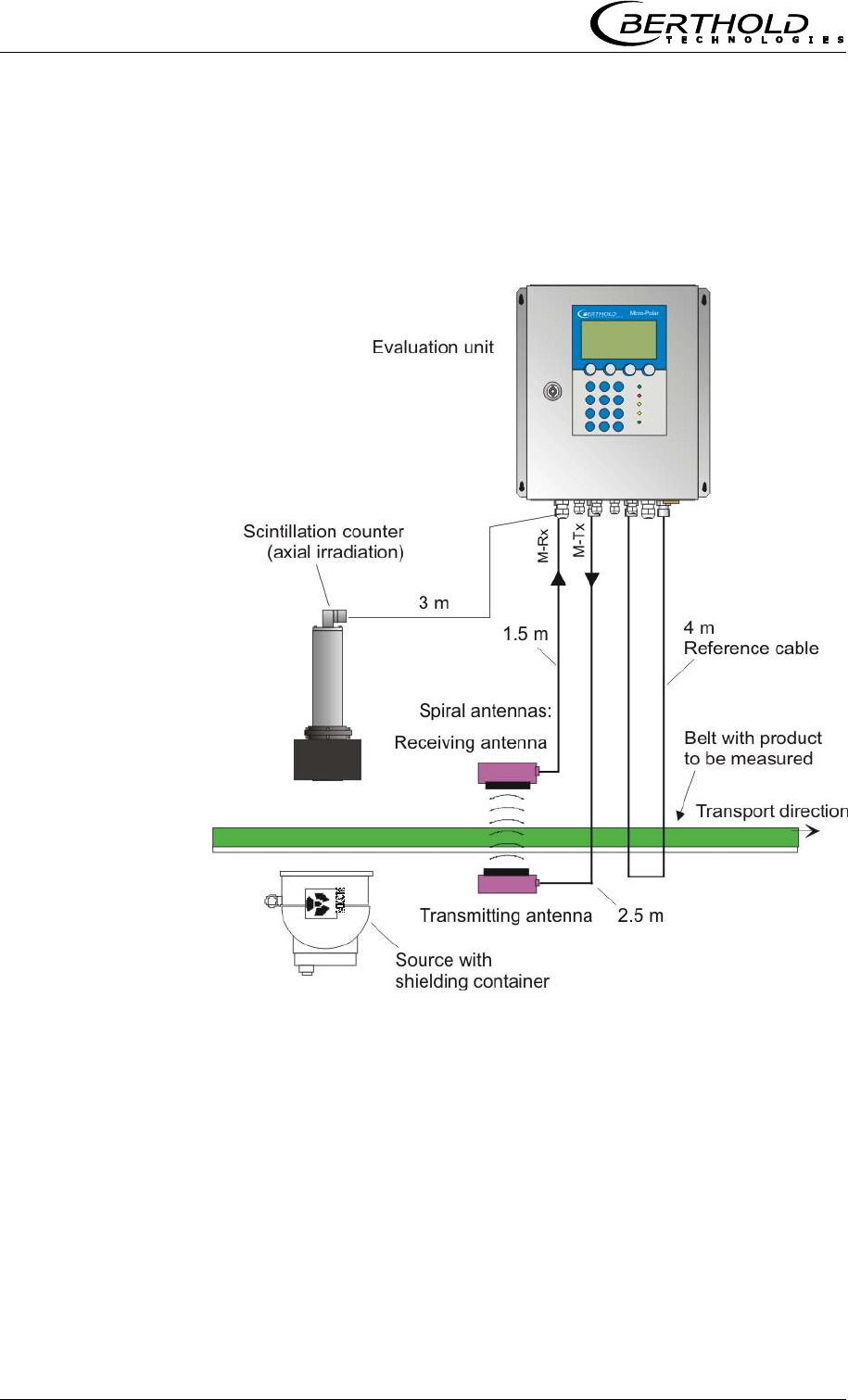
3.5 Conveyor Measurement Configuration
The antenna pair and the radiometric measuring path are
assembled in a stable frame. The evaluation unit is installed in the
direct vicinity of the horn antennas in order to limit the length of
the HF cables to max. 2 m each. See also Figure 3-17 and the
installation proposal in chapter 10.6 Installation Proposal on the
Conveyor Belt.
Figure 3-17:
Typical measurement
configuration on a
non-steel reinforced
conveyor belt.
With horn antennas and
radiometric
mass per unit area
measurement
(with example values).
Chapter 3 System Description
32 MircoPolar Moist LB 568
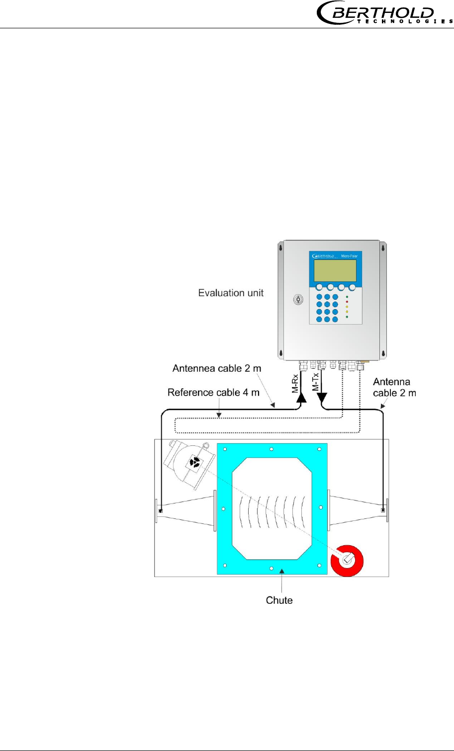
3.6 Chute Measurement Configuration
The measuring chute is installed directly in the product flow, or in
a bypass. Complete filling of the chute during the measurement
must be guaranteed. The antennas, the scintillation counter and
the source with the shielding container are mounted on the
mounting brackets provided on the measuring chute. The
evaluation unit is installed in the direct vicinity of the horn
antennas in order to limit the length of the HF cables to max. 2 m
each. See also Figure 3-18 and the installation proposal in chapter
10.7 Installation Proposal on the Measuring Chute.
Figure 3-18:
Typical measurement
configuration
on the measuring chute
with example values

Chapter 4 Getting Started
MircoPolar Moist LB 568 33
Chapter 4. Getting Started
4.1 Transport to the Installation Site
IMPORTANT Risk of damage!
System parts may get damaged during transportation!
Transport all components in their original packaging. Protect parts
against shocks. Especially the horn antenna must be protected
against mechanical shocks, as otherwise the coupling pins may
get bent and the function can be impaired severely.
After unpacking, make sure all parts listed on the packing list have
been delivered and show no sign of damage; if necessary, clean
these parts.
If you detect any damage, please notify the forwarder and the
manufacturer immediately.
The weight of the system components may exceed 30 kg,
depending on the version. We recommend, therefore, that you
wear safety boots.
4.2 Commissioning the Conveyor Belt
4.2.1 Components
The measurement setup on a conveyor belt basically comprises the
following components:
a pair of horn or spiral antennas
an evaluation unit
a scintillation counter with collimator and connection cable
a source with shielding container
a set of HF cables
The MircoPolar Moist is usually delivered with radiometric mass per
unit area measurement for compensation. If the bulk density is
constant, optional compensations are possible, e.g. by a layer
thickness or weight measurement. Details see chapter 7. Other
Possibilities for Compensation.
Chapter 4 Getting Started
34 MircoPolar Moist LB 568
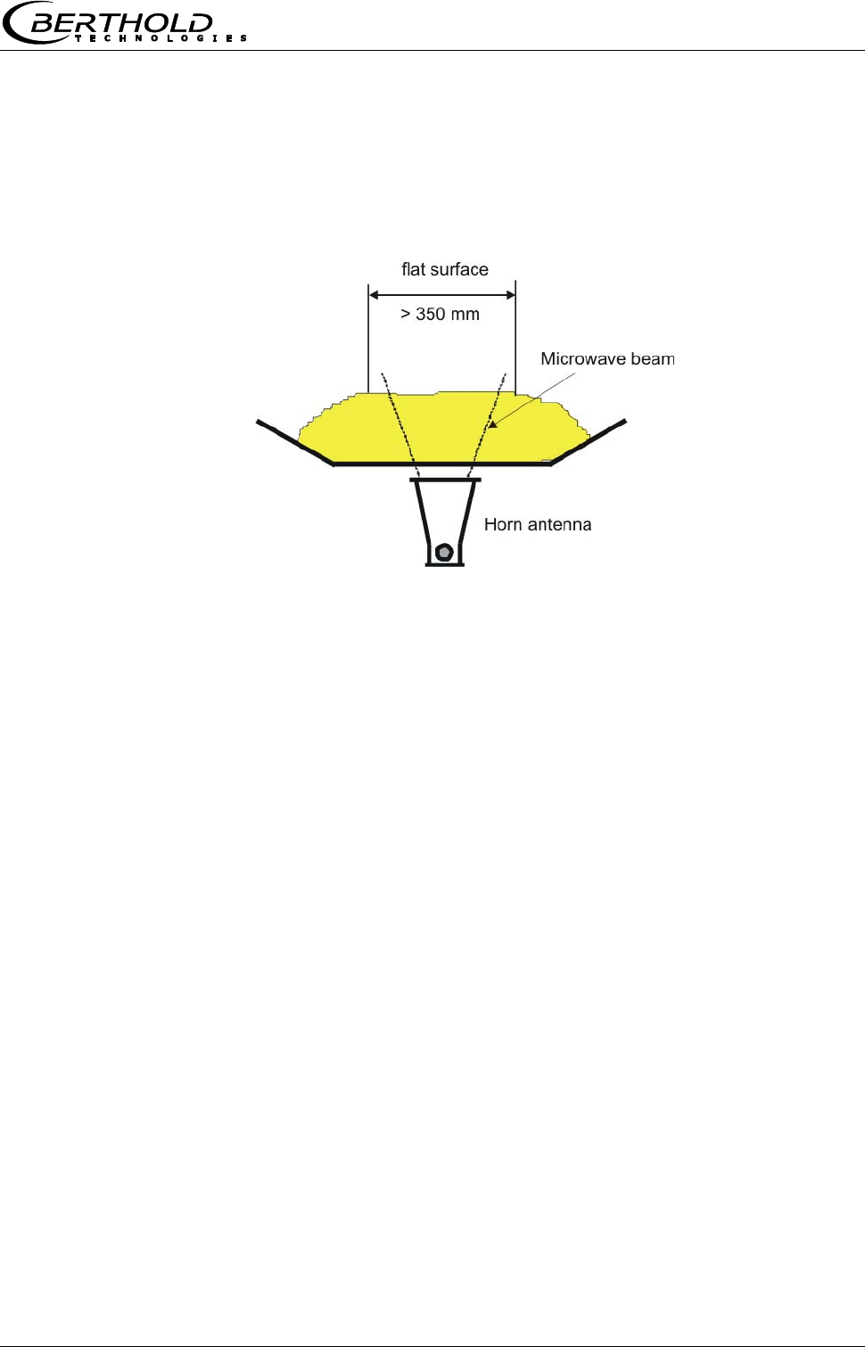
4.2.2 Measuring Geometry and Measuring
Conditions
1. Measuring condition: Required material profile
The product surface must be flat over a width of at least
350 mm (see Fig. 4-1). No gaps or slots in the product. This is
absolutely essential to ensure that the microwave irradiation field
always sees the same product density and the compensation
measurement correlates with the microwave measurement.
Figure 4-1:
Flat surface
in the beam range
Figure 4-2:
Example 1:
The microwaves
continuously irradiate a
different material layer.
Figure 4-3:
Example 2:
Compensation and
microwave measurement
do not see the same
material layer; therefore,
both measurements do
not correlate with each
other.
Chapter 4 Getting Started
MircoPolar Moist LB 568 35
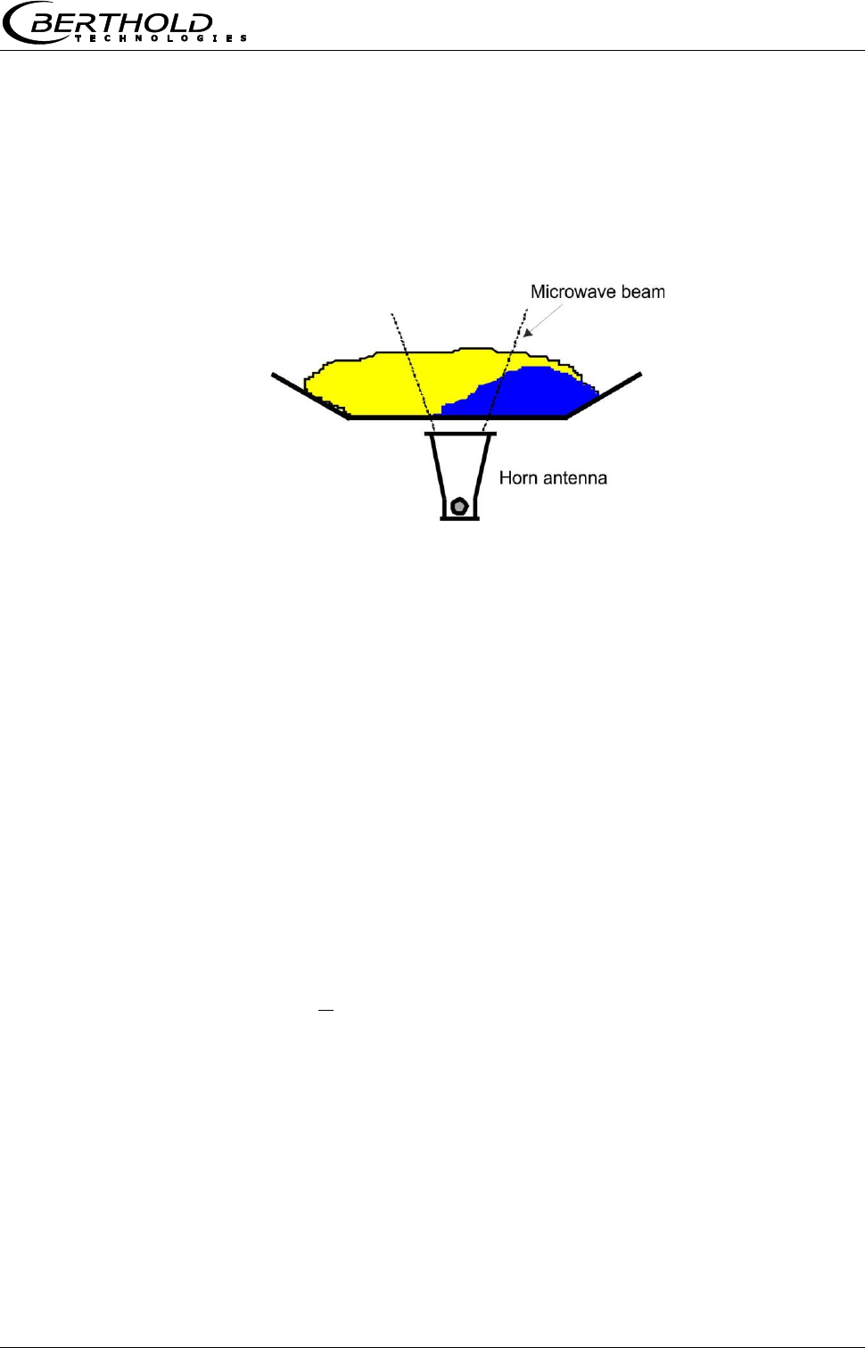
2. Measuring condition: Homogeneous load on the belt
The product must be homogeneous. If the product is not mixed or
asymmetrical on the belt, the moisture reading is not
representative and the sampling (e.g. for calibration) may possibly
be incorrect, see Fig. 4-4.
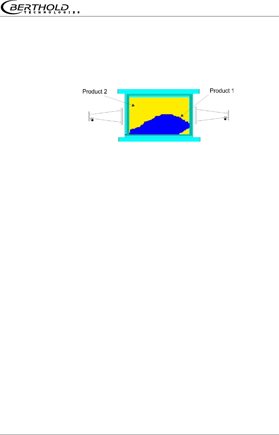
Figure 4-4:
Two different products
(e.g. due to different
moistures), not mixed
and filled asymmetrically.
3. Measuring condition: electrically conductive materials
No metals or other conductive materials must be located
between transmitting and receiving antennas (in the radiation
field).
A special case are steel reinforced conveyor belts, see the
following chapters.
4. Measuring condition: Minimum load
The minimum load on the conveyor belt is dependent on the
product composition and the material structure. In a first
approximation, the minimum material thickness can be specified
as follows:
4
min d
Eq. 4-1
Where:
dmin = minimum material thickness [cm]
= bulk density [g/cm3]
Chapter 4 Getting Started
36 MircoPolar Moist LB 568
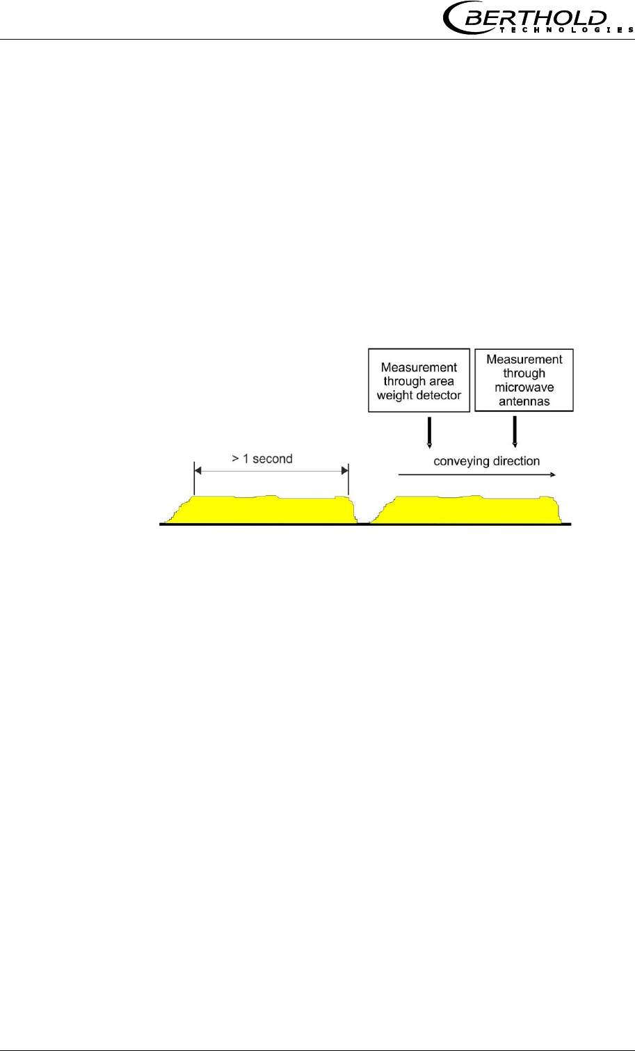
5. Measuring condition: Synchronous belt load
The loading compensation can only function correctly if the
microwave and the compensation measurement measure the same
product. Because only then the ratio of the two signals is correct
(see Eq. 3.1 in chapter 3.2 Measurement Calculation).
To this end, the product will first pass through the radiometric
measuring path before it reaches the microwave measuring path.
Furthermore, the belt load for a period of at least 1 second must
remain the same, see Figure 4-5.
Figure 4-5:
Correlate the same
belt load
More synchronization options are available for the alternative
compensation options (layer thickness sensor / belt weigher), see
chapter 7.3 Synchronization of the Current Input Signals.

Chapter 4 Getting Started
MircoPolar Moist LB 568 37
4.2.3 Installation of the Horn Antennas
The installation is done as shown in our example in Figure 3-17 or
the installation proposal in chapter 10.6.
A stable bracket must be provided. The accessories include a
bracket that allows variable orientation.
Setup of the Horn Antennas
Install both horn antennas in diametrically opposite locations
Transmitter and receiver must always have the same
polarization; the couplers must always point in the same
direction.
Typical distances between the antennas are 30 to 80 cm, but
may be up to 1 or 2 m.
The coupler should always face the material flow, because then
the waves are not deflected so much by the material flow.
The transmitting antenna must be installed below, the
receiving antenna, above the conveyor belt.
When transmitting the upper and lower belt, you should allow
for incorrect measurements caused by the geometry. Sufficient
room for the horn antennas should be available below the
upper belt. If necessary, a belt deflection has to be carried out,
or you have to check if spiral antennas are better suited.
Select the installation site of the horn antennas such that they
will not be affected by dirt on the radiation exit window.
Install the reference cable parallel to the signal cables. Its
length corresponds to the sum of both signal cables.
Install the antennas as far away as possible from the rollers or
other metallic objects.
The supplied HF cable can be bent depending on your
installation situation (min. bending radius 10 cm). Fix the
cables to prevent them from slipping. It is not permitted to
change the cable lengths or to use other cables.
In wet areas the cable connection always have to face down.
Make sure that no humidity can penetrate. If necessary, you
have to seal the HF-connection by taking suitable provisions.
Chapter 4 Getting Started
38 MircoPolar Moist LB 568
To ensure a satisfactory measurement on conveyor belts, the
material layer should be plane-parallel with the belt. With bulk
goods, one can achieve this smoothing effect quite easily, for
example, by dragging a hinge-mounted plate over the material
surface. The same effect is obtained with a free-sliding ski
moving through parallel guide rods over the material surface.
Especially for grain sizes above 10 mm, the ski is superior to
the mobile plate. Experience shows that a fairly smooth surface
and homogeneous layer will be obtained only when the
minimum layer thickness is at least three times as high as the
maximum grain size. For fine-grained materials we recommend
using a "plow" to smooth the material surface without
significantly changing the bulk density, especially if no bulk
density or mass per unit area measurement is available
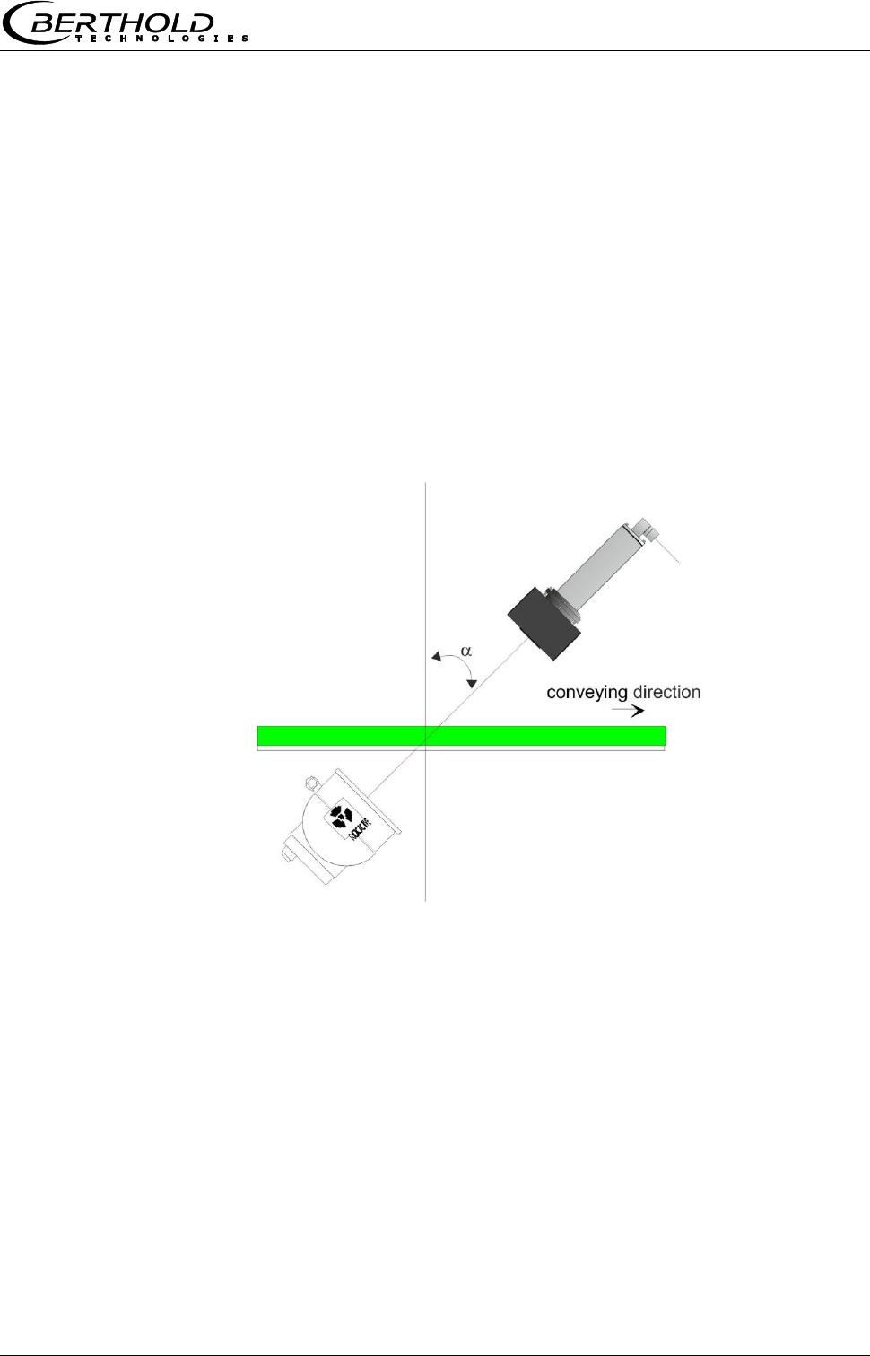
Exception: Oblique transmission
Typically, the horn antennas and the radiometric measuring path
are installed at a 90° angle to the material flow. Whether oblique
transmission is necessary and in which angle the antennas should
be mounted has to be clarified before planning the project. The
angle (see Fig. 4-6) will be specified by Berthold Technologies.
Figure 4-6:
Setup for
oblique transmission
The angle will be defined
by Berthold Technologies
In case of strong reflection, the interference of the reflected wave
can be reduced through oblique transmission.
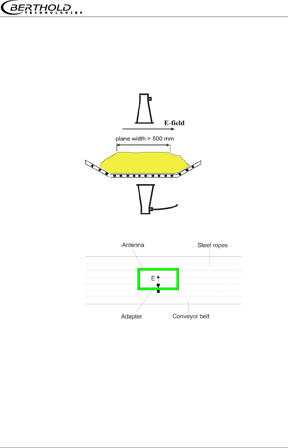
Exception: Steel-wire reinforced conveyor belt
If the conveyor belt is reinforced by metal ropes in the conveying
direction, the antennas have to be mounted such that the electric
field (E) runs at a 90° angle to the ropes. The connection socket of
the antenna cable faces the same direction as the electric field, see
Fig. 4-7 and 4-8.
Microwaves can irradiate conveyor belts with parallel metal wires
or rods only if the horn antennas are oriented correctly.
Chapter 4 Getting Started
MircoPolar Moist LB 568 39
Please contact the manufacturer and state the diameter of the
steel ropes and their distance. Make sure that the belt itself is not
made of conductive rubber (anti-static through additional
graphite).
The surface of the product must be flat over a stretch of at least
500 mm (instead of 350 mm as in a regular configuration).
Figure 4-7:
Setup of the
horn antennas with
steel-reinforced
conveyor belt
Figure 4-8:
Alignment of the antenna
in the case of parallel
running steel ropes
In contrast to the recommended configuration without steel-
reinforced belts, here the antennas have to be turned by 90° so
that the cables come from the side, instead of running parallel to
the conveying direction.
Chapter 4 Getting Started
40 MircoPolar Moist LB 568
4.2.4 Installation of the Spiral Antennas
The installation is done as shown in our example in Figure 4-9.
Stable brackets must be provided.
Figure 4-9:
Measurement setup
on a conveyor belt
with spiral antennas
(with example values)

Chapter 4 Getting Started
MircoPolar Moist LB 568 41
Setup of the Spiral Antennas
Install both antennas in diametrically opposite locations
Typical antenna distances are approx. 10 to 70 cm.
The transmitting antenna must be installed below, the
receiving antenna, above the conveyor belt.
The connection may face any direction.
The spiral antennas must be installed at a 90° angle to the
material.
The spiral antennas should be installed at least 10 cm above
the max. loading level.
Select the installation site of the spiral antennas such that they
will not be affected by dirt.
The length of the reference path normally corresponds to the
sum of the length of both antenna cables and has to follow the
same way as long as possible.
The phase measurement is usually used in homogeneous
material. Under certain conditions, an attenuation
measurement may also be performed on inhomogeneous
material.
Note: Oblique transmission and irradiation of steel-reinforced belts
is not possible due to the circular polarization.
Chapter 4 Getting Started
42 MircoPolar Moist LB 568
4.2.5 Installation of the Radiometric Measuring
Path
The radiometric measuring path consists of the radiation source in
a lockable shielding container and the scintillation counter with
3 m long connection cable (connection to the R-board in the
evaluation unit).
Check if the shielding container is closed before you begin the
installation.
Radioactivity!
Installation and commissioning of radiometric measuring systems
may be carried out only by persons who have been instructed
adequately by professional personnel!
Work is carried out under the guidance and supervision of the
Radiation Safety Officer. Make sure that the lock of the shielding is
closed.
To do this, set the lever of the shielding container LB 744X clearly
to the "CLOSED" position. Set the locking device to the "OPEN"
position only for commissioning.
The radiation source and the scintillation detector must be exactly
aligned. A suitable bracket is available for detector installation,
allowing subsequent adjustment of the alignment. The fine position
adjustment is done later by shifting the detector until the
maximum count rate (signal intensity picked up by the detector) is
reached. See also Figure 3-17 and the installation proposal in
chapter 10.6 Installation Proposal on the Conveyor Belt.
The mounting frame must be so sturdy that any subsequent
shifting of both components relative to each other is ruled out.
This would alter the geometry of the measurement and cause
measuring errors. Depending on the version, the detector is
designed for frontal or radial irradiation.
The shielding container should be installed as close as possible to
the conveyor belt. If no design documentation is available, a
minimum distance of 5 cm should not be exceeded for radiation
protection reasons. The conveyor belt must not touch the shielding
container. A special mounting plate allows adjustment of the
distance in steps of 35 mm.
The radiometric measuring path can be installed directly next to
the microwave measuring path. Even a crossover of gamma
radiation and microwaves is uncritical. A mutual interference will
not occur.
Chapter 4 Getting Started
MircoPolar Moist LB 568 43
In order not to limit the lifetime of the detector, the transmission
of excessive vibration and temperatures above 50°C must be
avoided by taking appropriate measures. For outdoor operation,
the detector should be protected from direct sunlight and rain by a
canopy. Accessories for the protection hood, see chapter 6.3
Technical Data Radiometric Mass per Unit Area Measurement.
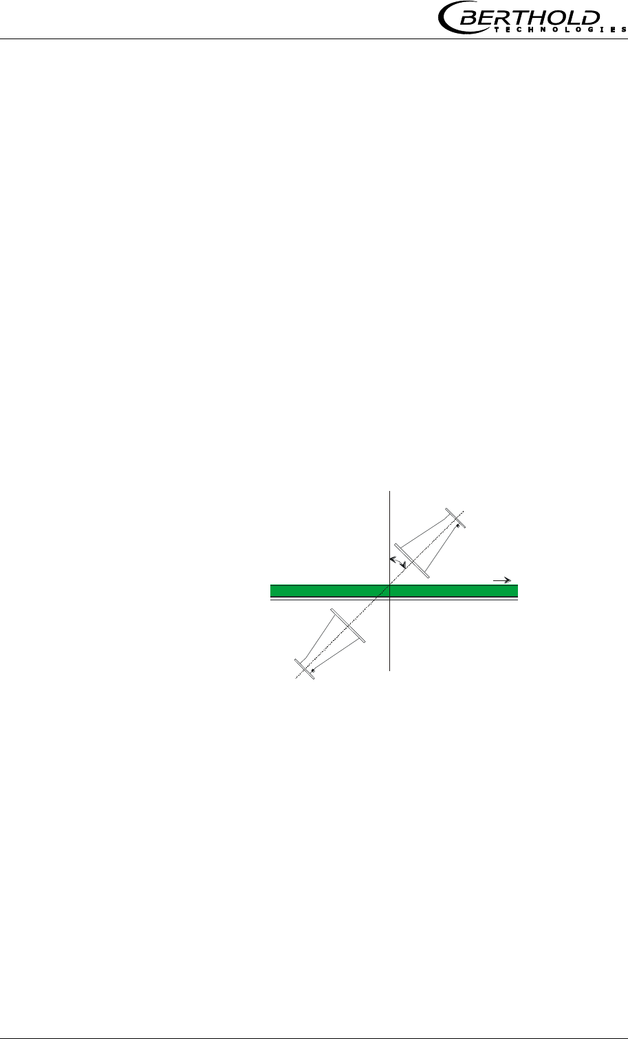
Exception: Oblique transmission
The transmission angle of the radiometric mass per unit area
measurement, see Figure 4-10, corresponds to the transmission
angle of the microwave antennas, see chapter 4.2.3 Installation of
the Horn Antennas. This ensures that both measurements transmit
the same layer thickness.
Figure 4-10:
Chapter 4 Getting Started
44 MircoPolar Moist LB 568
Exception: Steel-wire reinforced conveyor belt
If the conveyor belt is reinforced by metal ropes in the feed
direction, the positions of source and detectors have to be
exchanged (see Figure 4-11). The source with shielding container
is then placed above and the scintillation counter below the
conveyor belt.
If the distance between the upper and lower belt is too small for a
detector with an axial radiation, one can use the detector with side
window.
Figure 4-11:
4.2.6 Installation of the Evaluation Unit
For installation of the evaluation unit please keep in mind:
Position the evaluation unit depending on the length of the HF
cable in the vicinity of the microwave probe. The typical
distance between evaluation unit and flow cell is about 2 m.
The evaluation unit has to be protected against vibrations.
For instrument installation you should foresee a cutoff device to
allow easy and quick disconnection of the device from the
power supply.
For outdoor operation, the evaluation unit has to be protected
against direct sunlight and rain, for example by a suitable
canopy.

Chapter 4 Getting Started
MircoPolar Moist LB 568 45
4.2.7 Connecting the HF Cable
Connect the horn/spiral antennas and the evaluation unit (sockets
M-Tx and M-Rx) with the antenna cables. The transmitting antenna
is connected to M-Tx below the belt, and the receiving antenna to
M-Rx above the belt.
Connect a reference cable to the reference sockets of the
evaluation unit (R-Tx and R-Rx). The reference cable should have
the same characteristics and if possible the same length as the
total of both antenna cables.
When tightening the connector screw connection (19 mm screw
nut), make sure that the connector is not twisted on the cable. If
the connector is twisted relative to the cable, the shielding may
get damaged and this could result in a bad electrical contact and
bad sealing.
Hand tighten all screwed connections of the HF cable (2 Nm = 0.2
KG/m)! Before tightening, carefully screw on the cable by hand.
Caution! Threaded joint jams easily.
Install the signal and reference cable in the same manner (if
possible, parallel), so they are exposed to the same temperature
(temperature compensation of ambient temperature on the
antenna cable; this ensures long-term stability).
Fix the antenna and reference cable after you have installed them.
IMPORTANT
A steel pipe may protect the cable and keep signal and reference
cable on the same temperature for an effective temperature
compensation.
Kinked cables falsify the results and make the cable useless. The
bending radius should not be less than 100 mm.
Occasionally you should check if the screwed connection is still
properly tightened. If the installation is exposed to vibrations, the
screwed connection may come loose and this may result in
inaccurate measurements or corrosion of the connections.
As long as the cables are not connected, the coaxial sockets have
to be covered immediately with plastic caps and the cable
connectors have to be protected by suitable provisions against
moisture and dirt.

Chapter 4 Getting Started
46 MircoPolar Moist LB 568
4.3 Commissioning the Chute
The moisture measurement on a chute is done using a fully
assembled measurement configuration with horn antennas and
radiometric measuring path. See also Figure 3-19 Typical
measurement setup.
4.3.1 Components
The measurement setup on a measuring chute comprises the
following components:
a pair of horn antennas
a measuring chute including assembly plate and brackets for
horn antennas, scintillation counters and shielding containers
an evaluation unit
two HF antenna cables, one HF reference cable and two HF
angle connectors
4.3.2 Measuring Geometry and Measuring
Conditions
1. Measuring condition: electrically conductive materials
No metals or other materials with high conductivity must be
located between transmitting and receiving antennas (in the
radiation field). Measuring pipes or chutes must also not be made
of conductive material; otherwise, they have to be provided with
an entrance window made of plastic, glass or ceramics. The
standard dimensions of these entrance windows have to be chosen
with regard to the antenna distance; for standard applications they
have to be at least 15 x 15 cm up to 30 x 30 cm.
2. Measuring condition: Filling the chute
The bulk good has to be conveyed evenly through the measuring
chute and it has to be ensured that the chute is completely filled
for the measurement. In some cases, it is advisable to accumulate
the product, for example by using a slider installed below the
chute.
Chapter 4 Getting Started
MircoPolar Moist LB 568 47
3. Measuring condition: Homogeneous filling
The product must be homogeneous. If the product is not mixed or
asymmetrical in the chute, then the moisture reading is not
representative and the sampling (e.g. for calibration) can be
incorrect, see Fig. 4-12.
Figure 4-12:
Two different products
(e.g. through different
moistures) cannot be
mixed and filled
asymmetrically.
4.3.3 Installation
The horn antennas, the scintillation counter and the source with
shielding container are mounted with their respective brackets at
the measuring chute, typically on the mounting plate provided by
Berthold Technologies, see chapter 10.7 Installation Proposal
Measuring Chute.
The measuring chute is installed into the conveyor flow at a
suitable location. There must be no tapering of the chute and no
installations at least 400 mm before and behind the measuring
chute. In individual cases, these inlet and outlet sections can be
shortened; this is planned in the project design phase.
Assemble the components as shown in the dimensional drawing in
chapter 10.7 Installation Proposal Measuring Chute. All mounting
holes for the brackets and the measuring chute are available on
the mounting plate so that the measuring paths will be perfectly
aligned.
Protect the antennas against dust and dirt. Install the measuring
chute to your conveyor system such that you are able to reach all
parts of the measuring chute easily. Provide for a stable and
vibration-free mounting of the assembly plates. A material
sampling location should be foreseen in the vicinity of the
measuring chute for the necessary calibration.
If a PT100 is used, it should be oriented in the direction of the H-
field, see Figure 3-15 in chapter 3.4.4 The Measuring Chute.
The connections of the horn antennas should preferably face down,
so that they are better protected.

Chapter 4 Getting Started
48 MircoPolar Moist LB 568
Important: Bulk good has to be conveyed evenly through the
measuring chute, and it has to be ensured that the chute is filled
completely for the measurement.
Radioactivity!
Installation and commissioning of radiometric measuring systems
may be carried out only by persons who have been instructed
adequately by professional personnel!
Work is carried out under the guidance and supervision of the
Radiation Safety Officer. Make sure that the lock of the shielding is
closed.
4.3.4 Installation of the Evaluation Unit
Installation of the evaluation unit as described in chapter 4.2.6.
4.3.5 Connecting the HF Cable
Installation of the evaluation unit as described in chapter 4.2.7.
The two HF angle connectors can be used for the connection of the
HF cable to the horn antenna. The length of cable between the
antenna and evaluation unit may possibly be shortened.

Chapter 4 Getting Started
MircoPolar Moist LB 568 49
4.4 Connecting the Evaluation Unit
Electrical shock hazards
Disconnect power to ensure that contact with live part is avoided
during installation and when servicing.
Turn off power supply before opening the instrument. Work on
open and live instruments is prohibited.
Connect all desired input and output signals to the terminal
strip as shown on the following pages. Use the M feed-through
to keep the degree of protection.
Check if the voltage indicated on the type plate matches your
local supply voltage.
Connect the line cable to the terminals 3(L1), 2(N) and 1(PE).
Check if the test switch (mains interruption) is in position "ON"
(see Fig. 5-1).
Close the instrument housing and turn on the power supply.
Caution! Possible hazard, property damage!
Device type LB 568-02 MircoPolar Moist (ID no. 41990-02)
If the 24 V DC auxiliary energy is connected, the + and – poles
must be connected correctly. There is no reverse voltage
protection!
The line cross-section for power supply must be at least 1.0 mm2.
Chapter 4 Getting Started
50 MircoPolar Moist LB 568
4.4.1 Pin Configuration of the Connector Strip
On the connector strip of the evaluation unit you find the following
connections:
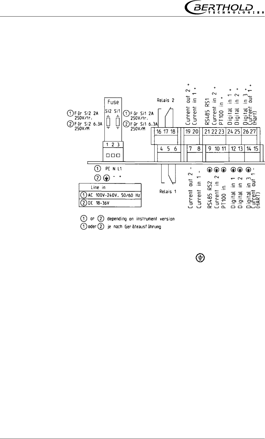
Figure 4-13:
Wiring diagram LB 568
Mains connection:
Terminals 3 (L1, +), 2 (N, -) and 1 (PE, )
Depending on instrument version, see type label on the outer wall
of the housing.
1.) 100 - 240 V AC, 50/60 Hz
2.) 18 - 36 V DC, no reverse voltage protection
Current input no. 1 (terminals 20+ and 8-), insulated
Input as 0/4 - 20 mA signal. e.g. for temperature compensation or
reference signal recording.
Current input no. 2 (terminals 22+ and 10-), not insulated
Input as 0/4 - 20 mA signal. e.g. for temperature compensation or
reference signal recording.
Current output no. 1 (terminals 27+ and 15-), insulated
Output as 4 - 20 mA signal. Output options: moisture content /
concentrations (1 / 2), current inputs signals (1 / 2), PT100 signal
and mass per unit area

Chapter 4 Getting Started
MircoPolar Moist LB 568 51
Current output no. 2 (terminals 19+ and 7-), insulated
Output as 0/4 - 20 mA signal. Output options: See current output
no. 1
PT100 (terminals 23+ and 11-)
Connection for temperature measurement
Digital input 1: DI1 (terminals 24+ and 12-)
Configuration options:
No function
Measurement: Start (closed) and stop (open)
Digital input 2: DI2 (terminals 25+ and 13-)
Configuration options:
No function
Average value: hold (closed) and continue averaging (open)
Product selection: product 1 (open) and product 2 (closed)
Digital input 3: DI3 (terminals 26+ and 14-)
Configuration options:
No function
Start sampling, open: no action, closed: unique measurement
starts
Product selection
Relay 1: (terminals 4, 5 and 6) and
Relay 2: (terminals 16, 17 and 18)
Change-over contacts (SPDT), insulated, configuration option:
no function
error message
stop measurement
limit value min. and max.
RS485 interface (terminals 21 (RS1) and 9 (RS2))
Occupied by the radiometry board
Chapter 4 Getting Started
52 MircoPolar Moist LB 568
RS232 interface (on instrument underside)
9-pole Sub D-connector. Serial data interface for output of the live
data (all readings for every sweep (measuring cycle), the minutes
and data logs.
Data format: Data transfer rate 38400 baud, 8 data bits, 1 stop
bit, no parity, no handshake
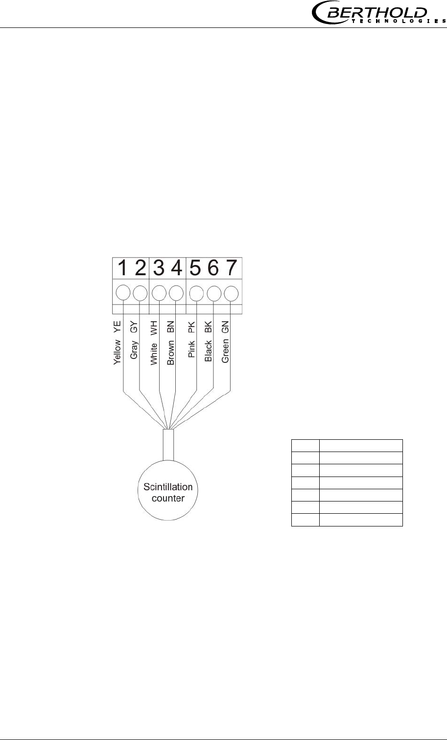
4.4.2 Connecting the Scintillation Counter
The scintillation counter is connected to the terminal strip on the
radiometry board, see Figure 4-14. The connecting wires can be
distinguished by the cable color.
Figure 4-14:
Wiring diagram
Scintillation counter
The assignment of the terminal
strip is as follows:
1
Detector +
2
Detector -
3
RS485-A
4
RS485-B
5
+ 24 V
6
Screen
7
24 V GND
Chapter 4 Getting Started
MircoPolar Moist LB 568 53
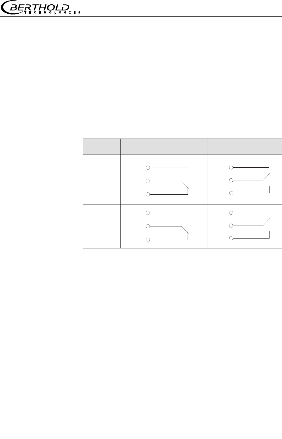
4.4.3 Digital Outputs, Relay
The status of the measurement is output via two relays:
Error
Alarm (alarm min. and max.)
measurement stopped
The respective switching status is also signaled via LED’s on the
front panel (LED’s signal 1 and 2).
Relay no.
Error, alarm, measurement
stopped, currentless state
Normal
1
2
The relays with changeover contacts can either be operated as
make contact, terminals 4 & 5 (open at error, alarm ...) or as
break contact, terminals 5 & 6 (closed at error, alarm ...).
com
4
5
6
com
16
17
18
com
4
6
5
com
16
18
17

Chapter 5 Service Instructions
54 MircoPolar Moist LB 568
Chapter 5. Service Instructions
5.1 General Information
A malfunction of the measuring system is not always due to a
defect in the instrument. Often the error is caused by incorrect
operation, wrong installation, or irregularities in the product being
measured. If a malfunction occurs, anyway, the measuring system
helps you to identify and eliminate errors by displaying error
messages on the LCD, indicating operator errors and defects of the
electronics.
Usually, faulty modules of the evaluation unit cannot be repaired
but have to be replaced. The microwave module is fixed with
screws to a shielding cover and must not be opened.
The locking mechanism of the shielding container has to work. In
case of malfunctions or sluggishness, please contact the Berthold
Technologies service.
5.2 Parts Subject to Wear
The evaluation unit does not include any parts that are subject to
wear or components requiring any special maintenance.
Depending on the material to be measured, the measuring chute
may be subject to wear over time; therefore, you should check it
at regular intervals. The measuring chute must be replaced if
required due to heavy wear.
5.3 Instrument Cleaning
Clean all system components only with a moistened cloth without
chemical cleaning agent.
The horn and spiral antennas do not require any special
maintenance; however, the radiation exit window should always be
kept clean.
5.4 Battery
If the measuring system LB 568 is without power supply (power
failure or disconnected from mains), the system clock is supplied
with power via the Lithium battery on the motherboard.
If the battery voltage is no longer sufficient, the error message
CODE 14 "Battery voltage" is displayed after restart of the
evaluation unit. After acknowledging the error message the device
Chapter 5 Service Instructions
MircoPolar Moist LB 568 55
will continue to function correctly, but the date and time should be
checked and corrected if necessary. We recommend changing the
batteries immediately.
After battery replacement and if the zero count rate is set (I0, for
the radiometric mass per unit area measurement), the error
message CODE 105 "Decay compensation failed: Enter date/time"
is displayed. Please check and correct the date and time so that
the decay compensation can work properly.
The service life of the battery, even under continuous load, is at
least 8 years. Replace the fuses only if the instrument is
disconnected from mains.
Battery type: 3 Volt lithium cell (round cell battery), type CR2032
(ID no. 17391)
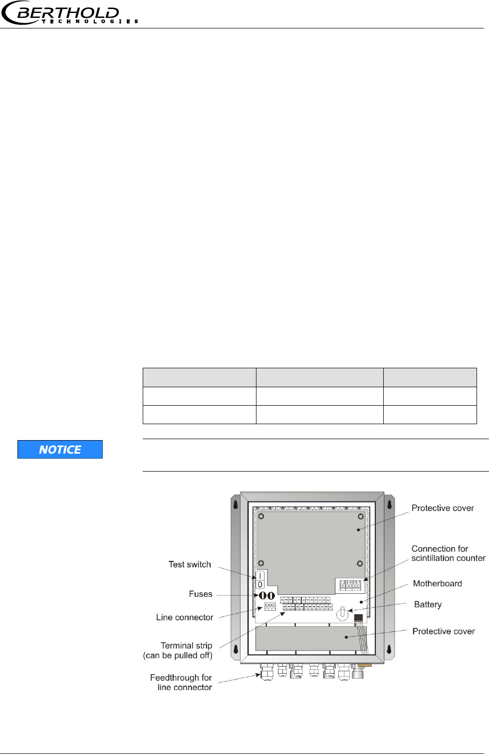
5.5 Fuse Replacement
The mains fuses of the LB 568 are located in the wall housing.
Replace the fuses only if the instrument is disconnected from
mains.
Use only fuses with correct rating:
Device version
Fuse values
ID no.
100 ... 240 V AC
2 x 2.0 A / 250 V / T
4403
18 ... 36 V DC
2 x 6.3 A /250 V / M
4408
Spare fuses must match the rating specified by the device
manufacturer. Short-circuiting or manipulation is not permitted.
Figure 5-1:
Look inside the
instrument LB 568

Chapter 6 Technical Data
56 MircoPolar Moist LB 568
Chapter 6. Technical Data
General Specifications
Method
Microwave transmission measurement
Transmission
power
< 10 μW (< -20 dBm),
Coaxial line power
Applications
Concentration / moisture measurement on
conveyor belts and in chutes.
6.1 Technical Data Evaluation Unit
Evaluation unit
Housing
Wall housing made of stainless steel, see
dimensional drawing in chapter 10.1
HxWxD: 400x338x170 mm,
Protection type
IP 65
Weight
approx. 8.0 kg
Ambient conditions
during operation
Relative humidity: max. 80% in the housing
Altitude: max. 2000 m
-20...45 °C ( 253 K ...318 K ), no
condensation
Ambient conditions
during storage
-20...70 °C ( 253 K ...343 K ), no
condensation
Relative humidity: max. 80 %
Achievable
accuracy
0.1 weight % (standard deviation)
depending on product and process
Display
Dot matrix LC display, 114 mm x 64 mm, 240
x 128 pixels, with back-lighting, automatic
contrast setting
Keyboard
Freely accessible foil keypad, light-stable and
weatherproof: alphanumeric keyboard and 4
softkeys (software-assigned buttons)

Chapter 6 Technical Data
MircoPolar Moist LB 568 57
Power supply
Depending on instrument version:
1.) 100...240 V AC, 50/60 Hz
2.) 24 V DC: 18 ... 36 V,
no reverse voltage protection
Power consumption
max. (48/60) VA (AC/DC),
depending on configuration
Fuses
2 x 250 V / 2.0 A / slow-blow at 100…240 V AC
ID no. 4403
or
2 x 250 V / 6.3 A / M at 18…36 V DC;
ID no. 4408
Battery type
3 V Lithium button cell, type CR2032
ID no. 17391
Measured value
e.g. concentration, moisture content
Inputs and Outputs
Cable cross-section
min. 1.0 mm² (mains supply)
Cable feed-through
2 x M20x1.5 for cable 5...14 mm (depending
on application)
4 x M16x1.5 for cable 5 ...8 mm (depending
on application)
Sensor connection
Inputs and outputs for signal and reference
channel, 50 N-socket
HF-cable HF-cable
Different cable lengths and versions: 50 ;
both sides with 4 N-connectors
Current input
2 x current input 0/4 ...20 mA, ohmic
resistance 50 , 1x insulated, 1x instrument
grounded
e.g. for temperature compensation
Current output
Current Output 1: 4...20 mA, ohmic
resistance max. 800 , insulated
Current output 2: 0/4...20 mA, ohmic
resistance max. 800 , insulated
e.g. for result or temperature output
PT-100 connection
Measuring range: -50...200 °C (223...473 K);
measurement tolerance: < 0.4 °C

Chapter 6 Technical Data
58 MircoPolar Moist LB 568
Digital input
3 x digital inputs (DI1..3), for floating
connectors
Configuration options:
DI1: none, measurement start/stop
DI2: none, measurement hold, product selection
DI3: none, sampling, product selection
Function description:
1. Measurement (Start/Stop)
open: measurement stopped
closed: measurement started and/or
measurement running
2. Hold measurement
open: measurement running
closed: measurement stopped, i.e.
average values and current output
are held
3. Product selection via a DI:
open: Product 1 (P1), closed: P2;
Product selection via two DI’s:
DI2 & DI3 open: P1
DI2 closed & DI3 open: P2
DI2 open & DI3 closed: P3
DI2 & DI3 closed: P4
4. Start sampling: open: no actions, closed:
single measurement starts
Relay outputs
2 x relays (SPDT), insulated
Configuration options:
- Collective failure message
- Stop measurement
- Limit value (min. and max.)
Load capacity:
AC: max. 400 VA
DC: max. 90 W
AC / DC: max. 250V, max. 2A, non-inductive
150V: voltage must be grounded
The cable and the insulation of the cables to
be connected at these connections must
comply with a power supply cable.
Restrictions for 24 V DC (18…36 V) mains
supply, if the ground conductor is not
connected to terminal 1 (PE):
AC: max. 50 V
DC: max. 70 V
Serial interfaces
RS232 on the device underside
RS485 occupied by the radiometry board
Data format: 38400 Bd, no handshake, 8 data
bits, 1 stop bit, no parity

Chapter 6 Technical Data
MircoPolar Moist LB 568 59
6.2 Technical Data Horn and Spiral
Antennas
Horn antenna (ID no.: 10806)
Application
Used in pairs, for example on conveyor belts and
chutes for the moisture measurement in bulk
goods.
Material
Stainless steel, microwave window made of
Makrolon
Weight
1.4 kg
Temperature range
Ambient temperature: -20...60 °C (253...333 K)
Storage temperature: 10...80 °C (283...353 K)
Connection
1 x HF connections: N-connector, 50
Dimensions
See dimensional drawings in chapter 10.4.1
Accessories antenna fixture (ID no. : 10805)
Material
Galvanized steel
Weight
3.8 kg
Dimensions
See dimensional drawings in chapter 10.4.1
Spiral antenna (ID no. : 15394)
Application
Used in pairs, for example on conveyor belts and
chutes for the moisture measurement in bulk
goods.
Material
Stainless steel, plastic
Weight
0.4 kg
Temperature range
Ambient temperature: -20…60 °C (253...333 K)
Storage temperature: 10...80 °C (283...353 K)
Connection
1 x HF connections: N-connector, 50
Dimensions
See dimensional drawings in chapter 10.4.2

Chapter 6 Technical Data
60 MircoPolar Moist LB 568
6.3 Technical Data Radiometric Mass per
Unit Area Measurement
Scintillation counter
Versions
1. With axial collimator (Id. 56942), for frontal
irradiation
2. With radial collimator (Id. 56943), for radial
irradiation
Crystal
CsI 40 x 50
Material
Stainless steel
Collimator: Lead, painted steel
Protection type
IP 67
Weight
Without collimator: approx. 2 kg
With axial collimator: approx. 10.6 kg
With radial collimator: approx. 10 kg
Power supply
12...24 V DC, 1.2 W
Operating
temperature
-20...50 °C (253...323 K)
Storage
temperature
-20...60 °C (253...333 K)
Connection cable
3 m long, 7-wire, shielded (7 x 0.5 mm2),
cable connection angled 90°,
temperature range: -40…70 °C (233…343 K)
Dimensions
See dimensional drawings in chapter 10.5
Accessory mounting options
ID no.
Description
56860
Scintillation counter bracket, complete
Material: galvanized steel, plastic
Dimensional drawings in chapter 10.5
25668
Clamps (1 set = 2 clamps)

Chapter 6 Technical Data
MircoPolar Moist LB 568 61
Shielding for point sources (LB 744X)
ID no.:
Types:
37624
LB 7440-D-CR, internal parts made of stainless
steel
38040
LB 7440-DE-CR, stainless steel
38042
LB 7445-D-CR, internal parts made of stainless
steel, with leakage protection
38043
LB 7445-DE-CR, stainless steel, with leakage
protection
Shielding accessories
ID no.:
Types:
14716
Shielding bracket, complete for LB 7440 D
52752
Protective cover for shielding LB 7440/42/44
11213
Radiation sign (RADIOACTIVE), plastic
14658
Radiation sign (RADIOACTIVE), aluminum
Pneumatic shutter for shielding
ID no.:
Description
36119
Pneumatic shutter actuator with limit switch, IP 65
Data for pneumatic shutter actuator
Compressed air:
min. 4 x 10⁵ Pa (4 bar)
max. 4 x 10⁵ Pa (7 bar)
Connection: G 1/8
Air quality:
Clean as usual for pneumatic tools, oil-free
Temperature range:
-20…80 °C
Limit switch unit, signaling options for OPEN / CLOSE
Option
IP 65 2 contacts (OPEN/CLOSE) 48 V DC, 1A
Point source Cs-137
ID no.:
Made of stainless steel
54712-08
Pt. source Cs-137 370 MBq (10 mCi) - SSC-200
54712-12
Pt. source Cs-137 1110 MBq (30 mCi) - SSC-200
54712-13
Pt. source Cs-137 1850 MBq (50 mCi) - SSC-200
ID no.:
Made of titanium
54281-08
Pt. source Cs-137 370 MBq (10 mCi) – SSC-100
54281-12
Pt. source Cs-137 1110 MBq (30 mCi) – SSC-100
54281-13
Pt. source Cs-137 1850 MBq (50 mCi) – SSC-100

Chapter 6 Technical Data
62 MircoPolar Moist LB 568
6.4 Technical Data Measuring Chute
Measuring chute, complete
Application
For moisture and concentration determination in
bulk material.
Variants / Chute
material
1. Polypropylen homo polymer (PP-H)
ID no. 56855
2. Polyvinylidene fluoride (PVDF),
ID no. on request
Components
- Chute
- Mounting plate
- 4 brackets
- two RF angle connectors
- Fastening material
Weights
Only for the chute:
Version 1: approx. 10 Kg
Version 2: on request
Measuring chute, complete
Version 1: approx. 41 Kg
Version 2: on request
Temperature range
Environment: 0...50 °C (273...323 K)
Storage: 10...80 °C (283...353 K)
Product temperature:
Version 1: > 0...90 °C (273...363 K)
Version 2: > 0…140 °C (273 … 413 K)
Mounting plates,
brackets
Material: Stainless steel, galvanized steel
Dimensions
See dimensional drawings in chapter 10.7

Chapter 6 Technical Data
MircoPolar Moist LB 568 63
6.5 Technical Data HF-Cable
HF cable
Material
Cable sheath: Polyethylene (PE)
Protection type
IP 68 in the screwed on state
Temperature
Operating temperature: -40...85 °C
Installation temperature: -40...85 °C
Installation temperature: -40...85 °C
Attenuation load
approx. 0.3 dB / m
Cable length [m]
ID no.
0.5
11473
1.0
11474
1.5
11475
2.0
11476
2.5
11477
3.0
11478
3.5
11479
4.0
11480

Chapter 6 Technical Data
64 MircoPolar Moist LB 568
6.6 Serial Data Output RS232 Format
Headline
Date·TimeStateStatusDetectorStatusSynchronizerProductAttPhiPhi(f=0)
R2CorrTintIN1IN2Pt100CCmC2C2mCpsMDetTempMpua
Following lines
01.01.2005·00:00:00000000510.435.303.11
1 2 3 4 5 6 7 8 9
0.070.980.00.00.00.075.3675.000.000.00365335.810.25
10 11 12 13 14 15 16 17 18 19 20 21 22
Column
no.
Description
Format
1
Date and time
DD.MM.YY·HH:MM:SS
2
State
4 digits, HEX
3
Status: Information on the quality of the last
measurement
0 : Measurement OK
< 0 : Error
4
Detector status: Information on the quality of
the last measurement
0 : Measurement OK
< 0 : Error
5
Product synchronization
5 : not active
1: still asynchronous
0: all values
synchronous
-1: Error
-2: Time to short for
syn.
-3: Speed outside range
6
Product number
X (1 to 4)
7
Attenuation [dB]
X.XX
8
Phase [°/GHz]
X.XX
9
Phase offset (phase at frequency = 0 Hz)
X.XX
10
Dispersion of the phase regression
X.XX
11
Correlation of the phase regression
X.XX
12
Device temperature [temperature unit]
X.X
13
Current input 1 [unit of current input]
X.X
14
Current input 2 [unit of current input]
X.X
15
PT100 temperature [temperature unit]
X.X

Chapter 6 Technical Data
MircoPolar Moist LB 568 65
16
Concentration 1 live
X.XX
17
Concentration 1 averaged
X.XX
18
Concentration 2 live
X.XX
19
Concentration 2 averaged
X.XX
20
Averaged count rate [counts/s]
X
21
Detector temperature [°C]
X.X
22
Mass per unit area [g/cm2]
X.XX
Special characters
“” Tabulation “¶” Carriage return + Line feed “·” Blank characters

Chapter 7 Other Compensation Options
66 MircoPolar Moist LB 568
Chapter 7. Other Compensation
Options
7.1 Optional Loading Compensation
At constant bulk density or if the mass per unit area is already
known, one may not need the radiometric measurement path
under certain circumstances. In this case, there are alternative
compensation options, see the following chapter.
7.1.1 Mass per Unit Area Compensation
The influence of a varying material layer thickness and bulk
density disappears through standardization with regard to the
irradiated mass per unit area. The compensation is calculated as
follows:
Load = mass per unit area [g/cm2] Eq. 7-1
The mass per unit area signal supplies a 0(4)...20 mA signal.
IMPORTANT
Current input 1 must be used for this mass per unit area
compensation via an external current signal.
7.1.2 Layer Thickness Compensation
If only the layer thickness of the product to be measured changes,
one has to compensate as follows:
Load = Loading level [cm] Eq. 7-2
The layer thickness supplies a 0(4)...20 mA signal which is
proportional to the distance from the product surface to a sensor
installed above it.
IMPORTANT
Current input 1 must be used for this compensation.
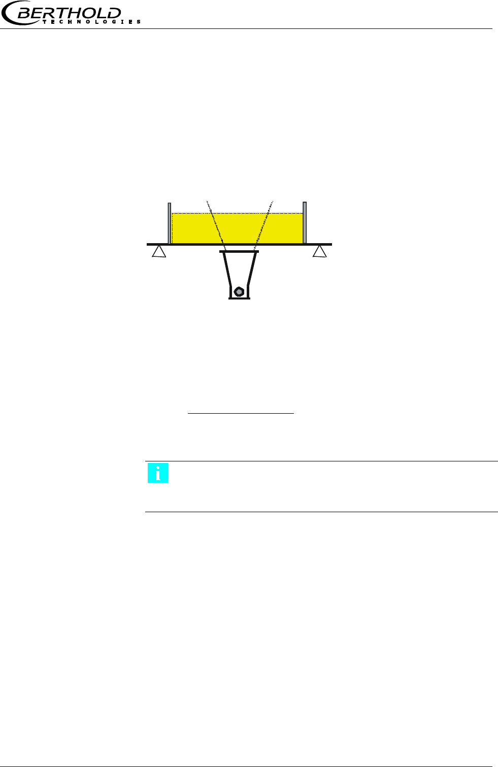
Chapter 7 Other Compensation Options
MircoPolar Moist LB 568 67
7.1.3 Weight/Throughput Compensation
If the material cross-section is rectangular (see Fig. 7-1), the mass
per unit area [g/cm²] is proportional to the weight per length
[kg/m]. Thus, the loading compensation becomes linear; it is
calculated as follows:
Load = Weight [kg] Eq. 7-3
The 0(4)...20 mA signal is supplied by an existing weighing
system.
If the weighing system supplies a throughput signal (T/h), either
the conveyor belt speed must be constant, or the belt speed must
be fed as 0(4)…20 mA signal into the evaluation unit via the
second current input. The compensation is then calculated
according to:
]s/m[ speed Belt
]h/T[ Throughput
Load
Eq. 7-4
IMPORTANT
The throughput signal must be fed in via current input 1 and the
speed signal via current input 2.
Figure 7-1:
Rectangular
material cross-section
with weighing system

Chapter 7 Other Compensation Options
68 MircoPolar Moist LB 568
7.1.4 Layer Thickness and Weight Compensation
The compensation of weight and layer height can be combined.
Prerequisite is a rectangular material cross-section, as described in
chapter 7.1.3. The compensation is then calculated according to:
Load = layer thickness [cm] x weight [kg] Eq. 7-5
The layer thickness and the weight supply a 0(4)...20 mA signal
each.
The compensation signal of the weighing station can be used as
throughput signal only if the speed is constant. Varying belt
speeds cannot be taken into consideration.
IMPORTANT
The weight signal must be fed in via current input 1 and the layer
thickness signal via current input 2.

Chapter 7 Other Compensation Options
MircoPolar Moist LB 568 69
7.2 Temperature Compensation
In general, temperature compensation (TC) is not required for bulk
material.
If the product temperature has a significant impact on the
microwave measuring signals phase or attenuation, a TC should be
connected. To this end, a temperature signal (0/4.20 mA or PT-
100) is connected to the evaluation unit and the TC is activated in
the evaluation unit.
The evaluation unit is designed such that the required TC’s can be
calculated automatically. The variation in temperature where TC is
required is dependent on the product and the water content.
The TC corrects the phase and attenuation before calculating the
measured value (calibration), in most applications according to the
following formulas (linear compensation, additive).
K
messkomp
Eq. 7-6
Dmesskomp KDD
Eq. 7-7
Where:
meas = measured phase
comp = compensated phase
Dmeas = measured attenuation
Dmeas = compensated attenuation
K = temperature coefficient of the phase
Katt = temperature coefficient of the attenuation
= measured temperature (Tmeas ) – reference temp. (TRef)
Depending on the selected function (additive, multiplicative,
quadratic, cubic), the required temperature coefficients appear on
the Calibration menu. Temperature coefficients that are not used
are set to zero.
If you select two-range calibration (split concentration), separate
TC’s have to be entered for both concentration ranges. The
coefficients are entered in the course of calibration.
TC can be carried out via Pt100 or via current input. This has to be
defined on the Calibration menu. The Pt100 temperature range is
between –50 and +200 °C.
How to work with the temperature compensation is described in
detail in the Software Manual.

Chapter 7 Other Compensation Options
70 MircoPolar Moist LB 568
7.3 Synchronization of the Current Input
Signals
The LB 568 offers the option to synchronize the current input
signals with the microwave information. The current input signals
are stored temporarily.
This function is helpful, for example, if the weighing system (z. B.
belt weigher) is located in a certain distance from the microwave
measuring path. By means of the synchronization, both
measurements can be correlated with each other, so that both
measurement information come from the same product.
If a weight/throughput signal for loading compensation will be
used and if the weighing system is more than 5 m away from the
microwave measuring path, then - depending on the belt speed -
the weight/throughput signal has to be synchronized with the
microwave information so that both signals measure the same
product.
The minimum distance is: 5 x v Eq. 7-8
Where:
v = belt speed [m/s]
The permissible maximum distance of both measuring devices
depends on the belt speed and is calculated as follows:
Belt speed [m/s]
Maximum distance [m]
< 1
50
> 1
100
Min. distance
Max. distance
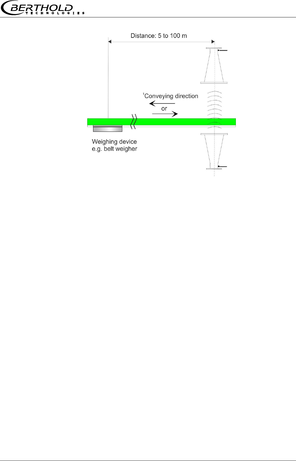
Chapter 7 Other Compensation Options
MircoPolar Moist LB 568 71
Figure 7-2:
Synchronized
belt weigher signal
1 The weighing system
can be set up before or
after the microwave
measuring path.
The belt speed should not exceed 5 m/s when the synchronization
is used.
Varying conveyor belt speed
A varying belt speed has to be taken into account for the
synchronization. The speed signal has to be fed into the evaluation
unit as 0/4…20 mA via current input 2.
Belt speed

Chapter 8 Radiation Protection Guidelines
72 MircoPolar Moist LB 568
Chapter 8. Radiation Protection
Guidelines
8.1 Basics and Directives
The radioactive isotopes used for mass per unit area
measurements emit gamma radiation. Gamma radiation consists
of high-energy electromagnetic radiation, i.e. it is a type of
radiation which resembles light, but has a much higher energy, so
that it can pass through matter having a higher density. This high-
energy radiation is hazardous to living beings (cell damage and
mutations). To keep this risk low, radioactive materials must be
handled carefully.
The radioactive sources used for mass per unit area measurements
are usually sealed sources, i.e. the actual radioactive substance is
surrounded by at least one, often several sealed layers made of
stainless steel, each of which is checked individually for leaks.
Another check ensures that no radioactive particles are deposited
on the surface of the capsule. The user will receive an official
certificate specifying these features of the radioactive source.
To avoid health hazards when working with radioactive substances,
limits for the maximum permissible radiation exposure of operating
personnel have been established on an international level. The
following information refers to the German Radiation Protection
Ordinance as of August 2001.
Appropriate measures in the design of the shieldings and the
arrangement of the measuring device at the measuring location
ensure that the radiation exposure of the personnel will remain
below the maximum permissible value of 1 mSv (100 mrem) per
year.
To ensure proper handling and compliance with statutory
requirements, the company must appoint a Radiation Protection
Officer who is responsible for all radiation protection issues
associated with the measuring equipment.
The Radiation Protection Officer shall monitor the use of the
radiometric measuring device and, if necessary, formalize the
safeguards and any special precautions applicable to a given
establishment in formal procedural instructions, which in special
cases may serve as a basis for radiation protection guidelines. This
may be necessary, for example, if a container can be accessed
and, therefore, it must be ensured that the active beam is shielded
first by the shielding. Radiation protection zones outside the
shielding - if they are accessible - must be marked and guarded.
These instructions should also include checks of the shutter device
of the shielding and measures for serious operational trouble -
such as fire or explosion.

Chapter 8 Radiation Protection Guidelines
MircoPolar Moist LB 568 73
Unusual incidents must immediately be reported to the Radiation
Safety Officer who will then investigate any damage on site and
immediately take suitable precautions if he detects defects that
may adversely affect the function or safety of the system.
The Radiation Protection Officer has to ensure also that the
provisions of the Radiation Protection Ordinance are complied with.
In particular, his duties include instructing the staff on the proper
handling of radioactive substances.
Radioactive sources that are no longer in use or have reached the
end of their service life must be returned to a public collection
point or to the supplier.
Basically, every company employee should strive, through prudent
behavior and by observing the radiation protection rules, to keep
the radiation exposure, even within the permissible limits, as low
as possible.
The sum of the radiation absorbed by the body is determined by
three variables, which can be derived from the basic radiation
protection rules:
Chapter 8 Radiation Protection Guidelines
74 MircoPolar Moist LB 568
Distance
This means the distance between radioactive source and human
body. The radiation intensity (dose rate) follows - just like light - an
inverse square law. This means that doubling the distance from the
source will reduce the dose rate to a quarter.
Conclusion:
Keep the maximum distance when carrying out any work in the
vicinity of equipment containing radioactive material. This is
especially true for persons who are not directly involved in this
work.
Time
The total time a person stays in the vicinity of a radiometric
measuring system and the body is exposed to radiation. The effect
is cumulative and is, therefore, greater the longer the exposure to
radiation.
Conclusion:
Required work in the vicinity of radiometric measuring devices has
to be carefully prepared and organized so that it can be done in the
shortest possible time. Providing the proper tools and resources is
particularly important.
Shielding
The shielding effect is provided by the shielding material
surrounding the source. Because the shielding effect is in an
exponential relationship to the product of thickness and density of
the shielding material, shielding materials with high specific weight
are required. Sufficiently large dimensions of the shieldings are
usually calculated by the supplier.
Conclusion:
Before installing or dismantling the shielding, make sure that the
radiation exit channel is closed. The source must not be removed
from the shielding and must not remain unshielded.

Chapter 8 Radiation Protection Guidelines
MircoPolar Moist LB 568 75
8.2 Emergency Instructions
In case of serious operational trouble, such as fire or explosion,
which may affect the radiometric measuring system, it cannot be
ruled out that the function of the shielding lock, the shielding
effect or the stability of the source capsule have been
compromised. In this case, it is possible that persons in the vicinity
of the shielding have been exposed to higher levels of radiation.
If you suspect such a severe malfunction, the Radiation Safety
Officer has to be notified immediately. He will then investigate the
situation immediately and take all necessary provisions to prevent
further damage and to avoid any unnecessary radiation exposure
of operating personnel.
The Radiation Safety Officer has to make sure that the measuring
system is no longer in operation and then take appropriate steps.
He may have to inform the authorities or contact the manufacturer
or supplier of the measuring system, so that any further action be
taken under expert supervision.
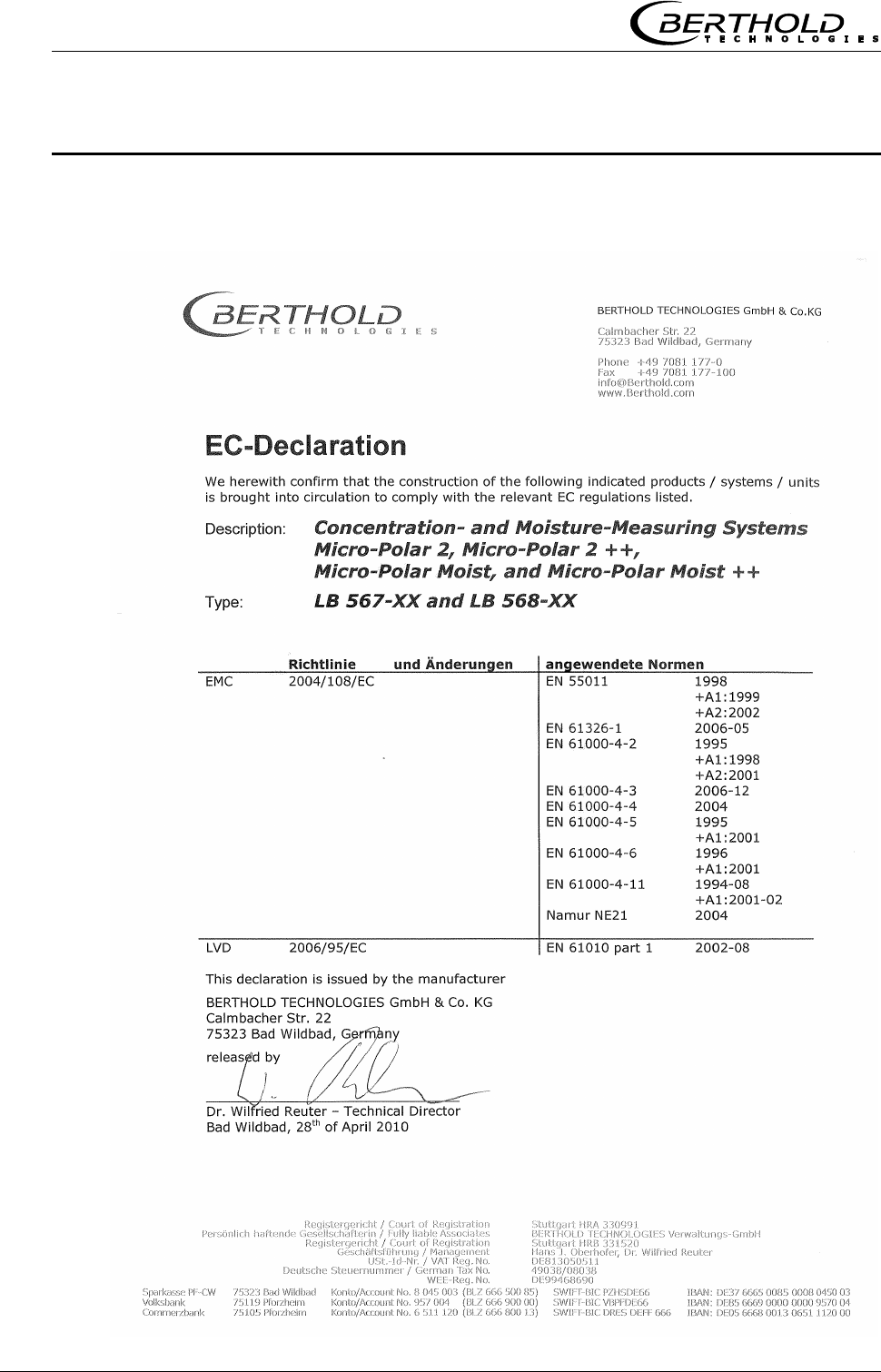
Chapter 9 Certificates
MircoPolar Moist LB 568
Chapter 9. Certificates
9.1 EC Declaration of Conformity
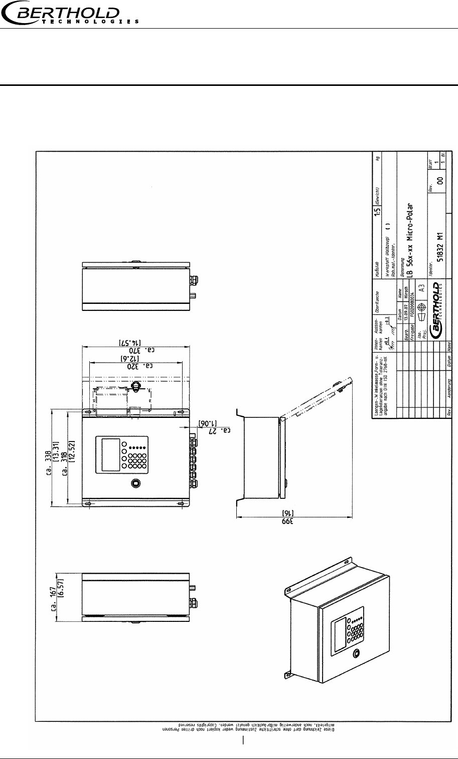
Chapter 10 Technical Drawings
MircoPolar Moist LB 568 77
Chapter 10. Technical Drawings
10.1 Dimensional Drawing Evaluation Unit Case
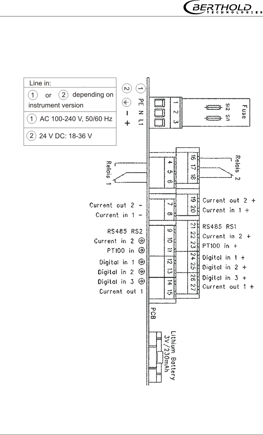
Chapter 10 Technical Drawings
78 MircoPolar Moist LB 568
10.2 Electrical Wiring Diagram
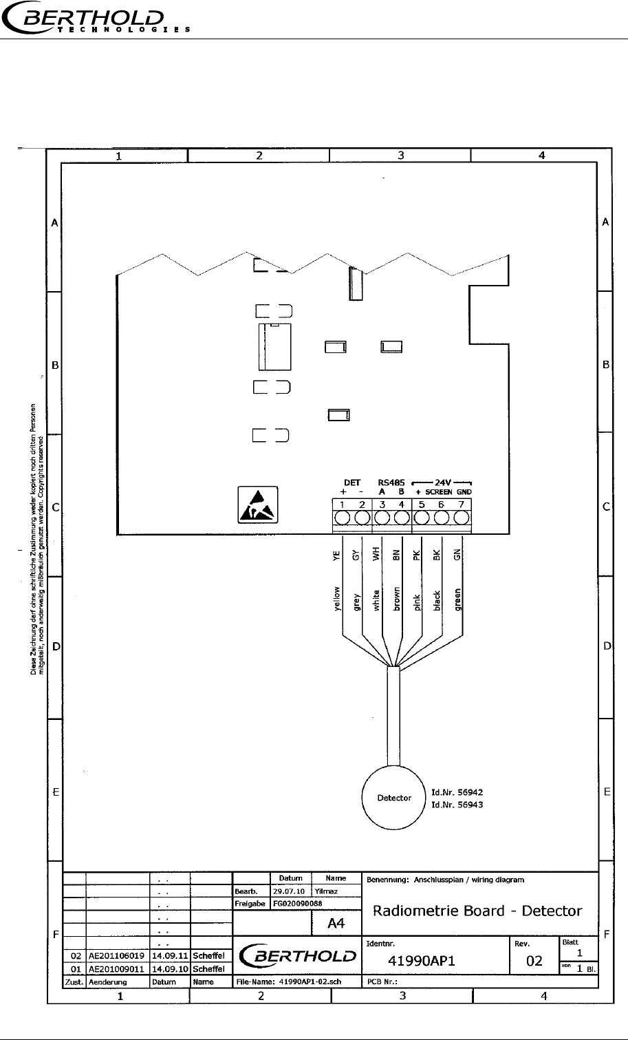
Chapter 10 Technical Drawings
MircoPolar Moist LB 568 79
10.3 Electrical Wiring Diagram Scintillation Counter
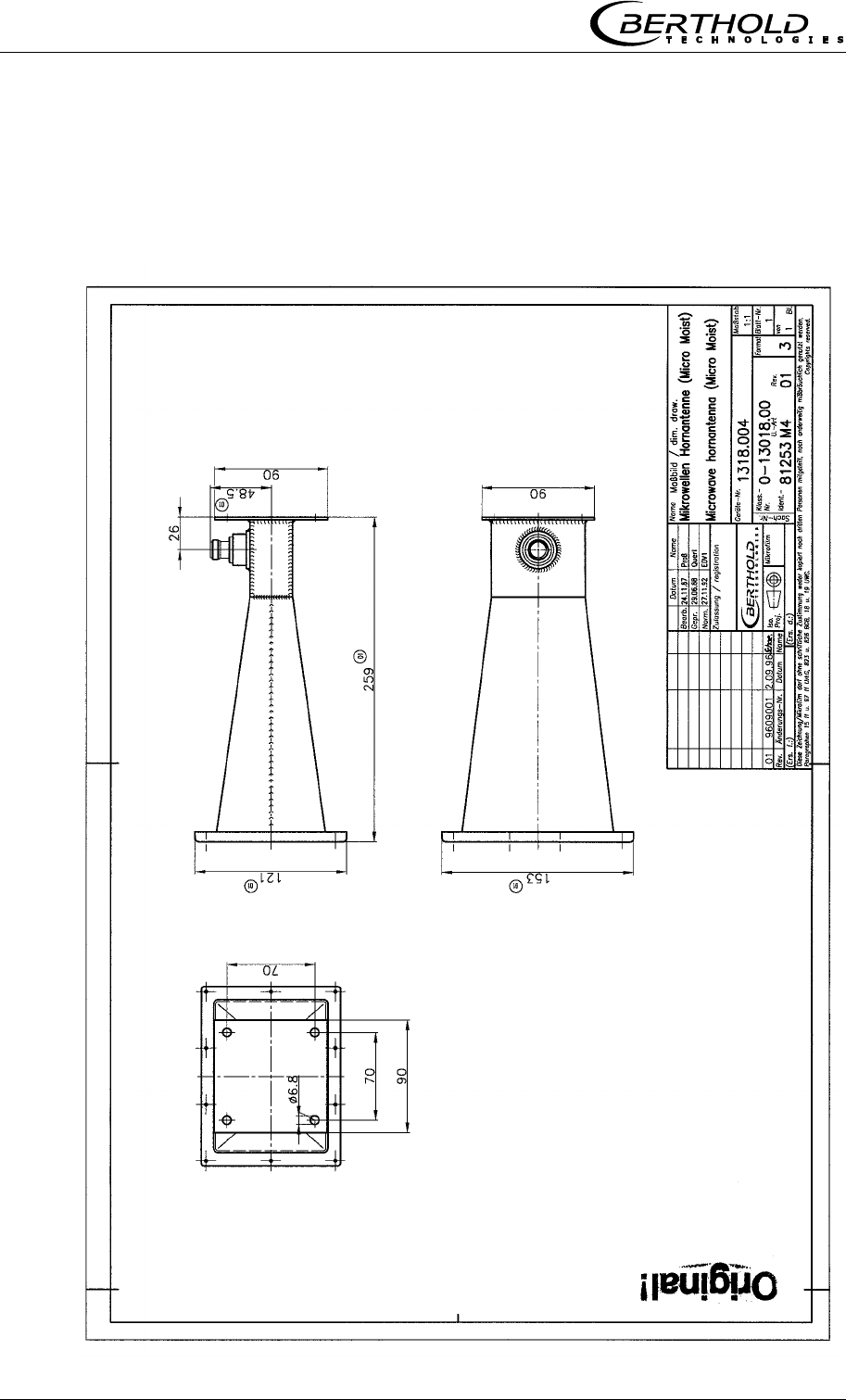
Chapter 10 Technical Drawings
80 MircoPolar Moist LB 568
10.4 Dimensional Drawings Horn and Spiral Antennas
10.4.1 Horn Antenna and Horn Antenna Brackets
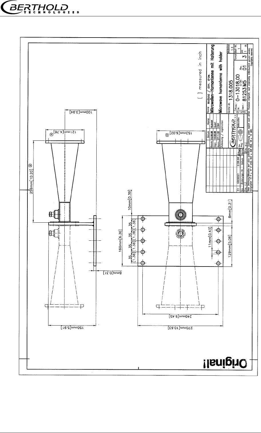
Chapter 10 Technical Drawings
MircoPolar Moist LB 568 81
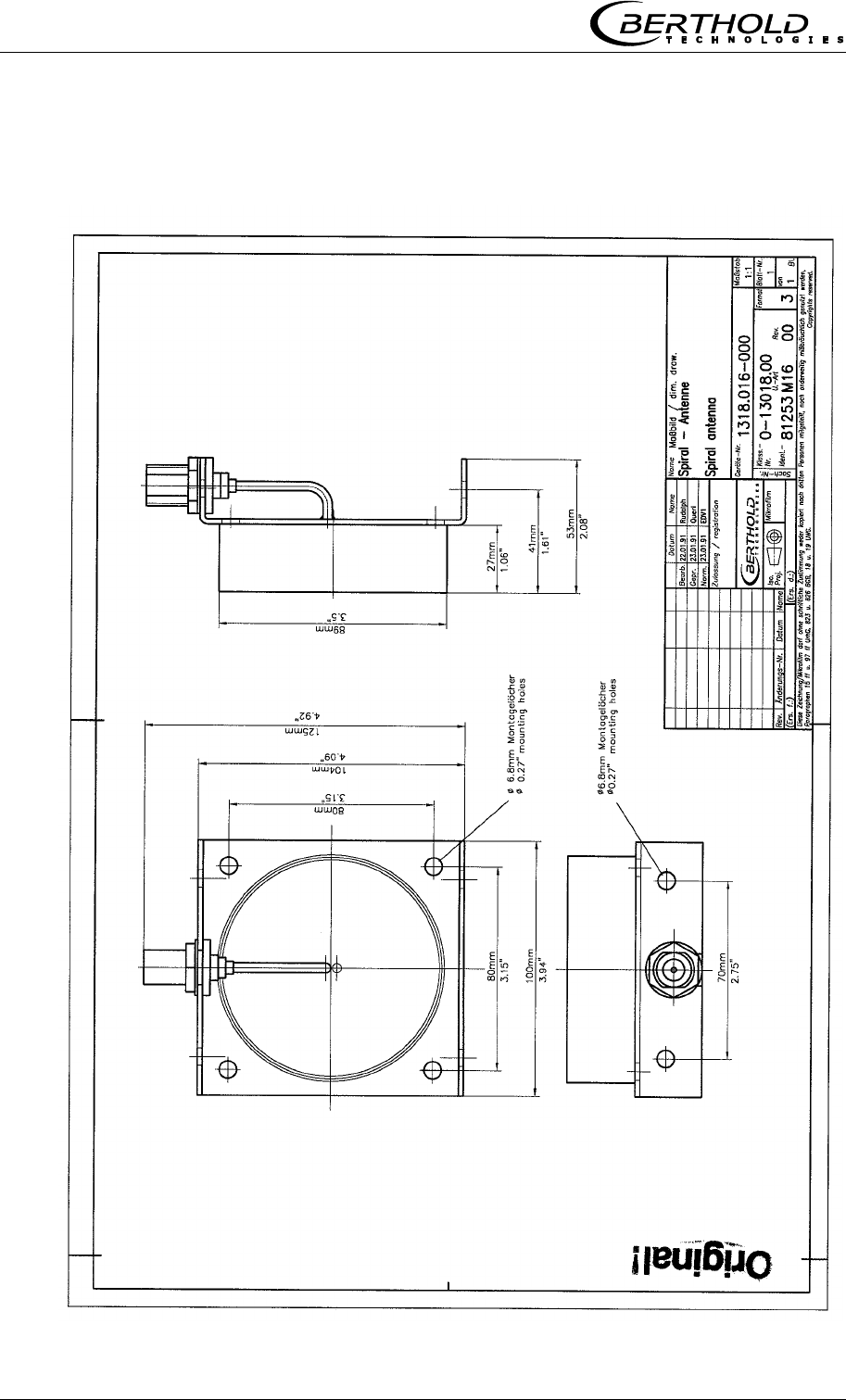
Chapter 10 Technical Drawings
82 MircoPolar Moist LB 568
10.4.2 Spiral Antennas
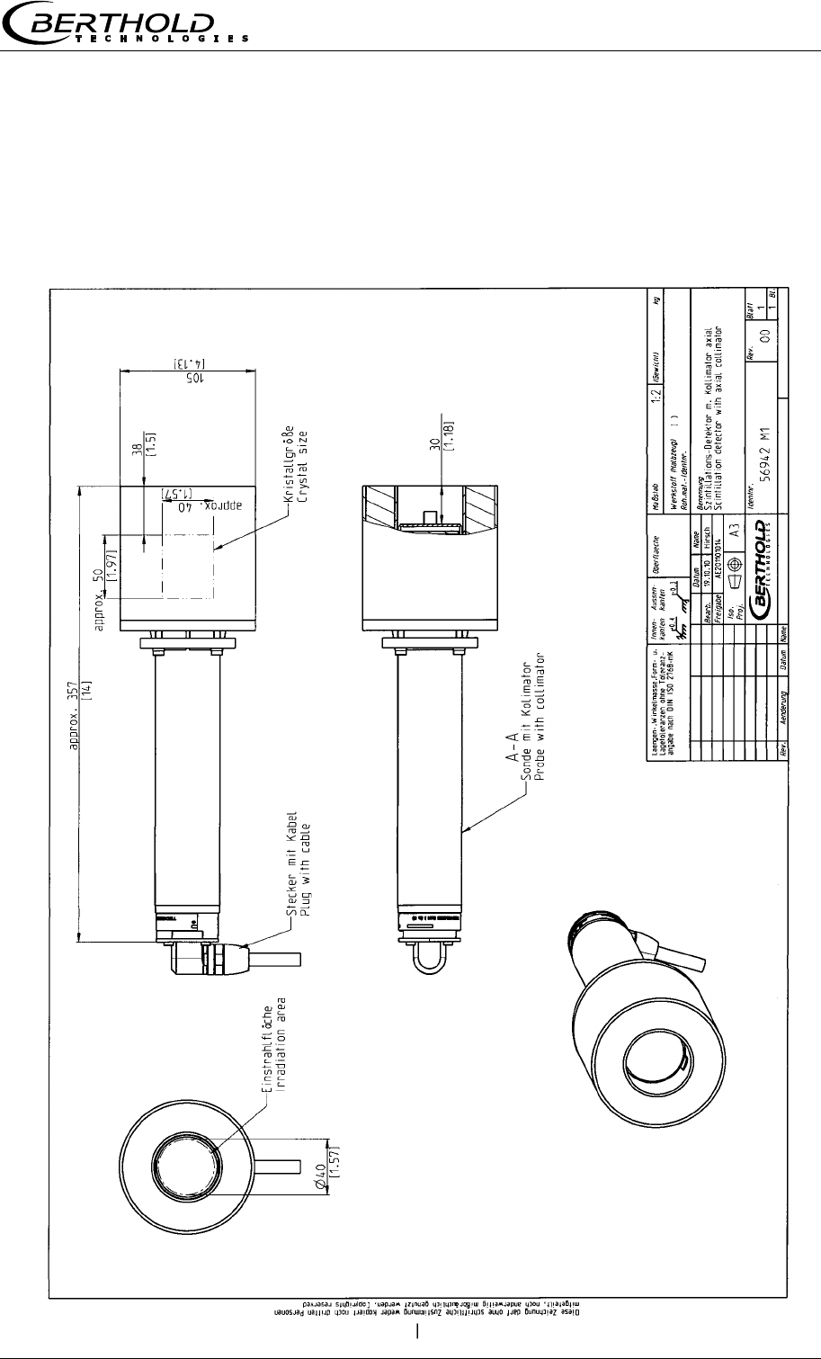
Chapter 10 Technical Drawings
MircoPolar Moist LB 568 83
10.5 Dimensional Drawings Radiometric Measuring Path
10.5.1 Scintillation Counter with Axial Collimator
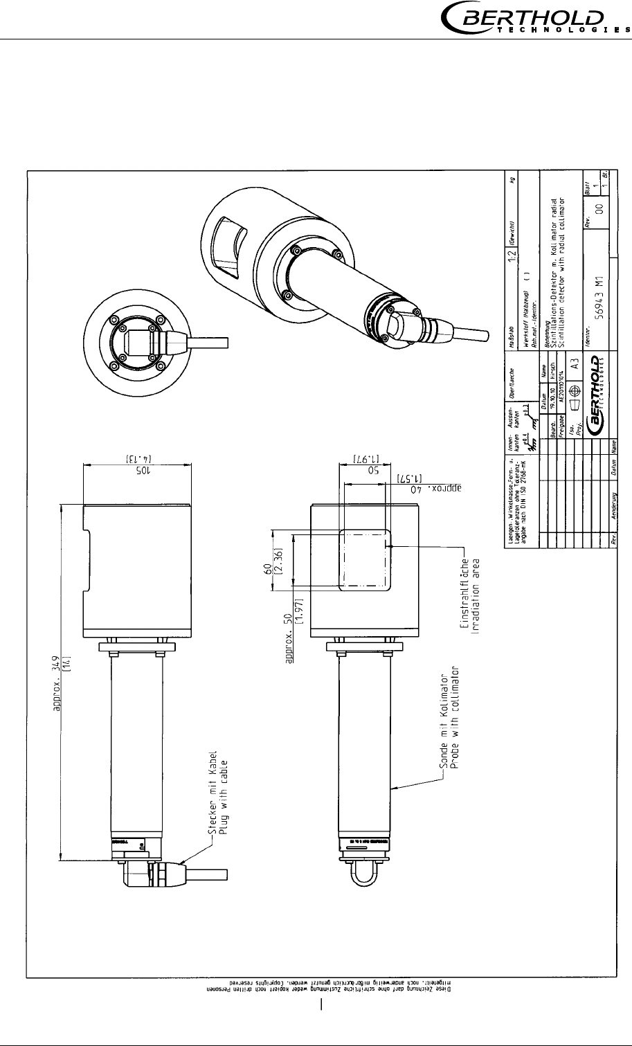
Chapter 10 Technical Drawings
84 MircoPolar Moist LB 568
10.5.2 Scintillation Counter with Radial Collimator
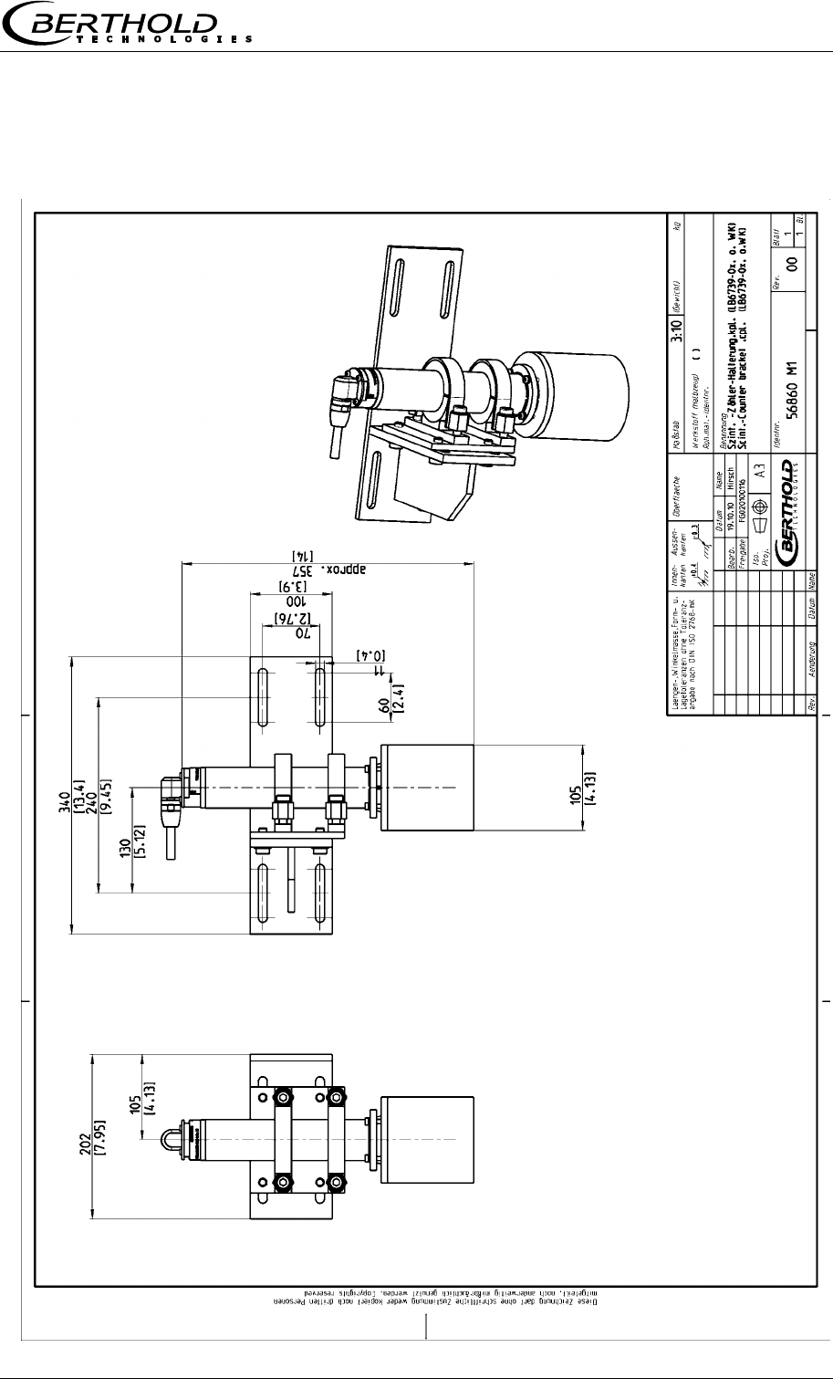
Chapter 10 Technical Drawings
MircoPolar Moist LB 568 85
10.5.3 Scintillation Counter with Bracket
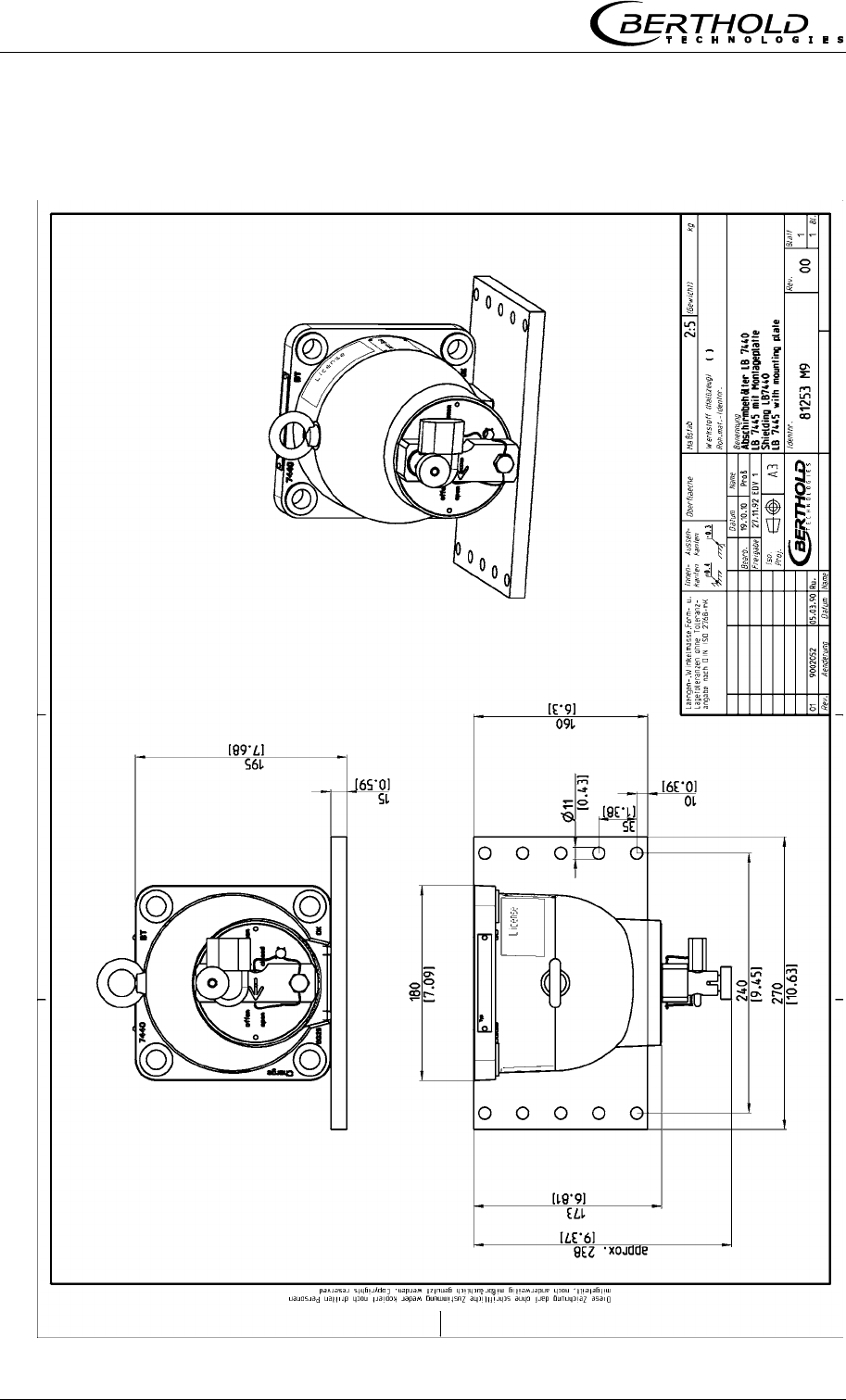
Chapter 10 Technical Drawings
86 MircoPolar Moist LB 568
10.5.4 Shielding Container LB 7440/5 with Mounting Plate
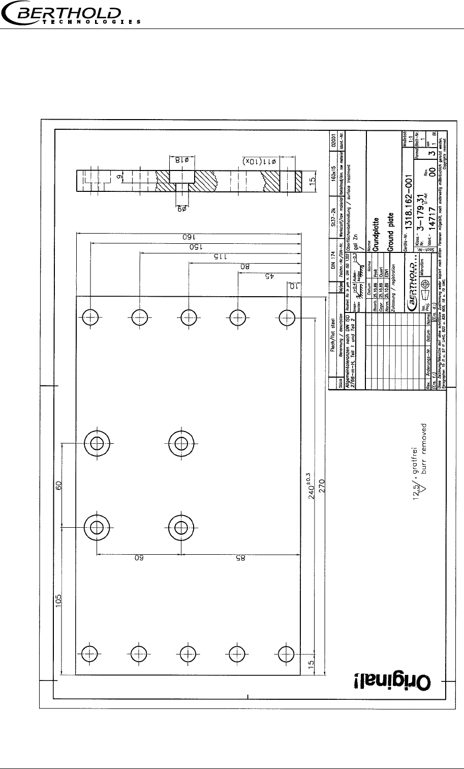
Chapter 10 Technical Drawings
MircoPolar Moist LB 568 87
10.5.5 Mounting Plate for Shielding Container
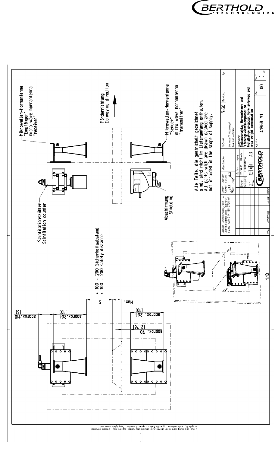
Chapter 10 Technical Drawings
88 MircoPolar Moist LB 568
10.6 Installation Proposal at the Conveyor Belt
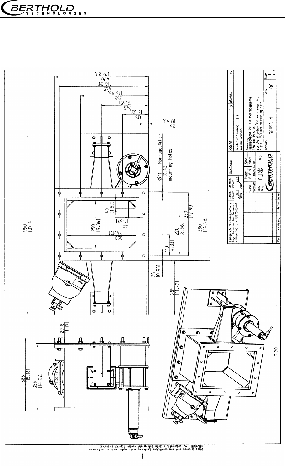
Chapter 10 Technical Drawings
MircoPolar Moist LB 568 89
10.7 Installation Proposal at the Measuring Chute

Index
90 MircoPolar Moist LB 568
Index
A
Accuracy .............................................................................. 56
Antenna distance ................................................................. 24
Assembly conditions ............................................................ 24
B
Battery ................................................................................. 54
C
Calculation of measured values ........................................... 15
Chute measurement configuration...................................... 32
Compensation ...................................................................... 16
Components ........................................................................ 20
Conductive materials ........................................................... 16
Connection scintillation counter .......................................... 52
Connector strip .................................................................... 50
Conveyor measurement configuration ................................ 31
D
Data format RS232............................................................... 64
Data transfer rate ................................................................ 52
Digital outputs ..................................................................... 53
Dimensional drawing EVU case ........................................... 77
E
Evaluation unit ............................................................... 13, 22
F
Factory setting ..................................................................... 13
Format RS232 ...................................................................... 64
Fuses .................................................................................... 55
G
Gas inclusions ...................................................................... 12
H
HF cable ............................................................................... 30
Horn antennas ..................................................................... 24
I
Instrument cleaning ............................................................. 54
L
Law of absorption ............................................................... 19
LED’s .............................................................................. 23, 53
Limitations .......................................................................... 16
Loading compensation ........................................................ 17
M
Mains connection ................................................................ 49
Mains fuses ......................................................................... 55
Mass per unit area ........................................................ 18, 19
Measuring chute ................................................................. 29
Measuring conditions .................................................... 34, 46
Minimum load ..................................................................... 35
O
Optional loading compensation .......................................... 66
P
Parts subject to wear .......................................................... 54
Polarization ..................................................................... 24
Principle of measurement ................................................... 14
R
Radiometric measuring path ............................................... 26
Reference temperature ....................................................... 69
Relay .................................................................................... 53
RS232 interface ................................................................... 52
RS485 interface ................................................................... 51
S
Safety Summary .................................................................... 7
Salt content ......................................................................... 12
Service instructions ............................................................. 54
Shielding .............................................................................. 27
Spiral antennas .................................................................... 24
Steel-wire reinforced conveyor belt.............................. 38, 44
Symbols ................................................................................. 7
Synchronization ................................................................... 70
T
Technical data ..................................................................... 56
Technical data HF-cable ...................................................... 63
Technical drawings .............................................................. 77
Temperature compensation ......................................... 16, 69

Index
MircoPolar Moist LB 568 91
Terminal blocks ................................................................... 23
Torque of HF connector ...................................................... 45
Transmission power ............................................................ 56
Transport ............................................................................. 33
W
Warning ................................................................................. 7
Wiring diagram .................................................................... 78
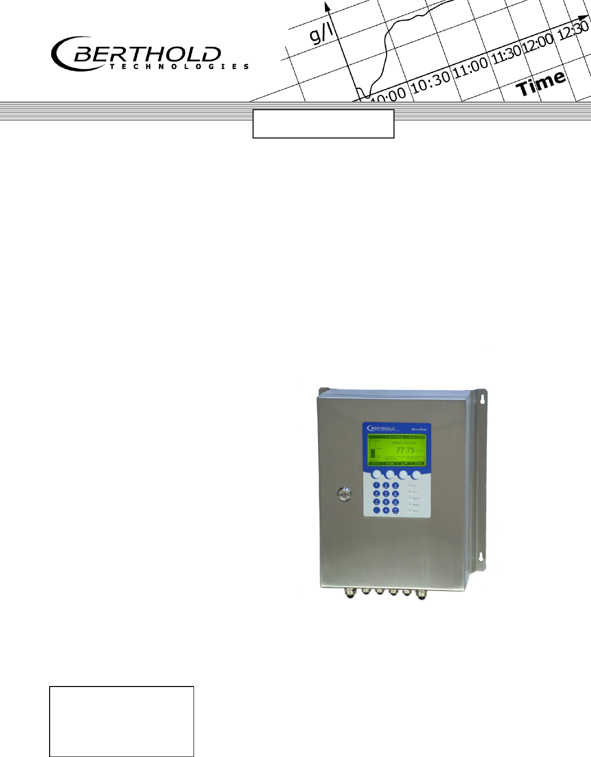
detect and identify
Process Control
ID No. 41990BA2
Rev. No.: 02 15.06.2015
Software Version ≥ 1.0
User's Guide
- Software Manual -
Concentration / Moisture
Measuring System
MicroPolar Moist
LB 568

MicroPolar Moist LB 568
The units supplied should not be repaired by anyone other than Berthold
Technologies Service engineers or technicians by Berthold Technologies.
In case of operation trouble, please address to our central service department
(address see below).
The complete user’s guide consists of two manuals, the hardware description and the software
description.
The hardware manual comprises the
safety summary
component description
assembly instructions
electrical installation description
technical data
certificates
dimensional drawings
The software manual comprises the description of the
operation
software functions
calibration
error messages
The present manual is the software description.
Subject to changes without prior notice.
BERTHOLD TECHNOLOGIES GmbH & Co. KG
Calmbacher Str. 22 75323 Bad Wildbad, Germany
Phone +49 7081 177 0 Phone +49 7081 177 111
Fax +49 7081 177 100 Fax +49 7081 177 339
industry@Berthold.com Service@Berthold.com
www.Berthold.com

Table of Contents
4 MicroPolar Moist LB 568
Table of Contents
Page
CHAPTER 1. SAFETY SUMMARY ................................................................................................................................... 6
CHAPTER 2. GENERAL INFORMATION.......................................................................................................................... 7
CHAPTER 3. SOFTWARE FUNCTIONS............................................................................................................................ 8
3.1 INFORMATION ON THE MENU STRUCTURE.................................................................................................................... 8
3.2 MENU STRUCTURE .................................................................................................................................................. 9
3.2.1 Start Menu ................................................................................................................................................ 11
3.2.2 Diagnostic ................................................................................................................................................. 11
3.2.3 Setup ......................................................................................................................................................... 13
3.2.4 Access Level .............................................................................................................................................. 14
3.2.5 Language .................................................................................................................................................. 14
3.2.6 Configuration ............................................................................................................................................ 15
3.2.7 General Data ............................................................................................................................................ 17
3.2.8 Measurement ........................................................................................................................................... 17
3.2.9 Plausibility ................................................................................................................................................ 17
3.2.10 Phase Measure ......................................................................................................................................... 18
3.2.11 Synchronization ........................................................................................................................................ 20
3.2.12 Calibration ................................................................................................................................................ 21
3.2.13 System Adjust ........................................................................................................................................... 21
3.2.14 Calibrate Concentration............................................................................................................................ 22
3.2.15 Sample Table ............................................................................................................................................ 23
3.2.16 Sample Data (expanded) .......................................................................................................................... 24
3.2.17 Advanced .................................................................................................................................................. 24
3.2.18 Calibration ................................................................................................................................................ 25
3.2.19 Temperature Compensation ..................................................................................................................... 26
3.2.20 Loading Compensation ............................................................................................................................. 27
3.2.21 Inputs / Outputs ........................................................................................................................................ 29
3.2.22 Current Output ......................................................................................................................................... 29
3.2.23 Current Out 1 ............................................................................................................................................ 29
3.2.24 Current Out 2 ............................................................................................................................................ 30
3.2.25 Current Input ............................................................................................................................................ 31
3.2.26 Current In 1 ............................................................................................................................................... 31
3.2.27 Current In 2 ............................................................................................................................................... 31
3.2.28 PT100 ........................................................................................................................................................ 32
3.2.29 Digital Output ........................................................................................................................................... 33
3.2.30 Digital Input .............................................................................................................................................. 33
3.2.31 Service....................................................................................................................................................... 35
3.3 MENU STRUCTURE RADIOMETRIC DETECTOR .............................................................................................................. 37
3.3.1 Configuration Radiometric Detector......................................................................................................... 37
3.3.2 Service Radiometric Detector ................................................................................................................... 39
3.4 LIVE DISPLAY ........................................................................................................................................................ 41

Table of Contents
MicroPolar Moist LB 568 5
CHAPTER 4. CONFIGURATION .................................................................................................................................... 42
4.1 CONFIGURATION SETUP ........................................................................................................................................... 42
4.1.1 General Data ............................................................................................................................................. 42
4.1.2 Measurement ............................................................................................................................................ 43
4.1.3 Plausibility ................................................................................................................................................. 43
4.1.4 Microwave/Cable ...................................................................................................................................... 44
4.1.5 Configuration Radiometry ......................................................................................................................... 45
4.1.6 Marker ....................................................................................................................................................... 45
4.1.7 Units .......................................................................................................................................................... 46
4.2 START CALIBRATION COEFFICIENTS ............................................................................................................................ 47
4.3 CONFIGURATION PLAUSIBILITY .................................................................................................................................. 48
CHAPTER 5. CALIBRATION ......................................................................................................................................... 49
5.1 SCINTILLATION COUNTER CALIBRATION ...................................................................................................................... 49
5.2 SYSTEM CALIBRATION ............................................................................................................................................. 50
5.2.1 Verifying the Reference Values .................................................................................................................. 52
5.2.2 Tare Measurement .................................................................................................................................... 53
5.3 SAMPLING ............................................................................................................................................................ 55
5.3.1 Entering the Lab Values ............................................................................................................................. 58
5.4 CALIBRATION ......................................................................................................................................................... 59
CHAPTER 6. CALIBRATION AND OPTIONS .................................................................................................................. 60
6.1 CONFIGURATION PHI/ATT RATIO PLAUSIBILITY ............................................................................................................ 60
6.1.1 Phi/Att Ratio .............................................................................................................................................. 60
6.1.2 Process Recording ..................................................................................................................................... 61
6.2 ADJUSTING THE CALIBRATION ................................................................................................................................... 63
6.3 OUTPUT OF THE START-UP LOG ................................................................................................................................ 65
6.4 CALIBRATION ......................................................................................................................................................... 66
6.4.1 Calibration with One Concentration .......................................................................................................... 66
6.4.2 Calibration with Temperature Compensation ........................................................................................... 69
6.4.3 Calibration with Load Compensation ........................................................................................................ 71
6.4.4 Calibration with Two Concentrations ........................................................................................................ 73
6.4.5 Calibration with Split Value ....................................................................................................................... 77
6.4.6 Extended Calibration Mode ....................................................................................................................... 80
6.5 TYPICAL CALIBRATION COEFFICIENTS/START VALUES ..................................................................................................... 82
CHAPTER 7. PASSWORD ............................................................................................................................................ 83
7.1 PASSWORD FORGOTTEN .......................................................................................................................................... 84
CHAPTER 8. ERROR LISTS AND DEVICE STATES .......................................................................................................... 85
8.1 HARDWARE ERROR AND WARNING MESSAGES ............................................................................................................ 85
8.2 INPUT ERROR ........................................................................................................................................................ 86
8.3 MEASUREMENT ERROR AND ERROR MESSAGES ........................................................................................................... 86
8.4 DEVICE STATES ...................................................................................................................................................... 88
CHAPTER 9. START-UP LOG ........................................................................................................................................ 89
9.1 EXAMPLE START-UP LOG ......................................................................................................................................... 93

Chapter 1 Safety Summary
6 MicroPolar Moist LB 568
Chapter 1. Safety Summary
Please observe all safety instructions in the hardware part,
especially those in chapter 1 Safety Summary.
Parameter settings
Never change the installation and the parameter settings without
a full knowledge of these operating instructions, as well as a full
knowledge of the behavior of the connected controller and the
possible influence on the operating process to be controlled.
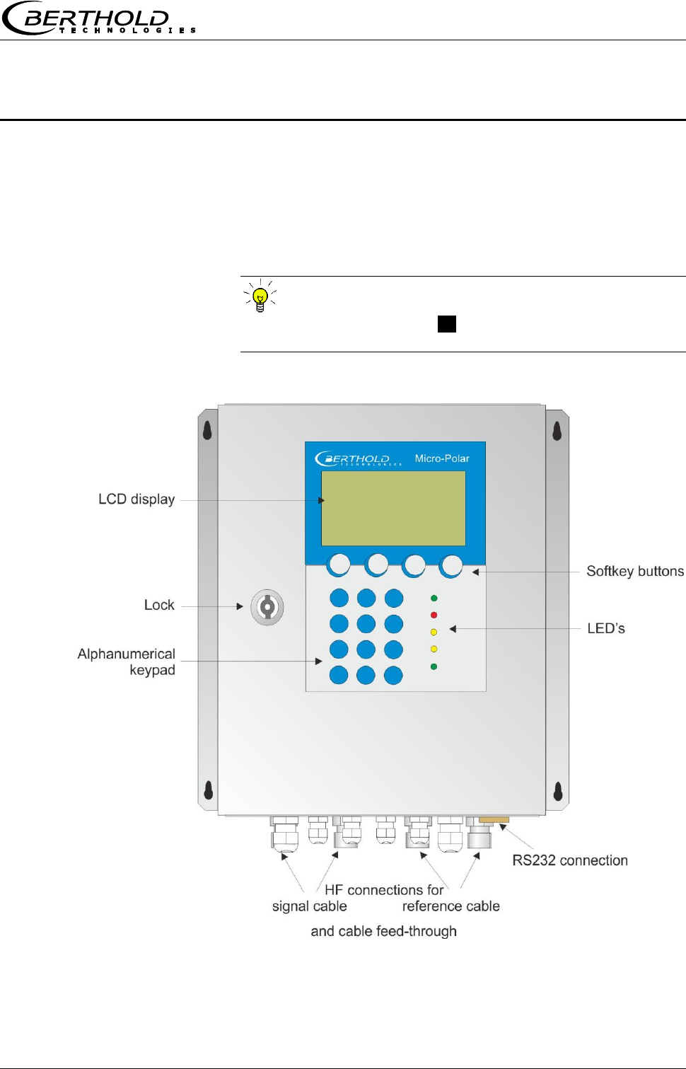
Chapter 2 General Information
MicroPolar Moist LB 568 7
Chapter 2. General Information
Communication with the LB 568 takes place via 4 softkey
buttons. The function of the individual buttons changes
relative to the position in the menu. Values and texts are
entered via an alphanumeric keyboard. The instrument
status is indicated by 5 LED’s.
TIP
Click on the help button .?. in the display footer to view
useful information.

Chapter 3 Software Functions
8 MicroPolar Moist LB 568
Chapter 3. Software Functions
3.1 Information on the Menu Structure
The menu structure on the following pages provides an
overview of all functions of the LB 568. Using the page
numbers indicated you can look up the function of the
depicted window.
Depending on the access level, some menu items are hidden.
You have to enter an editable password to change from the
Read only level to Basic or Profi. The Service level is
locked; it is foreseen only for equipment manufacturing.
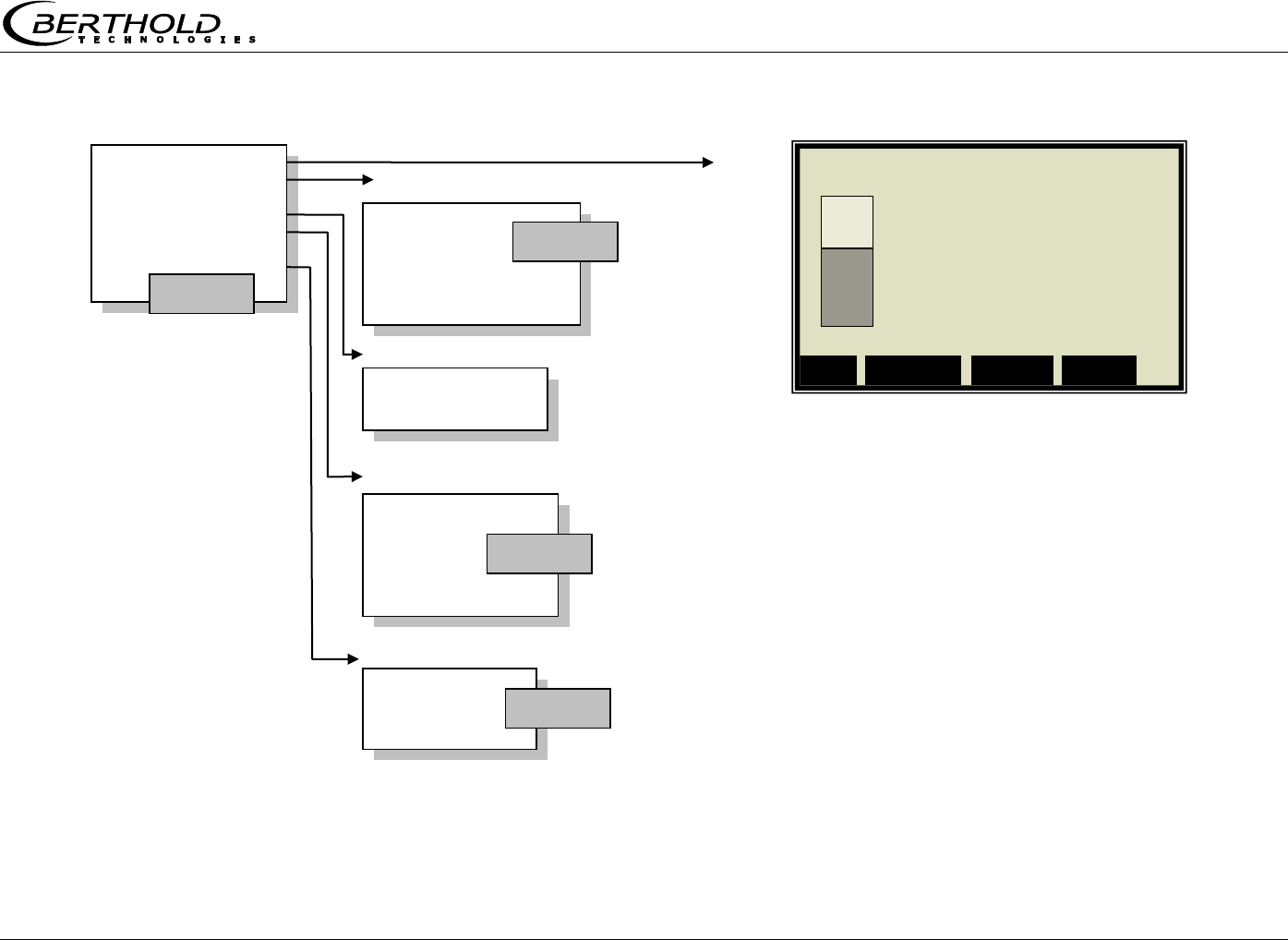
Chapter 3 Software Functions
MicroPolar Moist LB 568 9
3.2 Menu Structure
Live Display
Diagnostic
Setup
Access level
Language
Datalog
Error log
Info
Print Setup
Diagnostic
English
German
French
Language
Read only
Basic
Profi
Service
Access Level
See next page
Setup
Page 11
Page 11
Page 14
Page 14
1 | - | Live Display | 07.05 – 13:25
Concentration av.
65.50 %
Conc. av. Conc. act. 64.35%
ESC SAMPLE ..▼▲.. ZOOM
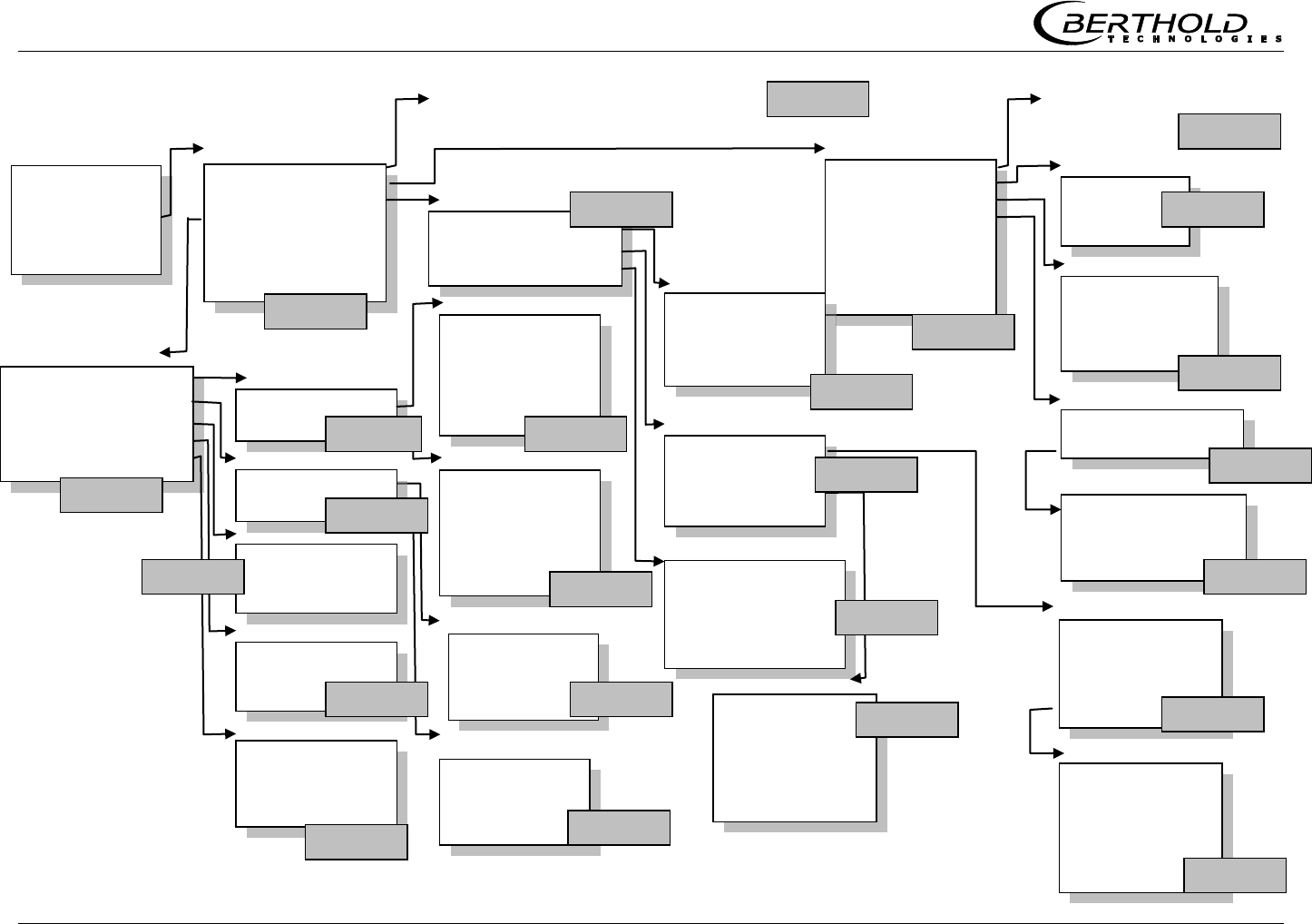
Chapter 3 Software Functions
10 MicroPolar Moist LB 568
Live Display
Diagnostic
Setup
Access level
Language
General data
Measurement
Plausibility
Microwave
Radiometry
Marker
Units
Synchronization
Configuration
Configuration
Calibration
Input / Output
Service
Product
Change password
Setup
Measurement
Meas. mode
Start mode
Averaging
Reset averaging
Plausibility
Process limits
Phase measure
Phi offset max
Sigma max.
Phi/Att ratio
Auto set
General data
Date
Time
Tag
Calibration
System adjust
Calibrate Conc
Advanced
System adjust
Adjust
Reference values
Chart Phi
Chart Attenuation
Calibrate Conc
Sampling
Calibration
Tuning
View
Advanced
Tare values
Num cal. sweeps
Process type
Split value
Extended cal. mode
Inputs / Outputs
Current output
Current input
PT100
Digital output
Digital input
Current out 1
’’ 2
2
Current Out 1
Assignment
0/4 mA
20 mA
Test/Adjust
Error current
Current Out 2
Assignment
0/4 mA
20 mA
Range
Test/Adjust
Error current
Current In 2
Enabled
Adjust
Live current
Cal. order
Cal. base
Coefficients
Temp. comp.
Loading comp.
Start Calibration
Calibration
Current In 1
Enabled
Adjust
Live current
Page 13
Page 15
Page 17
Page 17
Page 17
Page 18
Page 21
Page 21
Page 22
Page 24
Page 25
Page 29
Page 30
Page 29
Page 31
Page 31
Current output
Current input
Current in 1
’’ 2
Pt100
Enabled
Adjust PT100
PT100 live
Digital Output
Relay 1
Relay 2
Test
Digital input
Status
DI 1 function
DI 2 function
DI 3 function
Page 29
Page 31
Page 32
Page 33
2422424
Page 33
Next sample
Active
Measured value
Lab Value
Extended
Current in 1
Current In 2
Pt 100
PHI (m)
Attenuation
Mpua
Sampling
Advanced
Page 23
Page 24
Radiometric detector
Page 37
Under Service Radiometric detector
Page 39
Chapter 3 Software Functions
MicroPolar Moist LB 568 11
3.2.1 Start Menu
LIVE DISPLAY:
Shows the live display.
DIAGNOSTIC:
This menu item contains the submenu items data logger,
error log, instrument information and start-up log output.
SETUP:
All necessary inputs for operation of the measuring system
can be entered here.
ACCESS LEVEL:
Select the access level.
Areas protected by passwords can be cleared.
LANGUAGE:
Select the dialog language.
3.2.2 Diagnostic
Data log:
The data log records the data corresponding with the
format of the serial data output RS232 (see Hardware
Manual, chapter 6.6).
All measured data of a measurement (Sweep) are
averaged over the averaging time (see below) and stored.
This time is dependent on the selected log time. The
contents of the data log can be displayed on the live
display, see chapter 3.4 Trend Display. It can also be
output as a text file via RS232, and via the memory stick
(optional accessory).
Log type Disable
Single
Continuous
Stop at error
Log time Logging period
15 minutes to 3 days
Restart log Clears the data log and starts with the
above setting
Averaging time Obtained from log time
Print setup Printout of table, output via
RS232, format see Hardware Manual,
chapter 6.1 Technical Data Evaluation
Unit
1 | - | LB 568 | 07.05 - 13:25
Live Display
Diagnostic
Setup
Access level
Language
RUN ▲ ▼ ►
1 | - | LB 568 | 07.05 – 13:25
Live Display
Diagnostic
Setup
Access level
Language
RUN ▲ ▼ ►
1 | - | LB 568 | 07.05 – 13:25
Live Display
Diagnostic
Setup
Access level
Language
RUN ▲ ▼ ►
1 | - | LB 568 | 07.05 – 13:25
Live Display
Diagnostic
Setup
Access level
Language
RUN ▲ ▼ ►
1 | - | LB 568 | 07.05 – 13:25
Live Display
Diagnostic
Setup
Access level
Language
RUN ▲ ▼ ►
1 | - | LB 568 | 07.05 – 13:25
LLive Display
Diagnostic
Setup
Access level
Language
RUN ▲ ▼ ►
1 | - | LB 568 | 07.05 – 13:25
Live Display
Diagnostic
Setup
Access level
Language
RUN ▲ ▼ ►
1 | - | LB 568 | 07.05 – 13:25
Live Display
1 | - | Diagnostic | 07.05 – 13:25
Datalog
Error log
Info
Print setup
⌂◄ ▲ ▼ ►

Chapter 3 Software Functions
12 MicroPolar Moist LB 568
Change data log settings:
If you change the log type from "any" to "single", the data
log will be cleared and you start again with the current
setting.
If you change all other log types and log times, the data
log will not be cleared and you continue with the new
settings.
Behavior with stopped measurement:
If the measurement will be stopped during the data log for
some time, then the measurement pause will be
interpreted as log time in the log type "single". In all other
log types, the measurement pause will be added to the log
time.
Error log:
Shows the logged error. The last 20 error messages will
be stored with date and time.
Info:
Tag :...
Device type : LB 568
Supplier : Berthold Technologies
Manufacturer : Berthold Technologies
Device no. : ...
Production no. : ...-...
Software ver. : V...
SW rev. date : ...
Print setup:
Output of the start-up log via RS232.
Format, contents and example see chapter 9. Start-up
Log.

Chapter 3 Software Functions
MicroPolar Moist LB 568 13
3.2.3 Setup
Configuration:
Setup of
General data
Measurement-specific data
Plausibility data
Microwave data
Radiometry data
Marker
Units
Synchronization
Calibration:
System adjust
Concentration calibration
Advanced
Input/Output:
Current outputs
Current inputs
PT100
Digital outputs
Digital inputs
Service:
In the Profi mode the SERVICE menu is displayed and can
be edited. The following settings are possible:
Factory settings
General reset
Memory stick (operation of the memory sticks,
optional accessory)
Data printout (via RS232, data contents can be
selected)
Product:
Product selection (1 – 4); if you select another product,
the product-specific data will be loaded: outputs, inputs
and calibration.
When you select the products 2 to 4 for the first time, all
settings and contents (e.g. system calibration, sampling
table, data log and calibration) of the current product will
be copied to the new product.
Change password:
The password for the access levels Basic / Profi can be
changed here.
For more information see chapter 7 Password.
1 | - | Setup | 07.05 – 13:25
Configuration
Calibration
Input / Output
Service
Product
Change password
⌂◄ ▲ ▼ ►
Chapter 3 Software Functions
14 MicroPolar Moist LB 568
3.2.4 Access Level
Read only:
Only the live display and the main menu can be
selected.
This mode can be selected on all levels without
password.
Basic:
No password required on higher levels. Password has
to be entered for Read only.
Password can be changed.
On the basic level, some menu items are hidden, for
example, the calibration.
Profi:
As described above. Should be used only if you are
sufficiently familiar with the measuring system.
Changing from Profi to Basic or vice versa is possible
without password.
Service:
This level is reserved for the service personnel.
3.2.5 Language
Language:
Select the dialog language
1 | - | Access Level | 07.05 – 13:25
Read only
Basic
Profi
Service
ESC ▲▼ ►
1 | - | LB 568 | 07.05 – 13:25
LANGUAGE
English
German
French
ESC ▲▼ .√.

Chapter 3 Software Functions
MicroPolar Moist LB 568 15
3.2.6 Configuration
General Data:
Enter date, time and tag
Measurement:
Measurement mode (batch/continuous)
Start mode (keyboard/external)
Averaging (number of measured values used for
averaging)
Reset average value (yes/no)
Plausibility:
The process limits define the permissible range within
which the actual concentration must lie.
The phase measurement is subject to a plausibility
analysis, which can be set here.
For more information please see chapter 3.2.9 Plausibility
Microwave:
Cable: Enter the cable lengths for the signal and
reference cable. For example, for 1.5 and 2.5 m
antenna cable and 4 m reference cable, you have to
enter 4 m for both lengths.
Radiometry:
Here, the radiometric detector is configured. Description
see chapter 3.3.1 Configuration Radiometric Detector.
Marker:
Enter a value and a name (up to 5 characters) for the
marker here. The presentation takes place in the live
display and refers to the bar chart. To disable the marker,
select a marker value outside the chart limits or the
current output limits.
1 | - | Configuration | 07.05 – 13:25
General Data
Measurement
Plausibility
Microwave
Radiometry
Marker
Units
Synchronization
⌂◄ ▲ ▼ ►

Chapter 3 Software Functions
16 MicroPolar Moist LB 568
Units:
Depending on the configuration, different units can be
selected for concentrations, current inputs and
temperature.
For the concentration (1 and 2) you can select:
none, specific, %, %DS
For current input 1 you can select:
none, specific, °C, °F, g/cm3, Kg, t/h
For current input 2 you can select:
none, specific, °C, °F, cm, m/s
For the PT100 input you can select:
none, °C, °F
Synchronization:
The current input signals can be synchronized with the
microwave measurement; the current input signals will
be stored temporarily. All settings are defined here.
Details on the synchronization see chapter 3.2.101
Synchronization.

Chapter 3 Software Functions
MicroPolar Moist LB 568 17
3.2.7 General Data
Date:
Enter the current date
Time:
Enter the current time
Tag:
Enter the tag name. The tag (max. 8 characters) is
displayed in the header on the display.
3.2.8 Measurement
Meas. mode:
Select continuous or batch. In the batch mode, an
average value is calculated between start and stop. In the
continuous mode, a moving average is calculated
depending on the adjusted averaging number.
Start mode:
The measurement device can be started or stopped via
external terminals (digital input) or via keyboard.
Averaging:
Enter the number of averaging steps. It indicates how
many measurements are used to average the
concentration value (moving average).
Reset averaging:
Reset averaging (yes/no). This refers to batch and
continuous.
3.2.9 Plausibility
Process limits:
Enter permitted measuring overrange. If the
concentration exceeds the range, the concentration
average is put on hold and an error message is displayed
(error state). The process limits are independent of the
current output limits.
Phase measure:
The phase is subjected to a plausibility analysis. For more
information please see chapter 3.2.10 Phase
Measurement.
1 | - | General Data | 07.05 – 13:25
Date
Time
Tag
⌂◄ ▲ ▼ ►
1 | - | Measurement | 07.05 – 13:25
Meas. mode
Start mode
Averaging
Reset averaging
⌂◄ ▲ ▼ ►
1 | - | Plausibility | 07.05 – 13:25
Process limits
Phase measure
⌂◄ ▲ ▼ ►
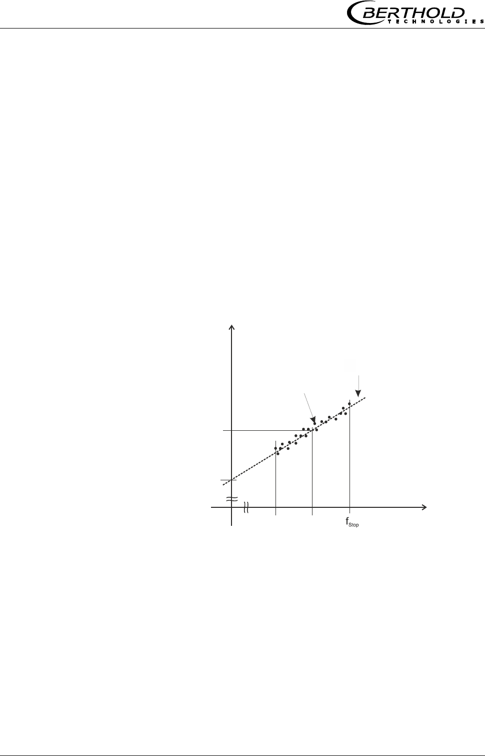
Chapter 3 Software Functions
18 MicroPolar Moist LB 568
3.2.10 Phase Measure
The phase and attenuation are calculated for each measured
value (measuring cycle) from a multitude of single
measurements of different frequencies in a wide frequency
band (called sweep/frequency sweep). Such a measurement
permits a continuous verification of the plausibility of the
results of a measurement.
The size of the frequency range allows you to select a belt to
possibly rule out strong interferences (for example due to
reflection) from the start. The frequency selection is done
manually on the menu | SETUP | CONFIGURATION |
MICROWAVE. As a rule, the frequency band "Standard" (this
is the factory setting) is a good choice.
The attenuation calculation takes place through averaging via
the frequency range, without further plausibility check.
The phase calculation takes place through regression
calculation via the frequency range, followed by a plausibility
check (see the illustration below).
Phase [DEG]
Frequency [GHz]
fStart fm
Regression line
Frequency points
Phi Offset
Phi(f=fm)
The phase check is always done through Sigma max and a
second selectable plausibility of Phi Offset max or Phi/Att
ratio. A combination of Phi Offset and Phi/Att ratio is not
possible.
If Sigma max or Phi Offset max is exceeded, then the
measurement is rejected. If the exceeding occurs
continuously exceeded, the evaluation unit changes to the
error state. The time up to when the fault is triggered is 75%
of the averaging time of the mean concentration value.
In the factory state, the plausibility is adjusted via Phi Offset;
this is recommended for all applications.

Chapter 3 Software Functions
MicroPolar Moist LB 568 19
Phi offset max:
Phi Offset is the phase value where the frequency is zero
(see illustration above).
Here the maximum permissible value is entered for Phi
Offset. Typical values between 150 to 170°. Default: Phi
Offset max. = 170°.
With Phi Offset max = 0 the plausibility is turned off.
Sigma max.:
Here you set the maximum sigma of the regression Phase
vs. Frequency.
During normal measurement operation, the scattering lies
between 0 and 300. Default: Sigma = 500. With sigma =
0, the plausibility is turned off.
Phi/Att ratio:
The ratio of phase and attenuation is used for the phase
check. A fixed Phi/Att ratio is entered. If you do not know
it, you have to record it once, see the description for
"Auto set" below. The exact procedure is described in
chapter 6.1.
The phase check is done as follows:
m
measpermitted f
180
DV
Eg. 3-1
Where:
permitted = permitted phase range
V = parameter Phi/Att
Dmeas = measured attenuation
fm = center frequency
If the phase is not in this range, it is corrected by
360°/fm.
Default: Phi/Att = 0
The Phi/Att ratio can be enabled and disabled.
Auto set:
The automatic ratio measurement Phi/Att can be turned
on and off. For details see chapter 6.3.
1 | - | Phase Measure | 07.05 – 13:25
Phi offset max 170°
Sigma max. 500
Phi/Att Disabled
Phi/Att ratio 0
Auto set OFF
⌂◄ ▲ ▼ ►
Chapter 3 Software Functions
20 MicroPolar Moist LB 568
3.2.11 Synchronization
If compensation measurements are carried out in a large
distance from the microwave measuring path, then the
current input signals (compensation signals) can be stored
temporarily and can be synchronized with the microwave
information. The goal of the synchronization is to make sure
that all measuring information of all systems relate to the
same product section.
Please see the measuring conditions described in chapter 7.3
in the Hardware Manual.
Variable conveying speed: Only one current input signal can
be synchronized because current input 2 is used for the belt
speed. The speed signal must be fed in via current input 2
and m/s has to be selected as the unit for current input 2.
Sync. config.:
Select the synchronization mode and, if necessary, enter
the conveying speed.
Current input 1/2:
Enter the distance between compensation measurement
(for example, belt weigher) and microwave
measurement. If the compensation measurement is
installed before the microwave measurement, relative to
the conveyor belt direction, enter a positive distance;
otherwise, enter a negative distance.
The submenus CURRENT INPUT 1 and CURRENT INPUT 2
are displayed only if the current inputs and
synchronization have been enabled.
Mode:
Disable
Constant speed
Variable speed
The item "Variable velocity" is displayed only if m/s has
been selected as the unit for current input 2.
Velocity:
Enter the conveyor belt speed in m/s.
This menu appears only if the mode "Constant velocity" is
selected.
1 | - |Synchronization| 07.05–13:25
Sync. config.
Current input 1
Current In 2
⌂◄ ▲ ▼ ►
1 | - |Sync. config | 07.05–13:25
Mode
Velocity
⌂◄ ▲ ▼ ►
Chapter 3 Software Functions
MicroPolar Moist LB 568 21
3.2.12 Calibration
System adjust:
System calibration is started here.
Calibrate conc:
Opens the calibration menu of concentration 1.
Calibrate conc 2:
Opens the calibration menu of concentration 2.
The second concentration is displayed only if under menu
| ADCANCED | PROCESS TYPE | a second concentration is
selected.
Advanced:
Here you set the tare values, the number of sweeps, the
process type, the split value and the extended calibration
mode. For details see chapter 3.2.17 Advanced.
3.2.13 System Adjust
Adjust:
System calibration is started.
Reference values:
Upon completion of the reference measurement, the
reference values for phase (Phi(fm)), attenuation, slope
and sigma can be output.
Chart Phi:
Shows the phase values versus the frequency.
Chart Attenuation:
Shows the attenuation versus the frequency.
The data log will not be deleted by a system calibration (see
chapter 3.2.2 Diagnostic).
1 | - | Calibration | 07.05 – 13:25
System adjust
Calibrate Conc
Calibrate Conc 2
Advanced
⌂◄ ▲ ▼ ►
1 | - |System Adjust | 07.05 –13:25
Adjust
Reference values
Chart Phi
Chart Attenuation
⌂◄ ▲ ▼ ►

Chapter 3 Software Functions
22 MicroPolar Moist LB 568
3.2.14 Calibrate Concentration
Sampling:
Shows all measured samples and entered lab values.
Calibration:
Here you can choose the calibration order
[linear/quadratic], the basis [phase/attenuation or both]
and the compensations.
For details please see chapter 3.2.18 Calibration.
Select Calibration to enable and parameterize the
temperature and loading compensation.
Select Calibration to carry out the automatic calculation
of the coefficients.
Tuning:
Subsequent correction of the reading is possible by
entering a factor and an offset.
Calculation is carried out using the following formula:
OffsetFactorDisplay display Corrected
Eg. 3-2
View:
Presentation of calibration curve, display of correlation
and coefficients.
1 | - | Calibrate Conc | 07.05 –13:25
Sampling
Calibration
Tuning
View
⌂◄ ▲ ▼ ►

Chapter 3 Software Functions
MicroPolar Moist LB 568 23
3.2.15 Sample Table
The header includes the following information (from left to
right):
Product no.
Current table position / Total number of entries
Sample no. of current table position
Date and time of sampling
Up to 20 sample entries are possible. The sample can be
assigned to the lab value either via the sample no. or
through data/time. The sample no. is assigned on a
continuous basis. If a sample is deleted, the sample no. will
not be assigned a second time. Up to 999 sample numbers
are available. Only if all numbers have been assigned, you
may assign a number for the second time; you will be alerted
accordingly on the display.
Next sample:
Continues with the next sample.
Active:
Here you can choose if this sample should be taken into
account in the calibration.
Measured value:
Display of the measured values, calculated with the
actual coefficient.
Lab value:
Entry position for the laboratory value.
Extended:
Switches to the next data page.
Delete:
Briefly push the softkey to delete the indicated sample
entry. Push this key for a longer time to delete all sample
entries.
1 | 1/1 | Sample # 1 | 07.05 –13:25
Next sample
Active Yes
Measured value 65.50%
Lab value 0.00 %
Extended
◄ DEL ▲▼ ..√..
Chapter 3 Software Functions
24 MicroPolar Moist LB 568
3.2.16 Sample Data (expanded)
Current In 1:
Display of the first compensation input (editable)
Current In 2:
Display of the second compensation input (editable)
PT100:
Display of the PT100 input (editable)
PHI (fm):
Display of the measured phase.
Attenuation:
Display of the measured attenuation.
MPUA loading
Displays the measured load [g/cm2]
3.2.17 Advanced
Tare values:
Option to enter tare values for phase and attenuation.
The tare values are added to the phase stage and/or the
attenuation prior to calibration. The calculation is carried
out as follows:
Eg. 3-3 and 3-4
Phase = Phasemeas - Phi Tare
Attenuation = Attenuationmeas - Attenuation Tare
Number of calibration sweeps:
Freely adjustable number of sweeps over which a
calibration point (in the course of automatic sample
measurement) will be averaged.
Process type:
Select the operation mode:
one concentration [1 measuring range]
two concentrations [2 measuring ranges]
split concentration [1 measuring range with switching
point (split value) for coefficient switchover].
Split value:
Setting of the switching point on a value basis.
Extended calibration mode:
Details see chapter 6.4.6.
1 | - | Advanced | 07.05 – 13:25
Tare values
Num. cal. sweeps 20
Process type Split conc
Split value 75.00 %
Extended cal. mode disabled
⌂◄ ▲ ▼ ►
1 | 1/1 | Sample # 1 | 07.05 –13:25
Current In 1
Current In 2
PT100
PHI (fm)
Attenuation
MPUA loading
◄ DEL ▲▼ ..√..

Chapter 3 Software Functions
MicroPolar Moist LB 568 25
3.2.18 Calibration
Cal. order
Here you define the calibration order [linear / quadratic]
Default: Linear
Cal. base
The following parameters can be set:
Phase
Attenuation
Phase and attenuation
Default: Attenuation
Coefficients:
Here you can edit all coefficients for phase and
attenuation.
Default: A1 = 0, B1 = 0, C = 10
Temp. comp.:
If at least one analog input is active, you may here assign
the compensation and set the compensation parameters.
For details please see chapter 3.2.19 Temperature
Compensation.
Loading comp.
If at least one analog input is active, you may here assign
the compensation and set the compensation parameters.
For details please see chapter 3.2.20 Load Compensation.
Start Calibration
Starts the calibration using the parameters you have set
earlier.
1 | - | Calibration | 07.05 –13:25
Cal. order
Cal. base
Coefficients
Temp. comp.
Loading comp.
Start Calibration
⌂◄ ▲ ▼ ►

Chapter 3 Software Functions
26 MicroPolar Moist LB 568
3.2.19 Temperature Compensation
Input:
The compensation can be turned on and off: if no input is
selected, the compensation is turned off.
An analog input is assigned to the compensation (current
input 1/2, PT100); only the activated inputs are available.
Mode:
The following parameters can be set:
Additive
Multiplicative
Order:
The following parameters can be set:
Linear
Quadratic
TC evaluation:
The following parameters can be set:
Sampling
The temperature coefficients are calculated using the
entries in the sample table.
User-defined
The temperature coefficients are defaulted, for
example, if they are already known from other
applications.
Default: Sampling
Reference value
Enter the reference value.
C_dB 1:
All temperature coefficients are listed depending on the
previously defined compensation parameters. They can
be edited and/or read off here after execution of a
calibration calculation with "Start calibration".
See additional explanation in the Hardware Manual in chapter
7.2 Temperature Compensation.
1 | - | Temp. Comp. 1 | 07.05 –13:25
Input
Mode
Order
TC evaluation
Reference value
C_dB 1
⌂◄ ▲ ▼ ►
Chapter 3 Software Functions
MicroPolar Moist LB 568 27
3.2.20 Loading Compensation
At least one analog input or the radiometric detector must be
active so that the LOADING COMPENSATION menu is
displayed. Some compensation modes are displayed only
upon activation of two inputs.
Comp. mode:
The following parameters can be set:
Disabled / Enabled
Radiom. MPUA
Loading (Current In 1)
Tonnage & Speed
Mass & Layerheight
If the loading compensation is selected, the Loading Limit
menu appears.
Loading limit:
Enter the minimum load; if this value is not reached, the
evaluation unit switches to the error state.
Compensation mode Loading (Current In 1):
The following units can be used as a compensation signal:
Weight
Layer height
Mass per unit area
Throughput
Signal input via current input 1
The unit can be selected at random for current input 1.
1 | - | Load Comp | 07.05 –13:25
None
Radiom. MPUA
Loading (Cin 1)
Tonnage & Speed
Mass & Layerheight
⌂◄ ▲ ▼ ►
1 | - | Load Comp | 07.05 –13:25
Comp. mode Height
Loading limit
⌂◄ ▲ ▼ ►

Chapter 3 Software Functions
28 MicroPolar Moist LB 568
Compensation mode Tonnage & Speed
(throughput & speed):
Signal input
Throughput via current input 1
Speed via current input 2
Unit
Throughput [tons per hour; T/h]
Speed [m/s]
Min. load [Kg]
The unit T/h must be selected for current input 1 and the
unit m/s for current input 2.
Compensation mode Mass & Layerheight
(weight & layer thickness):
Signal input
Weight via current input 1
Layer thickness via current input 2
Unit
Weight [Kg]
Layer thickness [cm]
Min. load [kg x cm]
The unit kg must be selected for current input 1 and the
unit cm for current input 2.
Compensation mode Radiometric MPUA:
The compensation signal is provided by the scintillation
counter.
Unit
Mass per unit area [g/cm2]
Min. load [g/cm2]
See additional explanation in the Hardware Manual, chapter
3.3 Loading Compensation.
Chapter 3 Software Functions
MicroPolar Moist LB 568 29
3.2.21 Inputs / Outputs
Current output:
Both outputs can be adjusted, assigned and set up on the
selected level.
Current input:
Activation level of current input, calibration and display of
the live current signal.
PT100:
Here you can enable and adjust a connected PT100.
Display of the actual temperature signal.
Digital output:
Allocation of relays 1 and 2 and test function.
Digital input:
Status control and assignment of the digital inputs.
3.2.22 Current Output
IMPORTANT
If a measurement is running, enabling a non-used or
non-adjusted current input may cause an error.
3.2.23 Current Out 1
Assignment:
The following signals can be assigned to the current
output.
None
Concentration
Concentration 2 (if active)
Mass per unit area (if active)
Current input 1 or 2 (if active)
PT100 (if active)
1 | - | Inputs/Outputs | 07.05 –13:25
Current output
Current input
PT100
Digital output
Digital input
⌂◄ ▲ ▼ ►
1 | - | Current Output | 07.05 –13:25
Current out 1
Current out 2
⌂◄ ▲ ▼ ►
1 | - |Current Out 1 | 07.05 –13:25
Assignment
4 mA
20 mA
Test/Adjust
Error current
⌂◄ ▲ ▼ ►
Chapter 3 Software Functions
30 MicroPolar Moist LB 568
4 mA:
Display value assigned to the 4mA value.
20 mA:
Display value assigned to the 20mA value.
TIP
Current output 1 only 4 – 20mA possible
If the current output limit is exceeded, then the
measurement changes to the warning status, see section
8.4 Device States.
Test/Adjust:
Current test, calibration and display of live current.
The ADJUST menu is displayed only in the Profi mode.
IMPORTANT
The measurement should be stopped for test function.
To check the current loop and possibly connected remote
displays, you can set a current between 4 and 20 mA via
the test function. If you quit the test function, the system
automatically switches back to the live current.
Error current:
If the measurement goes into the error state, a fault
current is output via the current output; this fault current
can be set here.
22 mA
3.5mA
Hold
Value (selectable)
3.2.24 Current Out 2
All functions same as current output 1
TIP
Current output 2 can either be set to 0/4 or to 20 mA.
Range:
Change the current output
0 – 20mA
4 – 20mA
1 | - |Current Out 2 | 07.05 –13:25
Assignment
4 mA
20 mA
Range
Test/Adjust
Error current
⌂◄ ▲ ▼ ►
Chapter 3 Software Functions
MicroPolar Moist LB 568 31
3.2.25 Current Input
Current in 1:
When selected, the program changes to the activation
and calibration menu.
Current in 2:
As described above.
3.2.26 Current In 1
Status:
Select yes/no to enable or disable the current input.
Range:
Change the current output
0 – 20mA
4 – 20mA
0/4 mA:
Display value assigned to the 0/4 mA value.
20 mA:
Display value assigned to the 20mA value.
Adjust:
Follow the instructions on the display.
Live current:
Display of the live current signal.
3.2.27 Current In 2
Settings correspond to current input 1.
1 | - | Current Input 1 | 07.05 –13:25
Status
Range
4 mA
20 mA
Adjust
Live current
⌂◄ ▲ ▼ ►
1 | - | Current Input | 07.05 –13:25
Current in 1
Current in 2
⌂◄ ▲ ▼ ►

Chapter 3 Software Functions
32 MicroPolar Moist LB 568
3.2.28 PT100
Enabled:
If a PT100 is connected, the input has to be enabled first.
IMPORTANT
If a measurement is running, enabling a non-used or
non-adjusted PT100 input may cause an error.
Adjust PT100:
You need a 100 Ohm and a 138.5 Ohm resistance. Follow
the instructions on the display.
PT100 live:
Display of the live temperature.
Settings correspond to input 1.
1 | - | Pt 100 | 07.05 –13:25
Enabled
Adjust PT100
PT100 live
⌂◄ ▲ ▼ ►
Chapter 3 Software Functions
MicroPolar Moist LB 568 33
3.2.29 Digital Output
The measuring device has two relays. Relay 1 is linked with
LED signal 1 and relay 2 with signal 2.
Relay 1:
Different functions can be assigned to relay 1:
None
Error
Hold
Alarm min.
Alarm max.
Function
Description
None
Relay and LED function disabled
Error
In case of error, relay and LED will be set.
Hold
If Hold function is enabled, relay and LED
will be set.
Alarm min.
The relay switches if the value falls below
the limit value to be set.
Alarm max.
The relay switches if the value exceeds
the limit value to be set.
Relay 2:
Same assignments possible as above.
Test:
The switching status of the relays can be set here and
checked at the respective terminals.
3.2.30 Digital Input
The measuring device has 3 digital inputs, to which different
functions can be assigned.
Status:
Shows the status of the input circuit
open/closed
1 | - | Digital Output | 07.05 –13:25
Relay 1
Relay 2
Test
⌂◄ ▲ ▼ ►
1 | - | Digital Input | 07.05 –13:25
Status
DI 1 function
DI 2 function
DI 3 function
⌂◄ ▲ ▼ ►
Chapter 3 Software Functions
34 MicroPolar Moist LB 568
DI 1 Function
The following functions can be assigned to DI 1:
None
Start (external start)
DI 2 Function
The following functions can be assigned to DI 2:
None
Hold (averaging is stopped)
Product (external product selection)
DI 3 Function
Assignments for DI 3:
None
Sample (external control of sampling)
Product (external product selection)
For external start function, the start function has to be set to
external in the Measurement menu window.
Hold means that averaging is stopped, but the measurement
continues to run.
Sample means that sampling is started by closing the
contact.
Product means that another product is selected by closing
the contact (product 1 to 4).
TIP
If you select a product for the first time (product 2 to 4),
all settings and contents of the current product will be
copied to the new product, including:
- Configuration data
- System calibration
- Calibration data (including sampling table)
- Input/Output definitions
To switch over all 4 products, DI 3 also has to be set to
product. Please take the terminal configuration from the
table below.
Terminals
DI 2
13 / 25
DI 3
14 / 26
Product 1
open
open
Product 2
closed
open
Product 3
open
closed
Product 4
closed
closed

Chapter 3 Software Functions
MicroPolar Moist LB 568 35
3.2.31 Service
Factory setting and General reset:
See table on the next side.
The Factory setting function allows you to reset the
measuring system parameters to their original status.
Memory tool:
Refers to the communication with the external memory
stick (optional accessory). Data transfer takes place via
the 9-pole SubD-connector on the bottom of the
instrument.
Save parameters: All instrument parameters for all
products will be saved to the memory stick.
Load parameters: All instrument parameters stored
on the memory stick will be loaded onto the
evaluation unit. All operating parameters in the
evaluation unit will be deleted.
Save data log: The data log will be saved to the
memory stick.
Save log: The start-up log will be saved to the
memory stick.
The concentration average value is put on hold during
communication with the memory stick. Thus, the measured value
via current output is also put on hold!
Data printout:
All measured values are output for each measurement
(sweep) via the serial data interface RS232. The output
can be set as follows:
None (disabled)
Line (data transfer, see Hardware Manual, chapter
6.6)
Table (microwave data for each frequency point)
Line and table
"Line" is defaulted.
1 | - | Service | 07.05 – 13:25
Factory settings
General reset
Radiom. detector
Memory tool
Data printout Line
⌂◄ ▲ ▼ ►

Chapter 3 Software Functions
36 MicroPolar Moist LB 568
Factory setting
General reset
Language selection
unchanged
unchanged
Access level
unchanged
default: Basic
Measurement
is stopped
is stopped
Password
unchanged
default: PASS1
Product selection
unchanged
all products deleted
Error log
not deleted
deleted
Data log
not deleted, default
settings
deleted, default
settings
System adjust
not deleted
deleted
Cable length
unchanged
default
Sampling
not deleted
deleted
TAG label
default
default
All parameters on menu:
Measurement
Plausibility
Marker
Unit
default
default
Frequency setting
unchanged
unchanged
Calibrate coefficients
default
default
Temperature compensation
default
default
Load compensation
default
default
All settings for the analog
and digital inputs and
outputs
default
default
Adjustment of the analog
inputs and outputs
unchanged
unchanged
Comment:
affects only the
current product
affects all products (P1
to P4)
-
*Default: Default values, see chapter 9.1 Example Start-up Log
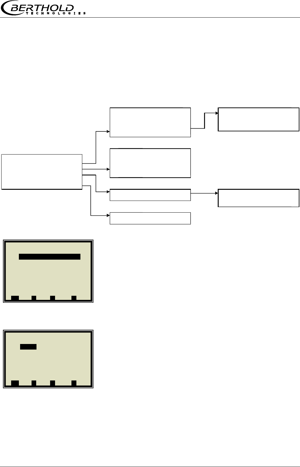
Chapter 3 Software Functions
MicroPolar Moist LB 568 37
3.3 Menu Structure Radiometric Detector
3.3.1 Configuration Radiometric Detector
Starting from the main menu, you can reach the following
menu via | SETUP | Configuration | Radiometry |
Enabled (Yes/No)
With this selection, the radiometric mass per unit area
compensation of the evaluation unit is turned on or off.
If this item is disabled, no radiometry parameters can be set
(hidden).
If it is enabled, the live data is requested by the detector.
Errors occurring with respect to the radiometry will be
displayed even if the measurement has been stopped.
Calibration
Configuration of the Io recording (zero count rate); the
following parameters can be configured:
• Max adjust time (duration of Io recording)
• Io (current Io value)
• Isotope (Cs137 and Am241 selectable)
• Ray angle (radiometry)
If the irradiation path in the product is of different length in a
microwave and radiometric measurement, this must be
considered using the "Ray angle."
Enter an angle of 30° for applications in the measuring
chute.
Calibration
Isotope
Adjust
Isotope
Max. adjust time
180 s
I0
3 cps
CS137
Isotope
CS137
AM241
Ray angle
0.00°
Detector live
Actual impulse rate
11555 cps
Enabled
yes/no
Average impulse rate
11550 cps
Calibration
Current temperature
22.6°C
Detector live
Actual HV
500 V
Measurement
HV control mode
Manual
Plausibility
MPUA calculation
Plausibility
Counting rate band
Counting rate band
Validation
activated
Max. detector temp.
50.00 °C
Max. counting rate
100000 cps
Min. counting rate
0 cps
MPUA calculation
MPUA actual
0.00 g/cm^2
Absorption coeff.
0.07
1 | - | Radiometry | 07.05 – 13:25
Enabled yesg
Calibration
Detector live
Measurement
Plausibility
MPUA calculation
⌂◄ ▲ ▼ ►
1 | - | Calibration | 07.05 – 13:25
Adjustg
Max adjust time 180s
I0 3 cps
Isotope CS137
Ray angle 0.00 °
⌂◄ ▲ ▼ ►
Chapter 3 Software Functions
38 MicroPolar Moist LB 568
Adjust (Io recording)
The Io value can be entered directly or it can be recorded via
the ADJUST menu.
The Io recording can be started or stopped on the ADJUST
menu. The Io recording is possible only in the STOP mode of
the evaluation unit. The progress of Io recording is
represented by a moving circle. The prerequisite is that the
detector does not report an internal error and that the
communication between evaluation unit and the detector is
in order.
Detector live
Here the actual, averaged count rate, actual temperature
(detector), actual HV and HV control mode are displayed. All
parameters are only displayed here and cannot be edited.
Measurement
Here, the averaging of the count rate can be adjusted. The
evaluation unit uses only the averaged pulse rate (CPSa) for
calculating the mass per unit area.
The averaging (moving average) takes place via the entered
number of measurements.
Default: 10
Plausibility / Counting rate band
With these parameters, the current count rate from the
detector can be checked for a valid range. If the count rate is
out of range, then the evaluation unit goes to the error state.
The following parameters are available
• Validation (enabled/disabled)
Default: enabled
• Max. counting rate, default: 100000
• Min. counting rate, default: 0
MPUA calculation
Input option absorption coefficient, default value: 0.07
The MPUA is displayed on the menu only if the loading
compensation (radiometry) is enabled.
If the evaluation unit is in the RUN mode, then the MPUA is
calculated and shown on the menu.
If the evaluation unit is in the STOP mode, then the MPUA is
not calculated and 0.0 g/cm² shown on the menu.
1 | - | Measurement | 07.05 – 13:25
Averaging (CPS) 10g
⌂◄ ▲ ▼ ►
1 | - | Detector live | 07.05 – 13:25
Actual impulse rate 55 cpsg
Average impulse rate 53 cps
Actual temperature 25.2°C
Actual HV 430 V
HV control mode Auto
⌂◄ ▲ ▼ ►
1 | - |Counting rate band| 07.05 – 3:25
Validation enabledg
Max. counting rate 100000 cps
Min. counting rate 0 cps
⌂◄ ▲ ▼ ►
1 | - | MPUA calculation | 07.05 – 3:25
MPUA live 0.00 g/cm3
Absorption coeff. 0.07
⌂◄ ▲ ▼ ►
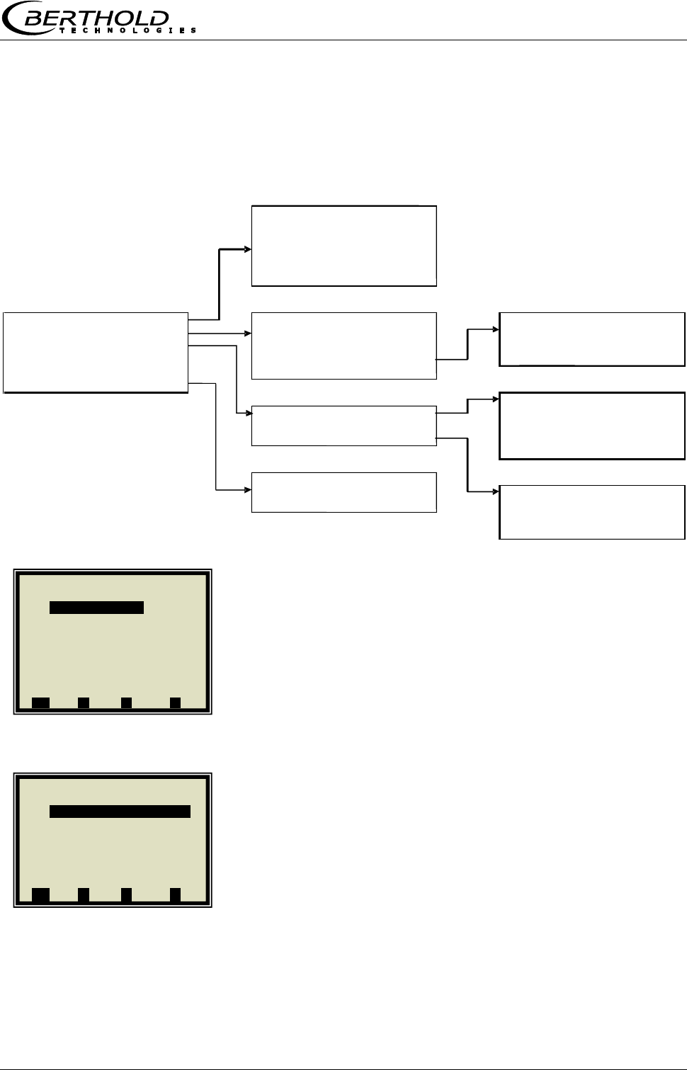
Chapter 3 Software Functions
MicroPolar Moist LB 568 39
3.3.2 Service Radiometric Detector
Starting from the main menu, you can reach the following
menu via | SETUP | Services | Radiom. Detector |
Detector errors
The menu shows the current detector error with the following
additional information:
• Error Id
• Error date
• Error time
• Error priority
With "Acknowledge error", the error in the detector is
acknowledged.
HV setup (HV = high voltage)
Here, the HV control can be configured.
• HV actual (read only, current HV in the detector current)
• HV manual (write, fixed value for the HV control mode
manual)
• HV default (write, value where the HV control mode
automatically starts to control)
• Actual impulse rate (read only)
Detector errors
Acknowledge error
Actual error
none
Error descriptor
0
Error date
--
Error time
--
Error priority
-1
HV setup
HV control mode
Detector errors
HV actual
525.0 V
HV control mode
HV setup
HV manual
525.0 V
Plateau
HV default
525.0 V
Automatic
Factory reset
HV control mode
Manual
Manual
Detector reset
Actual impulse rate
125 cps
Info
Plateau measure
Plateau
Plateau time
10s
Plateau measure
Plateau stop
800 V
Operating point setup
Plateau start
400 V
Plateau charts
Plateau step
25 V
Measure plateau
Info
Software version
1.2.1
Plateau charts
Unique ID
1563256845
Plateau date
11.11.2010
Detector code
Plateau time
15:18
Chart plateau
Print plateau
1 | - |Detector errors| 07.05 –13:25
Acknowledge error
Actual error --
Error descriptor -1
Error date --
Error time --
Error priority -1
⌂◄ ▲ ▼ ►
1 | - |HV setup| 07.05–13:25
HV actual 420.0 V
HV manual 420.0 V
HV default 430.0 V
HV control mode autom.
Actual impulse rate 55 cps
⌂◄ ▲ ▼ ►
Chapter 3 Software Functions
40 MicroPolar Moist LB 568
Plateau / Plateau measure
• Plateau time (how long is the measurement done on one
HV point)
• Plateau stop (HV final value)
• Plateau start (HV start value)
• Plateau step, e.g. 25 V
• Measure plateau (detector starts recording the plateau,
shows a progress bar)
Plateau / Operating point setup
• Set operating point (if no plateau is present, the message
"Error! Canceled" is displayed)
Plateau / Plateau charts
• Plateau date: read only, date the plateau was recorded, if
no plateau has been recorded, 01.01.2000 is displayed.
• Plateau time: read only, time the plateau was recorded, if
no plateau has been recorded, 00:00 is displayed.
• Chart plateau: shows the plateau in a chart if the HV
range is 300 V to 1200 V, for example, only a range of
400 V to 800 V is shown in the chart.
• Print plateau: the plateau can be printed via the RS232.
Factory reset
This function resets the detector to factory settings.
Detector reset
This function starts the detector new.
Info
• Software version (detector)
• Unique ID (detector)
• Detector code (e.g. CsI40/50)
1 | - | Plateau | 07.05 – 13:25
Plateau measure
Operating point setup
Plateau charts
⌂◄ ▲ ▼ ►
1 | - | Plateau charts | 07.05 – 13:25
Plateau date 01.10.2012g
Plateau time 00:00
Chart plateau
Print plateau
⌂◄ ▲ ▼ ►
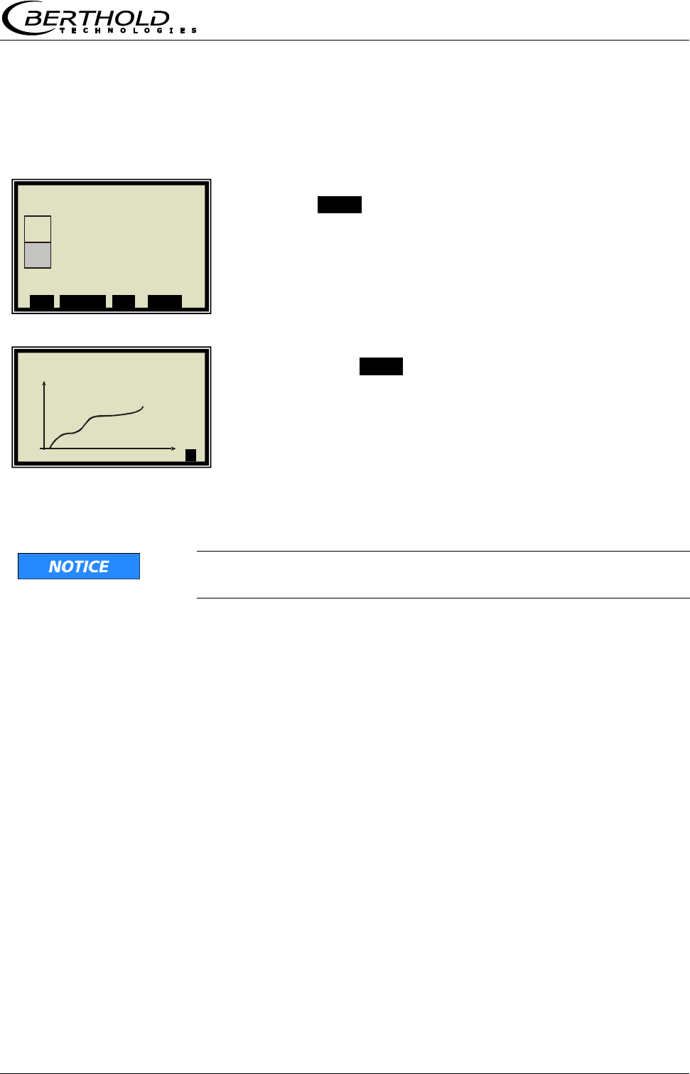
Chapter 3 Software Functions
MicroPolar Moist LB 568 41
3.4 Live Display
Push the ZOOM button to enlarge the measurement value
which is surrounded by a frame.
By pushing the ZOOM button for a longer time, the enlarged
measurement value will be displayed as trend over the entire
display.
The trend display corresponds to the contents of the data
log. The data log has to be enabled for the trend display.
As long as the trend builds up, the measured value and/or the
current output are put on hold!
| | Concentration av. |
%
MIN
►
1 | - | Live Display | 07.05 – 13:25
Concentration av.
43.20 %
Conc. av. Conc. act. Act.45 %
ESC SAMPLE ▲▼ ZOOM
Chapter 4 Configuration
42 MicroPolar Moist LB 568
Chapter 4. Configuration
Before carrying out any calibration work, the required analog
inputs and the radiometric detector have to be enabled and
configured, and the configuration parameters have to be
checked and corrected, if necessary.
Without activation of the required inputs, some menus are
not displayed and a proper configuration and calibration will
not be possible. The current outputs, digital outputs can be
enabled and configured after the calibration.
The measuring system includes two separate floating current
outputs.
Note: The measuring system has been connected properly
and the normal operating temperature has been reached
(approx. 45 min. acclimatization).
4.1 Configuration Setup
Starting from the main menu, you get in the Profi mode to
the display to the left by selecting | SETUP |
CONFIGURATION
4.1.1 General Data
GENERAL DATA
1 | - | Configuration | 07.05 – 13:25
General Data
Measurement
Plausibility
Microwave
Radiometry
Marker
Units
Synchronization
⌂◄ ▲ ▼ ►
1 | - | Setup | 07.05 – 13:25
Configuration
Calibration
Input / Output
Service
Product
Change password
⌂◄ ▲ ▼ ►
Chapter 4 Configuration
MicroPolar Moist LB 568 43
Example:
Select the respective entry, edit and store it.
DATE
Push DEL to delete the entry and then enter the new date.
Push .√. to confirm and store the changed date.
TIP
The colon for the time input (e.g. 13:25) is invoked by
pushing the button [ . ].
4.1.2 Measurement
You have to check the settings on this display and adapt
them to the measurement conditions.
For example, you have to adapt the measurement mode, the
start mode and the averaging to the actual operating
conditions.
4.1.3 Plausibility
Adjust the process limits. Allow for an absolute measuring
overrange of ± 3%.
Example: The measurement range is 5 -10% moisture. Enter
2 -13% moisture as process limits.
The process limits are independent of the current output
limits.
For details on the phase measurement, see chapter 4.3
Configuration Plausibility.
1 | - | General Data | 07.05 – 13:25
Date 07.05.2004
Time 13:25
Tag App.1
⌂◄ ▲ ▼ ►
1 | - | General Data | 07.05 – 13:25
Date
07.05.2004 |
ESC ..?.. DEL ..√..
1 | - | Measurement | 07.05 – 13:25
Meas. mode Continuous
Start mode Keypad
Averaging 20
Reset averaging no
⌂◄ ▲ ▼ ►
1 | - | Plausibility | 07.05 – 13:25
Process limits
Phase measure
⌂◄ ▲ ▼ ►
Chapter 4 Configuration
44 MicroPolar Moist LB 568
4.1.4 Microwave/Cable
CABLES
If the factory-set cable lengths do not match the actual
geometry conditions, you have to correct the values.
Example: For 1.5 and 2.5 m long antenna cable and 4 m
reference cable, you have to enter 4 m for both lengths.
1 | - | Microwave | 07.05 – 13:25
Cables
Frequency
⌂◄ ▲ ▼ ►
1 | - | Cables | 07.05 – 13:25
Ref. cable length 4 m
Signal cable length 4 m
⌂◄ ▲ ▼ ►
Chapter 4 Configuration
MicroPolar Moist LB 568 45
4.1.5 Configuration Radiometry
Configure the detector by selecting it.
Starting from the main menu, you get in the Profi mode to
the display to the left via
| SETUP | CONFIGURATION | RADIOMETRY |
ENABLED
Enable the detector here.
Then go to the measurement.
MEASUREMENT
The averaging number for the count rate can be adjusted
depending on the application. For applications where the
mass per unit area changes only slowly, the averaging
number can be increased to 30.
4.1.6 Marker
You can set a marker comprising max. 5 characters which
identify the value set in the live display.
MARKER
1 | - | Configuration | 07.05 – 13:25
General Data
Measurement
Plausibility
Microwave
Radiometry
Marker
Units
Synchronization
⌂◄ ▲ ▼ ►
1 | - | Radiometry | 07.05 – 13:25
Enabled no
Calibration
Detector live
Measurement
Plausibility
MPUA calculation
⌂◄ ▲ ▼ ►
1 | - | Measurement | 07.05 – 13:25
Averaging (CPS) 10
⌂◄ ▲ ▼ ►
Chapter 4 Configuration
46 MicroPolar Moist LB 568
4.1.7 Units
Set the units as desired.
UNITS
The units of the concentrations (conc 1 and 2) and those of the
enabled analog inputs can be selected.
CONC / CONC 2
%
Different units can be set for both concentrations.
CURRENT IN 1
°C
The selection of the units for current input 1 and 2 are different.
This depends on the fixed assignment of the current inputs for
loading compensation.
1 | - | Configuration | 07.05 – 13:25
General Data
Measurement
Plausibility
Microwave
Radiometry
Marker
Units
Synchronization
⌂◄ ▲ ▼ ►
1 | - | Units | 07.05 – 13:25
Conc % DS
Conc 2 %
Current input 1 °C
Current input 2 m/s
Temp. PT100
⌂◄ ▲ ▼ ►
1 | - | Units | 07.05 – 13:25
Conc.
None
Specific
%
% DS
ESC ..?.. ▲▼ ..√..
.
1 | - | Units | 07.05 – 13:25
Conc % DS
Conc 2 %
Current input 1 °C
⌂◄ ▲ ▼ ►
1 | - | Units | 07.05 – 13:25
Current input 1
None
Specific
°C
°F
g/cm^2 …
ESC ..?.. ▲▼ ..√..
Chapter 4 Configuration
MicroPolar Moist LB 568 47
4.2 Start Calibration Coefficients
Starting from the main menu, you get in the Profi mode to
the display to the left by selecting:
| SETUP | CALIBRATION | CALIBRATE CONC |
CALIBRATION
COEFFICIENTS
The concentration is calculated as follows.
Con = B1∙D + C with D = attenuation
Check the coefficients B1 and C and correct them, if
necessary, as follows:
C = medium measuring range value (concentration value)
B1 = 0
Note: With these calibration coefficients the concentration
average value and thus the current output is put on hold during
start-up.
1 | - | Calibrate Conc | 07.05 –13:25
Sampling
Calibration
Tuning
View
⌂◄ ▲ ▼ ►
1 | - | Calibration | 07.05 – 13:25
Cal. order Linear
Cal. base PHI
Coefficients
Temp. comp.
Loading comp.
Start calibration
⌂◄ ▲ ▼ ►
1 | - | General Data | 07.05 – 13:25
B1 0
C 10
⌂◄ ▲ ▼ ►
Chapter 4 Configuration
48 MicroPolar Moist LB 568
4.3 Configuration Plausibility
As described in chapter 3.2.10 Phase Measure, the
plausibility via Phi Offset is preferred for all applications.
Starting from the main menu, you get in the Profi mode to
the display to the left by selecting:
| SETUP | CONFIGURATION | PLAUSIBILITY | PHASE
MEASURE |
The display to the left shows the default settings; these may
have to be entered, if necessary.
A subsequent restriction of Phi Offset max and Sigma max
may be useful in order to eliminate phase jumps. The
following adjustment ranges are recommended:
Phi Offset max.: 150° - 170°
Sigma max: 50 - 500
If a phase jump elimination is not possible, then either an
attenuation calibration (preferably with conveyor belts) has
to be carried out, or the plausibility has to be determined via
the behavior of Phi/Att, see chapter 6.1 Phi/Att ratio.
Setup of an attenuation calibration:
Starting from the default values (see display on the left) Phi
Offset max must be set to 0. Sigma max should be set
roughly, so that various problems can be ruled out.
1 | - | Phase measure | 07.05 – 13:25
Phi offset max. 170.00°
Sigma max 500.00
Phi/Att Disabled
Phi/Att ratio 0.00
Auto set OFF
⌂◄ ▲ ▼ ►
Chapter 5 Calibration
MicroPolar Moist LB 568 49
Chapter 5. Calibration
Prerequisite: chapter 4. Configuration
has been completed.
5.1 Scintillation Counter Calibration
Calibration is performed by recording the zero count rate I0
(adjustment).
For this purpose, the belt or the chute must run empty, clean
and dry.
For a belt, the I0 recording has to take place over at least an
entire belt cycle. For example, belt speed 2 m/s, conveyor belt
length 100 m:
belt cycle = 2 * conveyor belt length
Thus, min. recording time = 200 m / 2 m / s = 100 s
Starting from the main menu, you get in the Profi mode to
the display to the left via | SETUP | CONFIGURATION |
RADIOMETRY | CALIBRATION |
Before the calibration, the parameters (default values) listed
in the display to the left must be changed as needed. Details
see chapter 3.3.1 Configuration Radiometric Detector.
ADJUST
TIP
Calibration is possible only in the STOP mode of the
evaluation unit.
Start the plateau measurement:
START
After expiration of the max. calibration period or early
termination via the DONE button, the I0 is automatically
saved and the detector calibration is finished.
Push the CANCEL button to terminate the recording and I0 is
set to zero. The detector is now in the uncalibrated state.
1 | - | Calibration | 07.05 – 13:25
Adjust
Max adjust time 180s
I0 3 cps
Isotope Cs137
Ray angle 0.00 °
⌂◄ ▲ ▼ ►
1 | - | I0 read-in | 07.05 – 13:25
Io current 48 cps
Io 15 cps
CANCEL START
1 | - | I0 read-in | 07.05 – 13:25
Io current 48 cps
Io 15 cps
______________________
_________O_________
CANCEL DONE
Chapter 5 Calibration
50 MicroPolar Moist LB 568
5.2 System Calibration
Two reference measurements are used for system calibration.
There are two options:
a) microwave reference measurement on an empty belt and/or
chute (regular case)
b) microwave reference measurement with regular belt loading
or chute filling
Both procedures concern the optimization of the reference path.
They will be used for the phase adjustment in order to avoid
phase jumps that may be caused by a less than optimum
geometry.
Normally, the reference measurement is carried out with empty
belt or chute. The belt (chute) should run empty, clean and
dry.
If you later get high values under normal operating conditions
for Phi Offset (>170°) and Sigma (> 500), you have to carry out
the reference measurement with full belt or chute (= with
normal load in the operating point). In this case, a "tare"
measurement with empty belt or chute has to be carried out.
SETUP
CALIBRATION
SYSTEM ADJUST
1 | - | LB 568 | 07.05 – 13:25
Live Display
Diagnostic
Setup
Access level Basic
Language English
RUN ▲ ▼ ►
1 | - | Setup | 07.05 – 13:25
Configuration
Calibration
Input / Output
Product
⌂◄ ▲ ▼ ►
1 | - | Calibration | 07.05 – 13:25
System adjust
Calibrate Conc
⌂◄ ▲ ▼ ►
Chapter 5 Calibration
MicroPolar Moist LB 568 51
ADJUST
Confirm
System adjustment is in process.
Push OK to confirm and push ⌂◄ three times to return to
the main menu.
1 | - |System Adjust | 07.05 –13:25
Adjust
⌂◄ ▲ ▼ ►
1 | - |System Adjust | 07.05 –13:25
System adjustment now?
..X.. ..√..
1 | - |System Adjust | 07.05 –13:25
Adjustment in process ...
….............................................
1 | - |System Adjust | 07.05 –13:25
Adjusted!
..OK..
Chapter 5 Calibration
52 MicroPolar Moist LB 568
5.2.1 Verifying the Reference Values
Starting from the main menu, you get in the Profi mode to
the display to the left by selecting:
| SETUP | CALIBRATION | SYSTEM ADJUST |
REFERENCE VALUES
Typical values for the reference measurement with
empty belt (chute); of particular importance are:
Sigma: should be less than 400 (reliable
microwave irradiation)
Attenuation: should be less than 25 dB (antennas
and cable OK, belt not conductive)
Typical values for the reference measurement with full
belt (chute); of particular importance are:
Sigma: should be less than 400 (reliable
microwave irradiation)
Attenuation: should be less than 60 dB (antennas
and cable O. K., belt not conductive)
1 | - |System Adjust | 07.05 –13:25
Adjust
Reference values
Chart Phi
Chart Attenuation
⌂◄ ▲ ▼ ►
1 | - | Reference Values | 07.05 – 13:25
Phi(fm) 125.00 °/GHz
Attenuation 22.5 dB
Slope 120.55 °/GHz
Sigma 15.20
⌂◄ ▲ ▼ ►

Chapter 5 Calibration
MicroPolar Moist LB 568 53
5.2.2 Tare Measurement
Prerequisite:
- You are in the Profi mode.
- The conveyor belt or the chute are empty, clean and dry.
- The measurement is in the measurement mode.
Following the reference measurement with full belt, carry out
a tare measurement with empty, clean and running belt. The
measuring system is in the measurement mode. Please write
down the following values from the live display:
Phi(fm) = GRD/GHz
Sigma = dimensionless amount
Attenuation = dB
Slope = GRD/GHz
Phi Offset = GRD
Typical values with empty belt (chute); of particular
importance are:
Sigma: should be less than 400 (reliable
microwave irradiation)
Attenuation should be 0 … -35 dB (antennas
and cable OK, belt not conductive)
Phi Offset should be less than +/- 170
(no phase jump)
If the phase is used for calibration, the phase value also has
to be checked. The phase (Phi(fm); as a rule negative)
should be approximately:
Moisture of the previously measured product x mass per unit
area (+ /- 20)
Check if this value is within the + /- 20 tolerance. Exception:
Product with higher share of bound water, e.g. lignite, where
the measurement effect is lower by a factor of about 0.7. If
not, check if the empty belt measurement is not affected by
a phase jump. A phase jump would induce a load-dependent
measurement error. Contact a Berthold Technologies Service
Center for more information about Phase tare.
Chapter 5 Calibration
54 MicroPolar Moist LB 568
Starting from the main menu, you get in the Profi mode to
the display to the left by selecting:
| SETUP | CALIBRATION | ADVANCED |
TARE VALUES
Enter the last recorded values of Phi(fm) and attenuation,
taking into account the algebraic sign "- ".
1 | - | Advanced | 07.05 – 13:25
Tare values
Num. cal. sweeps 20
Process type 1 Conc.
Extended cal. mode disabled
⌂◄ ▲ ▼ ►
1 | - | Tare Values | 07.05 – 13:25
Phi tare 0.00 °/GHz
Attenuation tare 0.00 dB
⌂◄ ▲ ▼ ►
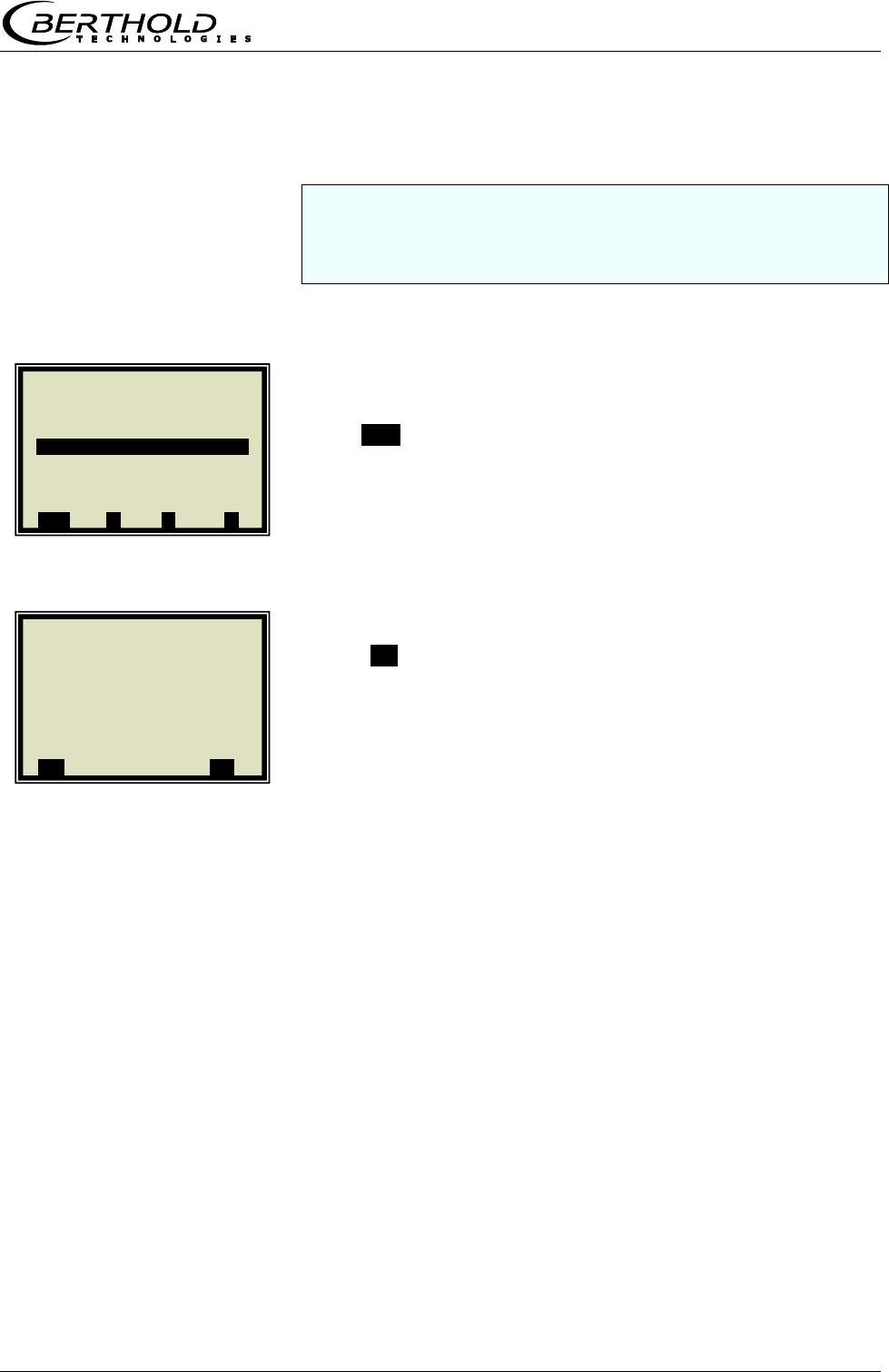
Chapter 5 Calibration
MicroPolar Moist LB 568 55
5.3 Sampling
Before running a sample measurement you have to enable the
desired compensation input and check the calibration. Only the
measured values of the activated inputs are stored in the
sample table.
If the measuring system is not yet in the measurement
mode, start the measurement now.
Push RUN to start the measuring system.
Push .√. to confirm the safety prompt and the device
switches to the measurement mode.
Watch the behavior of the microwave measurement with
running full and empty belt, especially Sigma and Phi(fm) to
ensure that not too many measurements will be rejected with
empty belt or with maximum belt load.
Check before sampling whether all available compensation
devices (e.g. height sensor, belt weigher) have been
parameterized correctly via the analog inputs. Watch and
check the compensation signals also with running full and
empty belt, for example in the live display.
1 | - | LB 568 | 07.05 – 13:25
Live Display
Diagnostic
Setup
Access level Basic
Language English
RUN ▲ ▼ ►
1 | - | Start / Stop | 07.05 –13:25
Switch operating mode?
..X.. ..√..
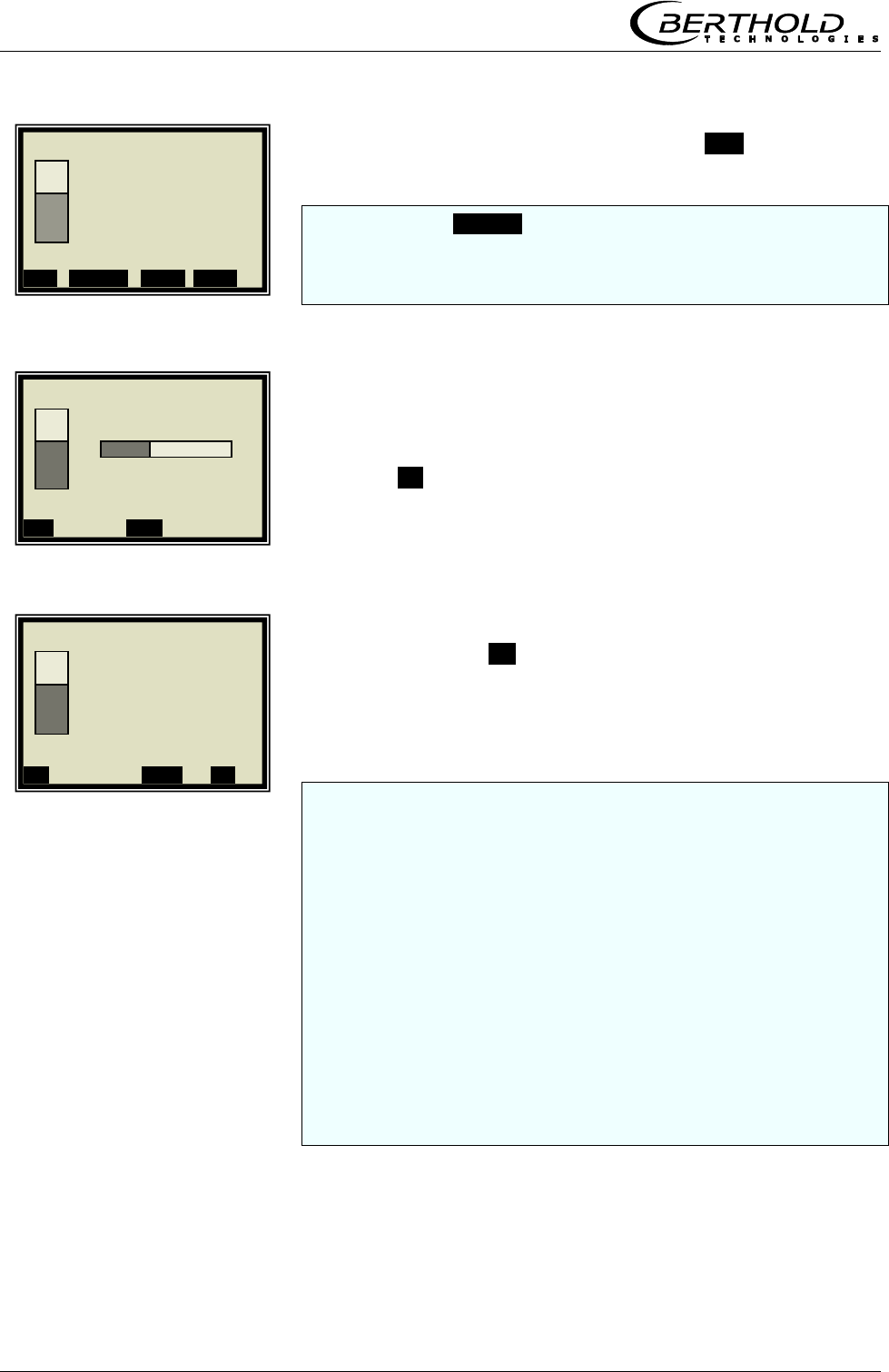
Chapter 5 Calibration
56 MicroPolar Moist LB 568
The display to the left appears if you push RUN.
Note: Push the SAMPLE button to start measurement of the raw
data. At the same time, the laboratory sample has to be taken
and marked. The analysis may be performed later, provided the
product is not changed by this.
Sampling is in process......
Push the .X. button to stop the sampling process any time.
If the sampling process has been completed without any
problem, push the .√. button to save the sample in the table
and the measurement continues.
You have to repeat the process described above for each further
sample.
The moisture/concentration of the samples should be distributed
over the entire measuring range. In case of additional
temperature compensation, the temperature of the samples
should be distributed over the entire temperature range.
The minimum number of samples required is dependent on the
selected calibration modes. If the number of samples is too low,
an error message is displayed after you have attempted to run a
calibration.
About six samples suffice for a rough calculation of the
calibration coefficients, provided the moisture differs by at least
5%. At least 15 samples are required for a fine calibration.
1 | - | Live Display | 07.05 – 13:25
Concentration av.
65.50 %
Conc. av. Conc. act. . 64.35%
ESC SAMPLE ..▲▼.. ZOOM
1 | - | Live Display | 07.05 – 13:25
Taking Sample #1
Conc av. Conc act 64.35%
..X.. .▲▼.
1 | - | Live Display | 07.05 – 13:25
Save sample
no. 1?
Conc av. Conc act 64.35%
..X.. ..▲▼. ..√..
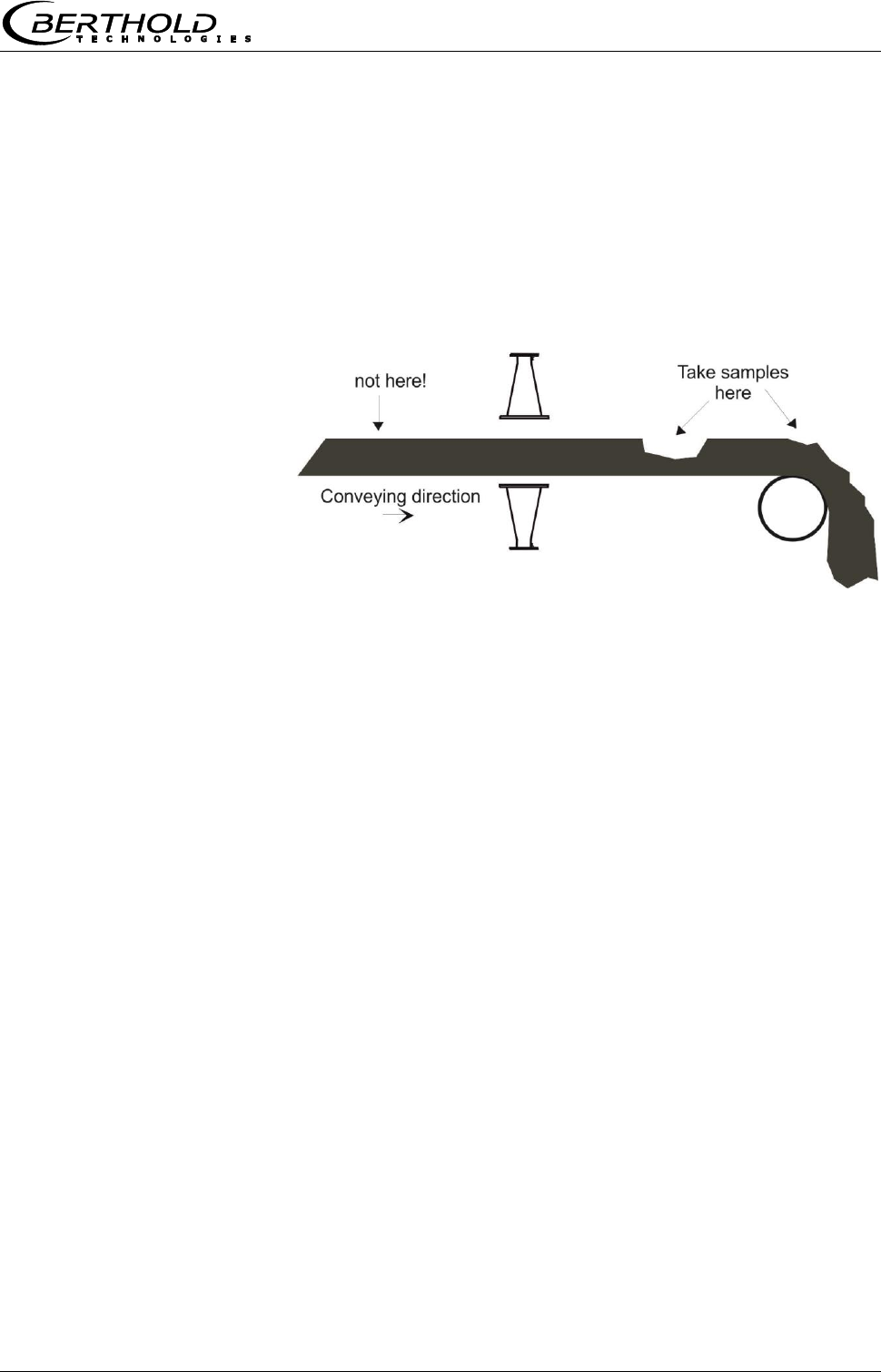
Chapter 5 Calibration
MicroPolar Moist LB 568 57
The moisture/concentration of the samples should be
distributed over the entire measuring range and not vary too
much during each sampling step.
The measuring system has to operate at a normal
throughput and the usual material under actual operating
conditions.
Do not take the samples before the product has passed the
measuring point! The measurement would be disturbed each
time a gap is detected. See the following illustration.
Figure 5-1
Sampling point on the
conveyor belt
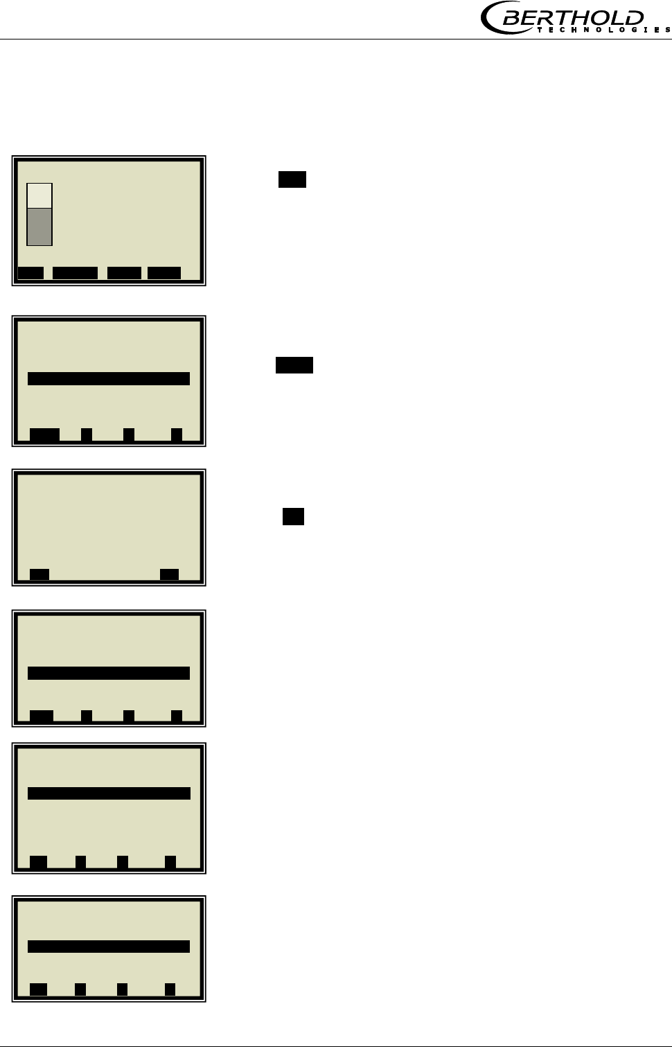
Chapter 5 Calibration
58 MicroPolar Moist LB 568
5.3.1 Entering the Lab Values
Push ESC to go to the main menu. A measurement can be
stopped only on the main menu.
Push STOP to stop the measuring system.
Push .√. to confirm the prompt and the measurement
switches to the STOP mode.
SETUP
CALIBRATION
CALIBRATE CONC
1 | - | Live Display | 07.05 – 13:25
Concentration av.
65.50 %
Conc. av. Conc. act. Act. 64.35%
ESC SAMPLE ..▲▼.. ZOOM
1 | - | LB 568 | 07.05 – 13:25
Live Display
Diagnostic
Setup
Access level Basic
Language English
STOP ▲ ▼ ►
1 | - | Start / Stop | 07.05 –13:25
Switch operating mode?
..X.. ..√..
1 | - | LB 568 | 07.05 – 13:25
Live Display
Diagnostic
Setup
Access level Basic
Language English
RUN ▲ ▼ ►
1 | - | Calibration | 07.05 – 13:25
System adjust
Calibrate conc
⌂◄ ▲ ▼ ►
1 | - | Setup | 07.05 – 13:25
Configuration
Calibration
Input / Output
Product
⌂◄ ▲ ▼ ►
Chapter 5 Calibration
MicroPolar Moist LB 568 59
SAMPLING
LAB VALUE
Delete default value with DEL and enter new value and
confirm with .√..
NEXT SAMPLE
and repeat the step described above with the next sample.
After you have entered the last sample by pushing the ◄
button you get back to the Calibration menu. (Short push – one
page, longer push of the button – you get back to the
Calibration menu immediately)
5.4 Calibration
Proceed as described in chapter 6.4.
1 | - | Calibrate Conc | 07.05 –13:25
Sampling
Tuning
View
⌂◄ ▲ ▼ ►
1 | 1/1 | Sample # 1 | 07.05 –13:25
Next sample
Active Yes
Measured value 65.50%
Lab value 0.00 %
Advanced
.. ◄ . DEL ▲▼ ..√..
1 | 1/1 | Sample # 1 | 07.05 –13:25
Lab Value
0.00| %
ESC ..?.. DEL ..√..
1 | 1/1 | Sample # 1 | 07.05 –13:25
Next sample
Active Yes
Measured value 65.50%
Lab value 72.40 %
Advanced
◄ DEL ▲▼ ..√..
Chapter 6 Calibration and Options
60 MicroPolar Moist LB 568
Chapter 6. Calibration and Options
6.1 Configuration Phi/Att Ratio Plausibility
As described in chapter 3.2.10 Phase Measurement, the
plausibility is determined via Phi Offset for all applications.
Alternatively, the plausibility can also be determined via the
Phi/Att ratio.
From the main menu, you get in the Profi mode to the
display to the left via | SETUP | CONFIGURATION |
PLAUSIBILITY | PHASE MEASURE |
Check and correct your settings using the parameters
displayed to the left.
PHI/ATT RATIO
If you know the ratio value, enter it here; go to chapter 6.1.1
Phi/Att Ratio.
Delete default value with DEL and enter new value and
confirm with .√..
6.1.1 Phi/Att Ratio
If you do not know the ratio value, you have the following
options:
1. Carry out a process recording, see chapter 6.1.2 Process
Recording. Prerequisite for this is that during the
recording the process is moved across the entire
concentration range.
2. If the process recording is currently not possible or if the
concentration range is small anyway (< ± 5%), then
enter Phi/Att = 1 as start value.
Subsequent adjustment of the process recording is possible.
1 | - | Phase measure | 07.05 – 13:25
Phi offset max. 0.00°
Sigma max 500.00
Phi/Att Enabled
Phi/Att ratio 0.00
Auto set OFF
⌂◄ ▲ ▼ ►
1 | - | Phase measure | 07.05 – 13:25
Phi/Att ratio
0.00
ESC ..?.. ▲▼ ..√..
▼ ►
Chapter 6 Calibration and Options
MicroPolar Moist LB 568 61
6.1.2 Process Recording
Prerequisite: You are in the Profi mode and
chapter 4. Configuration
5.1 Scintillation Counter Calibration
5.2 System Adjust
have been completed.
The process recording is used to determine the ratio of Phase
and Attenuation (Phi/Att), a parameter from the plausibility
analysis for correct evaluation of the phase.
If you know the ratio already from other measurements, you
may enter it directly on the PLAUSIBILITY menu (see chapter
3.2.10 Phase Measure); in this case, that process need not
be recorded.
IMPORTANT
The measurement takes place automatically; you only have
to start and stop it again. During measurement, please keep
in mind:
- Do not stop the measurement
- Do not change the concentration erratically (max. 1 %).
- Cover the entire measuring range, if possible
Starting from the main menu, you get in the Profi mode to
the display to the left by selecting
| SETUP | CONFIGURATION | PLAUSIBILITY |
PHASE MEASUREMENT
AUTO SET
1 | - | Plausibility | 07.05 – 13:25
Process limits
Phase measure
⌂◄ ▲ ▼ ►
1 | - |Phase Measure | 07.05 –13:25
Phi offset max. 170.00°
Sigma max. 500.00
Phi/Att Disabled
Phi/Att ratio 0.00
Auto set OFF
⌂◄ ▲ ▼ ►
Chapter 6 Calibration and Options
62 MicroPolar Moist LB 568
ON
Stop logging:
You have the option to stop logging by turning the logging
off. The logging is held and starts again only after it is turned
on again.
Start new logging:
Prerequisite: Logging is turned off. Stop and start the
measurement before you start a new log. The result of older
logs will be deleted.
After recording and turning off the automatic recording you
still have to enable the Plausibility Phi/Att.
Carry out sampling while the process recording is running.
Do not forget to turn off the process recording in the same way
as described above!
1 | - |Phase Measure | 07.05 –13:25
Auto set
Off
On
ESC ..?.. ▲▼ ..√..
1 | - |Phase Measure | 07.05 –13:25
Phi offset max. 170.00°
Sigma max. 500.00
Phi/Att Disabled
Phi/Att ratio 5.32
Auto set ON
⌂◄ ▲ ▼ ►
Chapter 6 Calibration and Options
MicroPolar Moist LB 568 63
6.2 Adjusting the Calibration
A correction factor and an offset may be entered later to
obtain a subsequent adjustment of the calibration (fine
tuning).
Below please find an example for an offset adjustment.
The display to the left appears if you push RUN.
The display reading is now compared with the analysis value
of the lab sample. The difference has to be entered as offset
with the correct algebraic sign.
Calculation:
Analysis value – display = offset Eg. 6-1
Push ESC to go to the main menu.
SETUP
CALIBRATION
CALIBRATE CONC
1 | - | Live Display | 07.05 – 13:25
Concentration av.
65.50 %
Conc. av. Conc. Act. 64.35%
ESC SAMPLE ..▲▼.. ZOOM
1 | - | LB 568 | 07.05 – 13:25
Live Display
Diagnostic
Setup
Access level Basic
Language English
STOP ▲ ▼ ►
1 | - | Setup | 07.05 – 13:25
Configuration
Calibration
Input / Output
Product
⌂◄ ▲ ▼ ►
1 | - | Calibration | 07.05 – 13:25
System adjust
Calibrate conc
⌂◄ ▲ ▼ ►
Chapter 6 Calibration and Options
64 MicroPolar Moist LB 568
TUNING
OFFSET
Calculation formula see chapter 3.2.14 Calibrate
Concentration.
Enter the calculated offset value, confirm with .√. button and
push the Home button ⌂◄ four times to return to the main
menu.
Select
LIVE DISPLAY
to get back to the display.
The reading value should now correspond to the actual value.
1 | - | Calibrate Conc | 07.05 –13:25
Sampling
Tuning
View
⌂◄ ▲ ▼ ►
1 | - | Tuning | 07.05 –13:25
Factor 1.00000
Offset 0.000
⌂◄ ▲ ▼ ►
1 | - | Tuning | 07.05 –13:25
Offset
0.000 |
ESC ..?.. DEL ..√..
1 | - | LB 568 | 07.05 – 13:25
Live Display
Diagnostic
Setup
Access level Basic
Language English
STOP ▲ ▼ ►
1 | - | Live Display | 07.05 – 13:25
Av. av.
75.50 %
Conc. av. Conc. Act. 64.35%
ESC SAMPLE ..▲▼.. ZOOM
Chapter 6 Calibration and Options
MicroPolar Moist LB 568 65
6.3 Output of the Start-up Log
Starting from the main menu, you get in the Profi mode to
the display to the left by selecting | DIAGNOSTIC |
PRINT SETUP
Push .√. button to print the log via RS232. Push .X. to go
back one page without printout.
The start-up log includes all adjustable parameters, data of the
system adjustment, calibration data and entries of the sample
table.
For further information on the start-up log see chapter 9.
Start-up Log.
1 | - | Diagnostic | 07.05 – 13:25
Data log
Error log
Info
Print setup
⌂◄ ▲ ▼ ►
1 | - | Print setup| 07.05 –13:25
Print setup now?
..X.. ..√..
Chapter 6 Calibration and Options
66 MicroPolar Moist LB 568
6.4 Calibration
A variety of setup options exists for calibration. For details
see chapter 3.2.18 Calibration. In addition, the default
settings are displayed, which are usually the best choice.
Prerequisite: You are in the Profi mode and
chapter 4. Configuration
5.1 Scintillation Counter Calibration
5.2 System Adjust
5.3 Sampling
have been completed.
6.4.1 Calibration with One Concentration
Starting from the main menu, you get in the Profi mode to
the display to the left by selecting
| SETUP | CALIBRATION | CALIBRATE CONC |
CALIBRATION
CAL ORDER
LINEAR
Standard for all applications: Linear
Quadratic calibration is possible only for a calibration with three
and more samples.
1 | - | Calibrate Conc | 07.05 –13:25
Sampling
Calibration
Tuning
View
⌂◄ ▲ ▼ ►
1 | - | Calibration | 07.05 – 13:25
Cal. order Linear
Cal. base Attenuation
Coefficients
Start calibr.
⌂◄ ▲ ▼ ►
1 | - | Calibration | 07.05 – 13:25
Cal. order
Linear
Quadratic
⌂◄ ▲ ▼ ►
Chapter 6 Calibration and Options
MicroPolar Moist LB 568 67
CAL. BASE
PHASE (Phase measurement)
Standard for conveyor belt applications: Attenuation
Standard for chute applications: Phase
The calibration base is selected depending on the number of
samples and their raw data. Initial calibration should be as
simple as possible, since calibration can be optimized any time.
START CALIBRATION
Push .√. to start the calibration; push .X. to go back one
page without calibration.
.OK. takes over the calibration and changes to the next
display.
When calculating the new coefficients, the factor will be reset
to 1 and the offset to 0.
1 | - | Calibration | 07.05 – 13:25
Cal. order Linear
Cal. base Attenuation
Coefficients
Start calibr.
⌂◄ ▲ ▼ ►
1 | - | Calibration | 07.05 – 13:25
Cal. base
Phase
Attenuation
Both
⌂◄ ▲ ▼ ►
1 | - | Calibration | 07.05 – 13:25
Cal. order Linear
Cal. base PHI
Coefficients
Start Calibr.
⌂◄ ▲ ▼ ►
1 | - | Calibration | 07.05 – 13:25
Calibrate Now?
..X.. ..√..
1 | - | Calibration | 07.05 – 13:25
Calibrated!
..OK..
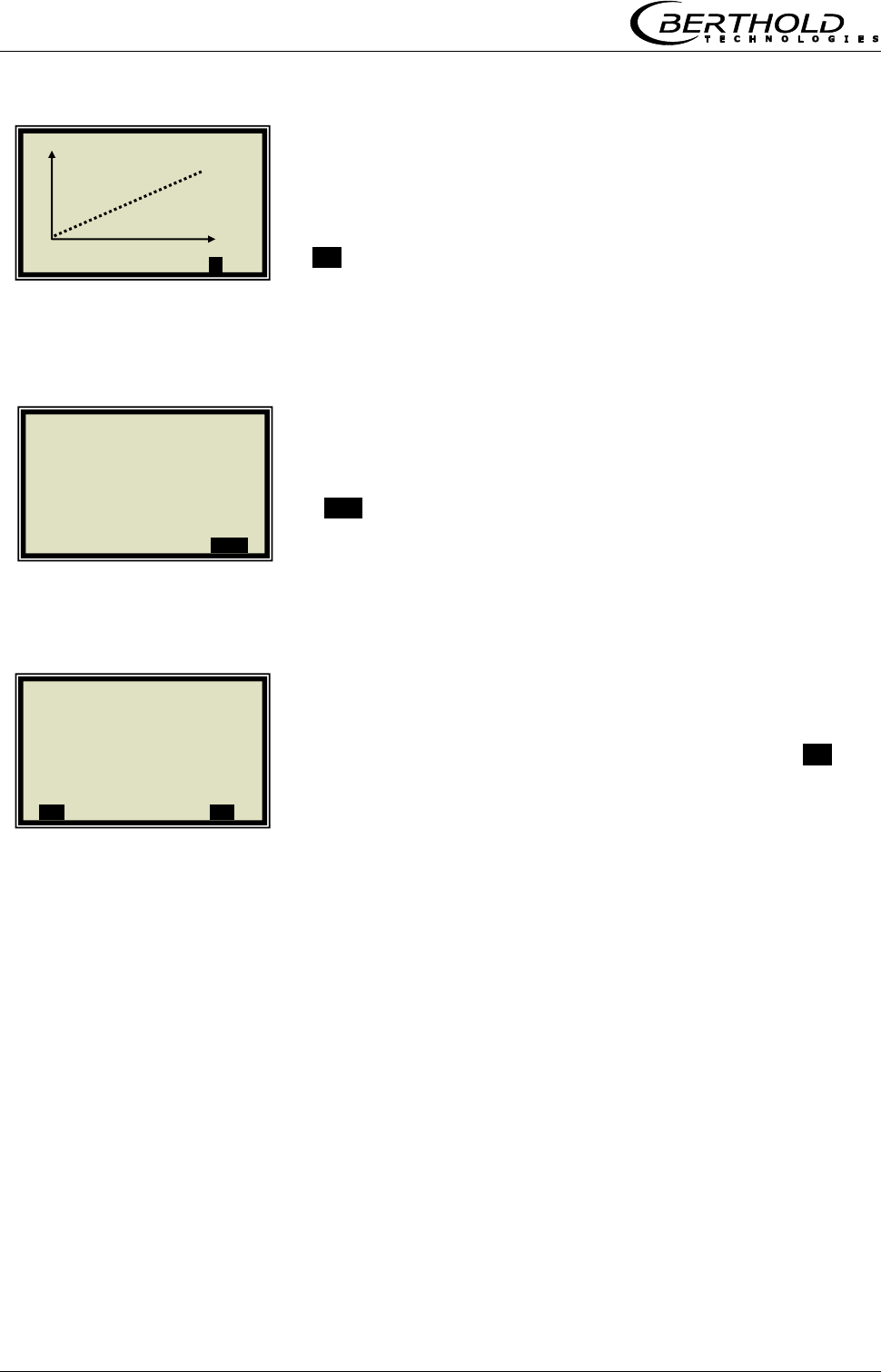
Chapter 6 Calibration and Options
68 MicroPolar Moist LB 568
The curve to the left shows the characteristic curve lab vs.
measured value.
.►.
The correlation indicates the average deviation of the
characteristic curve from the sample series.
.OK.
Upon confirmation, the calibration menu appears again; from
there you get back to the main menu by pushing ⌂◄ four
times and the measurement can be started again.
1 | - | Calibration | 07.05 – 13:25
Lab
►
1 | - | Calibration | 07.05 – 13:25
Correlation Lab/Meas value
0.998726
..OK..
1 | - | Calibration | 07.05 – 13:25
Calibration
OK?
..X.. ..√..

Chapter 6 Calibration and Options
MicroPolar Moist LB 568 69
6.4.2 Calibration with Temperature Compensation
The temperature compensation in general not used for bulk
applications.
Starting from the main menu, you get in the Profi mode to
the display to the left by selecting:
| SETUP | CALIBRATION | CALIBRATE CONC |
CALIBRATION
TEMP. COMP.
INPUT
All active inputs are shown here for compensation selection. The
desired input must already have been active during the sampling
so that the input values in the sample table will be available for
the further calibration.
PT100
The PT100 is selected as an example.
1 | - | Calibrate Conc | 07.05 –13:25
Sampling
Calibration
Tuning
View
⌂◄ ▲ ▼ ►
1 | - | Calibration | 07.05 – 13:25
Cal. order Linear
Cal. base Attenuation
Coefficients
Temp. comp.
Loading comp.
Start Calibr.
⌂◄ ▲ ▼ ►
1 | - | Calibrate Conc | 07.05 –13:25
Input
None
Current In 1
Current In 2
PT100
⌂◄ ▲ ▼ ►
1 | - | Temp. Comp. 1 | 07.05 –13:25
Input None
Mode Additive
Order Linear
Reference value 0.00°C
C_Phi 10.00000
C_dB 10.00000
ESC ..?.. ▲▼ ..√..
Chapter 6 Calibration and Options
70 MicroPolar Moist LB 568
The display to the left shows the default values for the mode
and the order.
Standard for all applications: Mode Additive
Order Linear
You can select additive or multiplicative mode and set the
order to linear or quadratic.
REF. TEMP
The product temperature for the system calibration or the
average operating temperature is entered and confirmed as
reference value.
The coefficients, for example, C_Phi 1 and C_dB 1 are
automatically calculated during calibration
ESC
Now enter the additional settings and calculate the
calibration, as described in chapter 6.4.1 Calibration with one
Concentration.
1 | - | Temp. Comp. 1 | 07.05 –13:25
Reference value.
0.00 | °C
ESC ..?.. DEL ..√..
1 | - | Temp. Comp. 1 | 07.05 –13:25
Input PT100
Mode Additive
Order Linear
Reference value 0.00°C
C_Phi 1 0.00000
C_dB 1 0.00000
ESC ..?.. ▲▼ ..√..
1 | - | Temp. Comp. 1 | 07.05 –13:25
Input PT100
Mode Additive
Order Linear
Reference value 80.00°C
C_Phi 1 0.00000
C_dB 1 0.00000
ESC ..?.. ▲▼ ..√..
1 | - | Temp. Comp. 1 | 07.05 –13:25
Input PT100
Mode Additive
Order Linear
Reference value 0.00°C
C_Phi 1 0.00000
C_dB 1 0.00000
ESC ..?.. ▲▼ ..√..
Chapter 6 Calibration and Options
MicroPolar Moist LB 568 71
6.4.3 Calibration with Load Compensation
Usually the measuring system MicroPolar Moist LB 568 is
operated with the radiometric mass per unit area
compensation. In this case, perform the calibration as
described below.
Starting from the main menu, you get in the Profi mode to
the display to the left by selecting
| SETUP | CALIBRATION | CALIBRATE CONC |
CALIBRATION
LOAD COMP.
The required inputs must be enabled!
COMP. MODE
RADIOM. MPUA
After selection, the LOADING LIMIT is displayed on the
menu.
LOADING LIMIT
1 | - | Calibrate Conc | 07.05 –13:25
Sampling
Calibration
Tuning
View
⌂◄ ▲ ▼ ►
1 | - | Calibration | 07.05 –13:25
Cal. order Linear
Cal. base Attenuation
Temp. comp.
Load comp.
Start Calibr.
⌂◄ ▲ ▼ ►
1 | - |Load Comp | 07.05 –13:25
Comp.Mode disabled
⌂◄ ▲ ▼ ►
1 | - | Load Comp. |07.0 –13:25
Comp. Mode
Disabled
Radiom. MPUA
Load (Current In 1)
Tonnage & Speed
Mass & Height
⌂◄ ▲ ▼ ►
1 | - | Load Comp. | 07.05 –13:25
Comp.Mode Radiom. Mpua
Loading limit
⌂◄ ▲ ▼ ►

Chapter 6 Calibration and Options
72 MicroPolar Moist LB 568
MIN. LOADING
Enter minimum mass per unit area.
Push √ to confirm and three times ⌂◄ to go back.
Now enter the additional settings and calculate the
calibration, as described in chapter 6.4.1 Calibration with one
Concentration.
1 | - |Loading Limit|07.05 –13:25
Min. loading 0.01
⌂◄ ▲ ▼ ►
1 | - |Loading Limit|07.05 –13:25
Min. loading [ ]
0.01
[-10 , 100000]
ESC ..?.. ▲▼ ..√..
Chapter 6 Calibration and Options
MicroPolar Moist LB 568 73
6.4.4 Calibration with Two Concentrations
Calibration for two concentrations starts with changing the
process type as described below.
Starting from the main menu, you get in the Profi mode to
the display to the left by selecting
| SETUP | CALIBRATION |
PROFI
PROCESS TYPE
2 CONC
Push the .√. button to accept the selected process type and
push the ⌂◄ button once to go to the display depicted below.
CALIBRATE CONC (corresponding to concentration 1)
SAMPLING
1 | - |Calibrate Conc1|07.05 –13:25
Sampling
Calibration
Tuning
View
⌂◄ ▲ ▼ ►
1 | - | Calibration | 07.05 – 13:25
System adjust
Calibrate Conc
Calibrate Conc 2
Advanced
⌂◄ ▲ ▼ ►
1 | - | Calibration | 07.05 – 13:25
System ADJUST
Calibrate Conc
Advanced
⌂◄ ▲ ▼ ►
1 | - | Advanced | 07.05 – 13:25
Tare values
Num. cal. sweeps 20
Process type
Extended cal. mode disabled
⌂◄ ▲ ▼ ►
1 | - | Advanced | 07.05 – 13:25
Process type
1 Conc
2 Conc
Split conc
ESC ..?.. ▲▼ ..√..
Chapter 6 Calibration and Options
74 MicroPolar Moist LB 568
For both calibration there is only one sample table.
The lab values have to be entered for all samples used for
calibration of concentration 1. All other samples have to be
disabled (Active.... Yes/No).
LAB VALUE
Delete default value with DEL and enter new value and
confirm with .√..
NEXT SAMPLE
Continue with the next sample.
ACTIVE
Disable sample
NO
1 | 1/4 | Sample # 1 | 07.05 – 13:25
Lab value
60.40 | %
ESC ..?.. DEL ..√..
1 | 1/4 | Sample # 1 | 07.05 –13:25
Next sample
Active Yes
Measured value 65.50%
Lab value 0.00 %
Advanced
◄ DEL ▲▼ ..√..
1 | 1/4 | Sample # 1 | 07.05 –13:25
Next sample
Active Yes
Measured value 65.50 %
Lab value 60.40 %
Advanced
◄ DEL ▲▼ ..√..
1 | 2/4 | Sample # 2 | 07.05 –13:25
Next sample
Active Yes
Measured value 74.35 %
Lab value 67.80 %
Advanced
◄ DEL ▲▼ ..√..
1 | 2/4 | Sample # 2 | 07.05 – 13:25
Enabled
No
Yes
ESC ..?.. DEL ..√..
Chapter 6 Calibration and Options
MicroPolar Moist LB 568 75
Make sure that all samples have been processed and only those
samples are active which are relevant for this calibration.
Push ◄ to get to the Calibration page.
START CALIBRATION
Push .√. to start the calibration; push .X. to go back one
page without calibration.
.OK. takes over the calibration and changes to the next
display.
1 | 2/4 | Sample # 2 | 07.05 –13:25
Next sample
Active No
Measured value 74.35 %
Lab value 67.80 %
Advanced
◄ DEL ▲▼ ..√..
1 | - |Calibrate Conc1|07.05 –13:25
Sampling
Calibration
Tuning
View
⌂◄ ▲ ▼ ►
1 | - | Calibration | 07.05 – 13:25
Calibrate Now?
..X.. ..√..
1 | - | Calibration 1 | 07.05 –13:25
Calibrated!
..OK..
1 | - | Calibration | 07.05 – 13:25
Cal. order Linear
Cal. base Attenuation
Coefficients
Start Calibr.
⌂◄ ▲ ▼ ►
Chapter 6 Calibration and Options
76 MicroPolar Moist LB 568
Push ⌂◄ twice to return two pages.
CALIBRATE CONC 2
Repeat the steps as described above for concentration 2; all
samples have to be enabled again in the sample table. Now you
have to disable all samples which are not used for concentration
2.
SAMPLING
1 | - | Calibration | 07.05 – 13:25
Cal. order Linear
Cal. base Attenuation
Coefficients
Start Calibr.
⌂◄ ▲ ▼ ►
1 | - | Calibration | 07.05 – 13:25
System adjust
Calibrate conc
Calibrate conc 2
Advanced
⌂◄ ▲ ▼ ►
1 | - |Calibrate Conc2|07.05 –13:25
Sampling
Calibration
Tuning
View
⌂◄ ▲ ▼ ►
Chapter 6 Calibration and Options
MicroPolar Moist LB 568 77
6.4.5 Calibration with Split Value
With this type of calibration, two characteristic curves
(concentrations) are combined in one measuring range; their
point of intersection defines the split value.
Conc 1 for the lower and conc 2 for the upper measuring
range can be output only together via current output.
ADVANCED
PROCESS TYPE
SPLIT CONC
Push the .√. button to accept the selected process type and
push the ⌂◄ button once to go to the display depicted below.
The displayed split value has been set by the manufacturer,
but has to be adapted to the respective application.
The sample measurement should be selected such that the last
sample of the lower concentration is fairly close to the first
sample measurement of the upper concentration. Ideally, the
last sample of the initial concentration is the first sample of the
final concentration.
1 | - | Calibration | 07.05 – 13:25
System adjust
Calibrate conc
Advanced
⌂◄ ▲ ▼ ►
1 | - | Advanced | 07.05 – 13:25
Tare values
Num. cal. sweeps 20
Process type
Extended cal. Mode Disabled
⌂◄ ▲ ▼ ►
1 | - | Advanced | 07.05 –
13:25
Process type
1 Conc
2 Conc
Split conc
ESC ..?.. ▲▼ ..√..
1 | - | Advanced | 07.05 – 13:25
Tare values
Num. cal. sweeps 20
Process type Split conc
Split value 75.00 %
Extended cal. Mode Disabled
⌂◄ ▲ ▼ ►
Chapter 6 Calibration and Options
78 MicroPolar Moist LB 568
The sample measurement is carried out continuously over the
entire measuring range with the display depicted to the left. See
chapter 5.3 Sampling.
After completion of sampling, the individual samples will be
enabled or disabled during input of the laboratory values,
relative to the set split values. All samples smaller or equal
to the split value will be assigned to the lower concentration
range and all samples above to the upper concentration
range.
The allocation of the samples takes place automatically, for
example, after the split value has been set or the lab values
have been entered (e.g. after new sampling). The allocation
depends on the split value and the lab value.
IMPORTANT
The split value entry allows you to enable samples that have
been disabled earlier through automatic assignment! In these
cases, disabled samples should better be deleted or disabled
again after a split value entry!
The split value to be set must correspond to the point of
intersection of both calibration curves. This will be corrected
automatically after the calibration (within certain limits).
SPLIT VALUE
Enter the split value and confirm with .√. .
Push ⌂◄ to get to the Calibration page.
1 | - | Live Display | 07.05 – 13:25
Concentration av.
65.50 %
Conc. av. Conc. Act. 64.35%
ESC SAMPLE ..▲▼.. ZOOM
1 | - | Advanced | 07.05 – 13:25
Tare values
Num. cal. sweeps 20
Process type Split conc
Split value 75.00 %
Extended cal. mode disabled
⌂◄ ▲ ▼ ►
1 | - | Advanced | 07.05 – 13:25
Split value
75.00 | %
ESC ..?.. DEL ..√..

Chapter 6 Calibration and Options
MicroPolar Moist LB 568 79
CALIBRATE CONC
CALIBRATION
The lower concentration is now calibrated. Then select
CONC2 and repeat the calibration process.
Back to the main menu and start the measurement.
1 | - | Calibration | 07.05 – 13:25
System adjust
Calibrate conc
Calibrate conc 2
Advanced
⌂◄ ▲ ▼ ►
1 | - |Calibrate Conc2|07.05 –13:25
Sampling
Calibration
Tuning
View
⌂◄ ▲ ▼ ►
Chapter 6 Calibration and Options
80 MicroPolar Moist LB 568
6.4.6 Extended Calibration Mode
It is possible to select an extended calibration mode that
replaces all other calibration calculations including
temperature and loading compensation. Calibration is
performed using the following formula:
Measured value = A1∙Phase + B1∙Attenuation + C
+ D∙PT100 + E∙Input1 +F∙Input2
+ G∙Radiom. Mpua Eg. 6-2
where:
Measured value Concentration / Moisture / Dry mass
A1 Phase coefficient
B1 Attenuation coefficient
C Offset
D Compensation coefficient for PT100 input
E Compensation coefficient for current input 1
F Compensation coefficient for current input 2
G Compensation coefficient for radiom. Mpua
The coefficients can be calculated manually or automatically
from the entries in the sample table.
Upon delivery of this device, this calibration mode is disabled
(default setting). Activation is carried out on the PROFI
menu:
Starting from the main display, you get to the display
depicted to the left via | SETUP | CALIBRATION |
ADVANCED
EXTENDED CAL. MODE
ENABLE
Confirm selection with .√. .
1 | - | Advanced | 07.05 – 13:25
Tare values
Num. cal. sweeps 20
Process type 1 Conc.
Extended cal. mode disabled
⌂◄ ▲ ▼ ►
1 | - | Calibration | 07.05 – 13:25
System adjust
Calibrate conc
Advanced
⌂◄ ▲ ▼ ►
1 | - | Advanced | 07.05 – 13:25
Extended cal. mode
Disabled
Enabled
ESC ..?.. ▲▼ ..√..
Chapter 6 Calibration and Options
MicroPolar Moist LB 568 81
The Setup and Calculation of the calibration is carried out
on the following menu:
Starting from the main menu, you get to the display to the
left by selecting
| SETUP | CALIBRATION | CALIBRATE CONC |
CALIBRATION
Comp input:
Here you can select the analog inputs (PT100, current
input 1 and 2) that are needed for compensation. The
following parameters can be set:
None
Mpua
Mpua + Input 1
Mpua + Input 2
Mpua + PT00
Mpua + Input 1 + Input 2
Mpua + Input 1 + PT100
Mpua + Input 2 + PT100
Mpua + Input 1 + Input 2 + PT100
Input 1
Input 1 + Input 2
Input 1 + PT100
Input 1 + Input 2 + PT100
Input 2
Input 2 + PT100
PT100
Cal. base
The following parameters can be set:
Phase
Attenuation
Both (phase and attenuation)
Coefficients:
On this display, you can edit all calibration coefficients.
Start Calibr.
Starts the calibration using the parameters you have set
earlier.
1 | - | Calibration | 07.05 – 13:25
Comp input. None
Cal. base PHI
Coefficients
Start Calibr.
⌂◄ ▲ ▼ ►
1 | - | Calibrate Conc | 07.05 –13:25
Sampling
Calibration
Tuning
View
⌂◄ ▲ ▼ ►

Chapter 6 Calibration and Options
82 MicroPolar Moist LB 568
6.5 Typical Calibration Coefficients/Start Values
For applications on the conveyor belt and in the measuring
chute it holds:
For dry mass measurement, A1 and B1 must be negative.
Without loading compensation:
]cm/g[ 2
Mpua
1
1A
or Eg. 6-3
]cm/g[ 2
Mpua
6
1B
Eg. 6-4
C: Concentration/moisture value during system calibration
The Mpua can be calculated from Eq. 3-1 in the Hardware
Manual, chapter 3.3 Load Compensation.
With loading compensation using the mass per unit
area:
A1 = 1 or B1 = 6 for moisture measurement
C: Concentration/moisture value during system calibration
With loading compensation using current input 1:
Example of compensation signals:
- Mass flow, for example via a belt weigher
- Material thickness, e.g. via distance measurement
]cm/g[ 2
Mpua
)1In Current(load alminNo
1A
or Eg. 6-5
]cm/g[ 2
Mpua
)1In Current( load alminNo
61B
Eg. 6-6
C: Concentration/moisture value during system calibration
The Mpua can be calculated from Eq. 3-1 in the Hardware
Manual, chapter 3.3 Load Compensation.

Chapter 7 Password
MicroPolar Moist LB 568 83
Chapter 7. Password
The measuring system can be protected against unauthorized
access by passwords.
The access levels are as follows:
Read only
The measuring system cannot be started and stopped. You
can only switch from the live display to Diagnostic and to
Access Level.
Basic
On the Basic level you can make essential entries, and stop
and start the system.
Profi
The Profi mode allows additional entries in the Process type
menu, Calibration menu and opens the Service menu.
Service
The service level is reserved to service personnel.
You have to enter a password to change from the access
level "Read only" to "Basic" or "Profi".
At the time of delivery, this password is
PASS1
The password can be changed in the Profi mode on the menu
| SETUP | CHANGE PASSWORD |.
Changing from Profi to Basic or vice versa is possible without
password.
TIP
Depending on the access level, some menu items are hidden.

Chapter 7 Password
84 MicroPolar Moist LB 568
7.1 Password Forgotten
The device is in the "Read only" mode and the user has
forgotten the password. Please proceed as follows to carry
out a "Reset" of the user level:
Turn off device.
Turn on device; as soon as all 5 LED’s light up after power
on, press 0 (zero) and keep it depressed for 8 seconds.
Device powers up in the "Basic mode". You can now enter a
new password (in the Profi mode).
IMPORTANT
Review your process before you turn off the device. The
current outputs drop to 0 mA.

Chapter 8 Error Lists and Device States
MicroPolar Moist LB 568 85
Chapter 8. Error Lists and Device States
The LED's indicate the device state. After the error has been
remedied, the LED’s are reset to the normal status.
8.1 Hardware Error and Warning Messages
Code
Error
Possible cause
14
Battery voltage
Battery is nearly empty, replace
immediately
See Hardware Manual chapter 5.4
20
HF temperature
out of range
Check the operating temperature
of the evaluation unit, permissible
range
-20 to 45 °C
21
Warning!
Ambient
temperature too
high!
Check the operating temperature
of the evaluation unit, permissible
range
-20 to 45 °C
32
Parameter
memory
incorrect
Compatibility check after software
download: A general reset has to
be performed.
39
HF hardware
error
Troubled cable connection
between motherboard and HF
module. Check connector on the
motherboard.
Warning! First, disconnect the
evaluation unit from the power
supply!
94
No radiometric
detector
connected
No communication between
scintillation counter and evaluation
unit: broken cable, wiring faulty or
not connected.
For all other error messages, please contact the Berthold
Technologies service department.

Chapter 8 Error Lists and Device States
86 MicroPolar Moist LB 568
8.2 Input Error
Error
Probable cause
Value too large
Input value too large
Value too
small
Input value too small
Table is empty
Sample table has been selected without
previous sampling
Chart data
faulty
The measuring system has determined
faulty chart data during calibration.
No chart data
available
The calculated chart data have been deleted
or calibration has not been completed.
Sample table
full
You have tried to measure more than 20
samples.
8.3 Measurement Error and Error Messages
Code
Error
Possible cause
50
Sigma of phase is
too large
The measured phase exceeds
the permissible limit value.
52
Attenuation too
high
The measured attenuation
exceeds the permissible max.
value.
54
No system
calibration done
The system calibration has not
yet been carried out.
56
Phase Offset too
large
The measured phase exceeds
the permissible limit value of
Phase Offset
60
Current input 1 out
of range
The enabled current input has
not yet been calibrated or is not
used.
61
Current input 2 out
of range
The enabled current input has
not yet been calibrated or is not
used.
62
PT100 temperature
out of range
The enabled PT100 input has
not yet been calibrated or is not
used.
70
Concentration out
of range
The concentration lies outside
the process limits.
71
Concentration 2
out of range
The concentration lies outside
the process limits.

Chapter 8 Error Lists and Device States
MicroPolar Moist LB 568 87
Code
Error
Possible cause
72
Loading value 1 smaller
than minimum load
Minimum load not reached,
with respect to
concentration 1.
73
Loading value 2 smaller
than minimum load
Minimum load not reached,
with respect to
concentration 2.
74
Load comp. disabled.
Current input upper
and lower limit invalid
The current input has
exceeded the upper or
lower limit.
75
Synchronization time
too long
Review settings for
synchronization, see
chapter 7.3 in the
Hardware Manual.
76
Synchronization: Speed
out of range
Review settings for
synchronization, see
chapter 7.3 in the
Hardware Manual.
77
Wait for synchronous
value
The measurement has not
yet been synchronized,
please wait.
90
Current input 1 out of
range
The concentration
calculated on the basis of
the current lies outside the
current range.
91
Current input 2 out of
range
The concentration
calculated on the basis of
the current lies outside the
current range.
95
Radiometric detector:
current count rate
> max. count rate
Max. count rate entered
incorrectly or material
loading too low
96
Radiometric detector:
current count rate
< min. count rate
Wrong input, material
loading too high or source -
detector not aligned.
104
Decay compensation:
Device turned off more
than 30 days.
Check date/time
Check and correct the date
and time.
105
Decay compensation
failed:
Enter date/time
Check and correct the date
and time.
For all other error messages, please contact the Berthold
Technologies service.
After the error has been eliminated, the measurement returns to
the status before the error has occurred. An acknowledgment is
not required.

Chapter 8 Error Lists and Device States
88 MicroPolar Moist LB 568
8.4 Device States
Error state:
This condition is indicated by the error codes 50 to 56, 60 to
62 and 70 to 73 (see table above). The evaluation unit shows
the following behavior:
LED’s: RUN flashing, ERROR on, signal 1 and
2, depending on configuration.
Current outputs: Error Current
Display: Error message with error code
Warning state:
This condition is indicated by the error codes 14, 21, 90 and
91 (see table above). The evaluation unit shows the following
behavior:
LED’s: RUN flashing, ERROR off, signal 1 and
2, no correlation.
Current outputs: live
Display: Error message with error code
Hold state:
Measurement was stopped via digital input. The evaluation
unit shows the following behavior:
The mean concentration value is frozen. The measurement
continues, however, so that a measurement fault may trigger
the error condition also in the Hold state.
LED’s: RUN flashing, ERROR off, signal 1 and
2 depending on configuration.
Current outputs: frozen
Display: No display message

Chapter 9 Start-up Log
MicroPolar Moist LB 568 89
Chapter 9. Start-up Log
The log can be output via RS232. The output takes place in
menu | DIAGNOSITIC | PRINT SETUP |.
The serial interface RS232 has the following connection
settings:
Data transfer rate 38400 baud, 8 data bits, no parity, 1 stop
bit
The log is stored to a TXT file using a terminal program. For
the presentation (e.g. in Excel®), the following data format
has to be taken into account.
Separator: Tabulator
Decimal separator: .
Thousand separator ,
The following code list helps you to interpret the start-up log,
see example of a log in chapter 9.1.
Parameters
Code
Information
Log type
0
1
2
3
Log type:
Disabled
Single
Continuous
Stop at error
Log time
0
1
2
3
4
5
Log time:
15 minutes
1 hour
4 hours
8 hours
1 day
3 days
Measuring
mode
0
1
Measuring mode:
Continuous
Batch
Start mode
0
1
Start mode (Start/Stop):
Keyboard
External
Wave band
selection
0
1
2
3
Frequency band selection:
Full range
Standard
Resonance scan
Specific

Chapter 9 Start-up Log
90 MicroPolar Moist LB 568
Parameters
Code
Information
Extended
calibration
mode
0
1
Extended Cal mode:
Off
On
Extended
calibration
input
selection
0
1
2
3
4
5
6
7
8
9
10
11
12
13
14
15
Extended Cal input selection:
None
Mpua
Mpua + Input 1
Mpua + Input 2
Mpua + PT00
Mpua + Input 1 + Input 2
Mpua + Input 1 + PT100
Mpua + Input 2 + PT100
Mpua + Input 1 + Input 2 + PT100
Input 1
Input 1 + Input 2
Input 1 + PT100
Input 1 + Input 2 + PT100
Input 2
Input 2 + PT100
PT100
Calibration
mode
0
1
Calibration degree:
Linear regression
Quadratic regression
Calibration
variable
0
1
2
Calibration basis:
Phase
Attenuation
Phase and attenuation
Temp.
compensation
input
0
1
2
3
Temp. compensation input:
None
Current In 1
Current In 2
PT100
Temp.
compensation
mode
0
1
Compensation mode:
Additive
Multiplicative
Temp.
compensation
fit
0
1
Compensation degree:
Linear regression
Quadratic regression
Loading
comp.
selection:
0
1
2
3
4
Selection of loading compensation:
Disabled
Radiom. MPUA
Loading (Cin 1)
Tonnage & Speed
Mass & Height
Synchronizer
mode
0
1
2
Synchronization mode:
Disabled
Const. velocity
Variable velocity
Measure
configuration
0
1
2
Process type:
1 concentration
2 concentrations
Split concentration

Chapter 9 Start-up Log
MicroPolar Moist LB 568 91
Parameters
Code
Information
AO Assign
Code
0
1
2
3
4
5
Assignment current output:
None
Concentration
Concentration 2
Current In 1
Current In 2
PT100
AO Alarm
select code
0
1
2
3
Error current output:
22 mA
3.5 mA
Hold
Value
Range
selection
0
1
Measuring range current output:
0 … 20 mA
4 … 20 mA
Compensation
input
0
1
2
3
Compensation input:
None
Current In 1
Current In 2
Pt100
AI Range
selection
0
1
Measuring range current input:
0 … 20 mA
4 … 20 mA
AI Enabled[2]
Status of current input 2
DO Function
0
1
2
4
5
Function of the digital outputs:
None
Error
Hold
Alarm min.
Alarm max.
DO
Assignment
0
1
2
3
4
Digital output: the min./max. alarm
is assigned as follows:
Concentration
Concentration 2
Current In 1
Current In 2
PT100
DI Function
selection
0
1
2
3
4
Function of the digital inputs:
None
Start/Stop
Hold
Sampling
Product selection
Printout mode
0
1
2
3
Mode of data output:
None
Line
Table
Line + table

Chapter 9 Start-up Log
92 MicroPolar Moist LB 568
Parameters
Code
Information
Access level
0
1
2
3
Access level:
Read only
Basic
Profi
Service
Language
0
1
2
Language selection
English
German
French

Chapter 9 Start-up Log
MicroPolar Moist LB 568 93
9.1 Example Start-up Log
Menu:
Start of Setup:
Start-up Log
Interpretation:
(* only relevant for service)
Product
Entry
Product1
Product2
Prod.3
Prod.4
Datalog
Log type :
1
Log type: see Code list
Log time :
2
Log time: see Code list
Number of errors :
2
Number of entries in the error log
NTC temperature :
45.3 °C
*
max. NTC temperature :
46.7 °C
*
9V power supply :
7.94 V
*
Info
Tag:
-
Tag
Device type:
LB 568
Device type :
Unique device ID number :
4294967295
Serial number :
4294967295
Final assembly number :
000-000
Software version :
V1.00
Software release date :
31.08.2012
Software revision date
Actual date :
01.09.2012
Date of recording
Actual time :
18:03
Time of recording
Measurement
Measuring mode :
0
Measuring mode: see code list
Start mode :
0
Start mode: see code list
Filter damping value :
20
Averaging number
Filter damping value[2] :
20
*
Filter damping value[3] :
20
*
Reset average :
FALSE
Reset averaging: Yes/No
Plausibility
Lower limit :
0
Min. process limit
Upper limit :
100
Max. process limit
Max. phase sigma :
500
Sigma max.
Max. Phase at zero freq.(°)
170.00 °/GHz
Residual phase max.
Correlation Phi/Att :
0
Phase/attenuation ratio
Auto-set mode :
FALSE
Auto set: On/Off
Unwrap algor. EPS value :
500.00 °
*
PhiM jump corr. enable :
TRUE
Phase jump correction, enabled: Yes/No
PhiM jump corr. variance :
150.00 °
Variance for the phase jump correction
PhiM jump corr. filter damp :
4
Averaging number for the phase jump
correction
PhiM jump corr. filter post correction :
FALSE
*
Microwave
Ref. cable length :
4.00 m
Reference cable length
Signal cable length :
4.00 m
Signal cable length
Wave band selection :
1
Frequency band: see code list
Start frequency :
0
*
Internal Attenuation :
0
*
Marker
Marker name :
Mark1
Marker name for concentration
Marker value :
50
Marker value for concentration
Marker name[2] :
Mark2
Marker name for concentration 2
Marker value[2] :
50
Marker value for concentration 2
System
adjust
Nbr of sweeps for reference :
10
Number of sweeps for system
calibration

Chapter 9 Start-up Log
94 MicroPolar Moist LB 568
Calibrate
concen-
tration 2
Extended calibration mode :
0
Extended Cal. mode: see Code list
Extended calibration input selection:
0
Extended Cal input selection: see Code
list
Calibration mode :
0
Calibration degree: see code list
Calibration variable :
1
Calibration basis: see code list
Phase coefficients :
0
Phase coefficient
A1
Phase coefficients[2] :
0
Phase coefficient
A2
Attenuation coefficients :
0
Attenuation
Coefficient
B1
Attenuation coefficients[2] :
0
Atten. coefficient
B2
Constant coefficient :
10
Constant
C
d coefficient
0
Comp. coefficient for PT100 input
e coefficient
0
Comp. coefficient for current input 1
f coefficient
0
Comp. coefficient for current input 2
g coefficient
0
Comp coefficient for mpua
Adjust factor :
1
Factor
Adjust offset :
0
Offset
Temp. compensation mode:
0
Compensation mode: see code list
Temp. compensation input :
0
Compensation input: see code list
Temp. compensation fit:
0
Compensation fit: see code list
Temp. compensation reference :
0
Compensation reference value
Phase coeff. for temp. comp. :
0
Comp. Phase coefficient
K_Ph1
Phase coeff. for temp.comp.[2] :
0
Comp. Phase coefficient
K_Ph2
Attenuation coeff. for temp.comp :
0
Comp. Atten. coefficient
K_dB1
Attenuation coeff. for temp.comp[2]
0
Comp. Atten. coefficient
K_dB2
Loading comp. selection :
0
Loading comp. selection: see code list
Loading comp. lower limit :
0.01
Minimum load
Synchronizer mode :
0
Synchronizer mode: see code list
Current input1 distance to uWave :
0
Distance to the microwave measuring
path
Current input2 distance to uWave :
0
Distance to the microwave measuring
path
Radiometry distance to uWave :
0
Distance for the radiometric measuring
path
Plausibility
for
concen-
tration 2
Lower limit :
0
Min. process limit
Upper limit :
100
Max. process limit

Chapter 9 Start-up Log
MicroPolar Moist LB 568 95
Calibrate
concen-
tration 2
Calibration mode :
0
Calibration degree: see code list
Calibration variable :
1
Calibration basis: see code list
Phase coefficients :
0
Phase coefficient
A1
Phase coefficients[2] :
0
Phase coefficient
A2
Attenuation coefficients :
0
Atten. coefficient
B1
Attenuation coefficients[2] :
0
Atten. coefficient
B2
Constant coefficient :
10
Constant
C
d coefficient
0
Comp. coefficient for PT100 input
e coefficient
0
Comp. coefficient for current input 1
f coefficient
0
Comp. coefficient for current input 2
g coefficient
0
Comp coefficient for mpua
Adjust factor :
1
Factor
Adjust offset :
0
Offset
Temp. compensation mode:
0
Compensation mode: see code list
Temp. compensation input :
0
Compensation input: see code list
Temp. compensation fit :
0
Compensation degree: see code list
Temp. compensation reference :
0
Compensation reference value
Phase coeff. for temp. comp. :
0
Comp. Phase coefficient
K_Ph1
Phase coeff. for temp.comp.[2] :
0
Comp. Phase coefficient
K_Ph2
Attenuation coeff. for temp.comp :
0
Comp. Atten. coefficient
K_dB1
Attenuation coeff. for temp.comp[2]
0
Comp. Atten. coefficient
K_dB2
Loading comp. selection :
0
Loading comp. selection: see code list
Loading comp. lower limit :
0.01
Minimum load
Advanced
Tare Phase (°/GHz) :
0.00 °/GHz
Tare Attenuation (dB) :
0.00 dB
Measure configuration :
0
Process type: see code list
Range split value :
75
Split value
Current
output 1
AO Assign code :
1
Assignment: see code list
AO Upper range value :
100.00%
Upper value
AO Lower range value :
0.00%
Lower limit
AO Current value :
4.00 mA
Actual current
AO Alarm select code :
2
Error current: see code list
AO Error current value :
22.00 mA
Error current value
Current
output 2
AO Assign code[2] :
0
Assignment: see code list
AO Upper range value[2] :
100
Upper value
AO Lower range value[2] :
0
Lower limit
Range selection[2] :
1
Range
AO Current value[2] :
4.00 mA
Actual current
AO Alarm select code[2] :
2
Error current: see code list
AO Error current value[2] :
22.00 mA
Error current value
Current
input 1
AI Enabled :
0
Disabled: 0
Enabled: 1
AI Range selection :
1
Range: see code list
AI Upper range value :
100
Upper value
AI Lower range value :
0
Lower limit
AI Current :
0.00 mA
Live current
Current
input 2
AI Enabled[2] :
0
Disabled: 0
Enabled: 1
AI Range selection[2] :
1
Range: see code list
AI Upper range value[2] :
100
Upper value
AI Lower range value[2] :
0
Lower limit
AI Current[2] :
0.02 mA
Live current

Chapter 9 Start-up Log
96 MicroPolar Moist LB 568
PT100
input
AI Enabled[3] :
0
Disabled: 0
Enabled: 1
PT100 value :
2.8 °C
PT100 live value
Relay 1
DO Function :
1
Function: see code list
DO Assignment :
0
Assignment: see code list
DO Threshold :
0.00%
*
DO Hysteresis :
5.00%
*
Relay 2
DO Function[2] :
2
Function: see code list
DO Assignment[2] :
0
Assignment: see code list
DO Threshold[2] :
0.00%
*
DO Hysteresis[2] :
5.00%
*
Digital
inputs
DI Function selection :
0
Function digital input 1: see code list
DI Function selection[2] :
0
Function digital input 2: see code list
DI Function selection[3] :
0
Function digital input 3: see code list
Printout mode :
1
Data output: see code list
Access level :
2
Access level: see code list
Language :
1
Language: see code list
Radiom.
detector
Radiometric detector measurement
state:
0
Disabled 0
Enabled: 1
Cps filter damp :
10
Averaging of the count rate
Cps validation mode :
1
Disabled 0
Enabled: 1
CPS max value :
100000 cps
Maximum count rate
CPS min value :
0 cps
Min. count rate
HV control mode :
0
Automatic: 0
Manual: 1
Actual HV :
450.0 V
Current high voltage
Detector software version :
1.2.4
Detector software version
Detector unique id :
1161953277
Detector device ID no.
Mass per unit area transducer
state:
0
0 = no radiom. compensation enabled
1 = radiom. compensation enabled
Absorption coefficient for MPUA
calculation :
0.07
Absorption coefficient for MPUA
calculation,
MPUA = Mass per unit area
Ray angle of radiation source :
0°
Radiation angle
Io rate :
0 cps
Zero count rate
Selected nuclide at I null
determination :
0
0 = Cs137
1 =Am241
Io max. time :
180 s
Max. recording time for Io
Reference measurement done (Io) :
FALSE
Reference measurement done: Yes/No
Nuclide selection :
0
0 = Cs137
1 =Am241
End of Setup
End

Chapter 9 Start-up Log
MicroPolar Moist LB 568 97
Start of Reference Data
System adjustment data:
Product 1:
Mean Atten.:
46.8509 dB
Phase at fm:
42.6285 deg/GHz
Phase offset:
-825.586 deg
Phase slope:
380,984 deg/GHz
Phase correlation:
0.998212
Phase sigma:
0.24575
Frequency[GHz]
Phase[Deg]
Transformed
Phase[Deg]
Atten.[dB]
3.101
35.64
35.64
21.98
3.131
361.81
361.81
21.95
3.161
689.04
689.04
22.07
3.191
1014.44
1014.44
22.36
3.221
1339.01
1339.01
22.37
3.251
1664.16
1664.16
22.68
3.281
1989.9
1989.9
22.32
3.311
2319.19
2319.19
22.57
3.341
2642.87
2642.87
22.46
3.371
2972.88
2972.88
22.42
3.401
3296.79
3296.79
22.83
3.431
3623.71
3623.71
22.43
3.461
3949.32
3949.32
22.51
3.491
4275.35
4275.35
22.34
3.521
4601.84
4601.84
22.27
3.551
4929.07
4929.07
22.44
3.581
5254.83
5254.83
22.45
3.611
5582.38
5582.38
22.47
3.641
5907.4
5907.4
22.67
3.671
6230.12
6230.12
22.77
3.701
6489.69
6489.69
22.24
3.731
6755.95
6755.95
22.23
3.761
6922.09
6922.09
22.24
3.791
7387.71
7387.71
22.25
3.821
7854.85
7854.85
22.02
3.851
7854.85
7854.55
22.89
3.881
7387.71
7387.71
22.41
Start of Sample Data:
Sampling:
Product 1: Sample Data for Concentration 1:
Sample: Active:
Con .(%):
Lab.(%):
AIN1:
AIN2:
Temp.
(°C):
Phi.
(°/GHz):
Att.(dB):
Mqua
(g/cm2):
1|17.03 - 12:37 TRUE
40
40
0
0
0
-0.35
0.02
0.00
2|17.03 - 12:37 TRUE
35
35
0
0
0
30.33
5.08
0.00
3|17.03 - 12:45 TRUE
25
25
0
0
0
59.02
18.98
0.00
Correlation factor between
lab and meas values:
1
End of Sample Data
Do not use following data!