Bewator 5PQ-SM500 Contactless Smartcard Reader User Manual
Bewator Ltd. Contactless Smartcard Reader Users Manual
UserManual.wiki
>
Bewator
>
5PQ-SM500 User Manual
>
Users Manual
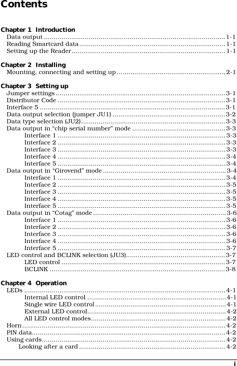
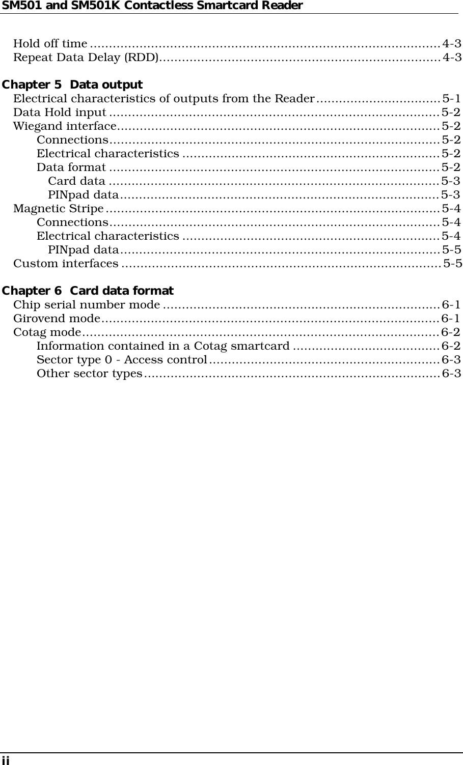
Contents
1.
Installation Manual
2.
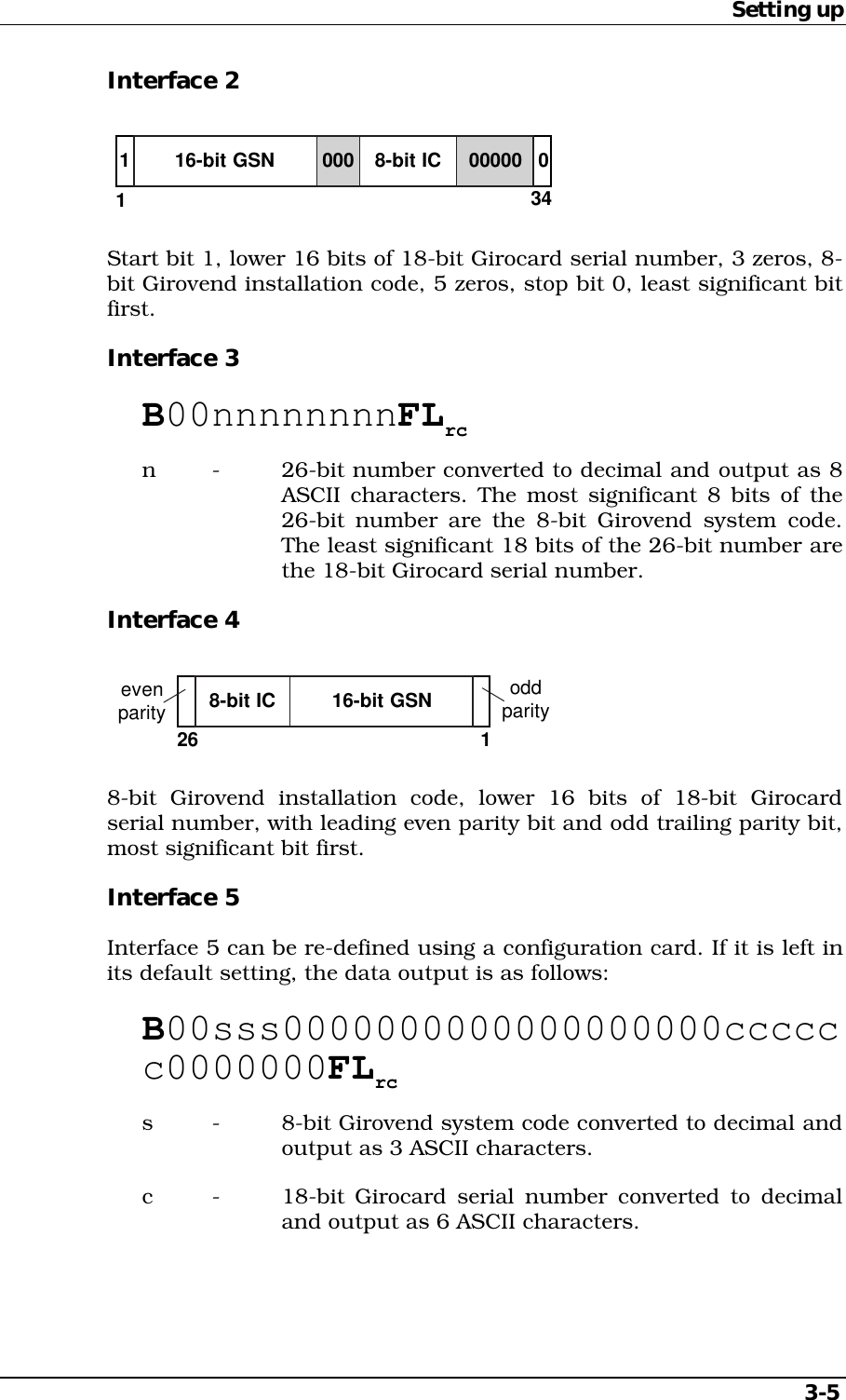
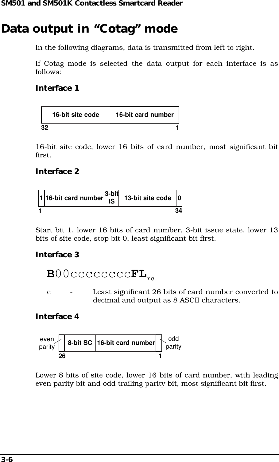
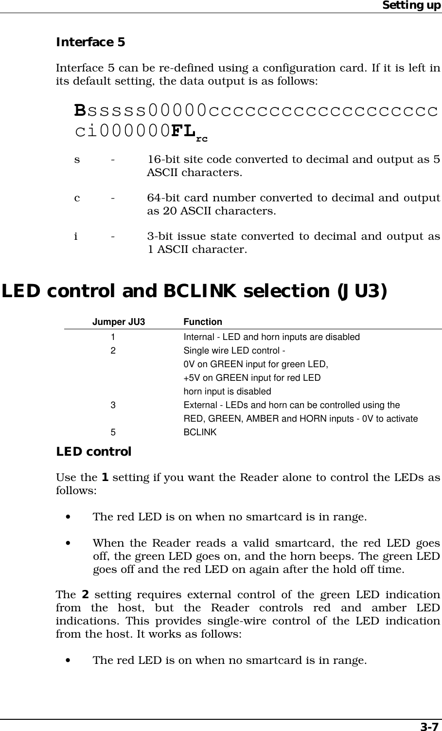
Users Manual
Users Manual
Navigation menu
Upload a User Manual
Namespaces
Wiki Guide
HTML
PDF
Info
Views
User Manual
Discussion / Help
Navigation