Bewator 5PQ-SM500 Contactless Smartcard Reader User Manual
Bewator Ltd. Contactless Smartcard Reader Users Manual
Bewator >
Contents
- 1. Installation Manual
- 2. Users Manual
Users Manual
SM501 and SM501K
Contactless Smartcard
Reader Handbook
HB02/104 Iss 1A
Applicability
This handbook applies to the SM501 and SM501K Contactless
Smartcard Readers
© BEWATOR COTAG JANUARY 2000
This handbook is based on the best information available to Bewator Cotag at the time of publication.
Although every effort is made to keep our documentation up to date, small changes which arise from
the Company's policy of continuing product improvement are not necessarily incorporated. Some
products are not available in all countries. All orders are accepted only on the Company's standard
Conditions of Sale, copies of which are available on request.
Bewator Cotag, a division of Bewator Group Ltd, Mercers Row, Cambridge CB5 8EX, UK
Tel: +44 (0)1223 321535 Fax: +44 (0)1223 366799 Email: sales@bewator-cotag.com www.bewator-cotag.com


i
Contents
Chapter 1 Introduction
Data output .............................................................................................1-1
Reading Smartcard data...........................................................................1-1
Setting up the Reader...............................................................................1-1
Chapter 2 Installing
Mounting, connecting and setting up........................................................2-1
Chapter 3 Setting up
Jumper settings.......................................................................................3-1
Distributor Code ......................................................................................3-1
Interface 5 ...............................................................................................3-1
Data output selection (jumper JU1) ..........................................................3-2
Data type selection (JU2)..........................................................................3-3
Data output in “chip serial number” mode ................................................3-3
Interface 1 ......................................................................................3-3
Interface 2 ......................................................................................3-3
Interface 3 ......................................................................................3-3
Interface 4 ......................................................................................3-4
Interface 5 ......................................................................................3-4
Data output in “Girovend” mode...............................................................3-4
Interface 1 ......................................................................................3-4
Interface 2 ......................................................................................3-5
Interface 3 ......................................................................................3-5
Interface 4 ......................................................................................3-5
Interface 5 ......................................................................................3-5
Data output in “Cotag” mode....................................................................3-6
Interface 1 ......................................................................................3-6
Interface 2 ......................................................................................3-6
Interface 3 ......................................................................................3-6
Interface 4 ......................................................................................3-6
Interface 5 ......................................................................................3-7
LED control and BCLINK selection (JU3)...................................................3-7
LED control ....................................................................................3-7
BCLINK ..........................................................................................3-8
Chapter 4 Operation
LEDs .......................................................................................................4-1
Internal LED control .......................................................................4-1
Single wire LED control...................................................................4-1
External LED control.......................................................................4-2
All LED control modes.....................................................................4-2
Horn........................................................................................................4-2
PIN data...................................................................................................4-2
Using cards..............................................................................................4-2
Looking after a card...........................................................................4-2

SM501 and SM501K Contactless Smartcard Reader
ii
Hold off time............................................................................................4-3
Repeat Data Delay (RDD)..........................................................................4-3
Chapter 5 Data output
Electrical characteristics of outputs from the Reader.................................5-1
Data Hold input.......................................................................................5-2
Wiegand interface.....................................................................................5-2
Connections.......................................................................................5-2
Electrical characteristics ....................................................................5-2
Data format .......................................................................................5-2
Card data .......................................................................................5-3
PINpad data....................................................................................5-3
Magnetic Stripe........................................................................................5-4
Connections.......................................................................................5-4
Electrical characteristics ....................................................................5-4
PINpad data....................................................................................5-5
Custom interfaces ....................................................................................5-5
Chapter 6 Card data format
Chip serial number mode .........................................................................6-1
Girovend mode.........................................................................................6-1
Cotag mode..............................................................................................6-2
Information contained in a Cotag smartcard .......................................6-2
Sector type 0 - Access control.............................................................6-3
Other sector types..............................................................................6-3

1-1
Chapter 1
Introduction
The SM501 and SM501K Contactless Smartcard Readers are
designed to read the codes contained in “Mifare” smartcards and to
pass these codes to a host system.
The SM501K has an integrated keypad. As well as reading cards, it
also passes data entered on the keypad to the host system.
The Readers consists of a printed circuit assembly and keypad
mounted inside a plastic enclosure. They require a DC power supply.
Data output
Each Reader provides a choice of Wiegand, Mag Stripe or BCLINK
format data output for the card data (and the PIN data on the K
model).
Reading Smartcard data
By setting a jumper, the Reader can be configured to read one of
three areas of data from the Smartcard:
• Read chip serial number from any Mifare card
• Read Girovend information only from Girovend cards
• Read Cotag information only from Cotag cards
Setting up the Reader
You configure the Reader using jumpers as desribed in chapter 2.

SM501 and SM501K Contactless Smartcard Reader
1-2
2-1
Chapter 2
Installing
Mounting, connecting and setting up
Mount the Reader in a suitable position near the door approximately
1.2m from the floor. The Reader can be installed outside in a
sheltered position.
The Reader has a mounting plate with two oval mounting holes which
are suitable for most installations - you first need to break open the
mounting holes using a screwdriver. There are also four round holes
in the mounting plate which will align with a standard wall box of the
type used, for example, for light switches.
1. If the Reader is fixed to the mounting plate, undo the four
screws which are in each corner, then place the mounting
plate in position on the wall or door frame and mark the
position of the two mounting holes. Note: the mounting plate
must be positioned with its connector at the top left.
2. Drill the two mounting holes. The holes accept 3.5mm machine
screws or No 6 wood screws.
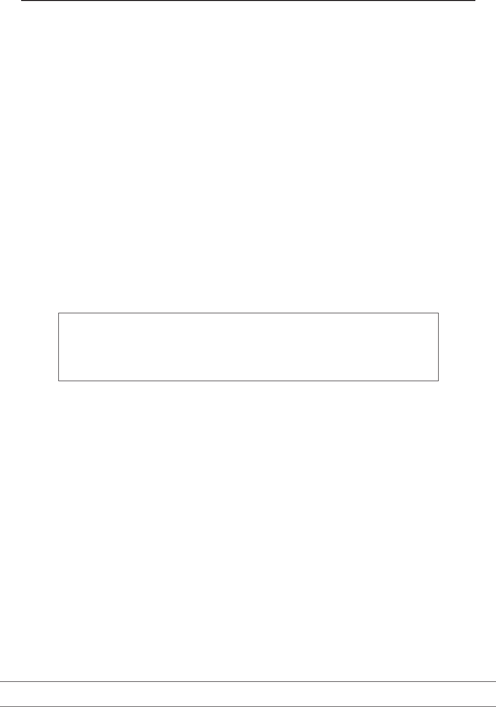
3. The connections are made to the connector on the mounting
plate. Pass the cable through the large hole in the centre of the
mounting plate. Note: the two power supply cables must be
passed twice through the hole in the ferrite bead supplied with
the Reader before they are joined to the connector, as shown in
the following diagram:
-
+
from power supply
each cable passes through ferrite bead twice
0V
V+ to connector on mounting plate
4. Make the connections shown in the following table as required:
Name Function
V+ Power supply +V (+ve) unregulated DC
max 36.0V, min 10.0V, 250mA max
0V Power supply 0V (-ve),
(also ground reference for data output)
Amber Either: Amber LED control - 0V for amber LED
Or: BCLINK data interface Rx
Horn Horn - 0V to sound
Red Either: Red LED control - 0V for red LED
Or: BCLINK data interface address

SM501 and SM501K Contactless Smartcard Reader
2-2
Name Function
Green Either: Green LED control - 0V for green LED
Or: Single wire LED control
0V for green LED, +5V for red LED
(0V also switches off amber LED)
D0 Data zero for Wiegand output
Data for Mag Stripe output
BCLINK data interface Tx
D1 Data one for Wiegand output
Clock for Mag Stripe output
DA Data Available for Wiegand or Mag Stripe output
Note: do not apply a voltage greater than +5V to the horn input
or the LED inputs
4. Route the cable tidily, then screw the mounting plate to the
wall or door frame. Make sure all braid and loose filaments of
wire are cut right back or insulated with tape or sleeving.
5. Set the jumpers on the Reader to provide the functions you
require, as described in the following tables:
INTERFACE
Jumper JU1 Function
1 32 bit Wiegand
2 34 bit Wiegand
3 10 character Mag Stripe
4 26 bit Wiegand
5 37 character Mag Stripe
DATA
Jumper JU2 Function
1 Read chip serial number from any Mifare card
2 Read Girovend information only from Girovend cards
3 Read Cotag information only from Cotag cards
4 not used
5 not used
LED CONTROL
Jumper JU3 Function
1 Internal - LED and horn inputs are disabled
2 Single wire LED control -
0V on GREEN input for green LED,
+5V on GREEN input for red LED
3 External - LEDs and horn can be controlled using the
RED, GREEN, AMBER and HORN inputs - 0V to activate
5 BCLINK
6. Locate the Reader on the mounting plate with the LEDs at the
top left and press it home - the Reader cannot be pushed fully
home unless it is the correct way round.

Installing
2-3
7. Tighten the screws, then insert the little plastic plugs supplied
with the Reader into the screw-holes so that the screws cannot
be seen and the case looks neat. (Note that the plastic plugs
cannot be removed without damaging them - four spare plugs
are supplied with each Reader.)
8. Power up the Reader and test it: hold a smart card close to the
outline of the card engraved on the face of the Reader - the
Reader should bleep when the card is read and the host
should receive the card data output. Each key-press should
give an amber flash and the host should receive PIN data.

SM501 and SM501K Contactless Smartcard Reader
2-4

3-1
Chapter 3
Setting up
Jumper settings
You set the following functions using jumpers on the Reader:
• The protocol used by the Reader for data output (Wiegand,
Mag Stripe or BCLINK)
• The type of data to be read from the Smartcard (chip serial
number, Girovend, Cotag)
• Function of LEDs and horn
Distributor Code
In Girovend and Cotag modes, you can teach the Reader a Distributor
Code. (In Girovend mode the “System Code” is the Distributor Code.)
When you power up the Reader, there is a 4 second configuration
period which is signified by the green LED being lit. If you present a
card within this period, the Reader learns the Distributor Code from
the card and bleeps for 2 seconds. After learning a Distributor Code,
the Reader will ignore all cards with the wrong Distributor Code.
Interface 5
Interface 5 can be re-programmed using a configuration card to give
the data output that you require: contact Technical Support in
Cambridge for details.

SM501 and SM501K Contactless Smartcard Reader
3-2
Data output selection (jumper JU1)
Using jumper JU1, you can choose from three Wiegand and two Mag
Stripe (ABA) data outputs as shown in the table below:
Interface
1
Interface
2
Interface
3
Interface
4
Interface
5*
Interface type
Wiegand
Wiegand
ABA
Wiegand
ABA
Bit length
500
µ
s
500
µ
s
1.5ms
500
µ
s
1.5ms
Pulse width
100
µ
s
100
µ
s
500
µ
s
100
µ
s
500
µ
s
Number of
bits/characters
32
34
10
26
37
Data hold
implemented**
No
No
No
No
No
D0 active high/low
low
low
low
low
low
D1 active high/low
low
low
low
low
low
DA active high/low
low
low
low
low
low
Repeat data delay
2s
2s
2s
2s
2s
Read hold off time***
1s/5s
1s/5s
1s/5s
1s/5s
1s/5s
Following for ABA
formats only :-
Number of leading
zero bits
8
8
Number of trailing
zero bits
8
8
*This interface can be redefined by presenting a Cotag programmed
smartcard during the configuration period - contact Technical
Support in Cambridge for details.
**If Data Hold is implemented, the amber LED will not work.
***The hold off time is 1 second on the SM501 Reader, and is 5
seconds on the SM501K Reader. If a key is pressed within the 5
seconds hold off time on the SM501K Reader, the hold off time is
reset to 2 seconds from the time the key was pressed. Pressing
another key within the 2 seconds hold off time resets the hold off time
again, so that it is always 2 seconds after the last key was pressed.
Note: if JU3 is set to position 5 for BCLINK data output, the position
of JU1 has no effect.
Setting up
3-3
Data type selection (JU2)
Jumper JU2 Function
1 Read chip serial number from any Mifare card
2 Read Girovend information only from Girovend cards
3 Read Cotag information only from Cotag cards
Data output in “chip serial number” mode
In the following diagrams, data is transmitted from left to right.
If chip serial number (CSN) mode is selected the data output for each
interface is as follows:
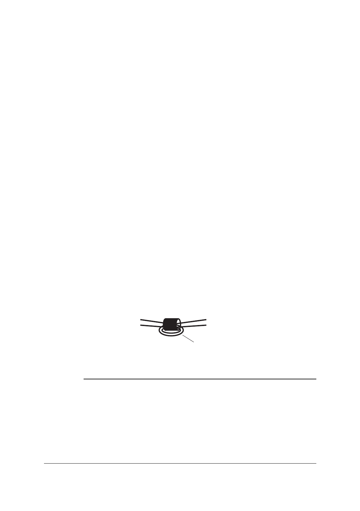
Interface 1
132
32-bit CSN
32-bit chip serial number, most significant bit first.
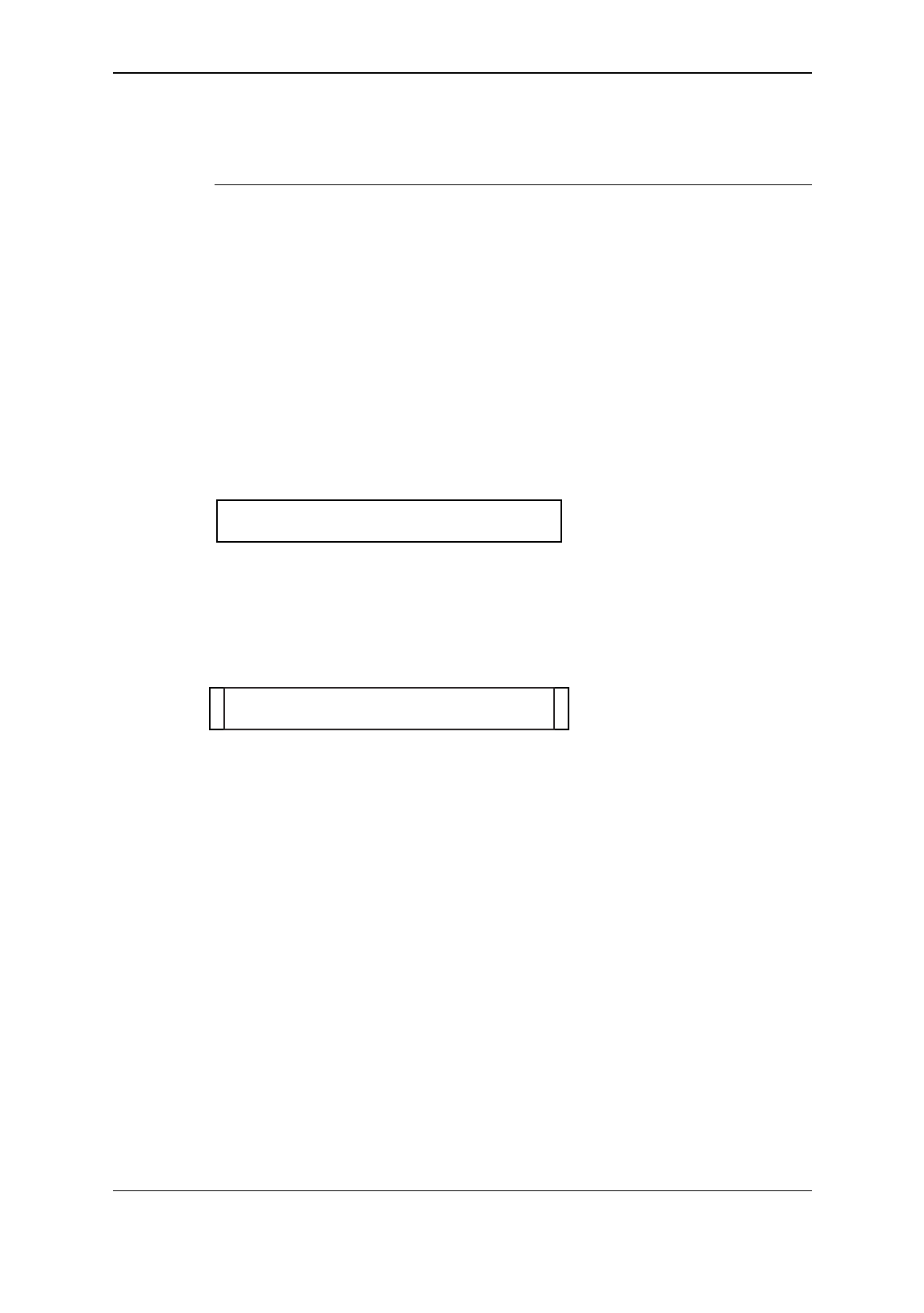
Interface 2
32-bit CSN
134
10
Start bit 1, 32-bit chip serial number, stop bit 0, least significant bit
first.
Interface 3
BccccccccccFLrc
c - 32-bit chip serial number converted to decimal and
output as ten ASCII characters
SM501 and SM501K Contactless Smartcard Reader
3-4
Interface 4
lower 24 bits of CSN
1
odd
parity
even
parity
26
Lower 24 bits of chip serial number with leading even parity bit and
odd trailing parity bit, most significant bit first.
Interface 5
Interface 5 can be re-defined using a configuration card. If it is left in
its default setting, the data output is as follows:
B00000000000000000000ccccccccc
c0000000FLrc
c - 32-bit chip serial number converted to decimal and
output as ten ASCII characters
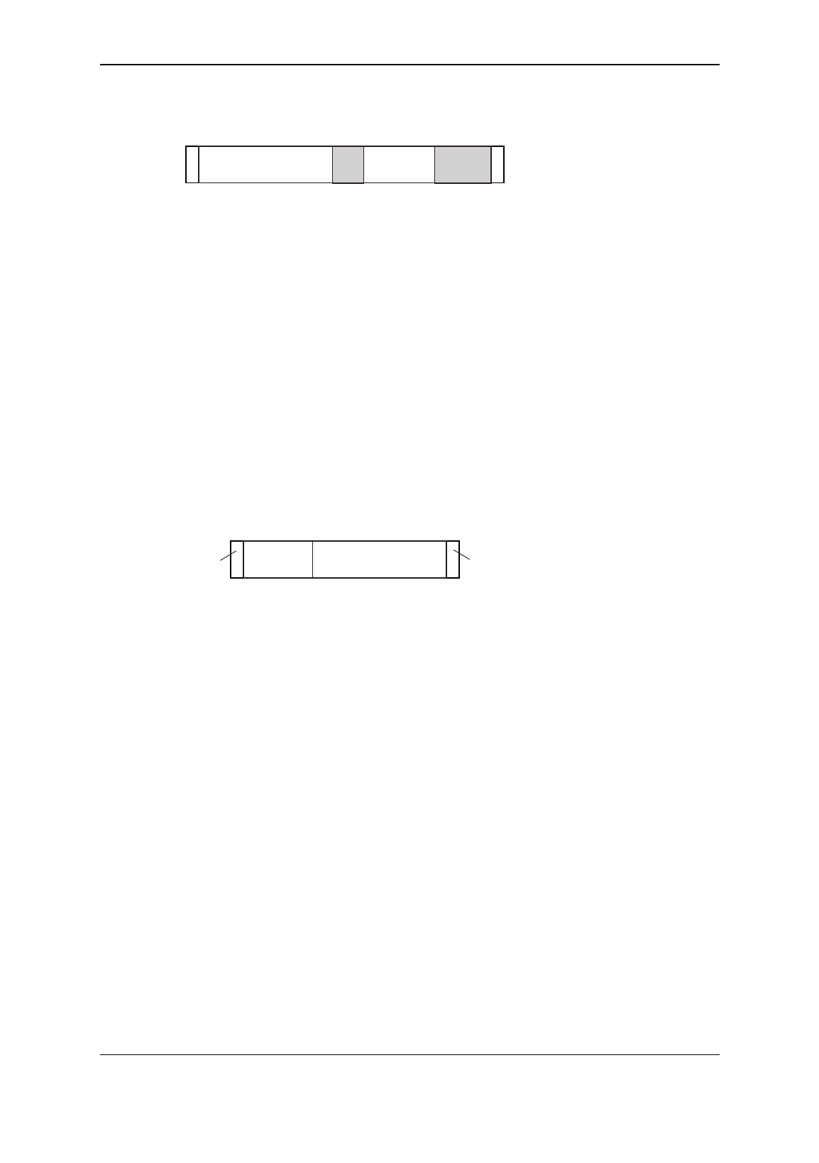
Data output in “Girovend” mode
In the following diagrams, data is transmitted from left to right, and
the shaded areas are zeros.
If Girovend mode is selected the data output for each interface is as
follows:
Interface 1
132
18-bit GSN8-bit IC000000
6 zeros, 8-bit Girovend installation code, 18-bit Girocard serial
number, most significant bit first.
Setting up
3-5
Interface 2
16-bit GSN
134
108-bit IC000 00000
Start bit 1, lower 16 bits of 18-bit Girocard serial number, 3 zeros, 8-
bit Girovend installation code, 5 zeros, stop bit 0, least significant bit
first.
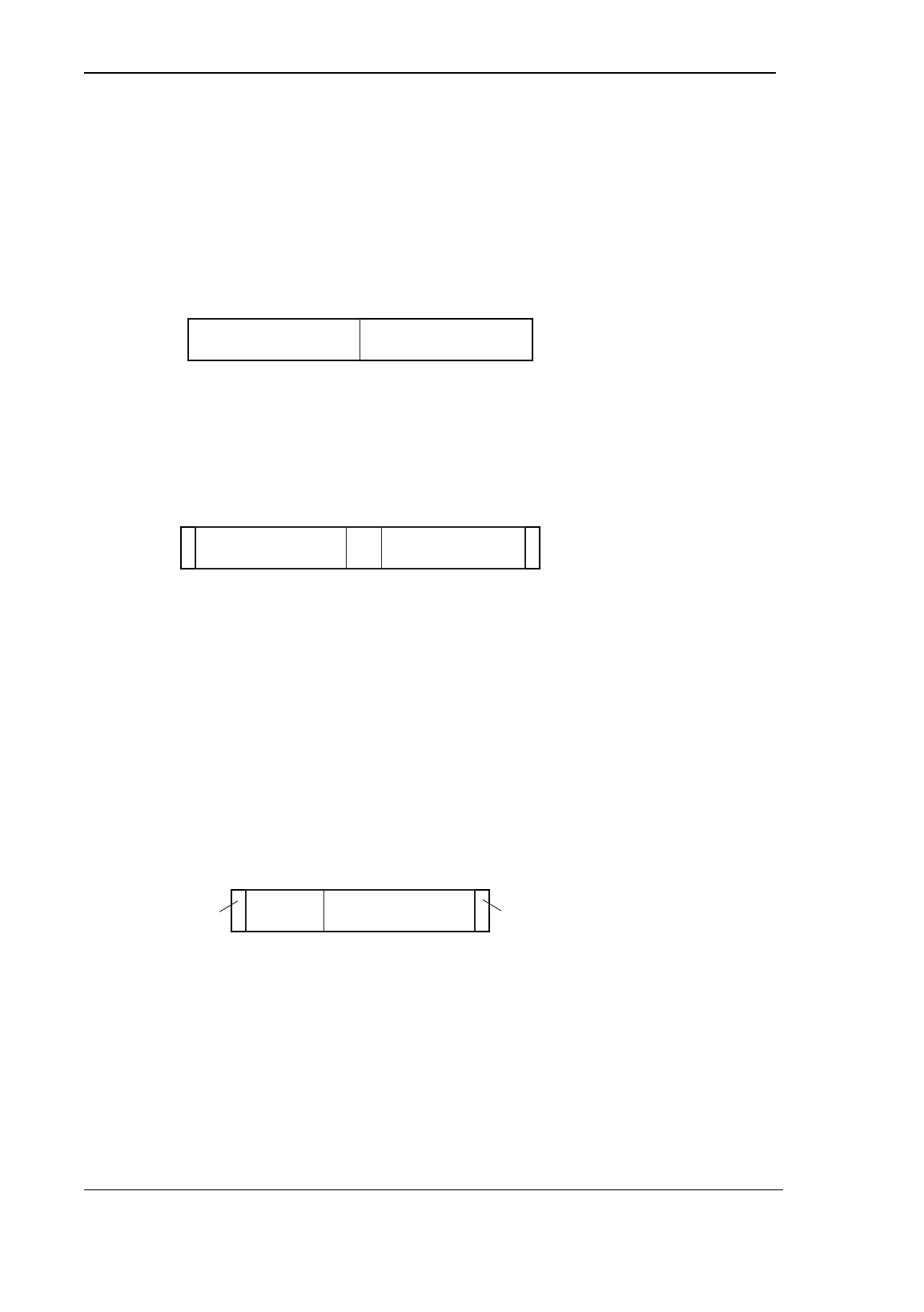
Interface 3
B00nnnnnnnnFLrc
n - 26-bit number converted to decimal and output as 8
ASCII characters. The most significant 8 bits of the
26-bit number are the 8-bit Girovend system code.
The least significant 18 bits of the 26-bit number are
the 18-bit Girocard serial number.
Interface 4
1
odd
parity
16-bit GSN8-bit IC
even
parity
26
8-bit Girovend installation code, lower 16 bits of 18-bit Girocard
serial number, with leading even parity bit and odd trailing parity bit,
most significant bit first.
Interface 5
Interface 5 can be re-defined using a configuration card. If it is left in
its default setting, the data output is as follows:
B00sss0000000000000000000ccccc
c0000000FLrc
s - 8-bit Girovend system code converted to decimal and
output as 3 ASCII characters.
c - 18-bit Girocard serial number converted to decimal
and output as 6 ASCII characters.
SM501 and SM501K Contactless Smartcard Reader
3-6
Data output in “Cotag” mode
In the following diagrams, data is transmitted from left to right.
If Cotag mode is selected the data output for each interface is as
follows:
Interface 1
132
16-bit card number16-bit site code
16-bit site code, lower 16 bits of card number, most significant bit
first.
Interface 2
16-bit card number
134
10
3-bit
IS 13-bit site code
Start bit 1, lower 16 bits of card number, 3-bit issue state, lower 13
bits of site code, stop bit 0, least significant bit first.
Interface 3
B00ccccccccFLrc
c - Least significant 26 bits of card number converted to
decimal and output as 8 ASCII characters.
Interface 4
1
odd
parity
16-bit card number8-bit SC
even
parity
26
Lower 8 bits of site code, lower 16 bits of card number, with leading
even parity bit and odd trailing parity bit, most significant bit first.

Setting up
3-7
Interface 5
Interface 5 can be re-defined using a configuration card. If it is left in
its default setting, the data output is as follows:
Bsssss00000ccccccccccccccccccc
ci000000FLrc
s - 16-bit site code converted to decimal and output as 5
ASCII characters.
c - 64-bit card number converted to decimal and output
as 20 ASCII characters.
i - 3-bit issue state converted to decimal and output as
1 ASCII character.
LED control and BCLINK selection (JU3)
Jumper JU3 Function
1 Internal - LED and horn inputs are disabled
2 Single wire LED control -
0V on GREEN input for green LED,
+5V on GREEN input for red LED
horn input is disabled
3 External - LEDs and horn can be controlled using the
RED, GREEN, AMBER and HORN inputs - 0V to activate
5 BCLINK
LED control
Use the 1 setting if you want the Reader alone to control the LEDs as
follows:
• The red LED is on when no smartcard is in range.
• When the Reader reads a valid smartcard, the red LED goes
off, the green LED goes on, and the horn beeps. The green LED
goes off and the red LED on again after the hold off time.
The 2 setting requires external control of the green LED indication
from the host, but the Reader controls red and amber LED
indications. This provides single-wire control of the LED indication
from the host. It works as follows:
• The red LED is on when no smartcard is in range.

SM501 and SM501K Contactless Smartcard Reader
3-8
• When the Reader reads a valid smartcard, the red LED stays
on and the amber LED comes on. The amber LED remains on
for the period of the hold off time.
• If the GREEN input on the connector is pulled low (0V) while
the amber LED is on, both red and amber LEDs go off and the
green LED comes on, and the hold off time is cancelled.
• The green LED stays on until the GREEN input returns high
(+5V), when the green LED goes off and the red LED comes on
again.
Use the 3 setting when the drives for LED indications and horn are
supplied by the host system. The LEDs follow the inputs labelled
RED, GREEN and AMBER on the connector: +5V for off, 0V for on.
The horn follows the Horn input: +5V for off, 0V for on. Note that,
even when the LEDs and horn are driven externally, the amber LED
will flick for 100ms whenever a key is pressed on the SM501K
Reader, and the horn will beep for 100ms whenever a card is read on
either Reader.
BCLINK
Set JU3 to position 5 if you want to transmit data from the Reader in
BCLINK format. This setting overrides all settings of JU1.

4-1
Chapter 4
Operation
Once you have set up all the options described in chapter 3, “Setting
up”, normal operation simply consists of presenting your card to the
Reader, entering your PIN on the keypad if the Reader is type
SM501K, and awaiting the response. The Readers are always used in
conjunction with a host system which controls the door lock
mechanism (or any other equipment in different applications) and
takes decisions about when to activate it.
LEDs
Internal LED control
Under internal control (LEDs driven by Reader), the indicator LEDs
work as follows:
• The red LED is on when no smartcard is in range.
• When the Reader reads a valid smartcard, the red LED goes
off, the green LED goes on, and the horn beeps. The green LED
goes off and the red LED on again after the hold off time*.
Single wire LED control
Under single wire control (red and amber LEDs driven by Reader,
green LED driven by host), the indicator LEDs work as follows:
• The red LED is on when no smartcard is in range.
• When the Reader reads a valid smartcard, the red LED stays
on and the amber LED comes on. The amber LED remains on
for the period of the hold off time*.
• If the GREEN input on the connector is pulled low (0V) while
the amber LED is on, both red and amber LEDs go off and the
green LED comes on, and the hold off time* is cancelled.
• The green LED stays on until the GREEN input returns high
(+5V), when the green LED goes off and the red LED comes on
again.
*The hold off time depends on which type of Reader you are using;
see the section on the hold off time later in this chapter.

SM501 and SM501K Contactless Smartcard Reader
4-2
External LED control
Under external control (LEDs driven by host), the indicator LEDs
follow the RED, AMBER and GREEN terminals on the connector.
All LED control modes
In all of the above LED control modes, the amber LED flicks on or off
(depending on its current state) for 100ms whenever a key is pressed
on the SM501K Reader.
Horn
The horn bleeps for 100ms whenever the Reader reads a valid
smartcard.
If External LED Control is selected, the horn can be controlled
externally using the Horn terminal on the connector.
PIN data
The SM501K Reader outputs PIN data whenever a key is pressed,
irrespective of whether it has read a card.
Using cards
The Readers are designed for use with a hand-held card. Present the
face of the card near the Reader and wait for the horn to beep.
Looking after a card
• Don’t let the card get too hot - for example if left in a car on a
sunny day. The operating temperature range for the card is
-20 to +50oC.
• Don’t deliberately bend the card and take care not to sit on it
in your pocket.
• To clean the card, use a damp cloth. Don’t use any solvents
and don’t immerse it in anything.

Operation
4-3
Hold off time
When the Reader reads a valid card, it will not read a card again until
the hold off time has elapsed.
The standard data ouputs which are available using jumper JU1 all
give a hold off time of 1 second for the SM501 Reader, and 5 seconds
for the SM501K Reader.
If a key is pressed within the 5 seconds hold off time on the SM501K
Reader, the hold off time is reset to 2 seconds from the time the key
was pressed. Pressing another key within the 2 seconds hold off time
resets the hold off time again, so that it is always 2 seconds after the
last key was pressed.
Repeat Data Delay (RDD)
When the Reader reads data from a card, it sends card data to the
host. After it has done this, it will not send the same card data to the
host again until the RDD time has elapsed. This prevents the system
becoming overloaded with lots of data from one card being read over
and over again.
The standard data ouputs which are available using jumper JU1 all
give a repeat data delay of 2 seconds. Note that if the hold off time is
longer than the RDD (as with the standard data outputs on the
SM501K Reader), the RDD has no effect.

SM501 and SM501K Contactless Smartcard Reader
4-4
5-1
Chapter 5
Data output
The SM501 and SM501K Readers offer a choice of Wiegand or
Magnetic Stripe or BCLINK interface to communicate with a host
system. You select the interface you require using the jumpers on the
Reader, see chapter 3.
Electrical characteristics of outputs from the
Reader
The Wiegand interface uses the data lines D0, D1 and DA.
All outputs are driven by open drain drivers which can each sink up
to 250mA. When a driver is off, its output is pulled up to +5V (the
regulated logic voltage on the board) by a 1k resistor (and also by
whatever is connected at the host end).
The polarities of the three data outputs (D0, D1 and DA) are
individually selectable (active-high or active-low) using a
configuration card: contact Technical Support in Cambridge for
details.
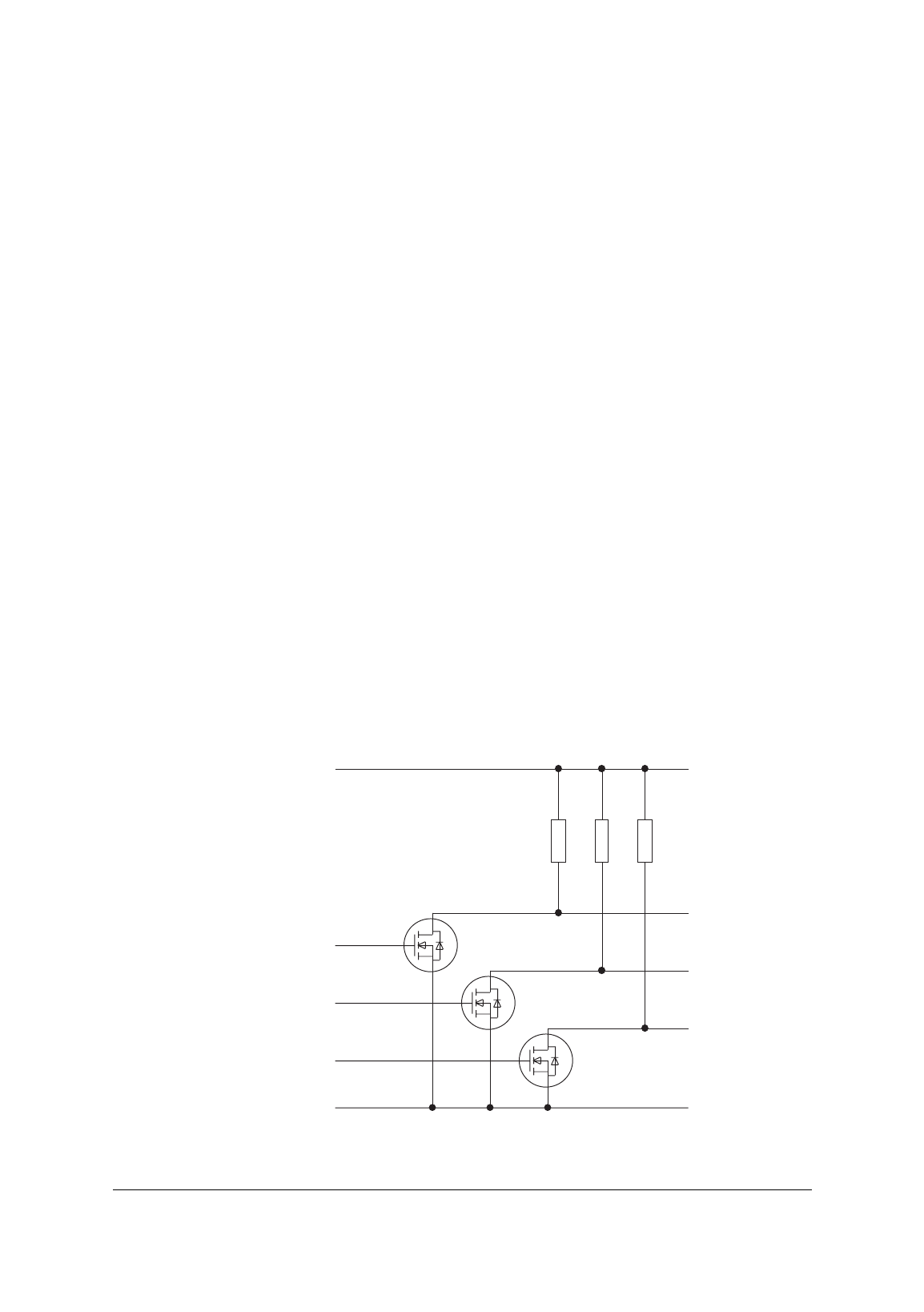
The diagram below shows the logical implementation of the outputs
used for the Wiegand interface.
D0
D1
DA
+5V
0V
0V
1k 1k 1k

SM501 and SM501K Contactless Smartcard Reader
5-2
Data Hold input
The Reader can be configured to use the AMBER LED input as a Data
Hold input (
H
). This can be used by the host to buffer up to five data
message in the Reader until the host is ready to read them. This
enables the data lines from two Readers to be connected in parallel,
the host polling each in turn by releasing its Data Hold input, reading
the data, then asserting the Data Hold input again. If you do not read
the messages quickly enough and the message buffer becomes full,
new messages will be thrown away.
Wiegand interface
Connections
The pin connections for the Wiegand interface are as follows:
0V (ground)
D0 (logic 0)
D1 (logic 1)
DA (data available)
Electrical characteristics
The interface provides three outputs: logic zero data (D0), logic one
data (D1) and data available (DA).
Data transfer is performed by pulsing the D0 line to indicate a logic
zero and by pulsing the D1 line to indicate a logic one. The voltage of
the data lines is +5V or 0V.
The Data Available output (DA) is provided to tell the host system it
must read a data message from the Reader. DA becomes active 1ms
before data is sent and is released 1ms after the data has been sent.
Data format
There are three aspects to the format of the data message, all of
which can be varied, depending on the interface setting you use:
• Framing bits at the start and finish of the message.
• Any parity bits which may be used.
• The data from the card.
Data output
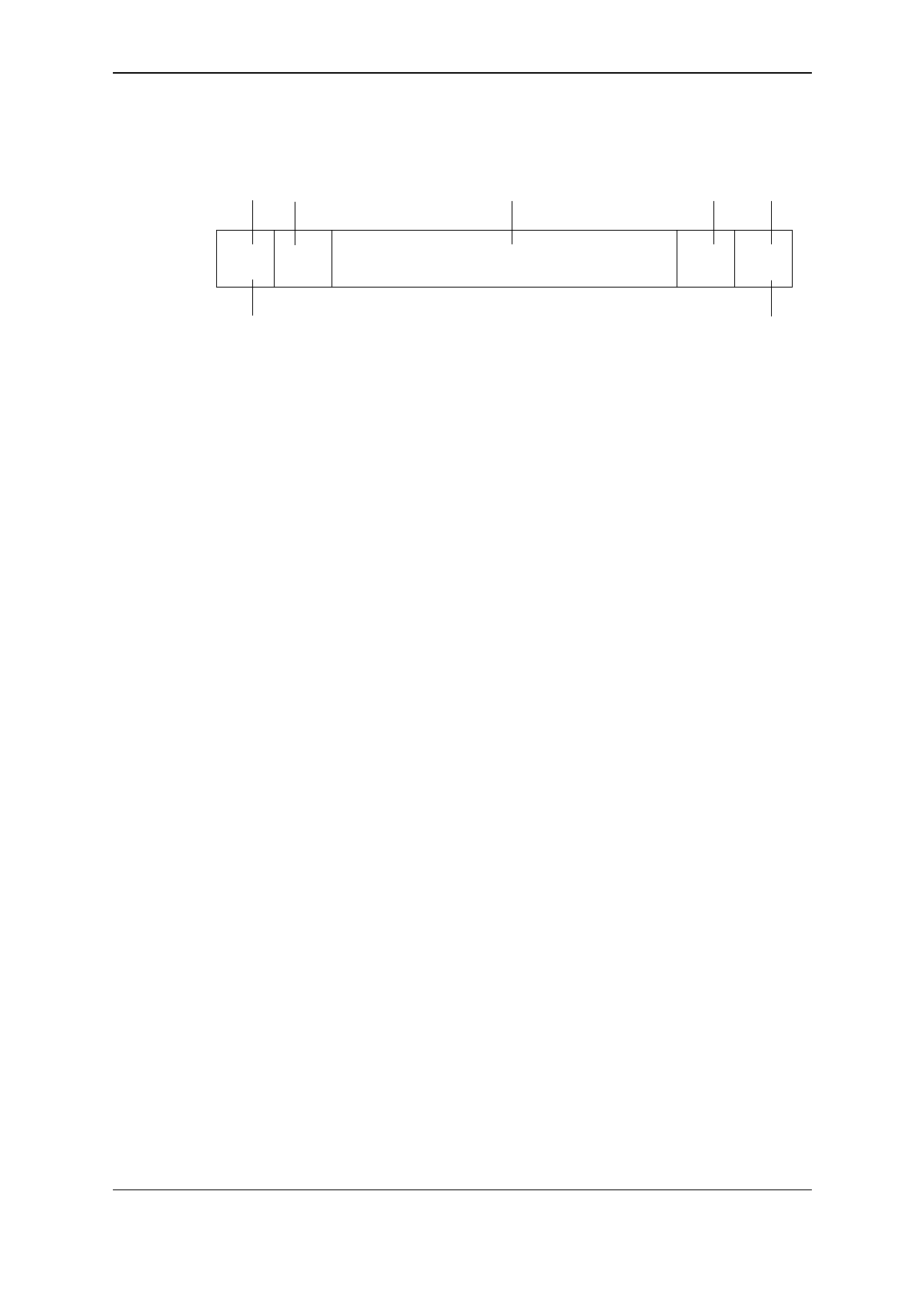
5-3
The following diagram shows a typical message structure.
LSB
Data Framing
Transmitted last
Framing
Transmitted first
Trailing
Parity
Leading
Parity
MSB
Framing bits are usually either not used or confined to start and stop
bits which have a fixed state. Some applications require a more
complicated sequence of framing bits, usually at the start of the
message.
Parity bits are used to check the integrity of the data message. Parity
may be odd or even and it may be calculated from the data only or
from the data and some framing bits.
Card data
Data from the card can be any number of bits including any parity
check bits which may be stored in the card code. The interface
selected determines whether the data is sent most significant bit first
or least significant bit first.
PINpad data
Data from a PINpad is sent whenever a key is pressed, providing the
Reader is not already sending a card data message, in which case it
sends the PINpad data afterwards. PINpad data has 8 data bits. The
first four bits are the inverse of the PINpad key, the second four bits
are the PINpad key. For example, if the data is 1010 0101, the key
pressed was 5. If the data is 0100 1011, the key pressed was #. (Hex
0 to 9 corresponds to keys 0 to 9, hex A is * and hex B is #.)
SM501 and SM501K Contactless Smartcard Reader
5-4
Magnetic Stripe
A Magnetic Stripe interface is provided which simulates the output of
a magnetic card reader.
Connections
The pin connections for the Magnetic Stripe interface are as follows:
0V (ground)
D0 (data)
D1 (strobe)
DA (present)
Electrical characteristics
The interface provides three outputs: Present, Data and Strobe.
Present is a signal given by a magnetic card reader indicating that a
card has been inserted in the slot. On the Readers, this signal
becomes active just before data is sent and is released after the data
has been sent.
Data is a signal whose level reflects the value of the bit in the code.
Strobe is a series of clock pulses. Data can be sampled on either the
rising edge or the falling edge of the Strobe signal.
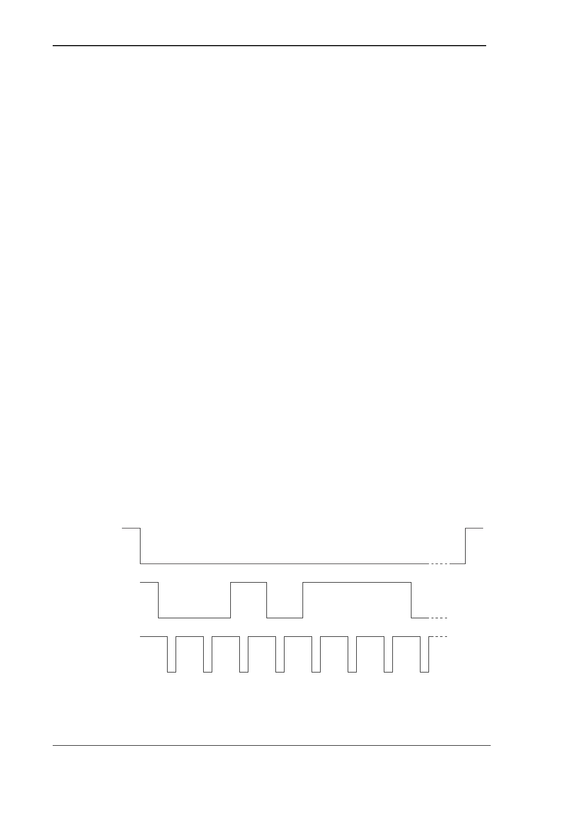
The following diagram should make clear the action of all three
signals in a data transfer. In this example, the Data line (D0) is high
for a one and low for a zero:
Present (DA)
Data (D0)
Strobe (D1)
Card number 0 0 010111

Data output
5-5
PINpad data
Data from a PINpad is sent whenever a key is pressed, providing the
Reader is not already sending a card data message, in which case it
sends the PINpad data afterwards. PINpad data has 8 data bits. The
first four bits are the inverse of the PINpad key, the second four bits
are the PINpad key. For example, if the data is 1010 0101, the key
pressed was 5. If the data is 0100 1011, the key pressed was #. (Hex
0 to 9 corresponds to keys 0 to 9, hex A is * and hex B is #.)
Whenever a key is pressed, the Strobe output pulses 8 times, and the
Data output should be sampled at each Strobe pulse to give the 8
data bits corresponding to the key that was pressed. Note that
PINpad data is not output as an ASCII character.
Custom interfaces
It is possible to configure your own interface: contact Technical
Support in Cambridge for details.

SM501 and SM501K Contactless Smartcard Reader
5-6

6-1
Chapter 6
Card data format
Chip serial number mode
This mode will work with any Mifare contactless smartcard regardless
of the data content and security keys used.
The Reader will read the first card it finds at the antenna and output
the chip serial number as its data.
The chip serial number is a number programmed into the card at the
time of manufacture which is guaranteed to be unique regardless of
the source or application of the card.
Girovend mode
This mode enables you to use cards that have been pre-programmed
by Girovend to work with their cashless vending systems.
The Girovend cards are programmed in accordance with the Mifare
application directory standard.
The Girovend cards contain a public access sector which contains,
among other things, an 8 bit “installation code”, an 8 bit “system
code” and an 18 bit “serial number”.
The Reader treats the system code in the same way as a Cotag
Distributor Code, and treats the installation code in the same way as
a Cotag Site Code, and treats the serial number in the same way as a
Cotag Card Number.
When reading cards, the Reader will interrogate all the cards
currently in range of the antenna one by one until a card is found
which contains Girovend data. If the installer code matches that
learnt by the Reader (see the section at the beginning of chapter 3 for
details of teaching the Reader a Distributor Code) then it outputs the
system code and serial number via the currently selected data
interface.
If the installer code does not match that learnt by the Reader, the
Reader will keep interrogating the rest of the cards.
SM501 and SM501K Contactless Smartcard Reader
6-2
Cotag mode
This mode uses smartcards which have been programmed with
Cotag’s own data, see below for details.
The Cotag cards are programmed in accordance with the Mifare
application directory standard.
A Cotag programmed card may contain one or more sectors of
information which may be either access control data or configuration
data. Every sector contains the distributor code.
When reading cards the reader will interrogate all the cards currently
in the range of the antenna one by one until a card is found which
contains Cotag data. If the Distributor Code matches that learnt by
the Reader (see the section at the beginning of chapter 3 for details
of teaching the Reader a Distributor Code) then the Reader reads and
processes each sector which is present .
Information contained in a Cotag smartcard
This section should be read with a good understanding of the
structure of the data in a Mifare contactless card, particularly the
structure of the MAD (Mifare Application Directory). (For this
information, see the Mifare standardisation note entitled “MIFARE
Application directory MAD”.)
Note: all numbers stored in a Cotag sector are stored most significant
byte first (this is is different from most other data in the card).
A Cotag programmed card may contain between one and three
sectors of information. Each sector has the Cotag AID (Application
Identifier) in the relevant position in the MAD. (Cotag’s AID is $4837,
that is: the $37th access control application ($48 = access control)
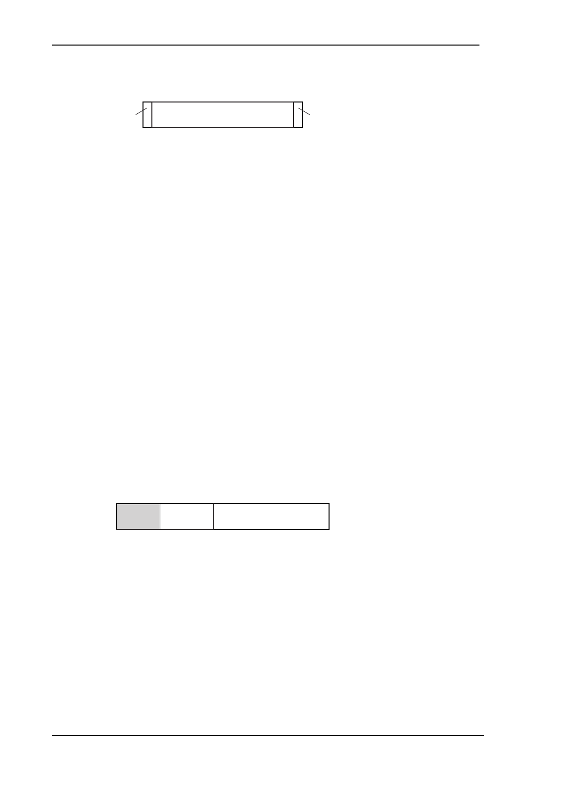
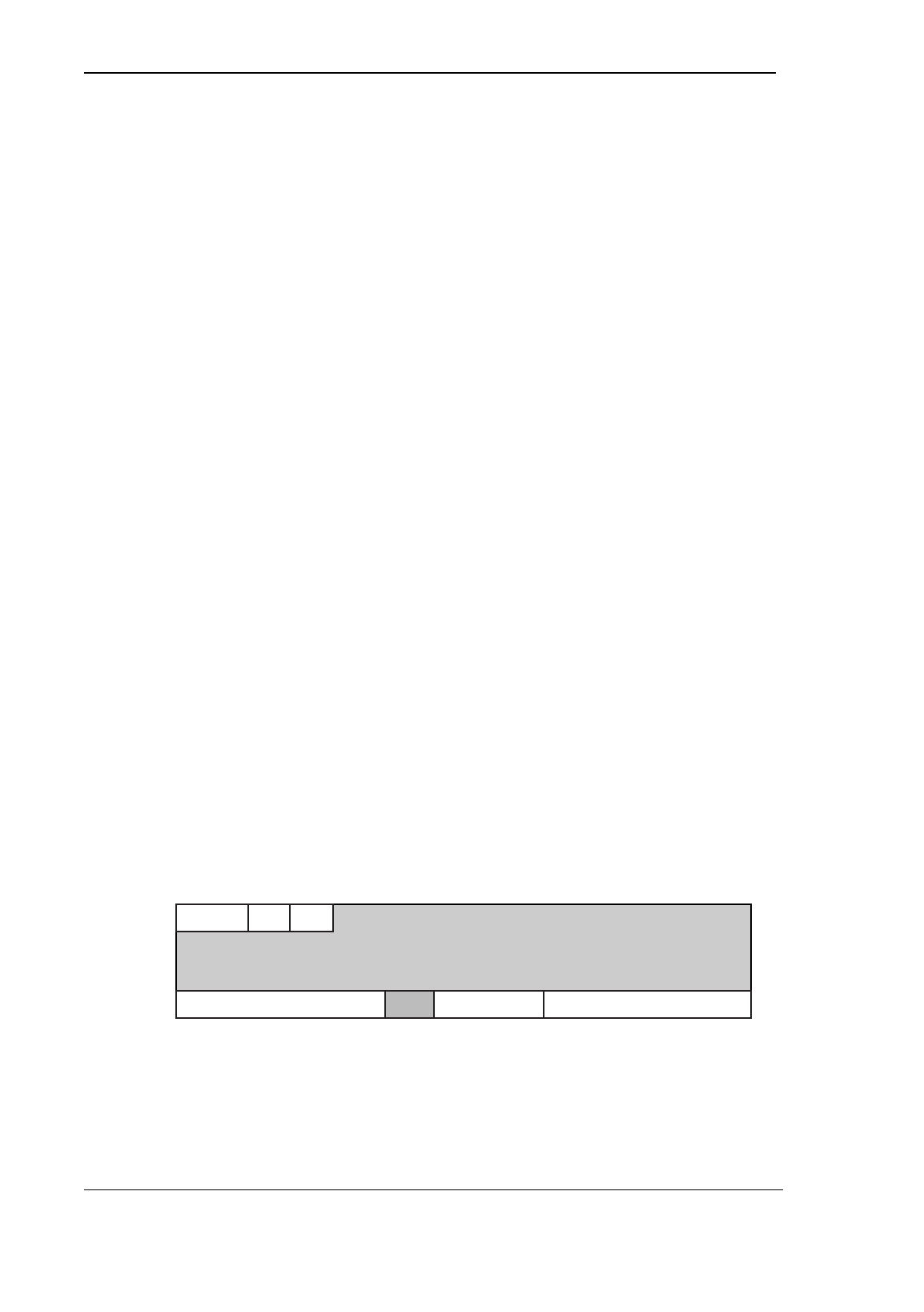
The sectors all have the following structure:
DC Type CS
44 bytes of data
1
64
Cotag Read key Cotag Write keyAccess bytes
DC - Distributor code
Card data format
6-3
Type - Type of sector - can be one of the folowing values
0 - Access control sector
1 - Configuration sector
2 - Configuration extension sector
CS - Checksum correction byte - this is calculated so that
the EOR of the first 48 bytes of the sector = $AA.
Data - This is the 44 bytes of sector data - its use use is
dictated by the sector type and is described in detail
below.
Cotag Read key - Cotag’s own secret read
key.
Cotag Write key - Cotag’s own secret write
key.
Access bytes - See GEMPLUS
“Contactless Serial
Readers Reference
Manual” for a description
of this area.
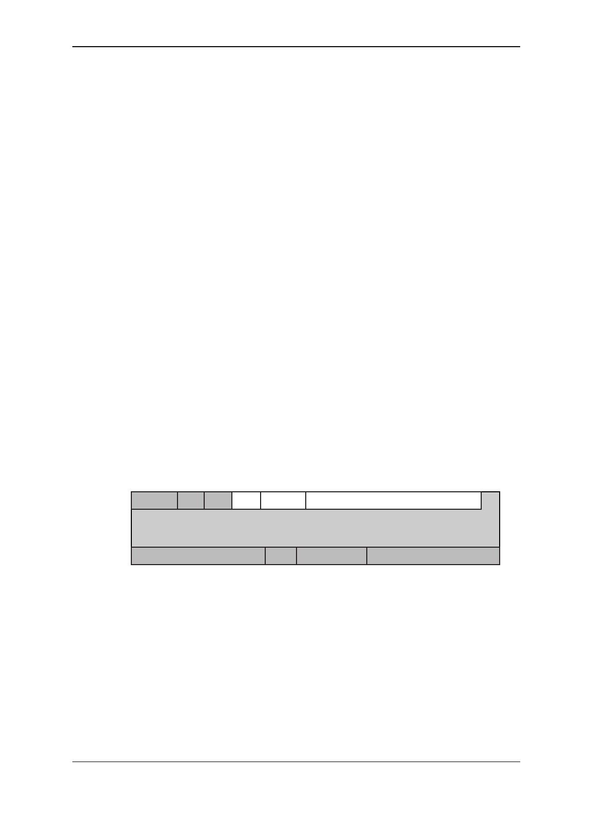
Sector type 0 - Access control
If this sector is present it must be the highest numbered Cotag sector
on a card (that is, it must come after any configuration sectors).
The data contained in this type of sector has the following structure:
1
64
CNIS SC
IS - 3 bit Issue state of card (0 - 7)
SC - 16 bit Site code of card (0 - 65,535)
CN - 64 bit Card number of card
(0 - 281,474,976,710,655)
Other sector types
Other sector types are defined which enable you to configure Reader
interface type 5. Contact Technical Support in Cambridge for details.

SM501 and SM501K Contactless Smartcard Reader
6-4