Beyerdynamic MCWD509 Wireless Conference System User Manual
Beyerdynamic Wireless Conference System
UserManual.wiki
>
Beyerdynamic
>
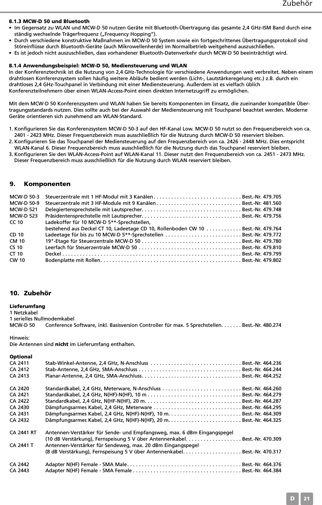
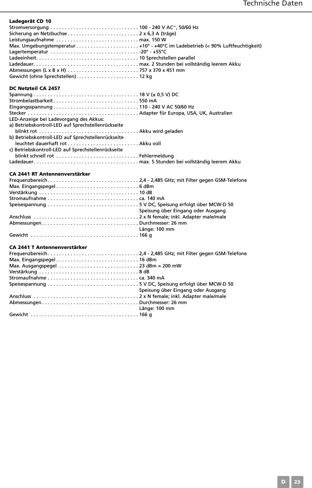
MCWD509 User Manual
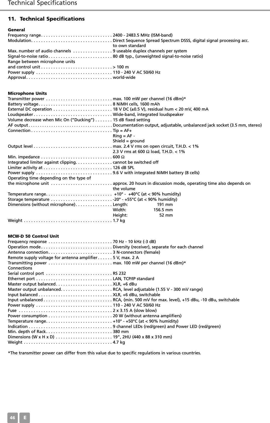
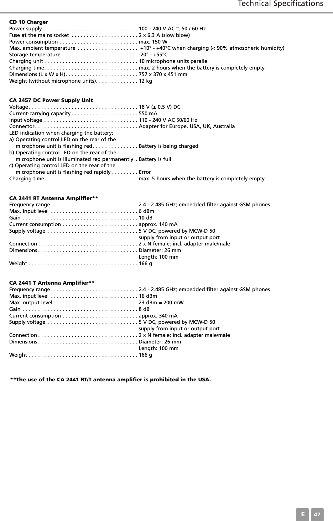
User Manual
Navigation menu
Upload a User Manual
Namespaces
Wiki Guide
HTML
PDF
Info
Views
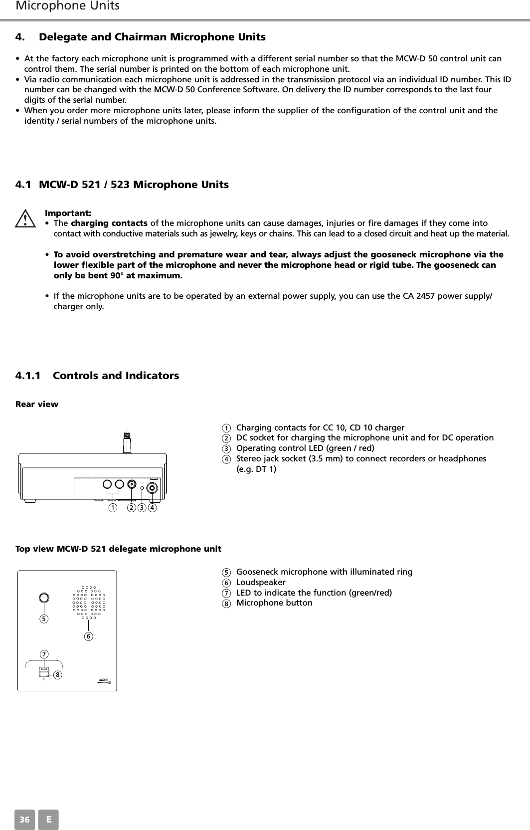
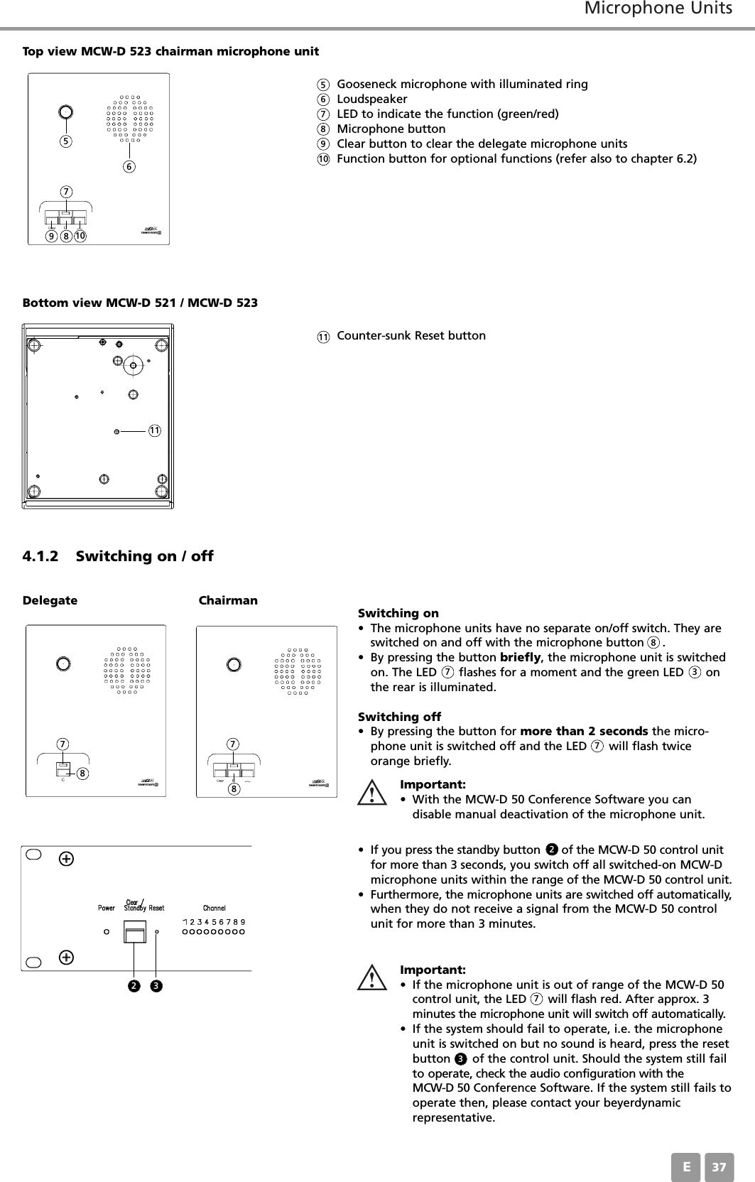
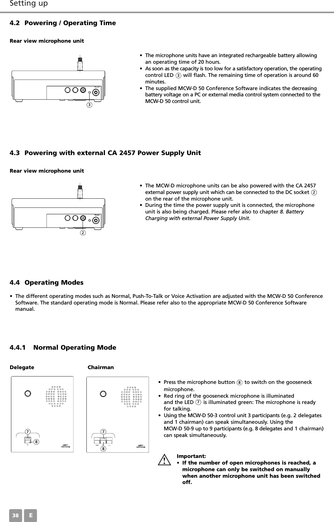
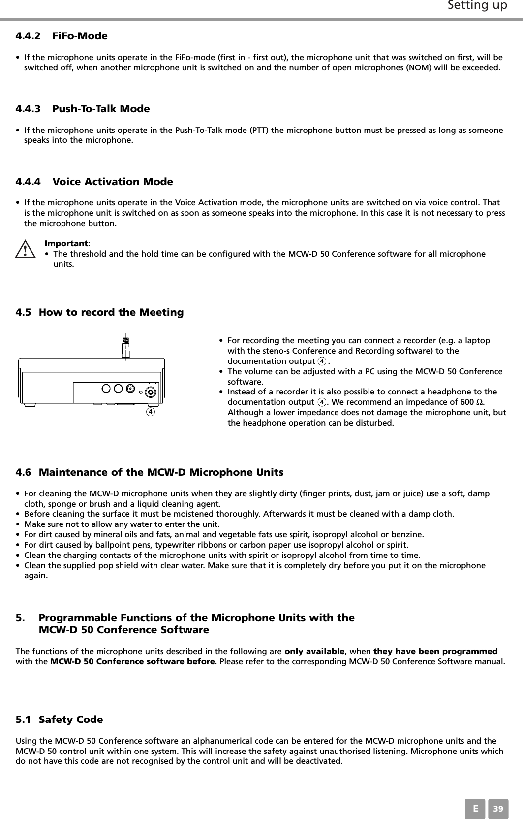
User Manual
Discussion / Help
Navigation