Beyerdynamic MCWD509 Wireless Conference System User Manual
Beyerdynamic Wireless Conference System
User Manual

MCW-D 50
BEDIENUNGSANLEITUNG
OPERATING INSTRUCTIONS
NOTICE D’UTILISATION
Konferenzsystem
Discussion System
Système de conférence digital sans fil

D
02
Hinweis
Diese Bedienungsanleitung wendet sich an technisch qualifiziertes Personal, das speziell auf dem Gebiet der Elektrotechnik
ausgebildet ist. Die Kenntnis und das technisch einwandfreie Umsetzen der in dieser Bedienungsanleitung enthaltenen
Hinweise sind Voraussetzung für eine problemlose Installation und Inbetriebnahme sowie für die Sicherheit beim Betrieb der
beschriebenen Produkte.
In dieser Anleitung wird nicht jeder denkbare Fall der Installation, des Betriebs oder der Instandhaltung behandelt. Für weitere
Informationen steht Ihnen Ihr beyerdynamic-Händler oder beyerdynamic GmbH & Co. KG zur Verfügung.
beyerdynamic GmbH & Co. KG übernimmt keine Haftung für in dieser Dokumentation enthaltene Fehler sowie für beiläufige
oder Folgeschäden im Zusammenhang mit der Bereitstellung, Darstellung oder Verwendung dieser Dokumentation und der
darin beschriebenen Programme oder Produkte.
Hinweise für eventuelle Rücksendungen
1. Um Beschädigungen zu vermeiden, versenden Sie die Sprechstellen vorzugsweise im Ladekoffer.
2. Falls einzelne Sprechstellen versendet werden sollen, verpacken Sie diese bitte so, dass keine schweren Gegenstände auf die
Schwanenhälse drücken können.

Inhalt
D03
Inhaltsverzeichnis
1. Allgemeine Sicherheitshinweise Steuerzentrale, Ladegerät und Sprechstellen . . . . . . . . . . . . . . . . . . . . Seite 4
2. Aufstellung . . . . . . . . . . . . . . . . . . . . . . . . . . . . . . . . . . . . . . . . . . . . . . . . . . . . . . . . . . . . . . . . . . . . . . . . Seite 5
3. Steuerzentrale MCW-D 50. . . . . . . . . . . . . . . . . . . . . . . . . . . . . . . . . . . . . . . . . . . . . . . . . . . . . . . . . . . . . Seite 6
3.1 Bedien- und Kontrollelemente . . . . . . . . . . . . . . . . . . . . . . . . . . . . . . . . . . . . . . . . . . . . . . . . . . . Seite 6
3.2 Inbetriebnahme. . . . . . . . . . . . . . . . . . . . . . . . . . . . . . . . . . . . . . . . . . . . . . . . . . . . . . . . . . . . . . . Seite 7
3.2.1 Aufstellen der Steuerzentrale . . . . . . . . . . . . . . . . . . . . . . . . . . . . . . . . . . . . . . . . . . . . . . . . . . . . Seite 7
3.2.2 Antennen anschließen . . . . . . . . . . . . . . . . . . . . . . . . . . . . . . . . . . . . . . . . . . . . . . . . . . . . . . . . . Seite 8
3.2.3 Audioanschluss . . . . . . . . . . . . . . . . . . . . . . . . . . . . . . . . . . . . . . . . . . . . . . . . . . . . . . . . . . . . . . . Seite 8
3.2.4 Netzanschluss . . . . . . . . . . . . . . . . . . . . . . . . . . . . . . . . . . . . . . . . . . . . . . . . . . . . . . . . . . . . . . . . Seite 8
3.2.5 Ein-/Ausschalten . . . . . . . . . . . . . . . . . . . . . . . . . . . . . . . . . . . . . . . . . . . . . . . . . . . . . . . . . . . . . . Seite 9
3.2.6 Kanal-Anzeige. . . . . . . . . . . . . . . . . . . . . . . . . . . . . . . . . . . . . . . . . . . . . . . . . . . . . . . . . . . . . . . . Seite 9
3.2.7 Rackmontage . . . . . . . . . . . . . . . . . . . . . . . . . . . . . . . . . . . . . . . . . . . . . . . . . . . . . . . . . . . . . . . . Seite 9
3.2.8 Lautstärkeregler . . . . . . . . . . . . . . . . . . . . . . . . . . . . . . . . . . . . . . . . . . . . . . . . . . . . . . . . . . . . . . Seite 9
3.2.9 Anschluss von Mediensteuersystem und PC . . . . . . . . . . . . . . . . . . . . . . . . . . . . . . . . . . . . . . . . . Seite 10
3.3 Anschließen abgesetzter Antennen . . . . . . . . . . . . . . . . . . . . . . . . . . . . . . . . . . . . . . . . . . . . . . . Seite 10
3.4 Fernspeisung der Antennensignalverstärker über Zentrale . . . . . . . . . . . . . . . . . . . . . . . . . . . . . Seite 11
4. Delegierten- und Präsidentensprechstellen . . . . . . . . . . . . . . . . . . . . . . . . . . . . . . . . . . . . . . . . . . . . . . . Seite 12
4.1 Sprechstellen MCW-D 521 / 523 . . . . . . . . . . . . . . . . . . . . . . . . . . . . . . . . . . . . . . . . . . . . . . . . . . Seite 12
4.1.1 Bedien- und Kontrollelemente . . . . . . . . . . . . . . . . . . . . . . . . . . . . . . . . . . . . . . . . . . . . . . . . . . . Seite 12
4.1.2 Ein-/Ausschalten . . . . . . . . . . . . . . . . . . . . . . . . . . . . . . . . . . . . . . . . . . . . . . . . . . . . . . . . . . . . . . Seite 13
4.2 Speisung / Betriebszeit . . . . . . . . . . . . . . . . . . . . . . . . . . . . . . . . . . . . . . . . . . . . . . . . . . . . . . . . . Seite 14
4.3 Speisung über externes Netzteil CA 2457 . . . . . . . . . . . . . . . . . . . . . . . . . . . . . . . . . . . . . . . . . . . Seite 14
4.4 Betriebsarten. . . . . . . . . . . . . . . . . . . . . . . . . . . . . . . . . . . . . . . . . . . . . . . . . . . . . . . . . . . . . . . . . Seite 14
4.4.1 Betriebsart Normal . . . . . . . . . . . . . . . . . . . . . . . . . . . . . . . . . . . . . . . . . . . . . . . . . . . . . . . . . . . . Seite 14
4.4.2 Override-Betrieb . . . . . . . . . . . . . . . . . . . . . . . . . . . . . . . . . . . . . . . . . . . . . . . . . . . . . . . . . . . . . . Seite 15
4.4.3 Push-To-Talk-Betrieb . . . . . . . . . . . . . . . . . . . . . . . . . . . . . . . . . . . . . . . . . . . . . . . . . . . . . . . . . . . Seite 15
4.4.4 Sprachaktivierter Betrieb . . . . . . . . . . . . . . . . . . . . . . . . . . . . . . . . . . . . . . . . . . . . . . . . . . . . . . . Seite 15
4.5 Aufzeichnen der Konferenz . . . . . . . . . . . . . . . . . . . . . . . . . . . . . . . . . . . . . . . . . . . . . . . . . . . . . Seite 15
4.6 Pflege der MCW-D Sprechstellen . . . . . . . . . . . . . . . . . . . . . . . . . . . . . . . . . . . . . . . . . . . . . . . . . Seite 15
5. Programmierbare Sprechstellenfunktionen mit MCW-D 50 Conference Software. . . . . . . . . . . . . . . . . . Seite 15
5.1 Sicherheitscode . . . . . . . . . . . . . . . . . . . . . . . . . . . . . . . . . . . . . . . . . . . . . . . . . . . . . . . . . . . . . . . Seite 15
5.2 Programmierbare Funktionstaste Präsidentensprechstelle MCW-D 523. . . . . . . . . . . . . . . . . . . . Seite 16
5.3 Betriebsart Anmeldung. . . . . . . . . . . . . . . . . . . . . . . . . . . . . . . . . . . . . . . . . . . . . . . . . . . . . . . . . Seite 17
6. Ladegerät CD 10 im Koffer CC 10 . . . . . . . . . . . . . . . . . . . . . . . . . . . . . . . . . . . . . . . . . . . . . . . . . . . . . . . Seite 17
6.1 Erstinbetriebnahme. . . . . . . . . . . . . . . . . . . . . . . . . . . . . . . . . . . . . . . . . . . . . . . . . . . . . . . . . . . . Seite 17
6.2 Ladevorgang . . . . . . . . . . . . . . . . . . . . . . . . . . . . . . . . . . . . . . . . . . . . . . . . . . . . . . . . . . . . . . . . . Seite 17
7. Akkuladung über externes Netzteil . . . . . . . . . . . . . . . . . . . . . . . . . . . . . . . . . . . . . . . . . . . . . . . . . . . . . Seite 18
8. Problemlösung . . . . . . . . . . . . . . . . . . . . . . . . . . . . . . . . . . . . . . . . . . . . . . . . . . . . . . . . . . . . . . . . . . . . . Seite 18
8.1 Gleichzeitiger Betrieb des MCW-D Konferenzsystems mit anderen 2,4 GHz Geräten . . . . . . . . . Seite 19
9. Komponenten . . . . . . . . . . . . . . . . . . . . . . . . . . . . . . . . . . . . . . . . . . . . . . . . . . . . . . . . . . . . . . . . . . . . . . Seite 21
10. Zubehör . . . . . . . . . . . . . . . . . . . . . . . . . . . . . . . . . . . . . . . . . . . . . . . . . . . . . . . . . . . . . . . . . . . . . . . . . . . Seite 21
11. Technische Daten. . . . . . . . . . . . . . . . . . . . . . . . . . . . . . . . . . . . . . . . . . . . . . . . . . . . . . . . . . . . . . . . . . . . Seite 22
Konformitätserklärung . . . . . . . . . . . . . . . . . . . . . . . . . . . . . . . . . . . . . . . . . . . . . . . . . . . . . . . . . . . . . . . Seite 72

Sicherheitshinweise
D
04
1. Allgemeine Sicherheitshinweise Steuerzentrale und Ladegerät
• LESEN Sie die Bedienungsanleitung/Produktinformation.
• BEWAHREN Sie diese Bedienungsanleitung/Produktinformation auf.
• BEFOLGEN Sie die aufgeführten Bedienungs- und Sicherheitshinweise.
• Das Gerät muss so aufgestellt werden, dass die Steckverbindung leicht zugänglich ist.
• Das Gerät muss an eine Netz-Steckdose mit Schutzkontakt angeschlossen werden.
• Setzen Sie das Gerät niemals Regen oder hoher Feuchtigkeit aus. Installieren Sie es daher nicht in unmittelbarer Nähe von
Swimming Pools, Duschanlagen, feuchten Kellerräumen oder sonstigen Bereichen mit außergewöhnlich hoher
Luftfeuchtigkeit.
• Stellen Sie niemals mit Flüssigkeiten gefüllte Gegenstände (z.B. Vasen oder Trinkgläser) auf das Gerät. Flüssigkeiten in den
Geräten können einen Kurzschluss verursachen.
• Reinigen Sie das Gerät nur mit einem leicht feuchten oder trockenem Tuch. Verwenden Sie niemals Lösungsmittel, da diese
die Oberfläche beschädigen.
• Installieren und betreiben Sie das Gerät auch niemals in unmittelbarer Nähe von Heizkörpern, Beleuchtungsanlagen oder
anderen wärmeerzeugenden Geräten.
• Verlegen Sie alle Kabel stets so, dass sie nicht durch scharfe Gegenstände geknickt oder gar durchgetrennt werden können.
• Verlegen Sie alle Anschlusskabel so, dass niemand darüber stolpern und sich verletzen kann.
• Schalten Sie bei allen Arbeiten an den Ein- und Ausgängen die Stromzufuhr aus.
• Überprüfen Sie, ob die Anschlusswerte mit der vorhandenen Netzstromversorgung übereinstimmen. Bei Anschluss des
Systems an die falsche Stromversorgung können ernsthafte Schäden entstehen. Eine falsche Netzspannung kann das Gerät
beschädigen oder einen elektrischen Schlag verursachen.
• Dieses Gerät benötigt eine ausreichende Ventilation. Decken Sie die Lüftungsöffnungen nicht ab. Wenn die Eigenwärme
nicht abgeführt wird, kann das Gerät beschädigt oder brennbare Materialien in unmittelbarer Nähe können entzündet wer-
den. Achten Sie daher darauf, dass die Luft durch die Lüftungsöffnungen frei zirkulieren kann und halten Sie brennbare
Materialien fern.
• Stellen Sie niemals offene Brandquellen (z.B. Kerzen) auf das Gerät.
• Wenn Sie das Gerät an einen anderen Ort transportieren, achten Sie darauf, dass es ausreichend gesichert ist und niemand
durch ein eventuelles Herunterfallen oder Stoßen am Gerät verletzt werden kann.
• Nehmen Sie das Gerät bei einem Gewitter oder wenn Sie es längere Zeit nicht benutzen, vom Netz.
• Wenn durch das Gerät eine Sicherung defekt oder ein Kurzschluss verursacht wurde, nehmen Sie es vom Netz und lassen Sie
es überprüfen und reparieren.
• Öffnen Sie nicht eigenmächtig das Gerät. Sie könnten einen elektrischen Schlag erleiden. Überlassen Sie alle Servicearbeiten
nur autorisiertem Fachpersonal.
• Fassen Sie das Netzkabel nicht mit nassen Händen an und an den Kontaktstiften sollte sich kein Wasser oder Staub befinden.
In beiden Fällen könnten Sie einen elektrischen Schlag erleiden.
• Das Netzkabel muss fest angeschlossen sein. Ist es lose, besteht Brandgefahr.
• Ziehen Sie das Netzkabel immer am Stecker vom Netz und/oder vom Gerät - niemals am Kabel. Das Kabel könnte beschädigt
werden und einen elektrischen Schlag oder Brand verursachen.
• Wenn das Netzkabel angeschlossen ist, bringen Sie das Gerät nicht mit anderen metallischen Gegenständen in Berührung.
• Stecken Sie keine Gegenstände in die Lüftungs- und andere Öffnungen. Sie könnten das Gerät beschädigen und/oder sich
verletzen.
• Setzen Sie das Gerät nicht ein, wenn der Netzstecker beschädigt ist.
• Entfernen Sie auf keinen Fall den Schaumstoff aus dem Ladegerät CD 10. Im Innern des Ladegerätes befinden sich keine war-
tungsfähigen Teile.
• Das Ladegerät wurde zur Ladung der Akkus in den MCW-D Sprechstellen ausgelegt. Laden Sie daher nur MCW-D
Sprechstellen und keine anderen akku- oder batteriebetriebenen Geräte auf. Die Akkus oder Batterien könnten explodieren
und Sie verletzen bzw. das Gerät beschädigen.
• Wenn Sie das Ladegerät mit Zubehör verwenden, das nicht für dieses entwickelt wurde, kann dies einen Brand, elektrischen
Schlag oder eine Körperverletzung zur Folge haben.
• Versuchen Sie niemals das Ladegerät selbst zu reparieren. Es besteht die Gefahr, einen elektrischen Schlag zu erleiden oder
einen Brand auszulösen.
• Setzen Sie das Ladegerät niemals als Netz- oder Speiseteil für elektrische Geräte ein.
Sicherheitsinfos für Sprechstellen
• Sprechstellen mit einem Metallgehäuse sind schwer. Platzieren Sie diese Sprechstellen daher immer so, dass sie nicht her-
unterfallen können. Sie könnten sich oder andere verletzen bzw. die Sprechstelle beschädigen.
• Verfügt die Sprechstelle über ein Schwanenhalsmikrofon, passen Sie auf, dass Sie sich an diesem nicht verletzen, z.B. ins
Auge bohren.
• Die Ladekontakte der MCW-D Sprechstellen können Sachbeschädigungen, Verletzungen oder Brandschäden verursachen,
wenn die Kontakte mit leitenden Materialien wie Schmuck, Schlüsseln oder Ketten in Berührung kommen. Dies kann zu
einem geschlossenen Stromkreis und dadurch zur Erhitzung des Materials führen. Um einen solchen ungewollten Stromkreis
zu vermeiden, müssen die Ladekontakte mit Vorsicht behandelt werden. Dies gilt insbesondere dann, wenn die Sprechstellen
in einer Tasche oder einem anderen Behälter zusammen mit metallischen Gegenständen transportiert werden.
• Zum Ausrichten des Schwanenhalsmikrofons der Sprechstelle und zum Vermeiden einer Überdehnung und früh-
zeitigen Verschleißerscheinungen, fassen Sie das Mikrofon immer am unteren flexiblen Teilstück an, niemals
oben am Mikrofonkopf oder am starren Rohr. Der Schwanenhals darf nur bis max. 90 Grad gebogen werden.
• Wenn Sie die Sprechstellen im Ladegerät aufladen, achten Sie darauf, dass Sie sich beim Einsetzen oder Herausnehmen der
Sprechstellen nicht verletzen.

Hinweise zur Aufstellung
D05
2. Aufstellung
Die Steuerzentrale MCW-D 50 ist zur Aufstellung auf einen Tisch bzw. zum Einbau in ein 19"-Rack vorgesehen. Bei der
Aufstellung müssen Sie die Sicherheitsinformationen in Kapitel 1 beachten.
Insbesondere und darüber hinaus
• darf die Umgebungstemperatur am Aufstellungsort 40°C nicht überschreiten.
• darf der Aufstellungsort keiner übermäßigen Staub- und Feuchtigkeitsentwicklung ausgesetzt sein.
• sollte das Gerät keiner direkten Sonneneinstrahlung ausgesetzt sein.
• müssen die Anschlüsse vor direktem Zugriff während des Betriebes geschützt sein.
• müssen die Zuleitungen gegebenenfalls durch extern anzubringende Vorrichtungen zugentlastet werden.
• muss der Aufstellungsort vor Vibrationen geschützt sein.
• Schalten Sie das Ladegerät erst ein, nachdem Sie alle Sprechstellen eingesetzt haben. Leere Ladefächer sollten Sie während
des Ladevorgangs auf keinen Fall berühren. Sie könnten einen elektrischen Schlag erleiden.
• Vermeiden Sie eine Tiefentladung der Sprechstellenakkus. Die Akkus könnten beschädigt werden und die Lebensdauer der
Batterien kann sich verkürzen.
• Wenn akku- oder batteriebetriebene Geräte längere Zeit nicht eingesetzt werden (z.B. 1 Jahr), kann sich die Selbstentladung
der Batterie/Akku beschleunigen. Die Temperatur bei einer Langzeitaufbewahrung sollte zwischen +10°C und +30°C betra-
gen.
• Setzen Sie die Sprechstellen mehrere Monate nicht ein, sollten Sie die Akkus in den Sprechstellen mindestens zweimal pro
Jahr aufladen, um ein Auslaufen sowie eine Verschlechterung in der Leistung durch Selbstentladung verhindern.
Steuerzentrale MCW-D 50
D
06
Sie haben sich für das drahtlose, digitale Konferenzsystem MCW-D 50 von beyerdynamic entschieden. Wir danken für Ihr
Vertrauen. Nehmen Sie sich bitte einige Minuten Zeit und lesen Sie diese Bedienungsanleitung vor Inbetriebnahme aufmerk-
sam durch.
In dieser Bedienungsanleitung werden die Installation und Bedienung des Systems ohne Steuerung und Konfiguration über
einen PC beschrieben.
Folgende Komponenten gehören zur Grundausstattung eines Systems für den Betrieb ohne PC:
• Steuerzentrale MCW-D 50
• Delegiertensprechstelle MCW-D 521
• Präsidentensprechstelle MCW-D 523
Die Steuerzentrale MCW-D 50 ist in zwei Versionen lieferbar:
MCW-D 50-3 für Konferenzen, bei denen bis zu 3 Redner (z.B. 2 Delegierte und 1 Präsident) gleichzeitig sprechen können.
MCW-D 50-9 für Konferenzen, bei denen bis zu 9 Redner (z.B. 7 Delegierte und 2 Präsidenten) gleichzeitig sprechen können.
Weitere Informationen zur Steuerung und Konfiguration des MCW-D 50 Systems über einen PC finden Sie in der
Bedienungsanleitung „MCW-D 50 Conference Software“.
3. Steuerzentrale MCW-D 50
Die Steuerzentrale MCW-D 50 ist das Herzstück des Systems. Mit ihr werden die Delegierten- und Präsidentensprechstellen
gesteuert. Mit der Standardausführung der Steuerzentrale MCW-D 50 können maximal 3 Redner (z.B. 2 Delegierte und 1
Präsident) gleichzeitig sprechen.
3.1 Bedien- und Kontrollelemente
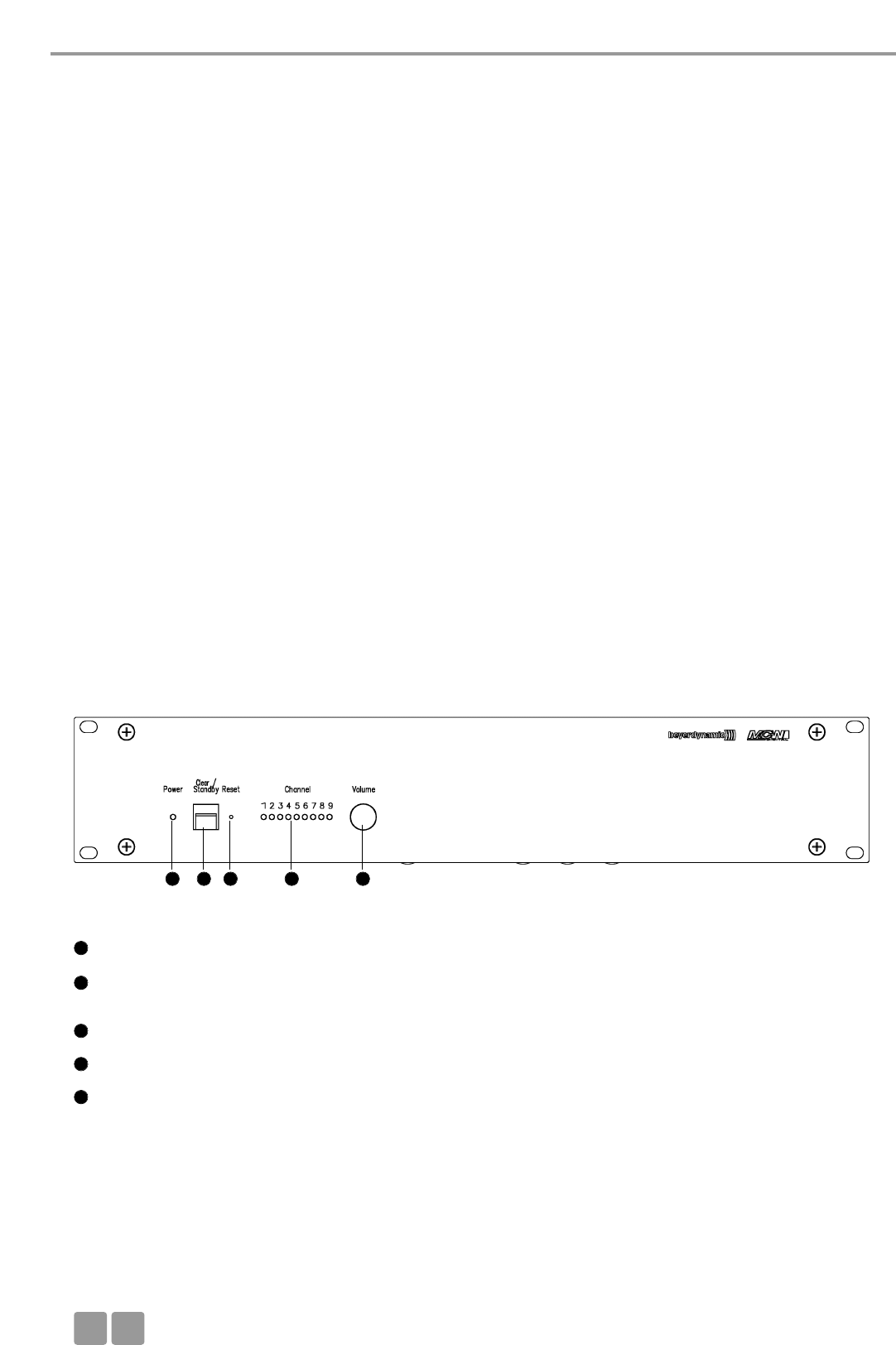
Vorderseite
Power-LED. LED leuchtet grün: Gerät ist eingeschaltet und betriebsbereit
Stand-By-Taster. Bei längerem Drücken (> 3 Sekunden) werden alle eingeschalteten Sprechstellen im Empfangsbereich
abgeschaltet. Bei kurzem Drücken werden alle zugeteilten Mikrofone abgeschaltet.
Reset, setzt die Anlage in den Einschaltzustand zurück. (Versenkter Taster, z.B. mit Büroklammer bedienen.)
LEDs für Status der Empfangskanäle. LED leuchtet grün: Kanal frei. LED leuchtet rot: Kanal belegt.
Lautstärkeregler für Sprechstellenlautsprecher
1
1
2
3
4
5
2 3 4 5
Steuerzentrale MCW-D 50
D07
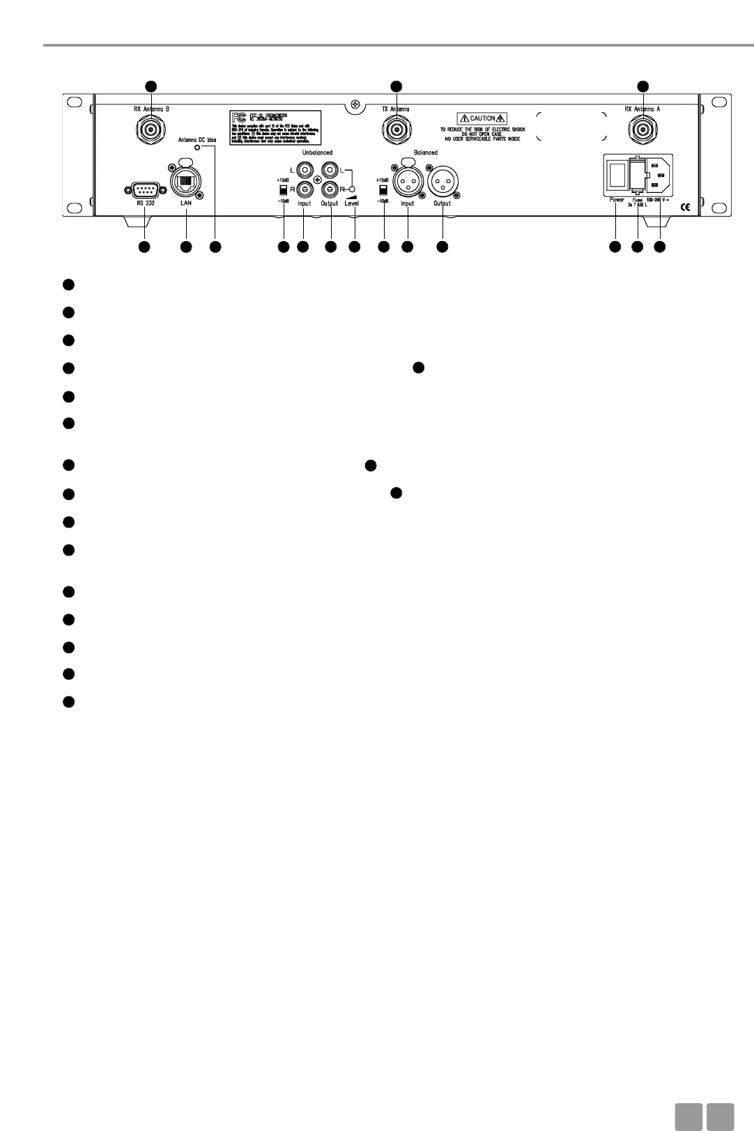
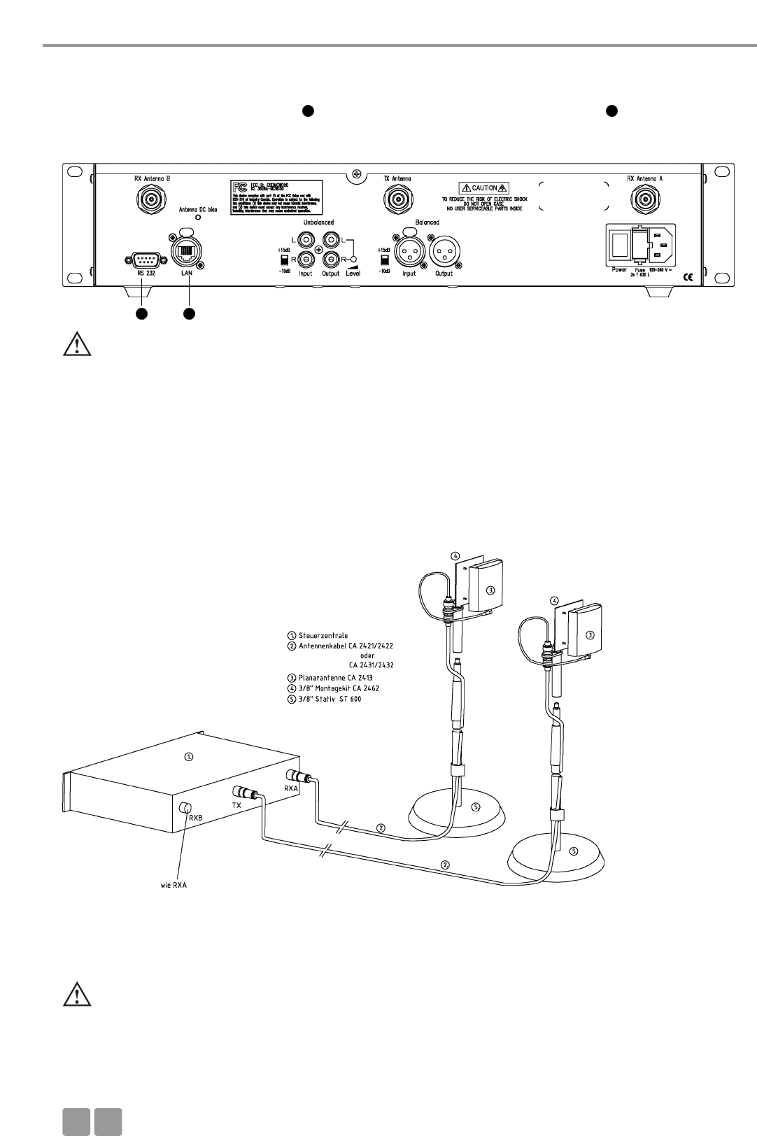
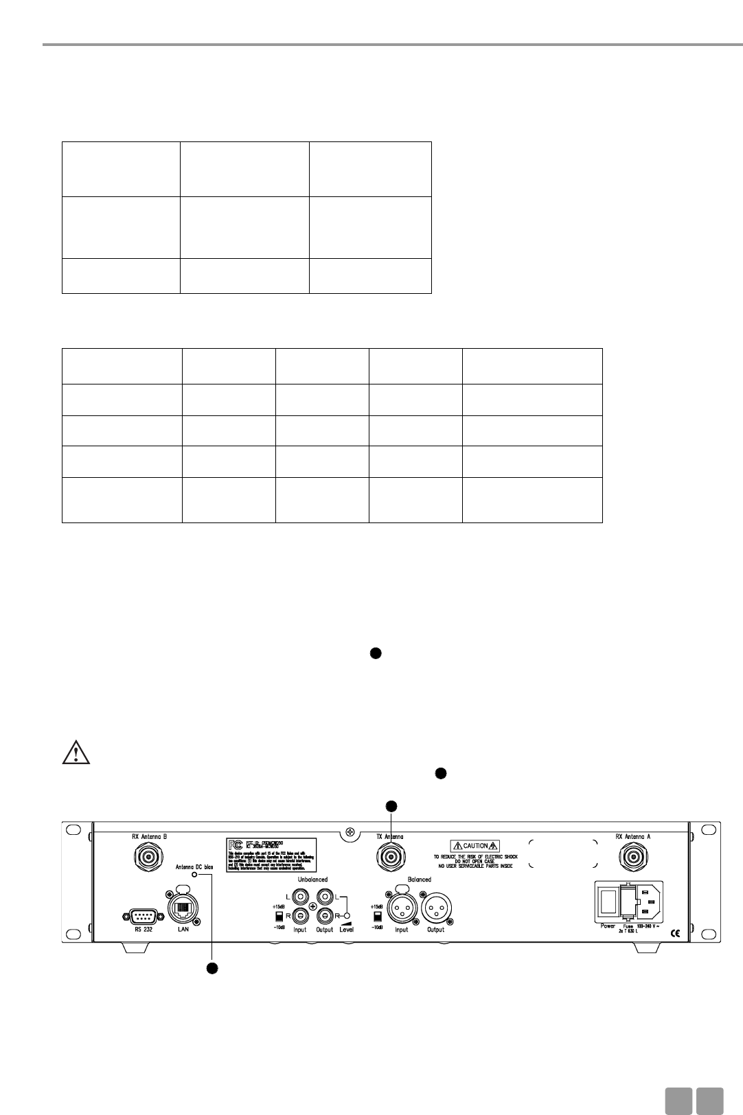
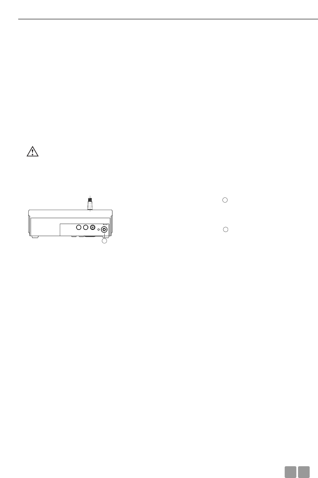
Serielle Schnittstelle RS 232 für Anschluss von z.B. PC oder Mediensteuerung (9-pol. Sub-D)
LAN-Anschluss für PC (Netzwerk)
Kontroll-LED für Antennenspeisung 5 V DC (grün = DC normal; schnelles rotes Blinken = Kurzschluss)
Schalter -10 dB / +15 dB für unsymmetrischen Eingang (Cinch)
Input = Eingang, Cinch, unsymmetrisch, zum Anschluss externer Geräte wie z.B. CD-Player (L + R)
Output - Summenausgang, Cinch, unsymmetrisch, zum Anschluss externer Geräte wie z.B. Mischpult,
Beschallungsanlage oder Aufnahmegerät (L + R)
Pegelsteller für Master Out - Summenausgang, Cinch
Schalter -10 dB / +15 dB für symmetrischen Eingang (XLR)
Input = Eingang. 3-pol. XLR female, symmetrisch, zum Einschleifen externer Signalquellen (+6 dBm)
Output - Summenausgang, 3-pol. XLR male, symmetrisch, zum Anschluss externer Geräte wie z.B. Mischpult,
oder Beschallungsanlage
Ein-/Ausschalter
Netzsicherung
Netzanschluss
Anschluss für Empfangsantennen
Anschluss für Sendeantenne
6
7
8
9
10
10
10
11
11
12
13
14
14
15
16
17
18
19
20
Rückseite
3.2 Inbetriebnahme
3.2.1 Aufstellen der Steuerzentrale
• Wenn Sie keine abgesetzten Antennen verwenden, stellen Sie die Steuerzentrale MCW-D 50 in dem Raum auf, in dem die
Konferenz stattfindet. Bei abgesetzten Antennen, stellen Sie die Antennen in dem Raum auf, in dem die Konferenz stattfin-
det.
• Stellen Sie die Steuerzentrale MCW-D 50 nicht neben digital gesteuerte Geräte.
6 7 11 12 13 14 15 16 17 18
192019
98
Steuerzentrale MCW-D 50
D
08
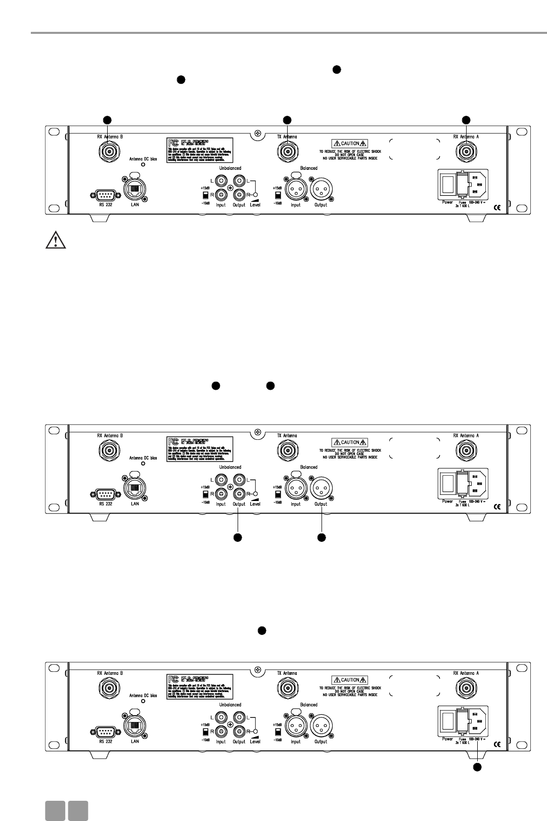
3.2.2 Antennen anschließen
• Schließen Sie die Empfangsantennen an die Antenneneingänge A und B an.
• Schließen Sie die Sendeantenne an.
• Für den Stand-Alone-Betrieb empfehlen wir die Stabwinkelantennen CA 2411.
3.2.3 Audioanschluss
• Verbinden Sie den Summenausgang XLR oder Cinch der Steuerzentrale MCW-D 50 mit dem Eingang eines Mischpultes
/ Mischverstärkers.
• Achten Sie darauf, dass die Kabel nicht geknickt oder durchtrennt werden können.
3.2.4 Netzanschluss
• Überprüfen Sie, ob die Anschlusswerte mit der vorhandenen Netzstromversorgung übereinstimmen. Bei Anschluss des
Systems an die falsche Stromversorgung können ernsthafte Schäden entstehen.
• Achten Sie darauf, dass das Netzkabel nicht geknickt oder durchtrennt werden kann.
• Schließen Sie die Steuerzentrale MCW-D 50 ans Netz an. Das Netzteil der Steuerzentrale kann sich automatisch auf eine
Wechselspannung zwischen 100 und 240 Volt bei 50 - 60 Hz einstellen.
Wichtig:
•Antennen und Sprechstellen sollten Sichtkontakt haben, d.h. zwischen der Steuerzentrale MCW-D 50 und
den Sprechstellen dürfen keine Hindernisse sein. Bei Sichtverbindung zwischen Steuerzentrale und Sprechstelle
sowie den Stabwinkelantennen beträgt die Reichweite ca. 30 - 50 m innerhalb geschlossener Räume. Für die
optimale Reichweite spielt auch die Oberflächenbeschaffenheit des Tisches eine Rolle. Ideal sind Holz- oder
Kunststofftische, bei Metalltischen ist unter Umständen die Abstrahlung und damit die max. erzielbare Reichweite
beeinträchtigt.
15 11
1920
20
19
19
11 15
18
18
Steuerzentrale MCW-D 50
D09
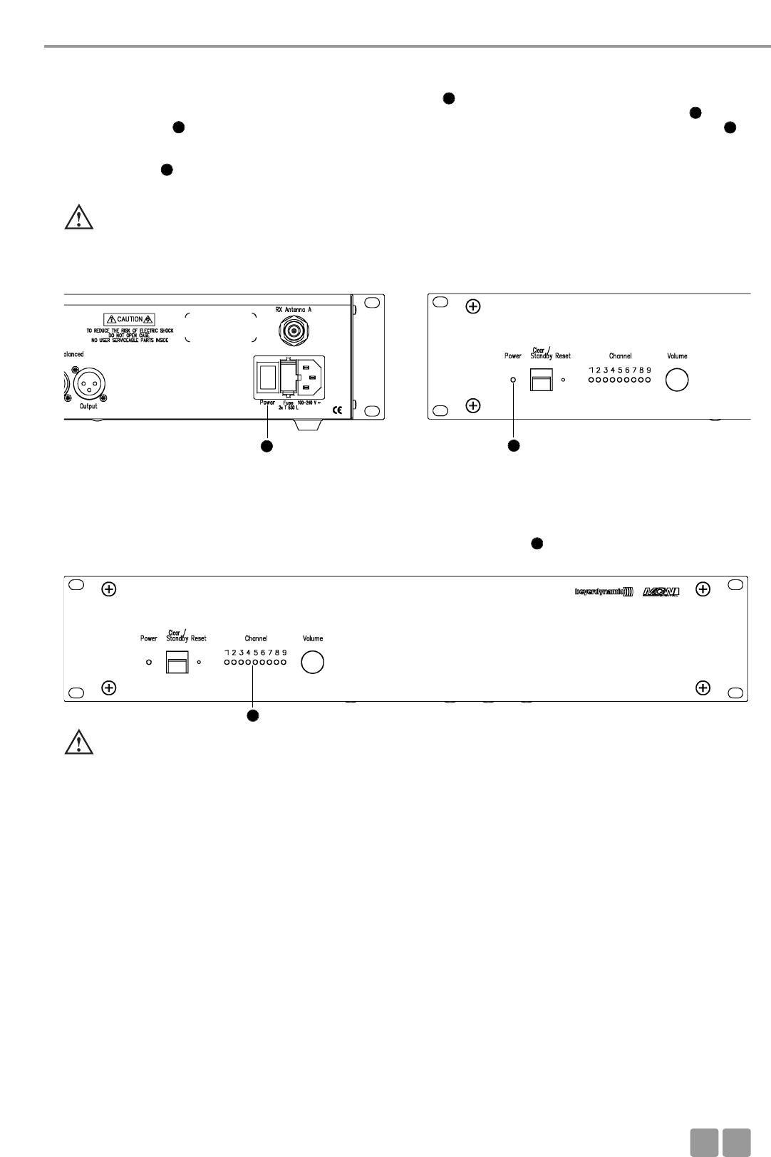
3.2.5 Ein-/Ausschalten
• Schalten Sie die Steuerzentrale MCW-D 50 mit dem Ein-/Ausschalter auf der Rückseite ein oder aus.
• Während der ersten ca. 30 Sekunden wird die Steuerzentrale MCW-D 50 initialisiert, dabei blinken die Power LED sowie
die Channel-LEDs rot. In dieser Zeit ist kein Betrieb möglich. Ist die Steuerzentrale MCW-D 50 über den LAN-Anschluss
an einem Netzwerk angeschlossen, beträgt die Zeitspanne bis die Steuerzentrale MCW-D 50 betriebsbereit ist ca. 20
Sekunden.
• Die Power LED auf der Vorderseite leuchtet grün, wenn die Steuerzentrale betriebsbereit ist.
•Achtung: Schalten Sie bei allen Arbeiten an den Ein- und Ausgängen das Gerät immer aus.
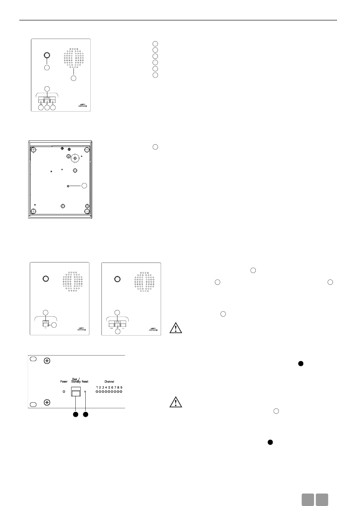
Rückseite Vorderseite
3.2.6 Kanal-Anzeige
• Je nach Bestückung der Steuerzentrale MCW-D 50 leuchten 3 oder mehr Kanal-LEDs grün (Standard: 3 Kanäle).
3.2.7 Rackmontage
• Bei Montage in ein 19"-Rackgehäuse sollte über und unter der MCW-D 50 Steuerzentrale ein Lüftungsfeld von 1 HE montiert
werden.
3.2.8 Lautstärkeregler
• Die Sprechstellenlautstärke wird zusammen mit dem virtuellen Regler in der MCW-D 50 Conference Software geregelt.
Wichtig:
• Leuchten nicht mehr als 3 LEDs bei einer mit mehr als einem HF-Modul bestückten Steuerzentrale, überprüfen Sie, ob
mit der MCW-D 50 Conference Software einzelne Module deaktiviert wurden.
16
1
1
47
4
16 1
4
Steuerzentrale MCW-D 50
D
10
3.2.9 Anschluss von Mediensteuersystem und PC
• Wenn Sie sowohl ein Mediensteuersystem als auch einen PC an die Steuerzentrale MCW-D 50 anschließen möchten, schließen
Sie den PC an den LAN-Netzwerkanschluss und das Mediensteuersystem an den RS 232-Anschluss an.
• Für die direkte Verbindung des LAN-Netzwerkanschlusses mit einem PC muss ein „Crossover“-Kabel verwendet werden.
• Die LAN-Einstellungen sind im Protokoll der MCW-D 50 Conference Software erläutert.
3.3 Anschließen abgesetzter Antennen
Die Steuerzentrale MCW-D 50 kann auch mit abgesetzten Antennen betrieben werden. Als Anschlusskabel dienen dämpfungs-
arme Kabel in verschiedenen Längen. Beachten Sie, dass Antennen abgesetzt montiert werden müssen. Durch den Einsatz einer
gerichteten Antenne (z.B. CA 2413, Gewinn ca. 6 dB) kann die Reichweite verbessert werden.
Je nach Kabeldämpfung sollten Sie ab einer bestimmten Antennenkabellänge Antennenverstärker einsetzen.
Die Planarantenne CA 2413 wird an die Steuerzentrale MCW-D 50 angeschlossen und mit dem Montagekit CA 2462 auf einem
Stativ befestigt. Weitere Installationsmöglichkeiten der Antennen finden Sie in unserem „MCW-D Design-Guide“.
Beispiel für variablen Aufbau mit abgesetzten Antennen
Wichtig:
•Antennen und Sprechstellen sollten Sichtkontakt haben, d.h. zwischen der Steuerzentrale MCW-D 50 und
den Sprechstellen dürfen keine Hindernisse sein. Bei Sichtverbindung zwischen Steuerzentrale und Sprechstelle
sowie den Stabwinkelantennen beträgt die Reichweite ca. 30 - 50 m innerhalb geschlossener Räume. Für die
optimale Reichweite spielt auch die Oberflächenbeschaffenheit des Tisches eine Rolle. Ideal sind Holz- oder
Kunststofftische, bei Metalltischen ist unter Umständen die Abstrahlung und damit die max. erzielbare Reichweite
beeinträchtigt.
Wichtig:
• Greifen Sie nie gleichzeitig mit der Mediensteuerung und der MCW-D 50 Conference Software auf die Steuerzentrale
MCW-D 50 zu. In diesem Fall kann eine korrekte Funktion des Systems nicht gewährleistet werden.
6 7
7 6
Steuerzentrale MCW-D 50
D11
3.4 Fernspeisung der Antennensignalverstärker über Zentrale
Die Antennensignalverstärker können über die Steuerzentrale MCW-D 50 ferngespeist werden. Auf der Rückseite der
Steuerzentrale MCW-D 50 befindet sich eine Diagnose-LED .
Diese LED leuchtet grün, wenn die Fernspeisespannung an allen Antennenbuchsen 5 V beträgt.
Die LED blinkt schnell rot, wenn an einer oder mehreren Antennenbuchsen ein Kurzschluss auftritt. Überprüfen Sie in diesem
Fall die Antennenverkabelung.
Die Fernspeisespannung von 5 V dient zur Versorgung der Antennensignalverstärker CA 2441 RT und CA 2441 T.
• Raumgröße: bis zu 400 m2(20 x 20)
• Teilnehmerzahl: 30 - 100
• Antennenposition: am Rand der Sitzposition der Teilnehmer, möglichst hoch über dem Tischniveau
• Ausrichtung: Antennen zu den Teilnehmern hin ausrichten (gewölbte Seite nach vorne)
Wir empfehlen den Einsatz des Antennenverstärkers CA 2441 ab einer Kabeldämpfung von ca. 12 - 15 dB, d.h. beim Kabel
CA 2420 ab einer Länge von ca. 40 m und bei CA 2430 ab ca. 60 m.
Kabeldämpfung der verschiedenen Kabeltypen bei 2,4 GHz
Kabeltyp
Kabellänge 100 m 50 m 30 m
RG 58 100 dB 50 dB 30 dB ungeeignet
RG 213 U 49 dB 24 dB 15 dB nur kurze Kabellänge
Aircell 7, CA 2420 41 dB 20 dB 12 dB mittlere Kabellänge
Ecoflex 10, CA 2430 24 dB 12 dB 7 dB längere Kabel
Aircell 7
Standard
CA 2420
Ecoflex 10
Low Attenuation
CA 2430
Max. Kabellänge bis zu 20 m
= 1 x CA 2422
oder 2 x CA 2421
bis 40 m
Min. Biegeradius 25 mm 40 mm
Achtung:
• Die Antennensignalverstärker CA 2441 RT und CA 2441 T dürfen nur mit 5 V DC betrieben werden.
• Bei Anschluss eines CA 2441 RT an den Antennenanschluss TX (Sendeantenne) der MCW-D 50 muss ein
Anschlusskabel mit mindestens 10 dB Dämpfung eingesetzt werden.
8
8
20
20
Sprechstellen
D
12
4. Delegierten- und Präsidentensprechstellen
• Damit die Steuerzentrale MCW-D 50 die Sprechstellen gezielt steuern kann, wird im Werk jeder Sprechstelle eine individuelle
Adresse / Seriennummer einprogrammiert. Diese Adresse / Seriennummer ist auf der Unterseite der jeweiligen Sprechstelle
aufgedruckt.
• Im Übertragungsprotokoll wird jede Sprechstelle per Funk über eine individuelle ID-Nummer angesprochen. Diese ID-
Nummer kann mit der MCW-D 50 Conference Software geändert werden. Im Auslieferzustand entspricht die ID-Nummer den
letzten vier Stellen der Seriennummer.
• Bei Nachbestellungen sollte der Anwender die Konfiguration der Steuerzentrale mitteilen und welche Sprechstellen er schon
in Betrieb hat.
4.1 Sprechstellen MCW-D 521 / 523
4.1.1 Bedien- und Kontrollelemente
Wichtig:
• Die Ladekontakte der Sprechstellen können Sachbeschädigungen, Verletzungen oder Brandschäden verursachen,
wenn die Kontakte mit leitenden Materialien wie Schmuck, Schlüsseln oder Ketten in Berührung kommen, falls ein
DC-Netzteil angeschlossen ist. Dies kann zu einem geschlossenen Stromkreis und dadurch zur Erhitzung des Materials
führen.
•Zum Ausrichten des Schwanenhalsmikrofons der Sprechstelle und zum Vermeiden einer Überdehnung
und frühzeitigen Verschleißerscheinungen, fassen Sie das Mikrofon immer am unteren flexiblen Teilstück
an, niemals oben am Mikrofonkopf oder am starren Rohr. Der Schwanenhals darf nur bis max. 90 Grad
gebogen werden.
• Sollen die Sprechstellen mit einer externen Speisung betrieben werden, verwenden Sie hierfür ausschließlich das
Netzteil/Ladegerät CA 2457.
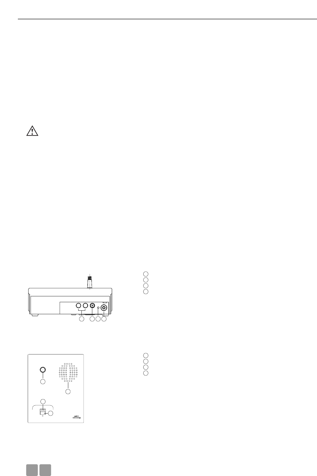
Ladekontakte für Ladegerät CC 10, CD 10
DC-Buchse zum Laden der Sprechstelle und für DC-Betrieb
Betriebskontroll-LED (grün / rot)
Stereo-Klinken-Buchse (3,5 mm) zum Anschluss für Recorder oder
Kopfhörer (z.B. DT 1)
Rückseite
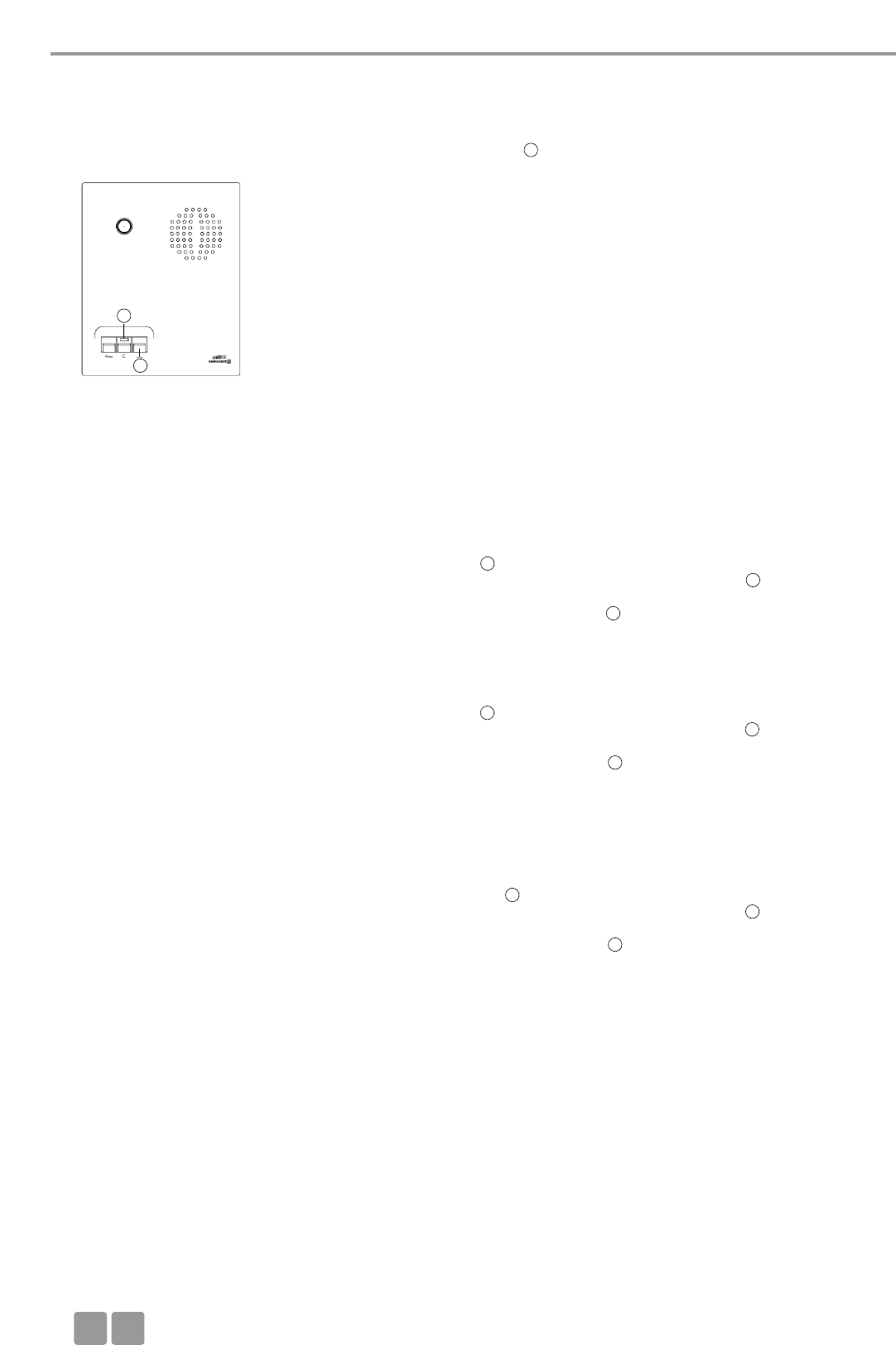
Schwanenhalsmikrofon mit Leuchtring
Lautsprecher
LED zur Funktionsanzeige (grün/rot)
Mikrofontaste
Oberseite Delegierte MCW-D 521
1
1
2
3
4
5
6
7
8
234
5
6
7
8
Sprechstellen
D13
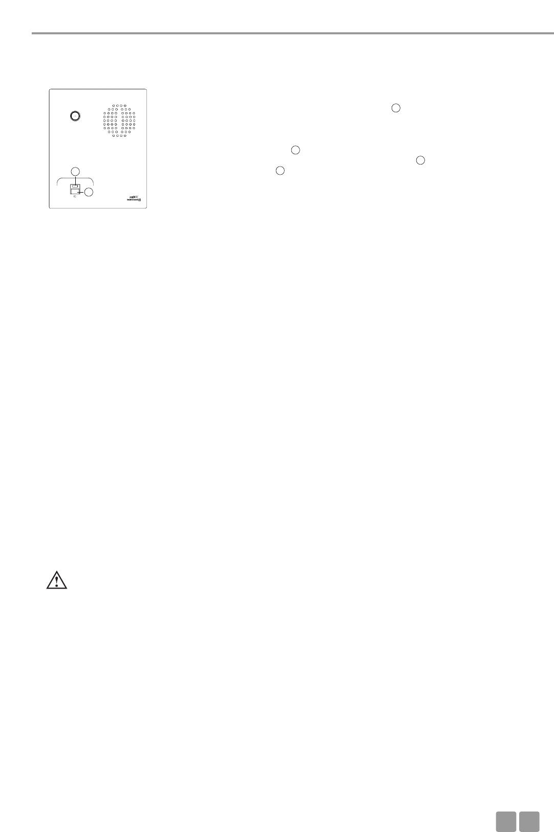
Schwanenhalsmikrofon mit Leuchtring
Lautsprecher
LED zur Funktionsanzeige (grün/rot)
Mikrofontaste
Clear-Taste zum Löschen der Delegierten-Sprechstellen
Programmierbare Funktionstaste (siehe auch Kapitel 6.2)
Oberseite Präsident MCW-D 523
4.1.2 Ein-/Ausschalten
Delegierte Präsident Einschalten
• Die Sprechstellen haben keinen separaten Ein-/Ausschalter. Sie
werden über die Mikrofontaste ein- und ausgeschaltet.
• Durch kurzes Drücken wird die Sprechstelle eingeschaltet. Dabei
leuchtet die LED kurz auf und die grüne Betriebskontroll-LED
auf der Rückseite leuchtet.
Ausschalten
• Durch langes Drücken (> 2 Sek.) wird die Sprechstelle ausgeschal-
tet, wobei die LED zweimal kurz orange blinkt.
• Alle eingeschalteten MCW-D Sprechstellen in „Reichweite“ der
Steuerzentrale MCW-D 50 können auch über die Steuerzentrale
ausgeschaltet werden, wenn Sie den Standby-Taster länger
als 3 Sekunden drücken.
• Außerdem schalten sich die Sprechstellen selbsttätig aus, wenn
sie länger als ca. 3 Minuten kein Signal von der Steuerzentrale
MCW-D 50 mehr empfangen.
Wichtig:
• Befindet sich die Sprechstelle außerhalb der Reichweite
der Steuerzentrale, blinkt die LED immer wieder kurz
rot auf. Nach ca. 3 Minuten schaltet sich die Sprechstelle
dann automatisch ab.
• Sollte das System nicht funktionieren, d.h. die Sprech-
stelle wird eingeschaltet, es ist aber kein Ton zu hören,
drücken Sie auf die Reset-Taste an der Steuerzentrale.
Sollte das System trotzdem nicht funktionieren, prüfen
Sie die Audioeinstellungen mit der MCW-D 50
Conference Software. Funktioniert das System immer
noch nicht, setzen Sie sich bitte mit Ihrer beyerdynamic-
Vertretung in Verbindung.
5
6
6
7
7
7
3
8
9
5
7
89 10
8
8
10
versenkte Reset-Taste
Unterseite MCW-D 521 / MCW-D 523
11
11
8
7
2
2
3
3
Wichtig:
• Mit der MCW-D 50 Conference Software kann das
manuelle Abschalten der Sprechstelle deaktiviert werden.
7 7

Inbetriebnahme
D
14
4.2 Speisung / Betriebszeit
• Die Sprechstellen haben einen integrierten Akku, der vollgeladen eine
Betriebszeit von ca. 20 Stunden gewährleistet.
• Bei nachlassender Spannung, blinkt die Betriebskontroll-LED auf der
Rückseite der Sprechstelle. Die Restbetriebszeit beträgt ca. eine Stunde.
• Die nachlassende Akkuspannung der Sprechstellen kann mit der mitge-
lieferte MCW-D 50 Conference Software auf einen an die Steuerzentrale
MCW-D 50 angeschlossenen PC angezeigt werden. Außerdem ist die
Anzeige auf einer an die MCW-D 50 angeschlossenen externen
Mediensteuerung möglich.
Rückseite Sprechstelle
4.3 Speisung über externes Netzteil CA 2457
• Die MCW-D Sprechstellen können auch über das externe DC-Netzteil
CA 2457 gespeist werden, welches Sie auf der Rückseite der jeweili-
gen Sprechstelle anschließen.
• Während das Netzteil angeschlossen ist, wird die Sprechstelle auch gela-
den. Siehe hierzu auch Kapitel 8. Akkuladung über externes Netzteil.
Rückseite Sprechstelle
4.4.1 Betriebsart Normal
4.4 Betriebsarten
• Die verschiedenen Betriebsarten wie Normal, Push-To-Talk oder Sprachaktiviert werden mit der MCW-D 50 Conference
Software für alle Sprechstellen gemeinsam eingestellt. Die ab Werk eingestellte Betriebsart ist Normal. Siehe hierzu die ent-
sprechende Bedienungsanleitung MCW-D 50 Conference Software.
• Schalten Sie das Schwanenhalsmikrofon mit der Mikrofontaste
ein.
• Roter Leuchtring am
Schwanenhalsmikrofon leuchtet
und LED leuchtet grün: Das Mikrofon ist sprechbereit
• Mit der Steuerzentrale MCW-D 50-3 können 3 Teilnehmer (z.B. 2
Delegierte und 1 Präsident gleichzeitig sprechen. Mit der
Steuerzentrale MCW-D 50-9 können bis zu 9 Teilnehmer (z.B. bis
zu 8 Delegierte und ein Präsident) gleichzeitig sprechen.
Wichtig:
• Sollte die maximale Anzahl der gleichzeitig akti-
vierten Sprechstellen erreicht sein, kann das
Mikrofon erst dann manuell eingeschaltet werden,
wenn eine andere Sprechstelle ausgeschaltet
wurde.
Delegierte Präsident
3
3
2
2
8
7
7
8
8
7
Inbetriebnahme
D15
4.5 Aufzeichnen der Konferenz
• An den Dokumentationsausgang kann ein Recorder (z.B. Notebook
mit steno-s Software) zur Aufzeichnung der Konferenz angeschlossen
werden.
• Die Lautstärke kann über einen PC mit der MCW-D 50 Conference
Software eingestellt werden.
• An den Dokumentationsausgang kann auch ein Kopfhörer ange-
schlossen werden. Wir empfehlen eine Impedanz von 600 Ω. Niedrigere
Impedanzen beschädigen die Sprechstelle zwar nicht, können aber den
Kopfhörerbetrieb beeinträchtigen.
4.6 Pflege der MCW-D Sprechstellen
• Zum Reinigen der MCW-D Sprechstellen bei leichten Verschmutzungen wie Fingerabdrücke, Staub und wasserverdünnbaren
Verschmutzungen (z.B. Fruchtsaft) nehmen Sie ein feuchtes Tuch, Schwamm oder Bürste und einen flüssigen
Haushaltsreiniger.
• Vor der Reinigung muss die Fläche gründlich angefeuchtet werden. Zum Schluss mit einem feuchten Tuch abwischen.
• Achten Sie darauf, dass kein Wasser in die Mikrofonkapsel oder in das Gehäuse läuft.
• Bei Verschmutzungen durch Mineralöle und -fette sowie tierische und pflanzliche Fette können Sie Spiritus, Isopropylalkohol
oder Reinigungsbenzin verwenden.
• Verschmutzungen durch Kugelschreiber, Farbband oder Kohlepapier behandeln Sie am besten mit Isopropylalkohol oder
Spiritus.
• Die Ladekontakte reinigen Sie von Zeit zu Zeit mit Spiritus oder Isopropylalkohol.
• Den Poppschutz reinigen Sie am besten mit klarem, warmen Wasser. Achten Sie darauf, dass der Poppschutz vollkommen
trocken ist, bevor sie ihn wieder auf das Mikrofon aufsetzen.
4.4.2 FIFO-Betrieb
• Arbeiten die Sprechstellen im FIFO-Betrieb, wird die zuerst eingeschaltete Sprechstelle beim Zuschalten einer weiteren
Sprechstelle ausgeschaltet, wenn die Anzahl der maximal offenen Mikrofone (NOM) überschritten wird.
4.4.4 Sprachaktivierter Betrieb
• Arbeiten die Sprechstellen im sprachaktivierten Betrieb, werden die Sprechstellen sprachgesteuert eingeschaltet. Das heißt
sobald in das Mikrofon gesprochen wird, schaltet sich die Sprechstelle ein. Die Mikrofontaste wird in diesem Fall nicht
bedient.
4.4.3 Push-To-Talk-Betrieb
• Arbeiten die Sprechstellen im Push-To-Talk-Betrieb (PTT), muss die Mikrofontaste solange gedrückt werden, wie der Sprecher
ins Mikrofon spricht. Diese Konfiguration empfiehlt sich zum Beispiel dann, wenn kurz in die Konferenz zwischengerufen
werden soll.
Wichtig:
• Die Ansprechschwelle und die Hold-Zeit wird mit der MCW-D 50 Conference Software für alle Sprechstellen gemein-
sam konfiguriert.
4
4
4
5. Programmierbare Sprechstellenfunktionen mit MCW-D 50 Conference Software
Die nachfolgend aufgeführten Sprechstellenfunktionen sind nur dann verfügbar, wenn sie zuvor mit der MCW-D 50 Conference
Software programmiert wurden. Genaue Beschreibung siehe in der entsprechenden Bedienungsanleitung MCW-D 50
Conference Software.
5.1 Sicherheitscode
Mit der MCW-D 50 Conference Software kann den MCW-D Sprechstellen und der Steuerzentrale MCW-D 50 innerhalb eines
Systems ein alphanumerischer Code vergeben werden. Die Abhörsicherheit des Systems wird somit erhöht. Sprechstellen, die
diesen Code nicht besitzen, werden von der Steuerzentrale nicht erkannt und abgeschaltet.
Inbetriebnahme
D
16
5.2 Programmierbare Funktionstaste Präsidentensprechstelle MCW-D 523
Die Funktionstaste hat je nach Konfiguration eine der folgenden
Funktionen: Mute, Löschen oder Priorität. Die Funktionstaste der
Präsidentensprechstelle wird drahtlos über die Steuerzentrale mit der
MCW-D 50 Conference Software konfiguriert werden.
1. Normal
Alle aktiven Delegiertensprechstellen werden gelöscht und das Mikrofon
der Präsidentensprechstelle wird eingeschaltet. Die Delegierten können
ihr Mikrofon erst wieder einschalten, wenn der Prioritätsmodus been-
det wurde.
2. Stummschalten
Alle aktiven Delegiertensprechstellen werden vorübergehend stumm-
geschaltet, wenn der Präsident spricht. Sobald der Präsident den
Prioritätsmodus beendet, werden die vorher aktiven Delegierten-
sprechstellen wieder aktiviert.
3. Löschen
Alle aktiven Delegiertensprechstellen werden gelöscht und können ihr
Mikrofon anschließend wieder einschalten.
4. Stummschalten der AUX-IN-Anschlüsse
Mit dem ersten Drücken der Funktionstaste wird der Anschluss stumm-
geschaltet, beim zweiten Drücken der Funktionstaste wird die Stumm-
schaltung aufgehoben, beim dritten Drücken wird der Anschluss wie-
der stummgeschaltet usw.
Wenn der Präsident die Funktionstaste an seiner Sprechstelle drückt,
wird der Aux-Input an der Steuerzentrale MCW-D 50 stummgeschaltet.
Die LED über der Mikrofontaste blinkt rot (langsam). Wenn der
Präsident sein Mikrofon einschaltet, blinkt die LED grün (langsam).
Wenn die Priorität abgeschaltet wird und das Mikrofon noch einge-
schaltet ist, leuchtet die LED grün.
5. Stummschalten der AUX-IN-Anschlüsse und Löschen aller aktiven
Delegiertensprechstellen. Beim zweiten Drücken der Funktionstaste
wird die Stummschaltung aufgehoben, beim dritten Drücken wird der
Anschluss wieder stummgeschaltet und alle aktiven Delegiertensprech-
stellen gelöscht usw.
Die LED über der Mikrofontaste blinkt rot (langsam). Wenn der
Präsident sein Mikrofon einschaltet, blinkt die LED grün (langsam).
Wenn die Priorität abgeschaltet wird und das Mikrofon noch einge-
schaltet ist, leuchtet die LED grün.
6. Stummschalten der AUX-OUT-Anschlüsse
Mit dem ersten Drücken der Funktionstaste wird der Anschluss stumm-
geschaltet, beim zweiten Drücken der Funktionstaste wird die Stumm-
schaltung aufgehoben, beim dritten Drücken wird der Anschluss wie-
der stummgeschaltet usw.
Wenn der Präsident die Funktionstaste an seiner Sprechstelle drückt,
wird der Aux-Output an der Steuerzentrale MCW-D 50 stummgeschal-
tet. Die LED über der Mikrofontaste blinkt rot (langsam). Wenn der
Präsident sein Mikrofon einschaltet, blinkt die LED grün (langsam).
Wenn die Priorität abgeschaltet wird und das Mikrofon noch einge-
schaltet ist, leuchtet die LED grün.
7. Funktion „RS 232 Nachricht“
Über die RS 232 Schnittstelle wird von der Steuerzentrale MCW-D 50 ein
Befehl gesendet, der z.B. in Verbindung mit einer Mediensteuerung
eine programmierte Funktion ausführt (z.B. Licht ein/aus).
Gleichzeitig wird auch bei den anderen Funktionen ein Befehl über die
RS 232 Schnittstelle von der Steuerzentrale MCW-D 50 gesendet.
8. Befehl A/B
Zwei verschiedene Befehle je nachdem wie lange die Funktionstaste
gedrückt wird
< 1 Sekunde = Befehl „Short press string“ wird übertragen
> 1 Sekunde = Befehl „Long press string“ wird übertragen
Diese Befehle können mit der MCW-D 50 Conference Software kun-
denspezifisch eingestellt werden.
Sprechstelle
10
10
7
7
7
7
7
7
7
7
7
7
Inbetriebnahme
D17
6. Ladegerät CD 10 im Koffer CC 10
• Mit dem im Transportkoffer CC 10 integrierten Ladegerät CD 10 können bis zu 10 Sprechstellen gleichzeitig geladen werden.
Der Ladezustand ist über das Sichtfenster von außen einsehbar.
• Der Transportkoffer CC 10 kann jederzeit um weitere Ladeeinheiten CD 10 für jeweils 10 Sprechstellen erweitert werden.
Das Ladegerät CD 10 verfügt über ein Aufbewahrungsfach für Zubehör wie z.B. Kopfhörer.
6.1 Erstinbetriebnahme
• Alle Sprechstellen sollten mindestens 2 komplette Ladezyklen durchlaufen (laden und entladen), damit eine 100%ige
Betriebskapazität der Akkus in den Sprechstellen gewährleistet ist. Ein Akku erreicht erst nach mehrmaligem Auf- und
Entladen seine volle Kapazität.
5.3 Betriebsart Anmeldung
• Diese Betriebsart funktioniert nur in Verbindung mit einem Bedien-PC
und der MCW-D 50 Conference Software oder einem
Mediensteuersystem (AMX®, Crestron®, Cue etc.).
• Durch Drücken der Mikrofontaste an der Sprechstelle wird eine
Anmeldung im System registriert.
• Die Zuteilung erfolgt durch den Bediener am PC oder Touchscreen der
Mediensteuerung.
• Die LED leuchtet rot, um die Anmeldung zu signalisieren.
• Ein erneutes Drücken der Mikrofontaste löscht die Anmeldung. Die
LED geht aus.
Delegierter
6.2 Ladevorgang
1. Schließen Sie das Ladegerät ans Netz an und schalten Sie es mit dem Ein-/Ausschalter ein. Der Schalter leuchtet.
2. Schieben Sie die ausgeschalteten Sprechstellen in die Ladefächer. Eventuell noch eingeschaltete Sprechstellen werden auto-
matisch ausgeschaltet. Werden die Sprechstellen wieder dem Ladefach entnommen, müssen sie von Hand eingeschaltet
werden.
3. Der Ladevorgang wird durch den LED-Ring am Schwanenhals angezeigt und ist von außen durch ein Sichtfenster einsehbar.
LED-Anzeige bei Ladevorgang des Akkus:
a) Schwanenhals-LED blinkt rot . . . . . . . . . . . . . . . . . Akku wird geladen
b) Schwanenhals-LED leuchtet dauerhaft rot . . . . . . Akku voll
c) Schwanenhals-LED blinkt schnell rot . . . . . . . . . . . Fehlermeldung
Hinweis:
• Liegt eine Fehlermeldung vor, versuchen Sie den Ladevorgang noch einmal durchzuführen. Sollten die LEDs noch
immer schnell blinken, setzen Sie sich bitte mit Ihrer beyerdynamic-Vertretung in Verbindung.
• Die Ladedauer beträgt bei vollständig entleertem Akku max. 2 Stunden.
• Nach einiger Zeit verlieren Akkus technisch bedingt an Kapazität. Dadurch verkürzt sich die Betriebszeit.
• Es ist normal, dass sich Akkus während des Ladevorgangs etwas aufheizen.
• Zum Reinigen der Ladekontakte verwenden Sie Spiritus oder Isopropylalkohol.
7
8
8
7
7
8

Problemlösung
D
18
7. Akkuladung über externes Netzteil
• Die MCW-D Sprechstellen können auch über das externe Netzteil
CA 2457 geladen werden, welches Sie an die DC-Buchse anschließen.
• Der Ladevorgang wird durch die Betriebskontroll-LED angezeigt.
LED-Anzeige bei Ladevorgang des Akkus:
a) LED blinkt rot . . . . . . . . . . . . . . . . . . . . . . . . Akku wird geladen
b) LED leuchtet dauerhaft rot . . . . . . . . . . . . . Akku voll
c) LED blinkt schnell rot . . . . . . . . . . . . . . . . . . Fehlermeldung
Rückseite
Wichtig:
• Nach einiger Zeit verlieren Akkus technisch bedingt an
Kapazität. Dadurch verkürzt sich die Betriebszeit.
• Es ist normal, dass sich Akkus während des Ladevorgangs etwas
erwärmen.
• Die Ladedauer beträgt bei vollständig entleertem Akku und
Langsamladung ca. 5 Stunden.
• Wird die Sprechstelle während des Ladevorgangs eingeschaltet,
leuchtet die LED grün.
8. Problemlösung
Bei auftretenden Problemen mit den Sprechstellen, die nicht in der unten aufgeführten Auflistung stehen, sollte das MCW-D 50
System mit Hilfe der MCW-D 50 Conference Software zunächst wieder auf die Standardkonfiguration eingestellt werden. Siehe
hierzu die entsprechende Bedienungsanleitung.
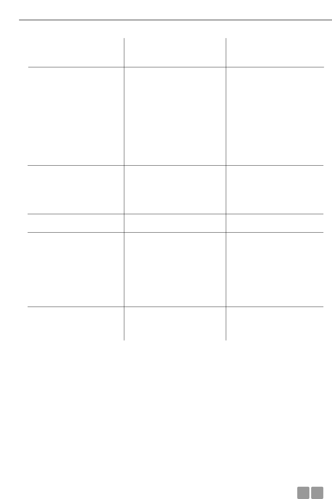
Problem
LED der Mikrofontaste blinkt schnell rot
Betriebskontroll-LED blinkt
Sprechstelle geht aus
Zuteilung nicht möglich
Sprechstelle lässt sich nicht einschalten
Mögliche Ursache
• Steuerzentrale ist nicht eingeschaltet
• Reichweite ist überschritten
• Frequenzbänder falsch konfiguriert
• Akku ist fast leer
• Akkurestzeitwarnschwelle zeigt an,
dass der Akku bald leer ist
• Überprüfen Sie den Akku, ob er
noch voll ist
• Verschlüsselungscode ist aktiviert
• Alle Kanäle belegt
• Überprüfen Sie die NOM Einstellung
in der MCW-D 50 Conference
Software
• Reichweite ist überschritten
• Überprüfen Sie die Einstellungen der
Frequenzbänder
• Störung durch WLAN
• Steuerzentrale ist nicht eingeschaltet
• Überprüfen Sie die NOM-Einstellung
• Überprüfen Sie den Akku
• Reichweite ist überschritten
Lösung
• Schalten Sie die Steuerzentrale ein
• Verringern Sie den Abstand zwischen
Steuerzentrale und Sprechstellen
• Überprüfen Sie die Einstellungen der
Frequenzbänder mit der MCW-D 50
Conference Software
• Laden Sie die Sprechstelle wieder
auf
• Falls der Akku leer ist, laden Sie die
Sprechstelle wieder auf
• Verschlüsselungscode deaktivieren
• Schalten Sie ein aktives Mikrofon aus
• Wenn möglich erhöhen Sie die NOM
in der MCW-D Conference Software
• Verringern Sie den Abstand zwischen
Steuerzentrale und Sprechstellen
• Verwenden Sie die in der
Bedienungsanleitung MCW-D 50
Conference Software genannten
Standardeinstellungen.
• Wählen Sie mit der MCW-D 50
Conference Software ein anderes
Frequenzband für das/die HF-
Modul/e
• Schalten Sie die Steuerzentrale ein
• Wenn möglich erhöhen Sie die NOM
• Falls der Akku leer ist, laden Sie die
Sprechstelle wieder auf
• Verringern Sie den Abstand zwischen
Steuerzentrale und Sprechstellen
2
2
3
3
3
Problemlösung
D19
Mögliche Ursache
• Überprüfen Sie die Lautstärke-
einstellung mit der MCW-D
Conference Software
• Manuelles Abschalten ist deaktiviert.
• Betriebsart Push-To-Talk oder
Sprachaktiviert ist aktiviert
• Microcontroller in der Sprechstelle
ist abgestürzt
• Sprechstelle ist nicht eingeschaltet
• Kopfhörer ist nicht richtig ange-
schlossen
• Überprüfen Sie die Lautstärke-
einstellung mit der MCW-D
Conference Software
• Überprüfen Sie die externen
Lautsprecher
• Überprüfen Sie den Audiopegel
• Reichweite ist überschritten
• Überprüfen Sie die Antennen-
position und Antennenkabel
• Überprüfen Sie die Sichtverbindung
zwischen Sprechstelle und Antenne
• Störungen durch Geräte wie
Wireless LAN
Lösung
• Erhöhen Sie die Lautstärke über die
MCW-D Conference Software oder
mit dem Volume-Regler an der
Steuerzentrale
• Aktivieren Sie die Funktion
„Manuelles Abschalten“ mit der
MCW-D 50 Conference Software
• Deaktivieren Sie die Betriebsart
Push-To-Talk oder Sprachaktiviert in
der MCW-50 Conference Software
• Schalten Sie die Sprechstellen über
die Steuerzentrale aus, indem Sie die
Clear/Standby-Taste länger als 3
Sekunden drücken
• Schalten Sie die Steuerzentrale aus,
nach ca. 3 Minuten gehen die
Sprechstellen aus
• Drücken Sie auf die versenkte Reset-
Taste auf der Sprechstellenunterseite
• Schalten Sie die Sprechstelle ein
• Schließen Sie den Kopfhörer richtig
an
• Erhöhen Sie die Lautstärke über die
MCW-D Conference Software bzw.
mit dem Lautstärkeregler an der
MCW-D 50 Steuerzentrale
• Korrigieren Sie die Lautstärke und
Position der Lautsprecher
• Verringern Sie den Eingangspegel an
der Steuerzentrale
• Verringern Sie den Abstand zwischen
Steuerzentrale und Sprechstellen
• Unter Umständen sollte ein
Antennensignalverstärker eingesetzt
werden
• Hindernisse zwischen Sprechstellen
und Antennen beseitigen; vor die
Antennen der Steuerzentrale darf
nichts gestellt werden
• Wählen Sie mit der MCW-D 50
Conference Software ein anderes
Frequenzband für das/die HF-
Modul/e. Siehe auch Kapitel 8.1.
Problem
Sprechstellenlautsprecher funktioniert
nicht
Sprechstelle lässt sich nicht ausschalten
Dokumentationsausgang funktioniert
nicht
Rückkopplungen
Störgeräusche
Kurze Aussetzer
8.1 Gleichzeitiger Betrieb des MCW-D Konferenzsystems mit anderen 2,4 GHz Geräten
(z.B. WLAN, Bluetooth)
8.1.1 Physikalische Grundlagen
Aufgrund physikalischer Gesetzmäßigkeiten kann ein gleichzeitiger, störungsfreier Betrieb verschiedener Geräte, die dasselbe
Frequenzband nutzen, nicht garantiert werden. Funkgeräte auf demselben Frequenzband werden sich immer gegenseitig
beeinflussen und stören (ggf. führt dies auch zu Funktionsbeeinträchtigungen).
Dies wird deutlich am Beispiel von UHF-Funkstrecken wie z.B. Drahtlosmikrofonen. Hier ist bekannt, dass niemals 2 Funk-
strecken gleichzeitig mit derselben Trägerfrequenz betrieben werden können. Stand der Technik ist, dass innerhalb eines
bestimmten Frequenzbereichs nur eine bestimmte Anzahl kompatibler Funkstrecken betrieben werden kann.
Dieselben Gesetzmäßigkeiten gelten für das 2,4 GHz-ISM Band (2400 MHz - 2484 MHz). Aufgrund digitaler Übertragungsver-
fahren und verschiedener Übertragungsstandards ist hier zwar ein gleichzeitiger Betrieb bestimmter Geräte auf demselben
Frequenzband eingeschränkt möglich, aber nicht empfehlenswert.
Problemlösung
D
20
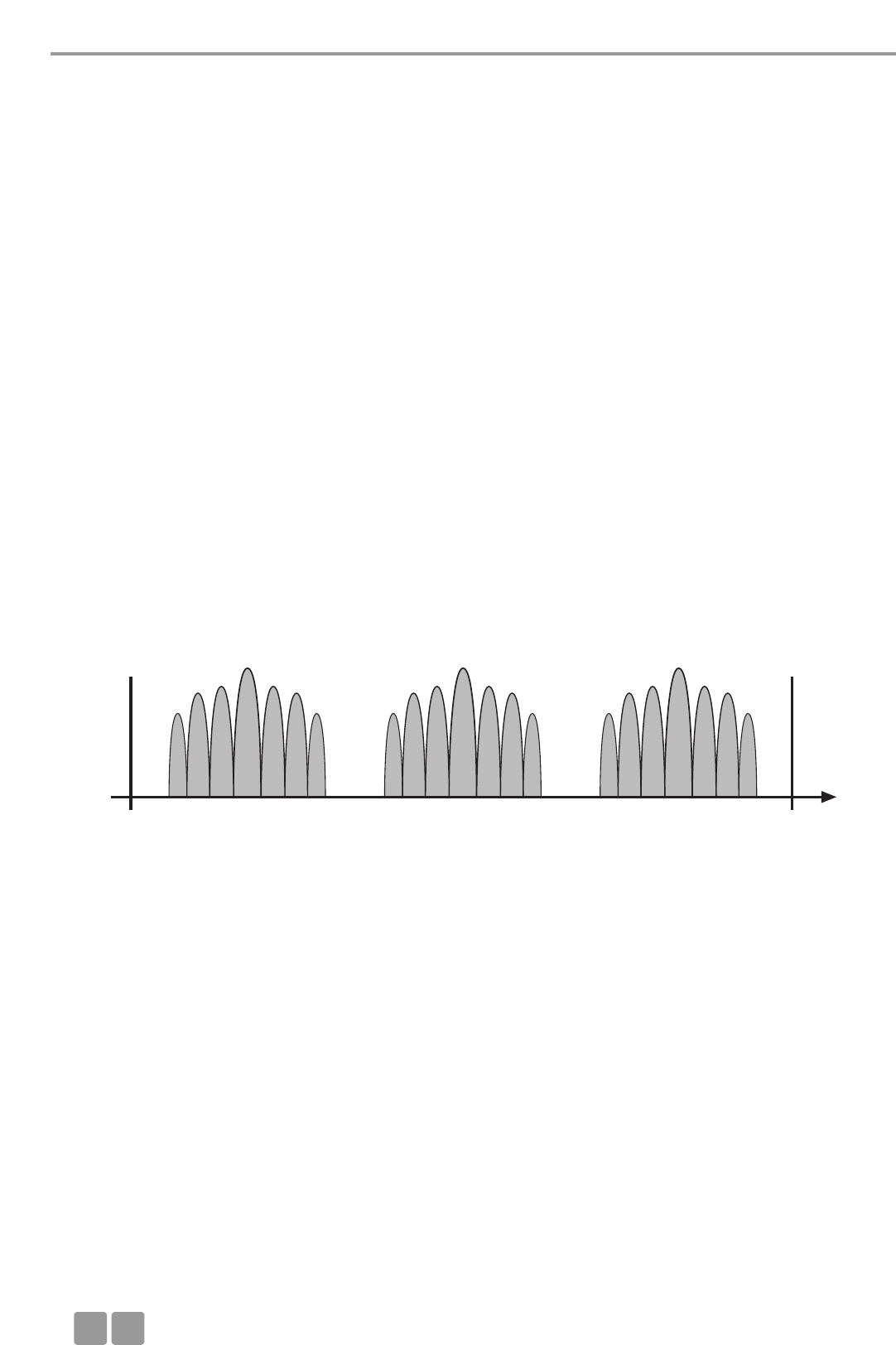
Übersicht Frequenznutzung MCW-D 50 / WLAN
MCW-D 50 WLAN
Kanal. . . . . . . . . . . . . . . . . . . Mittenfrequenz Kanal . . . . . . . . . . . . . . . . . . Mittenfrequenz
Low . . . . . . . . . . . . . . . . . . . . 2412 MHz 1 . . . . . . . . . . . . . . . . . . . . . . . 2412
2 . . . . . . . . . . . . . . . . . . . . . . . 2417
3 . . . . . . . . . . . . . . . . . . . . . . . 2422
4 . . . . . . . . . . . . . . . . . . . . . . . 2427
5 . . . . . . . . . . . . . . . . . . . . . . . 2432
Mid. . . . . . . . . . . . . . . . . . . . . 2438 MHz 6 . . . . . . . . . . . . . . . . . . . . . . . 2437
7 . . . . . . . . . . . . . . . . . . . . . . . 2442
8 . . . . . . . . . . . . . . . . . . . . . . . 2447
9 . . . . . . . . . . . . . . . . . . . . . . . 2452
10 . . . . . . . . . . . . . . . . . . . . . . 2457
High . . . . . . . . . . . . . . . . . . . . 2464 MHz 11 . . . . . . . . . . . . . . . . . . . . . . 2462
12 . . . . . . . . . . . . . . . . . . . . . . 2467
13 . . . . . . . . . . . . . . . . . . . . . . 2472
14 . . . . . . . . . . . . . . . . . . . . . . 2484
Man kann leicht erkennen, dass sich die einzelnen WLAN Kanäle aufgrund ihrer Bandbreite stark überschneiden. Alle benach-
barten Kanäle (z.B. Kanal 1 & 2 oder Kanal 7 & 8) sind nicht parallel nutzbar, da sie sich gegenseitig stören würden. Darüber
hinaus ist zu berücksichtigen, dass in den USA die Kanäle 12 und 13 nicht zugelassen sind. Diese Kanäle werden daher in der
Praxis im allgemeinen nicht verwendet. Innerhalb des verbleibenden Frequenzbands sind somit nur die WLAN-Kanäle 1, 6 und
11 überlappungsfrei und damit parallel nutzbar. Diese Kanalnutzung hat sich in der Praxis etabliert.
Aus diesem Grund wurden für die vom MCW-D 50 Konferenzsystem verwendeten HF-Kanäle Low, Mid und High entsprechend
die WLAN-Kanäle 1, 6 und 11 gewählt. Dank dieser frequenztechnischen Kompatibilität arbeitet das Konferenzsystem WLAN-
freundlich.
Durch sorgfältige Frequenzplanung und Einhaltung der Frequenzdisziplin ist es möglich eine MCW-D 50-3 Steuerzentrale mit
mehr als 4000 Sprechstellen sowie bis zu zwei WLAN-Strecken in unmittelbarer Nähe parallel zu betreiben.
Weitere Tipps zur Installation
• Zwischen Geräten mit WLAN oder WiFi (z.B. Router, Repeater) und den Sende- und Empfangsantennen der Steuerzentrale
MCW-D 50 sollte ein Mindestabstand von ca. 5 m eingehalten werden.
• An Notebooks sollten nach Möglichkeit alle WLAN-Schnittstellen, die denselben Frequenzbereich wie MCW-D 50 nutzen,
deaktiviert werden.
• Grundsätzlich empfiehlt es sich, dass die für WLAN- bzw. WiFi-Datenverkehr sowie die für MCW-D 50 genutzten HF-Kanäle
möglichst weit auseinander liegen.
• Die zu nutzenden Kanäle des MCW-D 50 Konferenzsystems lassen sich problemlos über die im Lieferumfang enthaltene
MCW-D 50 Konferenzsoftware einstellen.
2400 MHz Low Mid High 2484 MHz
Frequenz /
MHz
8.1.2 MCW-D und WLAN bzw. WiFi
Die HF-Übertragung des MCW-D 50 Systems orientiert sich am WLAN-Standard, d.h. MCW-D 50 nutzt, wie WLAN, eine
Bandbreite von ca. 22 MHz für jeden HF-Kanal (Low, Mid, High). Unter Berücksichtigung einer in der Realität nicht möglichen
idealen Kanaltrennung, ergibt dies für beide Technologien drei nicht überlappende, kompatible HF-Kanäle im 2,4 GHz-ISM
Band. Diese sind theoretisch:
Kompatibler Kanal 1: 2400 MHz - 2428 MHz (theoret. Mittenfrequenz 2414 MHz)
Kompatibler Kanal 2: 2428 MHz - 2456 MHz (theoret. Mittenfrequenz 2442 MHz)
Kompatibler Kanal 3: 2456 MHz - 2484 MHz (theoret. Mittenfrequenz 2470 MHz)
Das MCW-D 50 System nutzt mit den einstellbaren HF-Kanälen Low, Mid und High ausschließlich zueinander kompatible, über-
lappungsfreie Frequenzbereiche. Bei WLAN ist es den Benutzern selbst überlassen, zueinander kompatible HF-Kanäle zu konfi-
gurieren.

Zubehör
D21
8.1.3 MCW-D 50 und Bluetooth
• Im Gegensatz zu WLAN und MCW-D 50 nutzen Geräte mit Bluetooth-Übertragung das gesamte 2,4 GHz-ISM Band durch eine
ständig wechselnde Trägerfrequenz („Frequency Hopping“).
• Durch verschiedene konstruktive Maßnahmen im MCW-D 50 System sowie ein fortgeschrittenes Übertragungsprotokoll sind
Störeinflüsse durch Bluetooth-Geräte (auch Mikrowellenherde) im Normalbetrieb weitgehend auszuschließen.
• Es ist jedoch nicht auszuschließen, dass vorhandener Bluetooth-Datenverkehr durch MCW-D 50 beeinträchtigt wird.
8.1.4 Anwendungsbeispiel: MCW-D 50, Mediensteuerung und WLAN
In der Konferenztechnik ist die Nutzung von 2,4 GHz-Technologie für verschiedene Anwendungen weit verbreitet. Neben einem
drahtlosen Konferenzsystem sollen häufig weitere Abläufe bedient werden (Licht-, Lautstärkeregelung etc.) z.B. durch ein
drahtloses 2,4 GHz-Touchpanel in Verbindung mit einer Mediensteuerung. Außerdem ist es vielfach üblich
Konferenzteilnehmern über einen WLAN-Access-Point einen direkten Internetzugriff zu ermöglichen.
Mit dem MCW-D 50 Konferenzsystem und WLAN haben Sie bereits Komponenten im Einsatz, die zueinander kompatible Über-
tragungsstandards nutzen. Dies sollte auch bei der Auswahl der Mediensteuerung mit Touchpanel beachtet werden. Moderne
Geräte orientieren sich zunehmend am WLAN-Standard.
1. Konfigurieren Sie das Konferenzsystem MCW-D 50-3 auf den HF-Kanal Low. MCW-D 50 nutzt so den Frequenzbereich von ca.
2401 - 2423 MHz. Dieser Frequenzbereich muss ausschließlich für die Nutzung durch MCW-D 50 reserviert bleiben.
2. Konfigurieren Sie das Touchpanel der Mediensteuerung auf den Frequenzbereich von ca. 2426 - 2448 MHz. Dies entspricht
WLAN-Kanal 6. Dieser Frequenzbereich muss ausschließlich für die Nutzung durch das Touchpanel reserviert bleiben.
3. Konfigurieren Sie den WLAN-Access-Point auf WLAN-Kanal 11. Dieser nutzt den Frequenzbereich von ca. 2451 - 2473 MHz.
Dieser Frequenzbereich muss ausschließlich für die Nutzung durch WLAN reserviert bleiben.
9. Komponenten
MCW-D 50-3 Steuerzentrale mit 1 HF-Modul mit 3 Kanälen. . . . . . . . . . . . . . . . . . . . . . . . . . . . . . Best.-Nr. 479.705
MCW-D 50-9 Steuerzentrale mit 3 HF-Module mit 9 Kanälen . . . . . . . . . . . . . . . . . . . . . . . . . . . . . Best.-Nr. 481.560
MCW-D 521 Delegiertensprechstelle mit Lautsprecher. . . . . . . . . . . . . . . . . . . . . . . . . . . . . . . . . . Best.-Nr. 479.748
MCW-D 523 Präsidentensprechstelle mit Lautsprecher. . . . . . . . . . . . . . . . . . . . . . . . . . . . . . . . . . Best.-Nr. 479.756
CC 10 Ladekoffer für 10 MCW-D 5**-Sprechstellen,
bestehend aus Deckel CT 10, Ladeetage CD 10, Rollenboden CW 10 . . . . . . . . . . . . Best.-Nr. 479.764
CD 10 Ladeetage für bis zu 10 MCW-D 5**-Sprechstellen . . . . . . . . . . . . . . . . . . . . . . . . . . Best.-Nr. 479.772
CM 10 19"-Etage für Steuerzentrale MCW-D 50 . . . . . . . . . . . . . . . . . . . . . . . . . . . . . . . . . . Best.-Nr. 479.780
CS 10 Leerfach für Steuerzentrale MCW-D 50 . . . . . . . . . . . . . . . . . . . . . . . . . . . . . . . . . . . Best.-Nr. 479.810
CT 10 Deckel . . . . . . . . . . . . . . . . . . . . . . . . . . . . . . . . . . . . . . . . . . . . . . . . . . . . . . . . . . . . . Best.-Nr. 479.799
CW 10 Bodenplatte mit Rollen. . . . . . . . . . . . . . . . . . . . . . . . . . . . . . . . . . . . . . . . . . . . . . . . Best.-Nr. 479.802
10. Zubehör
Lieferumfang
1 Netzkabel
1 serielles Nullmodemkabel
MCW-D 50 Conference Software, inkl. Basisversion Controller für max. 5 Sprechstellen. . . . . . . Best.-Nr. 480.274
Hinweis:
Die Antennen sind nicht im Lieferumfang enthalten.
Optional
CA 2411 Stab-Winkel-Antenne, 2,4 GHz, N-Anschluss . . . . . . . . . . . . . . . . . . . . . . . . . . . . . . . Best.-Nr. 464.236
CA 2412 Stab-Antenne, 2,4 GHz, SMA-Anschluss . . . . . . . . . . . . . . . . . . . . . . . . . . . . . . . . . . . Best.-Nr. 464.244
CA 2413 Planar-Antenne, 2,4 GHz, SMA-Anschluss. . . . . . . . . . . . . . . . . . . . . . . . . . . . . . . . . . Best.-Nr. 464.252
CA 2420 Standardkabel, 2,4 GHz, Meterware, N-Anschluss . . . . . . . . . . . . . . . . . . . . . . . . . . . Best.-Nr. 464.260
CA 2421 Standardkabel, 2,4 GHz, N(HF)-N(HF), 10 m . . . . . . . . . . . . . . . . . . . . . . . . . . . . . . . . Best.-Nr. 464.279
CA 2422 Standardkabel, 2,4 GHz, N(HF-N(HF), 20 m. . . . . . . . . . . . . . . . . . . . . . . . . . . . . . . . . Best.-Nr. 464.287
CA 2430 Dämpfungsarmes Kabel, 2,4 GHz, Meterware . . . . . . . . . . . . . . . . . . . . . . . . . . . . . . Best.-Nr. 464.295
CA 2431 Dämpfungsarmes Kabel, 2,4 GHz, N(HF)-N(HF), 10 m. . . . . . . . . . . . . . . . . . . . . . . . . Best.-Nr. 464.309
CA 2432 Dämpfungsarmes Kabel, 2,4 GHz, N(HF)-N(HF), 20 m. . . . . . . . . . . . . . . . . . . . . . . . . Best.-Nr. 464.325
CA 2441 RT Antennen-Verstärker für Sende- und Empfangsweg, max. 6 dBm Eingangspegel
(10 dB Verstärkung), Fernspeisung 5 V über Antennenkabel. . . . . . . . . . . . . . . . . . . Best.-Nr. 470.309
CA 2441 T Antennen-Verstärker für Sendeweg, max. 20 dBm Eingangspegel
(8 dB Verstärkung), Fernspeisung 5 V über Antennenkabel. . . . . . . . . . . . . . . . . . . . Best.-Nr. 470.317
CA 2442 Adapter N(HF) Female - SMA Male. . . . . . . . . . . . . . . . . . . . . . . . . . . . . . . . . . . . . . . Best.-Nr. 464.376
CA 2443 Adapter N(HF) Female - SMA Female . . . . . . . . . . . . . . . . . . . . . . . . . . . . . . . . . . . . . Best.-Nr. 464.384

Technische Daten
D
22
CA 2444 Adapter N(HF) Male - SMA Female. . . . . . . . . . . . . . . . . . . . . . . . . . . . . . . . . . . . . . . Best.-Nr. 464.392
CA 2445 Adapter N(HF) Male - SMA Male . . . . . . . . . . . . . . . . . . . . . . . . . . . . . . . . . . . . . . . . Best.-Nr. 465.151
CA 2457 Lade-Netzteil mit Ladefunktion und DC-Stecker für MCW-D 5**-Sprechstellen . . . . Best.-Nr. 479.721
MCW-D 50 Controller
Lizenz für Vollversion des Controllers zur Steuerung des Systems über PC . . . . . . . . Best.-Nr. 480.262
11. Technische Daten
Allgemein
Frequenzbereich. . . . . . . . . . . . . . . . . . . . . . . . . . . . . . . . 2400 - 2483,5 MHz (ISM-Band)
Modulationsart. . . . . . . . . . . . . . . . . . . . . . . . . . . . . . . . . Direct Sequence Spread Spectrum DSSS, digitale Signalbearbeitung
nach eigenem Standard
Max. Anzahl der Audiokanäle . . . . . . . . . . . . . . . . . . . . . 9 nutzbare Duplexkanäle pro System
Signal-/Rauschverhalten . . . . . . . . . . . . . . . . . . . . . . . . . . 80 dB typ., unbewertet (Fremdspannung)
Reichweite zwischen Sprechstelle und Zentrale. . . . . . . . > 100 m bei Sichtverbindung
Netzspannung . . . . . . . . . . . . . . . . . . . . . . . . . . . . . . . . . 100 - 240 V AC 50/60 Hz
Zulassung . . . . . . . . . . . . . . . . . . . . . . . . . . . . . . . . . . . . . weltweit zulassungsfreier Betrieb
Sprechstellen
Sendeleistung . . . . . . . . . . . . . . . . . . . . . . . . . . . . . . . . . . max. 100 mW je Kanal (16 dBm)*
Akkuspannung . . . . . . . . . . . . . . . . . . . . . . . . . . . . . . . . . 8 Zellen NiMH mit je 1600 mAh
Externer DC-Betrieb . . . . . . . . . . . . . . . . . . . . . . . . . . . . . 18 V DC (±0,5 V), Restwelligkeit < 20 mV, 400 mA
Lautsprechersystem . . . . . . . . . . . . . . . . . . . . . . . . . . . . . Breitbandiger, eingebauter Lautsprecher, sprachentzerrt
Lautstärkeabsenkung bei Mic On („Ducking“) . . . . . . . . 15 dB fest eingestellt
NF Output . . . . . . . . . . . . . . . . . . . . . . . . . . . . . . . . . . . . . . . Dokumentationsausgang, nicht separat einstellbar, unsymm.
Klinkenbuchse (3,5 mm Stereo)
Belegung . . . . . . . . . . . . . . . . . . . . . . . . . . . . . . . . . . . . . Spitze = NF+
Ring = NF-
Schirm = Gerätemasse
Ausgangspegel . . . . . . . . . . . . . . . . . . . . . . . . . . . . . . . . . max. 2,4 V rms im Leerlauf, Klirrfaktor < 1%
2,3 V rms an 600 ΩLast, Klirrfaktor < 1%
Mindestanschlussimpedanz . . . . . . . . . . . . . . . . . . . . . . . 600 Ω
Eingebauter Limiter gegen Übersteuerung . . . . . . . . . . . nicht abschaltbar
Limitereinsatz bei . . . . . . . . . . . . . . . . . . . . . . . . . . . . . . . 126 dB SPL
Stromversorgung . . . . . . . . . . . . . . . . . . . . . . . . . . . . . . . 9,6 V über eingebauten NiMH-Akku (8 Zellen)
Betriebszeit je nach Sprechstellentyp. . . . . . . . . . . . . . . . ca. 20 Stunden bei Konferenzbetrieb; je nach Abhörlautstärke kann
die Betriebszeit schwanken
Temperaturbereich . . . . . . . . . . . . . . . . . . . . . . . . . . . . . . +10° - +40°C (bei <90% Luftfeuchtigkeit)
Lagertemperatur . . . . . . . . . . . . . . . . . . . . . . . . . . . . . . . -20° - +55°C (bei <90% Luftfeuchtigkeit)
Abmessungen (ohne Mikrofon) . . . . . . . . . . . . . . . . . . . . Länge: 191 mm
Breite: 156,5 mm
Höhe: 52 mm
Gewicht . . . . . . . . . . . . . . . . . . . . . . . . . . . . . . . . . . . . . . 1,7 kg
Steuerzentrale MCW-D 50
Frequenzgang. . . . . . . . . . . . . . . . . . . . . . . . . . . . . . . . . . 70 Hz - 10 kHz (-3 dB)
Betriebsart . . . . . . . . . . . . . . . . . . . . . . . . . . . . . . . . . . . . Antennen-Diversity auf der Empfangsseite, getrennt für jeden Kanal
Antennenanschluss. . . . . . . . . . . . . . . . . . . . . . . . . . . . . . 3 Stück N-Steckverbinder (female)
Fernspeisespannung für Antennensignalverstärker . . . . . 5 V, max. 2 A
Sendeleistung . . . . . . . . . . . . . . . . . . . . . . . . . . . . . . . . . . max. 100 mW je Kanal (16 dBm)*
Anschlüsse
Serieller Steuerport . . . . . . . . . . . . . . . . . . . . . . . . . . . . . RS 232
Ethernet Port . . . . . . . . . . . . . . . . . . . . . . . . . . . . . . . . . . LAN, TCP/IP-Standard
Summenausgang symm. . . . . . . . . . . . . . . . . . . . . . . . . . . XLR, +6 dBu
Summenausgang unsymm.. . . . . . . . . . . . . . . . . . . . . . . . Cinch, Pegel regelbar (1,55 V - 300 mV Regelbereich)
Eingang symm. . . . . . . . . . . . . . . . . . . . . . . . . . . . . . . . . . XLR, +6 dBu, schaltbar
Eingang unsymm. . . . . . . . . . . . . . . . . . . . . . . . . . . . . . . . Cinch (min. 500 mV für Vollaussteuerung),
+15 dBu, -10 dBu, schaltbar
Netzspannung . . . . . . . . . . . . . . . . . . . . . . . . . . . . . . . . . 100 - 240 V AC 50/60 Hz
Netzsicherung. . . . . . . . . . . . . . . . . . . . . . . . . . . . . . . . . . 2 x 3,15 A (träge)
Leistungsaufnahme . . . . . . . . . . . . . . . . . . . . . . . . . . . . . 20 W (ohne angeschlossene Antennensignalverstärker)
Temperaturbereich . . . . . . . . . . . . . . . . . . . . . . . . . . . . . . +10° - +50°C (bei < 90% Luftfeuchtigkeit)
Anzeige . . . . . . . . . . . . . . . . . . . . . . . . . . . . . . . . . . . . . . 9 Kanal-LEDs (rot/grün) und Power-LED (rot/grün)
Min. Rackeinbautiefe . . . . . . . . . . . . . . . . . . . . . . . . . . . . 380 mm
Abmessungen (B x H x T) . . . . . . . . . . . . . . . . . . . . . . . . . 19", 2 HE (440 x 88 x 310 mm)
Gewicht . . . . . . . . . . . . . . . . . . . . . . . . . . . . . . . . . . . . . . 4,7 kg
*Aufgrund länderspezifischer Vorschriften kann die Sendeleistung von diesem Wert abweichen.

Technische Daten
D23
Ladegerät CD 10
Stromversorgung . . . . . . . . . . . . . . . . . . . . . . . . . . . . . . . 100 - 240 V AC~, 50/60 Hz
Sicherung an Netzbuchse . . . . . . . . . . . . . . . . . . . . . . . . . 2 x 6,3 A (träge)
Leistungsaufnahme . . . . . . . . . . . . . . . . . . . . . . . . . . . . . max. 150 W
Max. Umgebungstemperatur . . . . . . . . . . . . . . . . . . . . . . +10° - +40°C im Ladebetrieb (< 90% Luftfeuchtigkeit)
Lagertemperatur . . . . . . . . . . . . . . . . . . . . . . . . . . . . . . . -20° - +55°C
Ladeeinheit. . . . . . . . . . . . . . . . . . . . . . . . . . . . . . . . . . . . 10 Sprechstellen parallel
Ladedauer. . . . . . . . . . . . . . . . . . . . . . . . . . . . . . . . . . . . . max. 2 Stunden bei vollständig leerem Akku
Abmessungen (L x B x H) . . . . . . . . . . . . . . . . . . . . . . . . . 757 x 370 x 451 mm
Gewicht (ohne Sprechstellen). . . . . . . . . . . . . . . . . . . . . . 12 kg
DC Netzteil CA 2457
Spannung . . . . . . . . . . . . . . . . . . . . . . . . . . . . . . . . . . . . . 18 V (± 0,5 V) DC
Strombelastbarkeit . . . . . . . . . . . . . . . . . . . . . . . . . . . . . . 550 mA
Eingangsspannung . . . . . . . . . . . . . . . . . . . . . . . . . . . . . . 110 - 240 V AC 50/60 Hz
Stecker . . . . . . . . . . . . . . . . . . . . . . . . . . . . . . . . . . . . . . . Adapter für Europa, USA, UK, Australien
LED-Anzeige bei Ladevorgang des Akkus:
a) Betriebskontroll-LED auf Sprechstellenrückseite
blinkt rot . . . . . . . . . . . . . . . . . . . . . . . . . . . . . . . . . . . Akku wird geladen
b) Betriebskontroll-LED auf Sprechstellenrückseite
leuchtet dauerhaft rot . . . . . . . . . . . . . . . . . . . . . . . . . Akku voll
c) Betriebskontroll-LED auf Sprechstellenrückseite
blinkt schnell rot . . . . . . . . . . . . . . . . . . . . . . . . . . . . . Fehlermeldung
Ladedauer. . . . . . . . . . . . . . . . . . . . . . . . . . . . . . . . . . . . . max. 5 Stunden bei vollständig leerem Akku
CA 2441 RT Antennenverstärker
Frequenzbereich. . . . . . . . . . . . . . . . . . . . . . . . . . . . . . . . 2,4 - 2,485 GHz; mit Filter gegen GSM-Telefone
Max. Eingangspegel . . . . . . . . . . . . . . . . . . . . . . . . . . . . . 6 dBm
Verstärkung . . . . . . . . . . . . . . . . . . . . . . . . . . . . . . . . . . . 10 dB
Stromaufnahme . . . . . . . . . . . . . . . . . . . . . . . . . . . . . . . . ca. 140 mA
Speisespannung . . . . . . . . . . . . . . . . . . . . . . . . . . . . . . . . 5 V DC, Speisung erfolgt über MCW-D 50
Speisung über Eingang oder Ausgang
Anschluss . . . . . . . . . . . . . . . . . . . . . . . . . . . . . . . . . . . . . 2 x N female; inkl. Adapter male/male
Abmessungen . . . . . . . . . . . . . . . . . . . . . . . . . . . . . . . . . . Durchmesser: 26 mm
Länge: 100 mm
Gewicht . . . . . . . . . . . . . . . . . . . . . . . . . . . . . . . . . . . . . . 166 g
CA 2441 T Antennenverstärker
Frequenzbereich. . . . . . . . . . . . . . . . . . . . . . . . . . . . . . . . 2,4 - 2,485 GHz; mit Filter gegen GSM-Telefone
Max. Eingangspegel . . . . . . . . . . . . . . . . . . . . . . . . . . . . . 16 dBm
Max. Ausgangspegel . . . . . . . . . . . . . . . . . . . . . . . . . . . . 23 dBm = 200 mW
Verstärkung . . . . . . . . . . . . . . . . . . . . . . . . . . . . . . . . . . . 8 dB
Stromaufnahme . . . . . . . . . . . . . . . . . . . . . . . . . . . . . . . . ca. 340 mA
Speisespannung . . . . . . . . . . . . . . . . . . . . . . . . . . . . . . . . 5 V DC, Speisung erfolgt über MCW-D 50
Speisung über Eingang oder Ausgang
Anschluss . . . . . . . . . . . . . . . . . . . . . . . . . . . . . . . . . . . . . 2 x N female; inkl. Adapter male/male
Abmessungen . . . . . . . . . . . . . . . . . . . . . . . . . . . . . . . . . . Durchmesser: 26 mm
Länge: 100 mm
Gewicht . . . . . . . . . . . . . . . . . . . . . . . . . . . . . . . . . . . . . . 166 g


MCW-D 50
OPERATING INSTRUCTIONS
Discussion System

E
26
Note
This manual is for electro-technically qualified staff. The knowledge and the precise realisation of these instructions are necessary
for a smooth installation and security during the operation of the described products.
This manual does not include each possible case of installation, operation or maintenance. For more information please contact
your beyerdynamic dealer or beyerdynamic GmbH & Co. KG.
beyerdynamic assumes no liability for errors in this documentation and for damages resulting from using this documentation
and the products described in it.
Notes for potential reconsignments
1. In order to avoid damages, please dispatch the microphone units in the charging case, if you need to return them.
2. If you want to return individual microphone units, please make sure that no heavy weights can damage the goosenecks
through the packaging.

Contents
E27
Contents
1. General Safety Information for Control Unit, Charger and Microphone Units . . . . . . . . . . . . . . . . . . . . Page 28
2. Installation. . . . . . . . . . . . . . . . . . . . . . . . . . . . . . . . . . . . . . . . . . . . . . . . . . . . . . . . . . . . . . . . . . . . . . . . . Page 29
3. MCW-D 50 Control Unit . . . . . . . . . . . . . . . . . . . . . . . . . . . . . . . . . . . . . . . . . . . . . . . . . . . . . . . . . . . . . . Page 30
3.1 Controls and Indicators . . . . . . . . . . . . . . . . . . . . . . . . . . . . . . . . . . . . . . . . . . . . . . . . . . . . . . . . . Page 30
3.2 Setting up . . . . . . . . . . . . . . . . . . . . . . . . . . . . . . . . . . . . . . . . . . . . . . . . . . . . . . . . . . . . . . . . . . . Page 31
3.2.1 Where to place the Control Unit . . . . . . . . . . . . . . . . . . . . . . . . . . . . . . . . . . . . . . . . . . . . . . . . . Page 31
3.2.2 How to connect the Antennae . . . . . . . . . . . . . . . . . . . . . . . . . . . . . . . . . . . . . . . . . . . . . . . . . . . Page 32
3.2.3 Audio Connection . . . . . . . . . . . . . . . . . . . . . . . . . . . . . . . . . . . . . . . . . . . . . . . . . . . . . . . . . . . . . Page 32
3.2.4 Power Supply. . . . . . . . . . . . . . . . . . . . . . . . . . . . . . . . . . . . . . . . . . . . . . . . . . . . . . . . . . . . . . . . . Page 32
3.2.5 How to switch the Control Unit on/off . . . . . . . . . . . . . . . . . . . . . . . . . . . . . . . . . . . . . . . . . . . . . Page 33
3.2.6 Channel Indication . . . . . . . . . . . . . . . . . . . . . . . . . . . . . . . . . . . . . . . . . . . . . . . . . . . . . . . . . . . . Page 33
3.2.7 Rack Mounting . . . . . . . . . . . . . . . . . . . . . . . . . . . . . . . . . . . . . . . . . . . . . . . . . . . . . . . . . . . . . . . Page 33
3.2.8 Volume Control . . . . . . . . . . . . . . . . . . . . . . . . . . . . . . . . . . . . . . . . . . . . . . . . . . . . . . . . . . . . . . . Page 33
3.2.9 Connection of Media Control System and PC . . . . . . . . . . . . . . . . . . . . . . . . . . . . . . . . . . . . . . . . Page 34
3.3 Connecting and Positioning of remote Antennae . . . . . . . . . . . . . . . . . . . . . . . . . . . . . . . . . . . . Page 34
3.4 Remote Supply of the Antenna Amplifier via the Control Unit . . . . . . . . . . . . . . . . . . . . . . . . . . Page 35
4. Delegate and Chairman Microphone Units. . . . . . . . . . . . . . . . . . . . . . . . . . . . . . . . . . . . . . . . . . . . . . . . Page 36
4.1 MCW-D 521 / 523 Microphone Units. . . . . . . . . . . . . . . . . . . . . . . . . . . . . . . . . . . . . . . . . . . . . . . Page 36
4.1.1 Controls and Indicators . . . . . . . . . . . . . . . . . . . . . . . . . . . . . . . . . . . . . . . . . . . . . . . . . . . . . . . . . Page 36
4.1.2 Switching on/off . . . . . . . . . . . . . . . . . . . . . . . . . . . . . . . . . . . . . . . . . . . . . . . . . . . . . . . . . . . . . . Page 37
4.2 Powering / Operating Time. . . . . . . . . . . . . . . . . . . . . . . . . . . . . . . . . . . . . . . . . . . . . . . . . . . . . . Page 38
4.3 Powering with external CA 2457 Power Supply Unit . . . . . . . . . . . . . . . . . . . . . . . . . . . . . . . . . . Page 38
4.4 Operating Modes . . . . . . . . . . . . . . . . . . . . . . . . . . . . . . . . . . . . . . . . . . . . . . . . . . . . . . . . . . . . . Page 38
4.4.1 Normal Operating Mode. . . . . . . . . . . . . . . . . . . . . . . . . . . . . . . . . . . . . . . . . . . . . . . . . . . . . . . . Page 38
4.4.2 Override Mode . . . . . . . . . . . . . . . . . . . . . . . . . . . . . . . . . . . . . . . . . . . . . . . . . . . . . . . . . . . . . . . Page 39
4.4.3 Push-To-Talk Mode . . . . . . . . . . . . . . . . . . . . . . . . . . . . . . . . . . . . . . . . . . . . . . . . . . . . . . . . . . . . Page 39
4.4.4 Voice Activation Mode . . . . . . . . . . . . . . . . . . . . . . . . . . . . . . . . . . . . . . . . . . . . . . . . . . . . . . . . . Page 39
4.5 How to record the Meeting . . . . . . . . . . . . . . . . . . . . . . . . . . . . . . . . . . . . . . . . . . . . . . . . . . . . . Page 39
4.6 Maintenance of the MCW-D Microphone Units . . . . . . . . . . . . . . . . . . . . . . . . . . . . . . . . . . . . . . Page 39
5. Programmable Functions of the Microphone Units with the MCW-D 50 Conference Software . . . . . . . Page 39
5.1 Safety Code / Coding. . . . . . . . . . . . . . . . . . . . . . . . . . . . . . . . . . . . . . . . . . . . . . . . . . . . . . . . . . . Page 40
5.2 Function Button of the MCW-D 523 Microphone Unit. . . . . . . . . . . . . . . . . . . . . . . . . . . . . . . . . Page 40
5.3 Request-to-Talk Mode . . . . . . . . . . . . . . . . . . . . . . . . . . . . . . . . . . . . . . . . . . . . . . . . . . . . . . . . . . Page 41
6. CD 10 Charger in CC 10 Case. . . . . . . . . . . . . . . . . . . . . . . . . . . . . . . . . . . . . . . . . . . . . . . . . . . . . . . . . . . Page 41
6.1 First Use. . . . . . . . . . . . . . . . . . . . . . . . . . . . . . . . . . . . . . . . . . . . . . . . . . . . . . . . . . . . . . . . . . . . . Page 41
6.2 Charging Process . . . . . . . . . . . . . . . . . . . . . . . . . . . . . . . . . . . . . . . . . . . . . . . . . . . . . . . . . . . . . . Page 41
7. Battery Charging with external Power Supply Unit . . . . . . . . . . . . . . . . . . . . . . . . . . . . . . . . . . . . . . . . . Page 42
8. Trouble Shooting. . . . . . . . . . . . . . . . . . . . . . . . . . . . . . . . . . . . . . . . . . . . . . . . . . . . . . . . . . . . . . . . . . . . Page 42
8.1 Simultaneous Operation of the MCW-D Discussion System and other 2.4 GHz Devices. . . . . . . . Page 43
9. Components . . . . . . . . . . . . . . . . . . . . . . . . . . . . . . . . . . . . . . . . . . . . . . . . . . . . . . . . . . . . . . . . . . . . . . . Page 45
10. Accessories. . . . . . . . . . . . . . . . . . . . . . . . . . . . . . . . . . . . . . . . . . . . . . . . . . . . . . . . . . . . . . . . . . . . . . . . . Page 45
11. Technical Specifications . . . . . . . . . . . . . . . . . . . . . . . . . . . . . . . . . . . . . . . . . . . . . . . . . . . . . . . . . . . . . . . Page 46
EC-Declaration of Conformity . . . . . . . . . . . . . . . . . . . . . . . . . . . . . . . . . . . . . . . . . . . . . . . . . . . . . . . . . . Page 72

Safety Information
E
28
1. General Safety Information for Control Unit and Charger
• READ the Operating Instructions / Product Information sheet.
• KEEP these Operating Instructions / Product Information safe.
• COMPLY with the Operating and Safety instructions listed.
• The equipment must be set up so that the plug connector is easily accessible.
• The equipment must be connected to a mains socket that has an earth contact.
• Never expose the equipment to rain or a high level of humidity. For this reason do not install it in the immediate vicinity of
swimming pools, showers, damp basement rooms or other areas with unusually high atmospheric humidity.
• Never place objects containing liquid (e.g. vases or drinking glasses) on the equipment. Liquids in the equipment could cause
a short circuit.
• Only clean the equipment with a slightly damp or dry cloth. Never use solvents as these damage the surface.
• Never install and operate the equipment close to radiators, lighting equipment or other heat generating equipment.
• Always run all cables so that they cannot be damaged or severed by sharp objects.
• Lay all connection cables so that they do not present a trip hazard.
• Check whether the connection figures comply with the existing mains supply. Serious damage could occur due to connecting
the system to the wrong power supply. An incorrect mains voltage could damage the equipment or cause an electric shock.
• This equipment needs adequate ventilation. Do not cover ventilation grilles. If the heat it generates cannot be dissipated,
the equipment could be damaged or flammable materials in its immediate vicinity could be ignited. Take care to ensure that
the air can circulate freely through the ventilation grilles and keep flammable materials away.
• Never place naked flames near the equipment.
• If there is a thunderstorm or you will not be using the equipment for a lengthy period of time, remove it from the mains
supply.
• If the equipment causes a blown fuse or a short circuit, disconnect it from the mains and have it checked and repaired.
• Do not open the equipment without authorisation. You could receive an electric shock. Leave all service work to authorised
expert personnel.
• Do not hold the mains cable with wet hands. There must be no water or dust on the contact pins. In both cases you could
receive an electric shock.
• The mains cable must be firmly connected. If it is loose there is a fire hazard.
• Always pull out the mains cable from the mains and/or from the equipment by the plug - never by the cable. The cable could
be damaged and cause an electric shock or fire.
• If the power cable is connected, avoid contact of the unit with other metallic objects.
• Do not insert objects into the ventilation grilles or other openings. You could damage the equipment and/or injure yourself.
• Do not use the equipment if the mains plug is damaged.
• Never remove the base foam section from the CD 10 charger. There are no parts that can be serviced in the interior of the
charger.
• The charger has been designed for charging the rechargeable batteries in the MCW-D microphone stations. Only charge
MCW-D microphone stations and no other battery operated equipment. The batteries could explode and injure you or
damage the equipment.
• If you use the charger with accessories which have not been developed for it, this could result in a fire, an electric shock or
physical injury.
• Never try to repair the charger yourself. There is a risk of an electric shock or causing a fire.
• Never use the charger as a mains power supply unit for electrical equipment.
Safety Information for Microphone Units
• Conference microphone stations with metal casings are heavy, so always position them on a secure surface.
• If the microphone stations have a gooseneck microphone take care that you do not injure yourself on this e.g. poke it into
your eye.
• The charging contacts of the MCW-D microphone stations can cause damage to property, injuries or fire damage if they
come into contact with conductive material such as jewellery, keys or chains. This closes the circuit and can thus cause the
material to heat up. To avoid this sort of unwanted circuit, the charging contacts must be handled with caution. This applies
particularly if the microphone stations are transported in a bag or some other container together with metal objects.
• To align the gooseneck microphone on the microphone station and to avoid twisting it too far and causing pre-
mature wear, always grip the microphone by the bottom flexible section never by the microphone head or by
the rigid tube. The gooseneck must be bent no further than an angle of 90° maximum.
• When charging the microphone station in the charger, take care to ensure that you do not injure yourself when putting the
station in or taking it out.
• Only switch on the charger when you have inserted all microphone stations. Empty charging compartments should never be
touched during the charging process. You could receive an electric shock.
• Avoid letting the rechargeable batteries in the microphone station become too deeply discharged. The rechargeable
batteries could be damaged and the life of them could be reduced.
• If battery operated equipment is not used for a lengthy period (e.g. 1 year) the self-discharge of the battery could be
accelerated. The temperature for long-term storage should be between +10 ° C and +30 ° C.
• If the microphone stations are not used for several months, the rechargeable batteries in the microphone stations should be
charged up at least twice a year in order to avoid them running out and deterioration in the performance due to self
discharge.

Installation
E29
2. Installation
The MCW-D 50 discussion system has been developed for installation on tables or 19"-mounting. When setting up the system
please follow the safety instructions mentioned in chapter 1.
Furthermore, please note
• the ambient temperature of the installation site must not exceed 40°C.
• there must not be exceeding dust and humidity at the installation site.
• that the unit is not exposed to direct sunlight.
• the connections must be protected against direct access during operation.
• that there must be a strain relief of the cables.
• the installation site must be protected against vibrations.
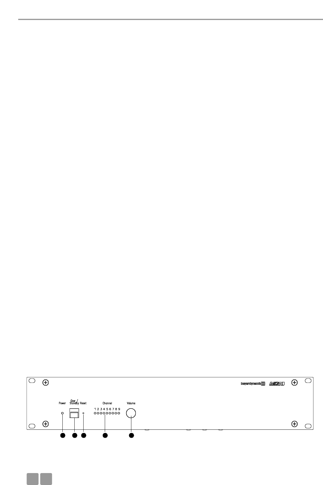
MCW-D 50 Control Unit
E
30
Thank you for selecting the MCW-D 50 Digital wireless conference system. Please take some time to read carefully through this
manual before setting up the equipment.
This manual describes the installation and operation of the system without control and configuration via PC.
The following components are needed for the operation of a system without PC:
• MCW-D 50 control unit
• MCW-D 521 delegate microphone unit
• MCW-D 523 chairman microphone unit
The MCW-D 50 control unit is available in two versions:
MCW-D 50-3 for discussions with a maximum of 3 participants (e.g. 2 delegates and 1 chairman) speaking simultaneously.
MCW-D 50-9 for discussions with a maximum of 9 participants (e.g. 7 delegates and 2 chairmen) speaking simultaneously.
For more information about the control and configuration of the MCW-D 50 system via PC please refer to the MCW-D 50
Conference Software manual.
3. MCW-D 50 Control Unit
The MCW-D 50 control unit is the heart of the system. It controls the delegate and chairman microphone units. With the
standard version of the MCW-D 50 control unit a maximum of 3 speakers (e.g. 2 delegates and 1 chairman) can speak
simultaneously.
3.1 Controls and Indicators
Front
1 2 3 4 5
Control Unit
FCC ID: OSDMCWD50
Canada: IC: 3628A-MCWD50
Microphone Units
FCC ID: OSDMCWD5xx
Canada: IC: 3628A-MCWD5xx
This equipment has been tested and found to comply with the limits for a Class B digital device, pursuant to Part 15 of the FCC
Rules. These limits are designed to provide reasonable protection against harmful interference in a residential installation. This
equipment generates, uses and can radiate radio frequency energy and, if not installed and used in accordance with the
instructions, may cause harmful interference to radio communications. However, there is no guarantee that interference will
not occur in a particular installation. If this equipment does cause harmful interference to radio or television reception, which
can be determined by turning the equipment off and on, the user is encouraged to try to correct the interference by one or
more of the following measures:
• Reorient or relocate the receiving antenna.
• Increase the separation between the equipment and receiver.
• Connect the equipment into an outlet on a circuit different from that to which the receiver is connected.
• Consult the dealer or an experienced radio/TV technician for help.
In accordance with FCC requirements, changes or modifications not expressly approved by beyerdynamic GmbH & Co. KG could
void the user’s authority to operate this product. Any changes or modifications not expressly approved by the party responsible
for compliance could void the user’s authority to operate this equipment.
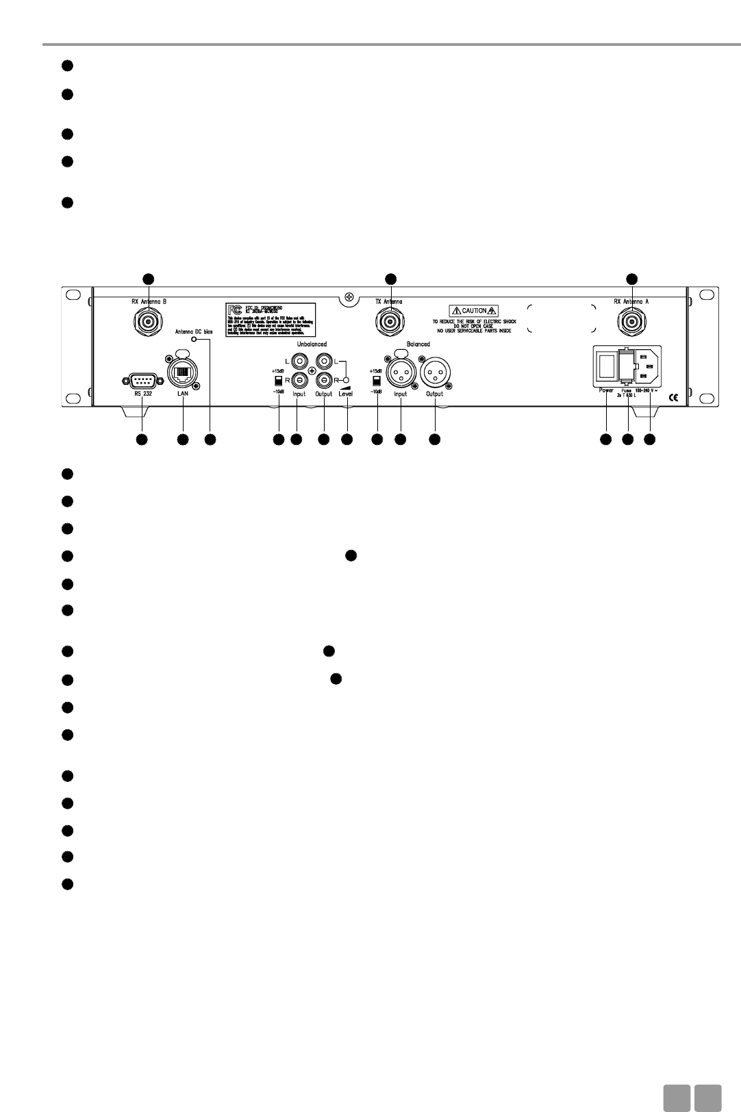
MCW-D 50 Control Unit
E31
RS 232 port for the connection of PC or media control system (9-pin Sub-D)
LAN network connection for PC
Control LED for antenna powering 5 V DC (green = normal DC ; flashing red rapidly = short circuit)
Switch -10 dB / +15 dB for unbalanced input (RCA)
Input, RCA, unbalanced, for the connection of external devices such as CD players (L + R)
Output - master output, RCA, unbalanced, for the connection of external devices such as mixing consoles,
sound contracting systems or recorders (L + R)
Level control for Output - master output, RCA
Switch -10 dB / +15 dB for balanced input (XLR)
Input, 3-pin XLR female, balanced, for the connection of external sound sources (+6 dBm)
Output - master output, 3-pin XLR male, balanced, for the connection of external devices such as mixing consoles,
or sound contracting systems
ON/OFF-switch
Fuse
Mains supply
Connection for receiving antennae
Connection for transmitting antenna
6
7
8
9
10
10
10
11
11
12
13
14
14
15
16
17
18
19
20
Power LED. LED is illuminated green when the unit is switched on.
Standby button. When this button is pressed for more than 3 seconds all switched-on microphone units are switched off.
When this button is pressed shortly all allocated microphones are switched off.
Reset. This button resets the system into the switch-on state (to press the reset button use a paper clip).
LEDs to indicate the status of the receiving channels. LED is illuminated green: the channel is vacant.
LED is illuminated red: the channel is occupied.
Volume control for the loudspeakers of the microphone units
1
2
3
4
5
Rear
3.2 Setting up
3.2.1 Where to place the Control Unit
• If you do not use remote antennae*, place the MCW-D 50 control unit in the room where the meeting takes place. If you use
remote antennae*, place them in the conference room.
• Do not place the MCW-D 50 control unit near digitally controlled equipment.
*Important note for the USA and Japan: At present only the use of the CA 2413 remote antennae is permitted.
6 7 11 12 13 14 15 16 17 18
192019
98
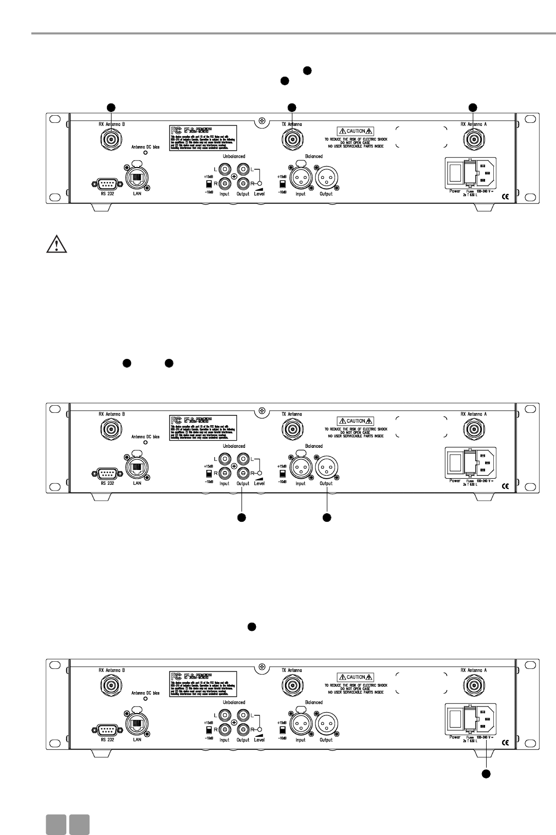
MCW-D 50 Control Unit
E
32
3.2.2 How to connect the Antennae
• Connect the receiving antennae to the antenna inputs A and B .
• Connect the transmitting antenna to the antenna output .
• For stand-alone-operation we recommend using the CA 2411 angled rod antenna.
3.2.3 Audio Connection
• Connect the XLR or RCA master output to the input of a mixing console/amplifier.
• Always route cables running to the unit where they will not be pinched or cut by heavy or sharp objects.
3.2.4 Power Supply
• Verify that the voltage rating of the unit matches that of the AC mains outlet you are to use. If you connect the unit to the
wrong voltage, you may seriously damage it.
• Always route cables running to the unit where they will not be pinched or cut by heavy or sharp objects.
• Connect the MCW-D 50 control unit to the mains . The internal power supply unit of the control unit can adjust auto-
matically between 100 V and 240 V at 50 - 60 Hz.
Important:
• There must be an unobstructed path between the microphone units and the antennae, i.e. between the
MCW-D 50 control unit and the microphone units there must not be any obstacles. The range is around
30 - 50 m. For optimum range the surface of the table is important, wood or plastic tables are ideal, but metal tables
can cause interferences and reduce the range.
15 11
1920
20
19
19
11 15
1818
18
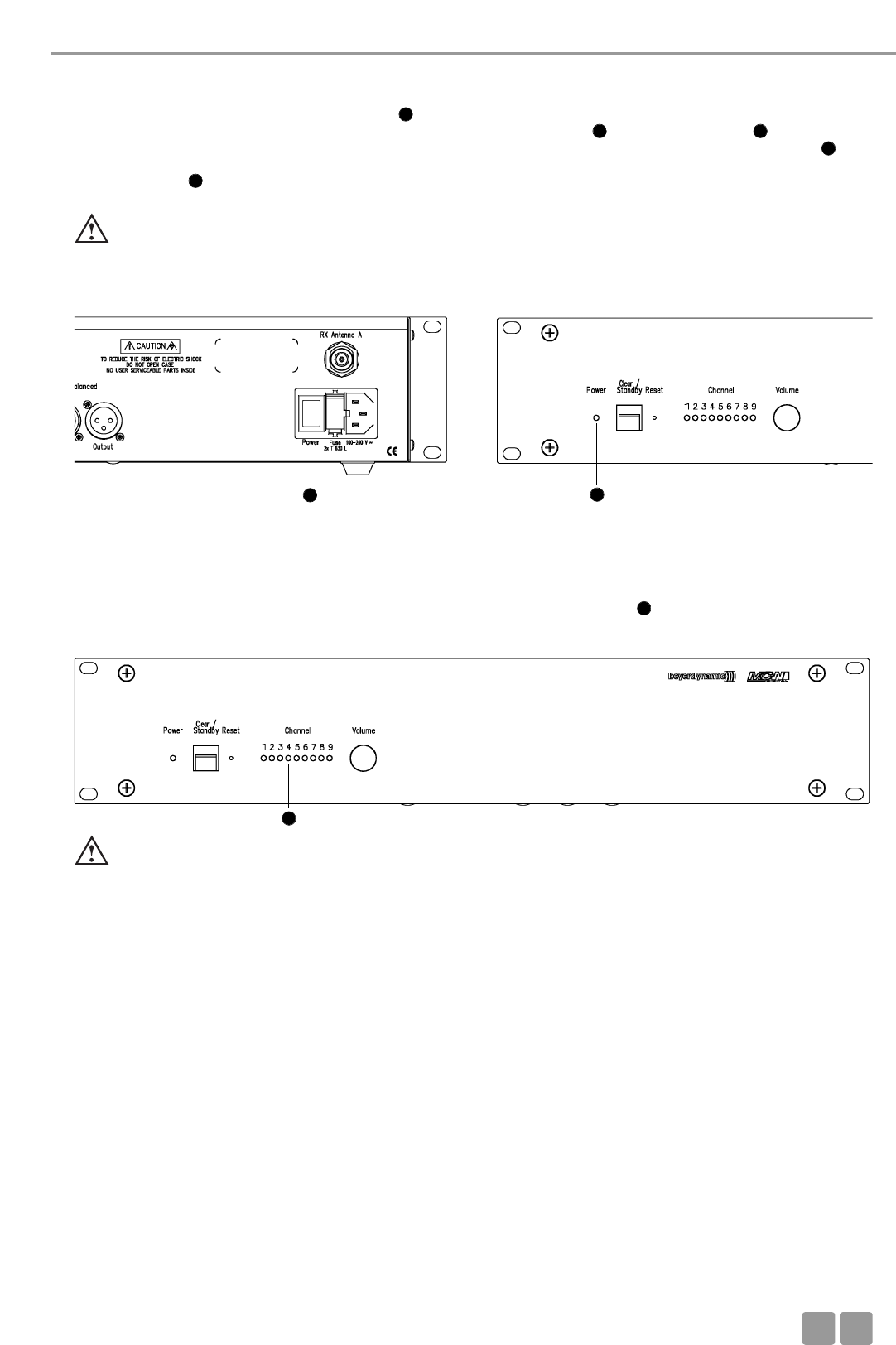
MCW-D 50 Control Unit
E33
3.2.5 How to switch the Control Unit on/off
• Switch on the MCW-D 50 with the On/Off-switch on the rear.
• During the first 30 seconds the MCW-D 50 control unit is started, the Power LED and the Channel LEDs are flashing red
and an operation is not yet possible. If the MCW-D 50 control unit is connected to a network via the LAN connection , the
MCW-D 50 control unit will be ready for operation after approx. 20 seconds.
• The Power LED on the front will illuminate green, when the control unit is ready for operation.
•CAUTION: Always turn off the power when making input or output connections.
Rear Front
3.2.6 Channel Indication
• Depending on the configuration of the MCW-D 50 control unit 3 or more channel-LEDs will illuminate green
(standard: 3 channels).
3.2.7 Rack Mounting
• When mounting the MCW-D 50 control unit into a 19"-rack housing leave 1 HU for a ventilation panel above and
under the control unit.
3.2.8 Volume Control
• The volume of the microphone units is controlled with the virtual volume control of the MCW-D 50 Conference Software.
Important:
• If the MCW-D 50 control unit is equipped with more than one module, but there are not more than 3 LEDs illuminated,
please check if individual modules have been deactivated with the MCW-D 50 Conference Software.
16
1
1 4
7
4
16 1
4
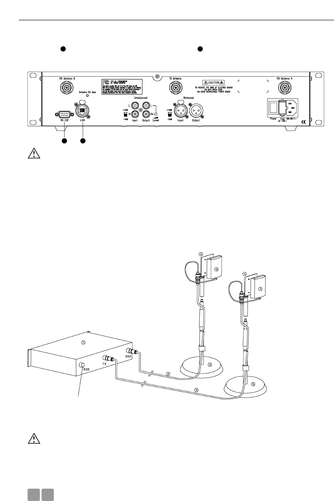
MCW-D 50 Control Unit
E
34
3.2.9 Connection of Media Control System and PC
• If you want to connect a media control system and a PC to the MCW-D 50 control unit, connect the PC to the LAN network
connection and the media control system to the RS 232 connection .
• For the direct connection of the LAN network connection to a PC you must use a crossover cable.
• The LAN settings are explained in the protocol of the MCW-D 50 Conference Software.
3.3 Connecting and Positioning of remote Antennae*
The MCW-D 50 control unit can also be operated with remote antennae. Low attenuation connecting cables are available in
different lengths. Please note that all three antennae have to be connected remotely. The transmitting antenna should be
mounted in the centre and the receiving antennae on the left and right. The range can be increased by using a directional
antenna (e.g. CA 2413, gain approx. 6 dB).
Depending on the cable attenuation you should use antenna amplifiers if the cables are long.
Installation with remote antennae*
Important:
• Never access the MCW-D 50 control unit via the media control system and the MCW-D 50 Conference Software
simultaneously. In this case a correct function of the system cannot be guaranteed.
6
6
7
7
(1) MCW-D 50 control unit
(2) CA 2421/2422 or
CA 2431/2432 antenna cable
(3) CA 2413 planar antenna
(4) CA 2462 mounting kit 3/8"
(5) ST 600 stand 3/8"
refer to RX A
The CA 2413 planar antenna is connected to the MCW-D 50 control unit and mounted onto a stand with the CA 2462 mounting
kit. For more information refer to the “MCW-D Design Guide”.
Important:
• There must be an unobstructed path between the microphone units and the antennae, i.e. between the
MCW-D 50 control unit and the microphone units there must not be any obstacles. The range is around
30 - 50 m. For optimum range the surface of the table is important, wood or plastic tables are ideal, but metal tables
can cause interferences and reduce the range.
*Important note for the USA and Japan: At present only the use of the CA 2413 remote antennae is permitted.
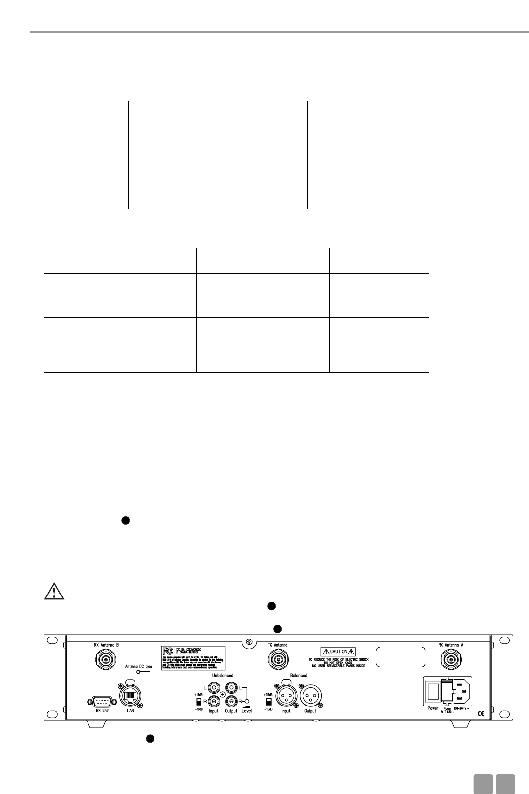
MCW-D 50 Control Unit
E35
3.4 Remote Supply of the Antenna Amplifier via the Control Unit**
The antenna amplifiers can be supplied remotely via the MCW-D 50 control unit. On the rear of the MCW-D 50 control unit
there is a status LED .
This LED will illuminate green, when the remote supply voltage is 5 V at all antenna sockets.
The LED is flashing red rapidly, when there is a short-circuit at the antenna socket. In this case check the antenna cables.
The remote supply voltage of 5 V supplies the CA 2441 RT and CA 2441 T antenna amplifiers.
• Size of the room: up to 400 m2 (20 x 20)
• Number of participants: 30 - 100
• Antenna position: The antennae should be placed as high as possible above the table
in a position close to the participants.
• Alignment: Place the antennae so that they point to the participants (the convex side must point to the front).
We recommend to use the CA 2441 antenna amplifier if the cable attenuation exceeds 12 or 15 dB, i.e. if the CA 2420 cable is
longer than 40 m or the CA 2430 cable is longer than 60 m.
Cable attenuation of different cables in 2.4 GHz applications
Cable type
Cable length 100 m 50 m 30 m
RG 58 100 dB 50 dB 30 dB not suitable
RG 213 U 49 dB 24 dB 15 dB short cable
Aircell 7, CA 2420 41 dB 20 dB 12 dB normal cable
Ecoflex 10, CA 2430 24 dB 12 dB 7 dB long cable
Aircell 7
Standard
CA 2420
Ecoflex 10
Low Attenuation
CA 2430
Max. cable length max. 20 m
= 1 x CA 2422
or 2 x CA 2421
max. 40 m
Min. bending radius 25 mm 40 mm
ATTENTION:
• The CA 2441 RT and CA 2441 T antenna amplifiers may be only powered with 5 V DC.
• When you connect a CA 2441 RT to the TX output of the MCW-D 50 you should use a connecting cable with an
attenuation of at least 10 dB.
8
8
Important Note:
To comply with FCC RF exposure compliance requirements, the following antenna installation and device-operating configuration
must be satisfied. Only authorized and certified beyerdynamic systems integrators may perform the installation of antennae.
There are no user serviceable parts or processes. Connect the receiving antennae to the antenna inputs A and B. Connect the
transmitting antenna to the appropriate output. To maintain compliance with the FCC’s RF exposure guidelines, this transmitter
and its antenna must maintain a separation distance of least 20 centimetres from all persons.
20
20
**The use of the CA 2441 RT/T antenna amplifier is prohibited in the USA.
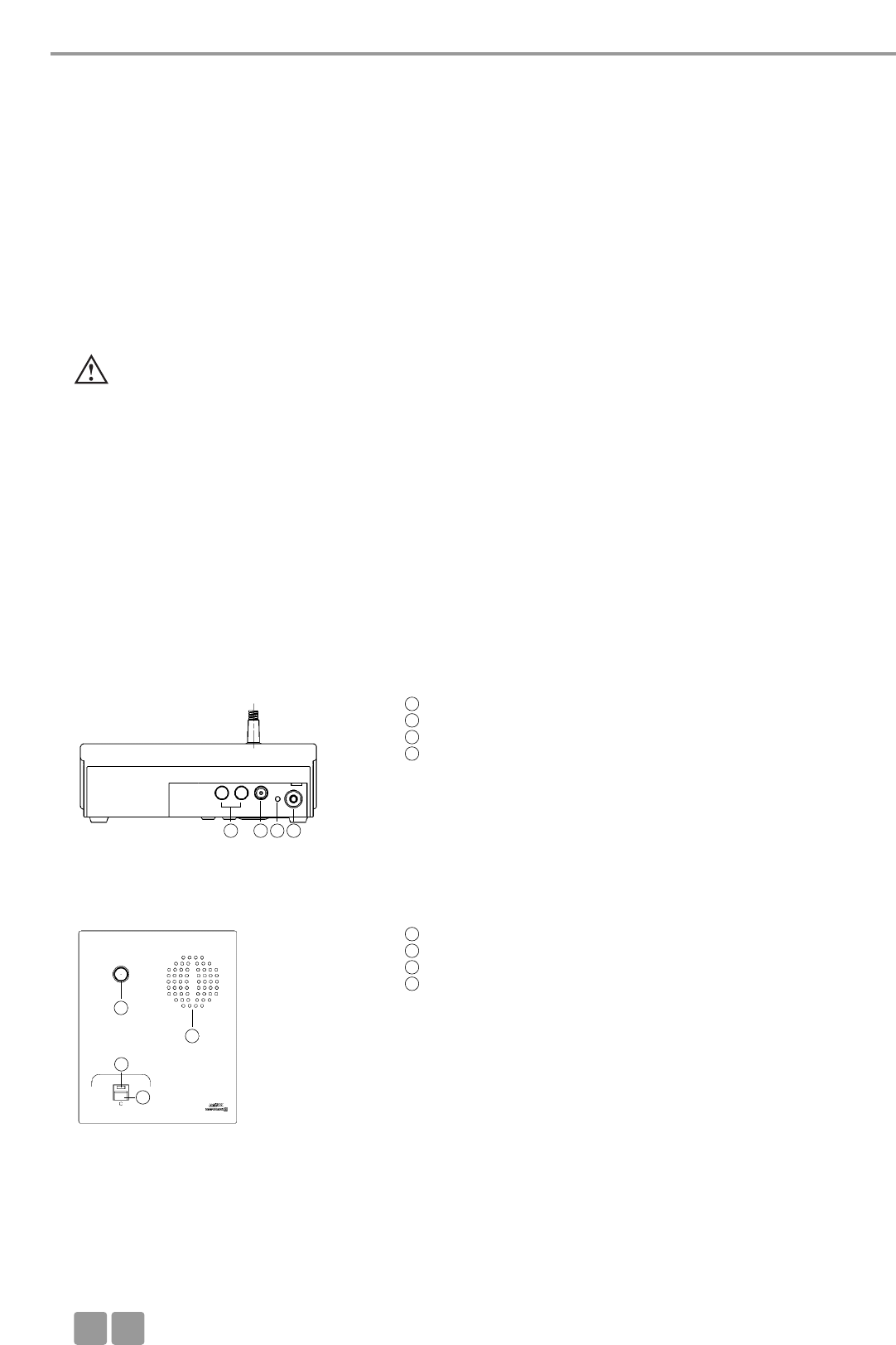
Microphone Units
E
36
4. Delegate and Chairman Microphone Units
• At the factory each microphone unit is programmed with a different serial number so that the MCW-D 50 control unit can
control them. The serial number is printed on the bottom of each microphone unit.
• Via radio communication each microphone unit is addressed in the transmission protocol via an individual ID number. This ID
number can be changed with the MCW-D 50 Conference Software. On delivery the ID number corresponds to the last four
digits of the serial number.
• When you order more microphone units later, please inform the supplier of the configuration of the control unit and the
identity / serial numbers of the microphone units.
4.1 MCW-D 521 / 523 Microphone Units
4.1.1 Controls and Indicators
Important:
• The charging contacts of the microphone units can cause damages, injuries or fire damages if they come into
contact with conductive materials such as jewelry, keys or chains. This can lead to a closed circuit and heat up the material.
•To avoid overstretching and premature wear and tear, always adjust the gooseneck microphone via the
lower flexible part of the microphone and never the microphone head or rigid tube. The gooseneck can
only be bent 90° at maximum.
• If the microphone units are to be operated by an external power supply, you can use the CA 2457 power supply/
charger only.
Charging contacts for CC 10, CD 10 charger
DC socket for charging the microphone unit and for DC operation
Operating control LED (green / red)
Stereo jack socket (3.5 mm) to connect recorders or headphones
(e.g. DT 1)
Rear view
Gooseneck microphone with illuminated ring
Loudspeaker
LED to indicate the function (green/red)
Microphone button
Top view MCW-D 521 delegate microphone unit
1
1
2
3
4
5
6
7
8
234
5
6
7
8
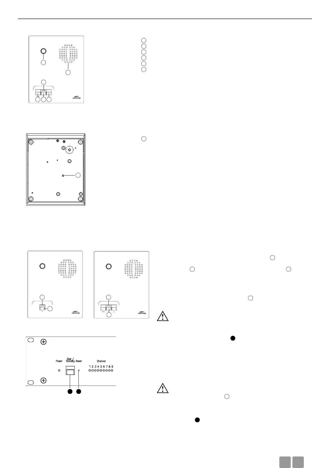
Microphone Units
E37
Gooseneck microphone with illuminated ring
Loudspeaker
LED to indicate the function (green/red)
Microphone button
Clear button to clear the delegate microphone units
Function button for optional functions (refer also to chapter 6.2)
Top view MCW-D 523 chairman microphone unit
4.1.2 Switching on / off
Delegate Chairman Switching on
• The microphone units have no separate on/off switch. They are
switched on and off with the microphone button .
• By pressing the button briefly, the microphone unit is switched
on. The LED flashes for a moment and the green LED on
the rear is illuminated.
Switching off
• By pressing the button for more than 2 seconds the micro-
phone unit is switched off and the LED will flash twice
orange briefly.
• If you press the standby button of the MCW-D 50 control unit
for more than 3 seconds, you switch off all switched-on MCW-D
microphone units within the range of the MCW-D 50 control unit.
• Furthermore, the microphone units are switched off automatically,
when they do not receive a signal from the MCW-D 50 control
unit for more than 3 minutes.
Important:
• If the microphone unit is out of range of the MCW-D 50
control unit, the LED will flash red. After approx. 3
minutes the microphone unit will switch off automatically.
• If the system should fail to operate, i.e. the microphone
unit is switched on but no sound is heard, press the reset
button of the control unit. Should the system still fail
to operate, check the audio configuration with the
MCW-D 50 Conference Software. If the system still fails to
operate then, please contact your beyerdynamic
representative.
Important:
• With the MCW-D 50 Conference Software you can
disable manual deactivation of the microphone unit.
5
6
6
7
8
9
5
7
89 10
8
8
7
7
7
3
10
Bottom view MCW-D 521 / MCW-D 523
Counter-sunk Reset button
11
8
2
2
3
3
7 7
11
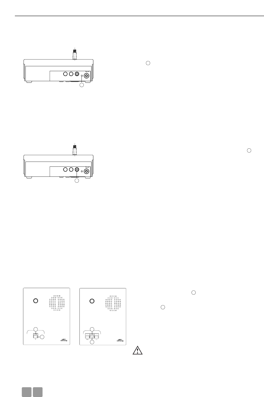
Setting up
E
38
4.2 Powering / Operating Time
• The microphone units have an integrated rechargeable battery allowing
an operating time of 20 hours.
• As soon as the capacity is too low for a satisfactory operation, the operating
control LED will flash. The remaining time of operation is around 60
minutes.
• The supplied MCW-D 50 Conference Software indicates the decreasing
battery voltage on a PC or external media control system connected to the
MCW-D 50 control unit.
Rear view microphone unit
4.3 Powering with external CA 2457 Power Supply Unit
• The MCW-D microphone units can be also powered with the CA 2457
external power supply unit which can be connected to the DC socket
on the rear of the microphone unit.
• During the time the power supply unit is connected, the microphone
unit is also being charged. Please refer also to chapter 8. Battery
Charging with external Power Supply Unit.
Rear view microphone unit
4.4.1 Normal Operating Mode
4.4 Operating Modes
• The different operating modes such as Normal, Push-To-Talk or Voice Activation are adjusted with the MCW-D 50 Conference
Software. The standard operating mode is Normal. Please refer also to the appropriate MCW-D 50 Conference Software
manual.
• Press the microphone button to switch on the gooseneck
microphone.
• Red ring of the gooseneck microphone is illuminated
and the LED is illuminated green: The microphone is ready
for talking.
• Using the MCW-D 50-3 control unit 3 participants (e.g. 2 delegates
and 1 chairman) can speak simultaneously. Using the
MCW-D 50-9 up to 9 participants (e.g. 8 delegates and 1 chairman)
can speak simultaneously.
Important:
• If the number of open microphones is reached, a
microphone can only be switched on manually
when another microphone unit has been switched
off.
Delegate Chairman
3
3
2
2
8
7
7
8
8
7
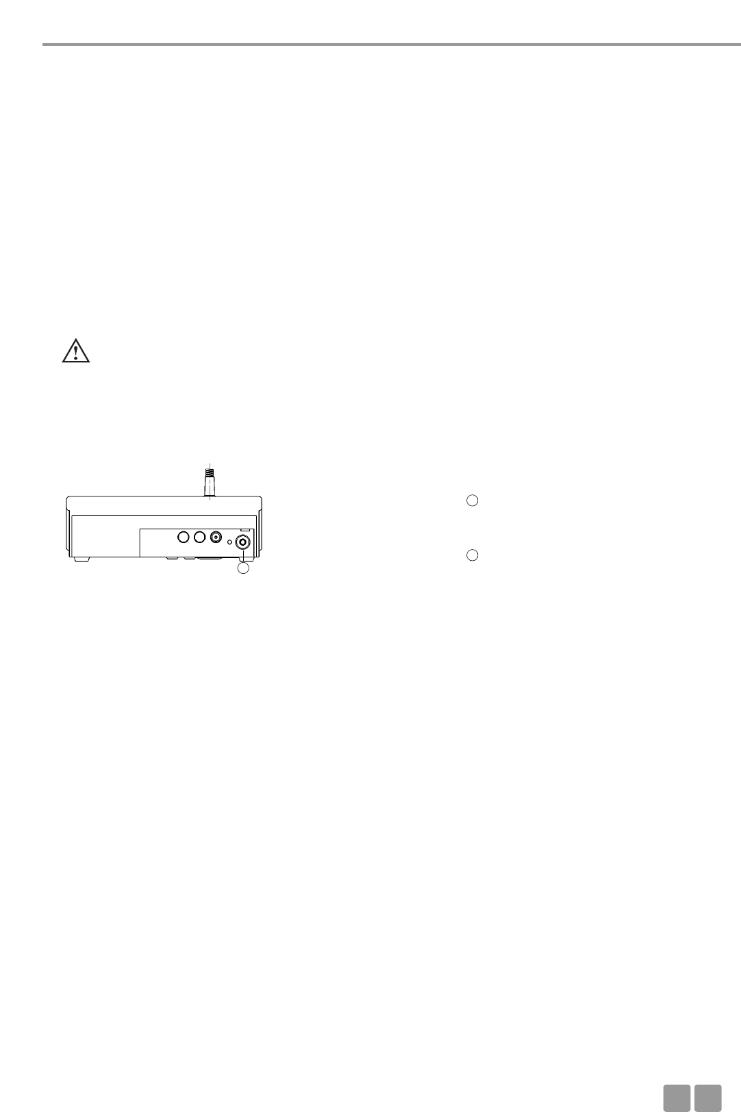
Setting up
E39
4.5 How to record the Meeting
• For recording the meeting you can connect a recorder (e.g. a laptop
with the steno-s Conference and Recording software) to the
documentation output .
• The volume can be adjusted with a PC using the MCW-D 50 Conference
software.
• Instead of a recorder it is also possible to connect a headphone to the
documentation output . We recommend an impedance of 600 Ω.
Although a lower impedance does not damage the microphone unit, but
the headphone operation can be disturbed.
4.6 Maintenance of the MCW-D Microphone Units
• For cleaning the MCW-D microphone units when they are slightly dirty (finger prints, dust, jam or juice) use a soft, damp
cloth, sponge or brush and a liquid cleaning agent.
• Before cleaning the surface it must be moistened thoroughly. Afterwards it must be cleaned with a damp cloth.
• Make sure not to allow any water to enter the unit.
• For dirt caused by mineral oils and fats, animal and vegetable fats use spirit, isopropyl alcohol or benzine.
• For dirt caused by ballpoint pens, typewriter ribbons or carbon paper use isopropyl alcohol or spirit.
• Clean the charging contacts of the microphone units with spirit or isopropyl alcohol from time to time.
• Clean the supplied pop shield with clear water. Make sure that it is completely dry before you put it on the microphone
again.
4.4.2 FiFo-Mode
• If the microphone units operate in the FiFo-mode (first in - first out), the microphone unit that was switched on first, will be
switched off, when another microphone unit is switched on and the number of open microphones (NOM) will be exceeded.
4.4.3 Push-To-Talk Mode
• If the microphone units operate in the Push-To-Talk mode (PTT) the microphone button must be pressed as long as someone
speaks into the microphone.
4.4.4 Voice Activation Mode
• If the microphone units operate in the Voice Activation mode, the microphone units are switched on via voice control. That
is the microphone unit is switched on as soon as someone speaks into the microphone. In this case it is not necessary to press
the microphone button.
Important:
• The threshold and the hold time can be configured with the MCW-D 50 Conference software for all microphone
units.
4
4
4
5. Programmable Functions of the Microphone Units with the
MCW-D 50 Conference Software
The functions of the microphone units described in the following are only available, when they have been programmed
with the MCW-D 50 Conference software before. Please refer to the corresponding MCW-D 50 Conference Software manual.
5.1 Safety Code
Using the MCW-D 50 Conference software an alphanumerical code can be entered for the MCW-D microphone units and the
MCW-D 50 control unit within one system. This will increase the safety against unauthorised listening. Microphone units which
do not have this code are not recognised by the control unit and will be deactivated.
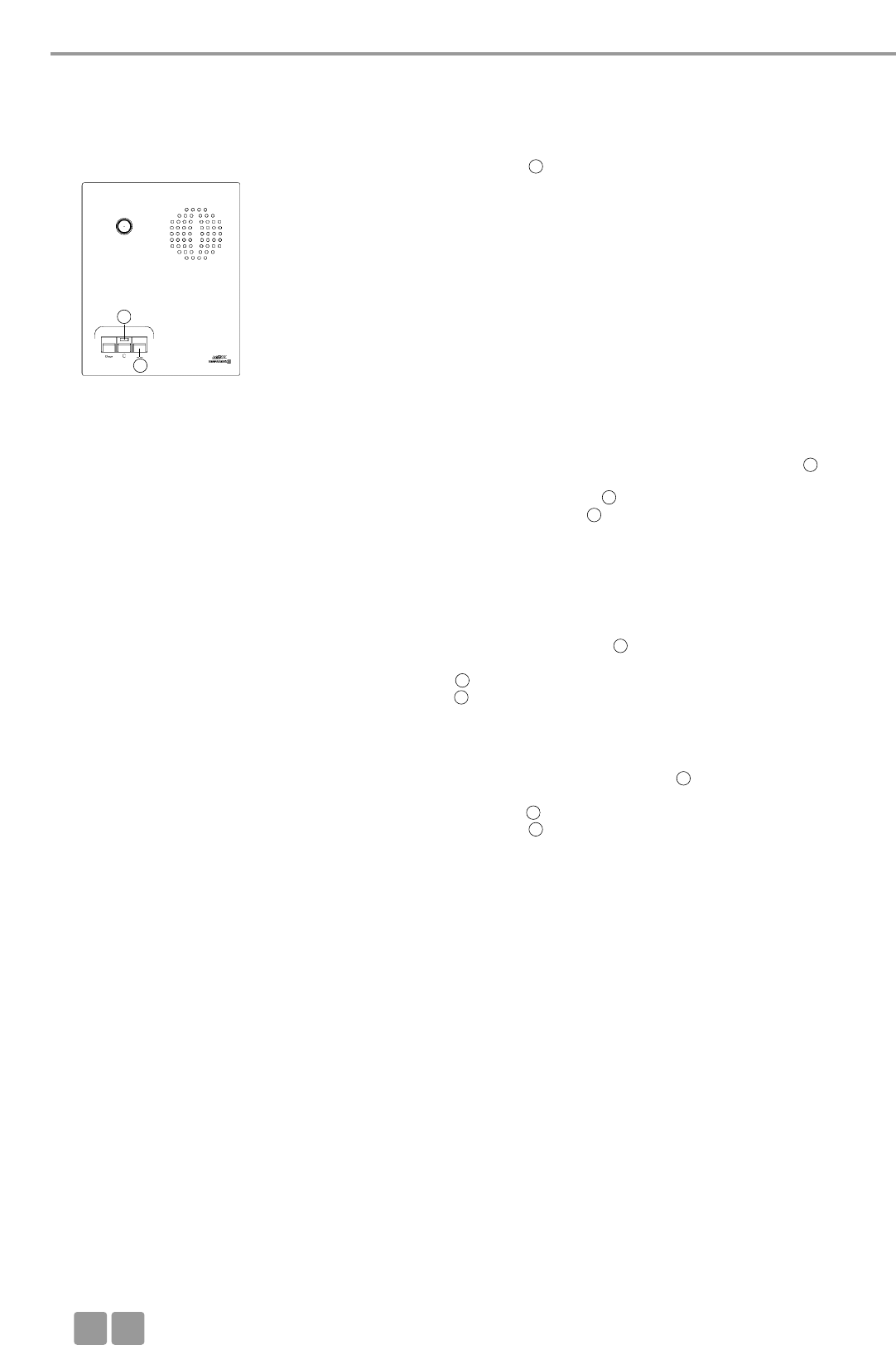
Setting up
E
40
5.2 Function button of the MCW-D 523 Chairman Microphone Unit
Depending on the configuration the following functions are possible with
the function button : mute, clear or priority. The function button can be
configured via the control unit with the MCW-D 50 Conference software.
1. Normal
All delegate microphone units will be cleared and the microphone of
the chairman unit will be switched on. The delegates can switch on
their microphones again, when the chairman switches off his micro-
phone.
2. Mute
All delegate microphone units which were activated before, will be
muted when the chairman is speaking and will be re-activated when
the chairman switches off his microphone.
3. Clear
All delegate microphone units are cleared and can be switched on
afterwards.
4. How to mute Aux-In ports
First push mutes the port, the next one enables it, third one mutes
again etc.
If the chairman presses the priority button, the audio signal at the Aux
Input of the MCW-D 50 control unit will be muted. The LED of the
chairman unit will start flashing red (slowly). When the chairman turns
on his microphone, the LED will flash green (slowly). If the chairman
turns off priority the LED will illuminate green permanently, if the
microphone is still on.
5. How to mute Aux-In ports & clear all active delegates, pushing prior
button a second time will release AUX-In muting. Pushing prior button
a third time will mute Aux-In ports and clear all active delegate units
again, etc.
If the chairman presses the priority button, the audio signal at the Aux
Input of the MCW-D 50 control unit will be muted and all delegate
units will be cleared. The LED of the chairman unit will start
flashing red (slowly). When the chairman turns on his microphone, the
LED will flash green (slowly). If the chairman turns off priority the
LED will illuminate green permanently, if the microphone is still on.
6. How to mute Aux-Out ports
First push mutes the port, the next one enables it, third one mutes
again etc.
If the chairman presses priority, the audio signal at the Aux Output of
the control unit will be muted. The LED of the chairman unit will
start flashing red (slowly). When the chairman turns on his micro-
phone, the LED will flash green (slowly). If the chairman turns off
priority the LED will illuminate green permanently, if the micro-
phone is still on.
7. “COM Message” Function
A command is sent via the RS 232 serial interface from the MCW-D 50
control unit and a programmed function is carried out via a media
control system for instance (e.g. light control).
For the other functions there is also a command sent via the RS 232
serial interface from the MCW-D 50 control unit.
8. Custom
Two different commands according to the duration of the push
< 1 second = command “Short press string” is transmitted
> 1 second = command “Long press string” is transmitted
These commands can be set individually with the MCW-D 50
Conference Software.
Chairman microphone unit
10
10
7
7
7
7
7
7
7
7
7
7

Setting up
E41
6. CD 10 Charger in CC 10 Case
• With the integrated CD 10 charger in the CC 10 transport case, it is possible to charge a maximum of 10 microphone units.
The battery state can be seen from the outside through a window.
• The CC 10 transport case can be extended with more CD 10 chargers for 10 microphone units each.
The CD 10 charger has a compartment for storing accessories such as headphones.
6.1 First Use
• To achieve a 100% battery capacity all microphone units should have 2 complete charging cycles (charging and discharging)
at least. Only after several charging and discharging cycles the rechargeable batteries will achieve their full capacity.
5.3 Request-to-Talk Mode
• This operating mode is only possible in conjunction with a PC using the
MCW-D 50 Conference software or media control system (AMX®,
Crestron®, Cue etc.).
• The request-to-talk is registered in the system by pressing the micro-
phone button of the microphone unit.
• The allocation is made by the operator at the PC or touch screen of the
media control system.
• The LED is illuminated red to indicate the request-to-talk.
• If you press the microphone button again the request-to-talk is
cleared. The LED goes out.
Delegate microphone unit
6.2 Charging Process
1. Connect the charger to AC power and switch it on. The switch will illuminate.
2. Put the switched-off microphone units into the charging compartments. If microphone units are switched on, they are
switched off automatically. When the microphone units are used again, they must be switched on.
3. The charging process is indicated by the gooseneck LED ring and can be seen from the outside through a window.
a) Gooseneck LED ring is flashing red . . . . . . . . . . . . . . . Battery is charged
b) Gooseneck LED ring illuminates red permanently. . . . Battery is full
c) Gooseneck LED ring is flashing red rapidly . . . . . . . . . Error
Note:
• If an error has occurred, try to start the charging process once again. If the LEDs are still flashing rapidly, please contact
your beyerdynamic dealer.
• The charging time is around 2 hours when the battery is completely empty.
• After some time the capacity of the rechargeable batteries is reduced technically. This will reduce the operating time.
• It is normal that the rechargeable batteries are heated up during the charging process.
• Clean the charging contacts with spirit or isopropyl alcohol from time to time.
7
8
8
7
7
8
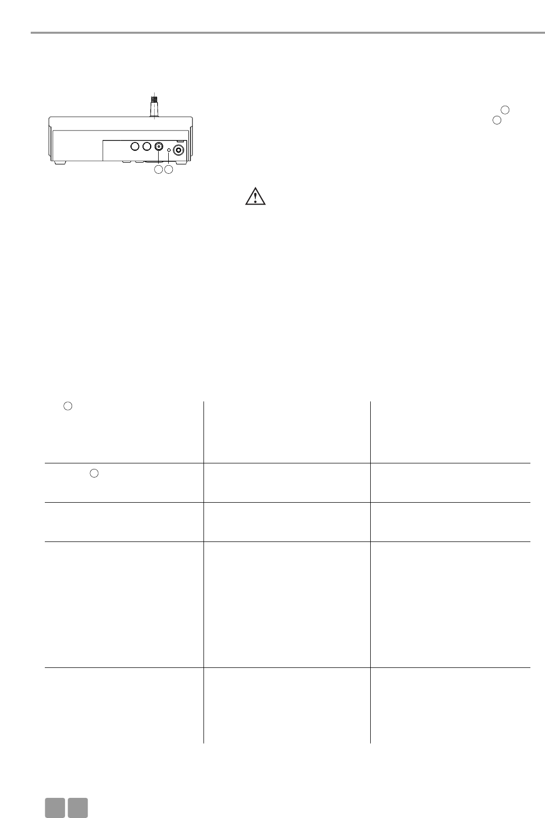
Trouble Shooting
E
42
7. Battery Charging with external Power Supply Unit
• The MCW-D microphone units can be also charged with the external
CA 2457 power supply unit, which is connected to the DC socket .
• The charging process is indicated by the operating control LED .
LED indication during charging the battery:
a) Operating control LED is flashing red . . . . . . . . . . . . . . Battery is
charged
b) Operating control LED illuminates red permanently . . . Battery is full
c) Operating control LED is flashing red rapidly. . . . . . . . . Error
Rear view
Important:
• After some time the capacity of the rechargeable batteries is
reduced technically. This will reduce the operating time.
•It is normal that the rechargeable batteries are heated up
during the charging process.
• The charging time is around 5 hours when the battery is
completely empty.
• If the microphone unit is switched on during the charging
process, the LED will illuminate green.
8. Trouble Shooting
If problems occur that you do not find listed below, the MCW-D system should be adjusted to the standard configuration with
the MCW-D 50 Conference software. Please refer to the appropriate manual.
Problem
LED flashes red rapidly
Power LED flashes
Microphone unit goes off
Allocation is not possible
Microphone unit cannot be switched
on
Possible Cause
• Control unit is not switched on
• Microphone unit is not within the
range of the control unit
• Frequency bands have been
configured incorrectly
• Battery is almost empty
• Low battery warning to indicate that
the battery is almost empty
• Check if the battery is still full
• PIN Code is activated
• Control unit is not switched on
• All channels are occupied
• Check the number of open micro-
phones (NOM) with the MCW-D 50
Conference software
• Microphone unit is not within the
range of the control unit
• Check the adjusted frequency bands
• Interference caused by WLAN
• Control unit is not switched on
• Check the number of open micro-
phones (NOM) with the MCW-D 50
Conference software
• Check the battery
• Microphone unit is not within the
range of the control unit
Solution
• Switch on the control unit
• Reduce the distance between
control unit and microphone units
• Check the adjusted frequency bands
with the MCW-D 50 Conference
Software
• Recharge the battery inside the
microphone unit
• If the battery is empty recharge it
• Deactivate PIN Code
• Switch on the control unit
• Switch off an activated microphone
• If possible increase the number of
open microphones (NOM) with the
MCW-D 50 Conference software
• Reduce the distance between
control unit and microphone units
• Use the standard adjustments
mentioned in the MCW-D 50
Conference manual
• Select another frequency band for
the RF module(s) with the MCW-D 50
Conference Software
• Switch on the control unit
• If possible increase the number of
open microphones (NOM) with the
MCW-D 50 Conference software
• If the battery is empty recharge it
• Reduce the distance between
control unit and microphone units
2
2
3
3
7
3
Trouble Shooting
E43
Possible Cause
• Check the volume adjustment with
the MCW-D 50 Conference Software
• “Disable Manual Power Off”
function is activated
• Operating mode Push-To-Talk or
Voice activated is active
• Crash of the microcontroller inside
the microphone unit
• Microphone unit is not switched on
• Headphone is not connected
properly
• Check the volume adjustment with
the MCW-D 50 Conference Software
• Check the external loudspeakers
• Check the audio level
• Microphone unit is not within the
range of the control unit
• Check the antenna positioning and
the antenna cable
• Check the line of sight between
microphone unit and antenna
• Interferences caused by devices such
as Wireless LAN
Solution
• Increase the volume with the
MCW-D 50 Conference Software or
the Volume control of the
MCW-D 50 control unit
• Deactivate “Disable Manual Power
Off” function with the MCW-D 50
Conference Software
• Deactivate the operating mode
Push-To-Talk or Voice activated with
the MCW-D 50 Conference Software
• Switch off the microphone units via
the control unit by pressing the
Clear/Standby button more than 3
seconds.
• Switch off the control unit. The
microphone units will go off after
approx. 3 minutes.
• Press the counter-sunk Reset
button on the bottom of the micro-
phone unit.
• Switch on the microphone unit
• Connect the headphone properly
• Increase the volume with the
MCW-D 50 Conference Software or
with the volume control of the
MCW-D 50 control unit
• Correct the volume and position of
the loudspeaker
• Reduce the input level of the
control unit
• Reduce the distance between
control unit and microphone units
• If necessary use an antenna
amplifier
• Remove obstacles between micro-
phone units and antennae; do not
place any objects in front of the
antennae of the control unit
• Select another frequency band for
the RF module(s) with the MCW-D 50
Conference Software. Refer also to
chapter 8.1.
Problem
Loudspeaker of the microphone unit
does not work
Microphone unit cannot be switched
off
Documentation output does not work
Feedback
Interferences; noise
Short drop-outs
8.1 Simultaneous Operation of the MCW-D Discussion System and other 2.4 GHz Devices
(e.g. WLAN, Bluetooth)
8.1.1 Physical laws
Due to many physical laws it is not possible to guarantee a simultaneous interference-free operation of different devices using
the same frequency band. Radio devices operating in the same frequency band will always disturb each other (the function can
be disturbed as well).
For the use of UHF wireless microphones it is known that never 2 devices can be operated on the same frequency. The way
technology is at the moment, it is only possible to operate a certain number of compatible radio devices within a defined fre-
quency band.
This applies also to the 2.4 GHz-ISM band (2400 MHz - 2484 MHz). Due to digital transmission techniques and various transmis-
sion standards it is possible, but not recommended, to operate certain devices simultaneously within the same frequency band.
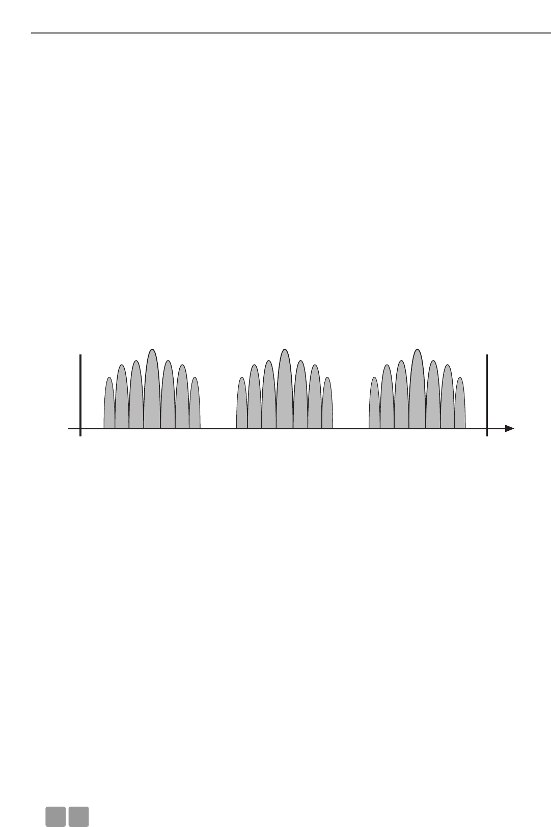
8.1.2 MCW-D and WLAN or WiFi
As WLAN, the MCW-D 50 system uses the same bandwidth of approx. 22 MHz for each RF channel (Low, Mid, High). This results
in three compatible RF channels in the 2.4 GHz-ISM band. These are theoretically:
Compatible channel 1: 2400 MHz - 2428 MHz (theoretical mid frequency: 2414 MHz)
Compatible channel 2: 2428 MHz - 2456 MHz (theoretical mid frequency: 2442 MHz)
Compatible channel 3: 2456 MHz - 2484 MHz (theoretical mid frequency: 2470 MHz)
The MCW-D 50 system uses RF channels (Low, Mid, High) compatible to each other. For WLAN the user has to configure compa-
tible RF channels.
Frequencies MCW-D 50 / WLAN
MCW-D 50 WLAN
Channel. . . . . . . . . . . . . . . . . Centre frequency Channel . . . . . . . . . . . . . . . . Centre frequency
Low . . . . . . . . . . . . . . . . . . . . 2412 MHz 1 . . . . . . . . . . . . . . . . . . . . . . . 2412
2 . . . . . . . . . . . . . . . . . . . . . . . 2417
3 . . . . . . . . . . . . . . . . . . . . . . . 2422
4 . . . . . . . . . . . . . . . . . . . . . . . 2427
5 . . . . . . . . . . . . . . . . . . . . . . . 2432
Mid. . . . . . . . . . . . . . . . . . . . . 2438 MHz 6 . . . . . . . . . . . . . . . . . . . . . . . 2437
7 . . . . . . . . . . . . . . . . . . . . . . . 2442
8 . . . . . . . . . . . . . . . . . . . . . . . 2447
9 . . . . . . . . . . . . . . . . . . . . . . . 2452
10 . . . . . . . . . . . . . . . . . . . . . . 2457
High . . . . . . . . . . . . . . . . . . . . 2464 MHz 11 . . . . . . . . . . . . . . . . . . . . . . 2462
12 . . . . . . . . . . . . . . . . . . . . . . 2467
13 . . . . . . . . . . . . . . . . . . . . . . 2472
14 . . . . . . . . . . . . . . . . . . . . . . 2484
You can easily recognise that the individual WLAN channels overlap considerably due to their bandwidth. All neighbouring
channels (e.g. channel 1 & 2 or channel 7 & 8) cannot be used simultaneously because they would disturb each other.
Furthermore, channel 12 and 13 are not approved for the use in the USA. In general, these channels are not used either. Within
the remaining frequency bands only the WLAN channels 1, 6 and 11 can be used simultaneously.
For this reason the WLAN channels 1, 6 and 11 were selected for the RF channels Low, Mid and High used for the MCW-D 50
discussion system. Due to this frequency compatibility the MCW-D 50 system is operated WLAN-friendly.
Due to careful frequency planning it is possible to operate one MCW-D 50-3 control unit with more than 4,000 microphone
units and a maximum of two WLAN devices nearby simultaneously.
More tips for installation
• Keep a minimum distance of approx. 5 m between WLAN devices (e.g. Router, Repeater) and the transmitting and receiving
antennae of the MCW-D 50 control unit.
• The distance between laptops with activated WLAN interface does not influence the audio transmission of the microphone
units as long as there is no active data traffic.
• We recommend to use different RF channels for WLAN or WiFi and MCW-D 50 channels. The distance between the WLAN
and MCW-D 50 channels should be as large as possible.
• The channels of the MCW-D 50 discussion system can be easily selected with the supplied MCW-D 50 Conference Software.
8.1.3 MCW-D 50 and Bluetooth
• Bluetooth devices make use of the whole 2.4 GHz range with changing carrier frequencies (frequency hopping).
• Interferences caused by Bluetooth devices (including microwave ovens) in normal operation are excluded due to different
measures inside the MCW-D 50 system and an advanced transmission protocol.
• It cannot be excluded, however, that an exisisting Bluetooth data traffic will be intefered by MCW-D 50.
8.1.4 Example for MCW-D 50, Media Control System and WLAN
The 2.4 GHz technology is used for many applications in discussions and meetings. In addition to a wireless discussion system
other functions (light or volume control etc.) are operated via a wireless 2.4 GHz touch screen of a media control system.
Furthermore, the participants of a meeting often have direct internet access via a WLAN access point.
Trouble Shooting
E
44
2400 MHz Low Mid High 2484 MHz
Frequency /
MHz

Accessories
E45
9. Components
MCW-D 50-3 Control unit with 1 RF module/3 channels . . . . . . . . . . . . . . . . . . . . . . . . . . . . . . . . . Order # 479.705
MCW-D 50-9 Control unit with 3 RF modules/9 channels . . . . . . . . . . . . . . . . . . . . . . . . . . . . . . . . Order # 481.560
MCW-D 521 Delegate microphone unit with loudspeaker. . . . . . . . . . . . . . . . . . . . . . . . . . . . . . . Order # 479.748
MCW-D 523 Chairman microphone unit with loudspeaker . . . . . . . . . . . . . . . . . . . . . . . . . . . . . . Order # 479.756
CC 10 Charging case for 10 MCW-D 5** microphone units,
consisting of CT 10 top cover, CD 10 charger, CW 10 bottom with casters . . . . . . . . Order # 479.764
CD 10 Charger for 10 MCW-D 5** microphone units . . . . . . . . . . . . . . . . . . . . . . . . . . . . . . Order # 479.772
CM 10 19"-compartment for MCW-D 50 control unit . . . . . . . . . . . . . . . . . . . . . . . . . . . . . . Order # 479.810
CS 10 Empty compartment for MCW-D 50 control unit . . . . . . . . . . . . . . . . . . . . . . . . . . . . Order # 479.780
CT 10 Cover. . . . . . . . . . . . . . . . . . . . . . . . . . . . . . . . . . . . . . . . . . . . . . . . . . . . . . . . . . . . . . Order # 479.799
CW 10 Bottom with casters . . . . . . . . . . . . . . . . . . . . . . . . . . . . . . . . . . . . . . . . . . . . . . . . . . Order # 479.802
10. Accessories
Supplied Accessories
1 power cable
1 serial null modem cable
MCW-D 50 Conference Software, incl. base version of the Controller for 5 microphone units . . . . . Order # 480.274
Note:
Delivery does not include any antennae.
Optional
CA 2411 Angled rod antenna, 2.4 GHz, N-connection . . . . . . . . . . . . . . . . . . . . . . . . . . . . . . . . . . Order # 464.236
*CA 2412 Rod antenna, 2.4 GHz, SMA-connection. . . . . . . . . . . . . . . . . . . . . . . . . . . . . . . . . . . . . . Order # 464.244
CA 2413 Planar antenna, 2.4 GHz, SMA-connection. . . . . . . . . . . . . . . . . . . . . . . . . . . . . . . . . . . . Order # 464.252
CA 2420 Standard cable, 2.4 GHz, sold per metre, N-connection . . . . . . . . . . . . . . . . . . . . . . . . . . Order # 464.260
CA 2421 Standard cable, 2.4 GHz, N(HF)-N(HF), 10 m. . . . . . . . . . . . . . . . . . . . . . . . . . . . . . . . . . . Order # 464.279
CA 2422 Standard cable, 2.4 GHz, N(HF)-N(HF), 20 m. . . . . . . . . . . . . . . . . . . . . . . . . . . . . . . . . . . Order # 464.287
CA 2430 Low attenuation cable, 2.4 GHz, sold per metre . . . . . . . . . . . . . . . . . . . . . . . . . . . . . . . Order # 464.295
CA 2431 Low attenuation cable, 2.4 GHz, N(HF)-N(HF), 10 m. . . . . . . . . . . . . . . . . . . . . . . . . . . . . Order # 464.309
CA 2432 Low attenuation cable, 2.4 GHz, N(HF)-N(HF), 20 m. . . . . . . . . . . . . . . . . . . . . . . . . . . . . Order # 464.325
CA 2441 RT Antenna amplifier for transmitting and receiving, input level max. 6 dBm (10 dB gain),
remote power supply 5 V via antenna cable . . . . . . . . . . . . . . . . . . . . . . . . . . . . . . . . . . Order # 470.309
CA 2441 T Antenna amplifier for transmitting, input level max. 20 dBm (8 dB gain),
remote power supply 5 V via antenna cable . . . . . . . . . . . . . . . . . . . . . . . . . . . . . . . . . . Order # 470.317
CA 2442 Adapter N(HF) Female - SMA Male. . . . . . . . . . . . . . . . . . . . . . . . . . . . . . . . . . . . . . . . . . Order # 464.376
CA 2443 Adapter N(HF) Female - SMA Female . . . . . . . . . . . . . . . . . . . . . . . . . . . . . . . . . . . . . . . . Order # 464.384
CA 2444 Adapter N(HF) Male - SMA Female. . . . . . . . . . . . . . . . . . . . . . . . . . . . . . . . . . . . . . . . . . Order # 464.392
CA 2445 Adapter N(HF) Male - SMA Male . . . . . . . . . . . . . . . . . . . . . . . . . . . . . . . . . . . . . . . . . . . Order # 465.151
CA 2457 Charger/DC power supply unit for MCW-D 5** microphone units. . . . . . . . . . . . . . . . . . Order # 479.721
MCW-D 50 Controller
Licence for full version of controller to control the system via PC . . . . . . . . . . . . . . . . . . Order # 480.262
The MCW-D 50 discussion system and WLAN make use of compatible transmission standards. This should be considered when
also using a media control system with a touch screen. State-of the-art devices correspond to the WLAN standard.
1. Configure the MCW-D 50-3 system to the RF channel „Low“. The MCW-D 50 system then makes use of the frequency range of
2401 to 2423 MHz. This frequency range must be reserved for the MCW-D 50 exclusively.
2. Configure the touch screen of the media control system to the frequency range of 2426 to 2448 MHz. This corresponds to the
WLAN channel 6. This frequency range must be reserved for the use of the touch screen exclusively.
3. Configure the WLAN access point to WLAN channel 11 making use of the frequency range 2451 to 2473 MHz. This frequency
*Important note for the USA and Japan: At present the use of the CA 2412 remote antennae is prohibited.

Technical Specifications
E
46
11. Technical Specifications
General
Frequency range. . . . . . . . . . . . . . . . . . . . . . . . . . . . . 2400 - 2483.5 MHz (ISM-band)
Modulation. . . . . . . . . . . . . . . . . . . . . . . . . . . . . . . . . Direct Sequence Spread Spectrum DSSS, digital signal processing acc.
to own standard
Max. number of audio channels . . . . . . . . . . . . . . . . 9 useable duplex channels per system
Signal-to-noise ratio . . . . . . . . . . . . . . . . . . . . . . . . . . 80 dB typ., (unweighted signal-to-noise ratio)
Range between microphone units
and control unit . . . . . . . . . . . . . . . . . . . . . . . . . . . . . > 100 m
Power supply . . . . . . . . . . . . . . . . . . . . . . . . . . . . . . . 110 - 240 V AC 50/60 Hz
Approval. . . . . . . . . . . . . . . . . . . . . . . . . . . . . . . . . . . world-wide
Microphone Units
Transmitter power . . . . . . . . . . . . . . . . . . . . . . . . . . . max. 100 mW per channel (16 dBm)*
Battery voltage. . . . . . . . . . . . . . . . . . . . . . . . . . . . . . 8 NiMH cells, 1600 mAh
External DC operation . . . . . . . . . . . . . . . . . . . . . . . . 18 V DC (±0.5 V), residual hum < 20 mV, 400 mA
Loudspeaker . . . . . . . . . . . . . . . . . . . . . . . . . . . . . . . . Wide-band, integrated loudspeaker
Volume decrease when Mic On (“Ducking”) . . . . . . . 15 dB fixed setting
AF output . . . . . . . . . . . . . . . . . . . . . . . . . . . . . . . . . . . . . Documentation output, adjustable, unbalanced jack socket (3.5 mm, stereo)
Connection . . . . . . . . . . . . . . . . . . . . . . . . . . . . . . . . . Tip = AF+
Ring = AF -
Shield = ground
Output level . . . . . . . . . . . . . . . . . . . . . . . . . . . . . . . . max. 2.4 V rms on open circuit, T.H.D. < 1%
2.3 V rms at 600 Ωload, T.H.D. < 1%
Min. impedance . . . . . . . . . . . . . . . . . . . . . . . . . . . . . 600 Ω
Integrated limiter against clipping. . . . . . . . . . . . . . . cannot be switched off
Limiter activity at . . . . . . . . . . . . . . . . . . . . . . . . . . . . 126 dB SPL
Power supply . . . . . . . . . . . . . . . . . . . . . . . . . . . . . . . 9.6 V with integrated NiMH battery (8 cells)
Operating time depending on the type of
the microphone unit . . . . . . . . . . . . . . . . . . . . . . . . . approx. 20 hours in discussion mode, operating time also depends on
the volume
Temperature range. . . . . . . . . . . . . . . . . . . . . . . . . . . +10° - +40°C (at < 90% humidity)
Storage temperature . . . . . . . . . . . . . . . . . . . . . . . . . -20° - +55°C (at < 90% humidity)
Dimensions (without microphone). . . . . . . . . . . . . . . Length: 191 mm
Width: 156.5 mm
Height: 52 mm
Weight . . . . . . . . . . . . . . . . . . . . . . . . . . . . . . . . . . . . 1.7 kg
MCW-D 50 Control Unit
Frequency response . . . . . . . . . . . . . . . . . . . . . . . . . . 70 Hz - 10 kHz (-3 dB)
Operation mode. . . . . . . . . . . . . . . . . . . . . . . . . . . . . Diversity (receiver), separate for each channel
Antenna connection. . . . . . . . . . . . . . . . . . . . . . . . . . 3 N-connectors (female)
Remote supply voltage for antenna amplifier . . . . . . 5 V, max. 2 A
Transmitting power . . . . . . . . . . . . . . . . . . . . . . . . . . max. 100 mW per channel (16 dBm)*
Connections
Serial control port . . . . . . . . . . . . . . . . . . . . . . . . . . . RS 232
Ethernet port . . . . . . . . . . . . . . . . . . . . . . . . . . . . . . . LAN, TCP/IP standard
Master output balanced. . . . . . . . . . . . . . . . . . . . . . . XLR, +6 dBu
Master output unbalanced. . . . . . . . . . . . . . . . . . . . . RCA, level adjustable (1.55 V - 300 mV range)
Input balanced . . . . . . . . . . . . . . . . . . . . . . . . . . . . . . XLR, +6 dBu, switchable
Input unbalanced . . . . . . . . . . . . . . . . . . . . . . . . . . . . RCA, (min. 500 mV for max. level), +15 dBu, -10 dBu, switchable
Power supply . . . . . . . . . . . . . . . . . . . . . . . . . . . . . . . 110 - 240 V AC 50/60 Hz
Fuse . . . . . . . . . . . . . . . . . . . . . . . . . . . . . . . . . . . . . . 2 x 3.15 A (slow blow)
Power consumption . . . . . . . . . . . . . . . . . . . . . . . . . . 20 W (without antenna amplifiers)
Temperature range. . . . . . . . . . . . . . . . . . . . . . . . . . . +10° - +50°C (at < 90% humidity)
Indication . . . . . . . . . . . . . . . . . . . . . . . . . . . . . . . . . . 9 channel LEDs (red/green) and Power LED (red/green)
Min. depth of Rack. . . . . . . . . . . . . . . . . . . . . . . . . . . 380 mm
Dimensions (W x H x D) . . . . . . . . . . . . . . . . . . . . . . . 19", 2HU (440 x 88 x 310 mm)
Weight . . . . . . . . . . . . . . . . . . . . . . . . . . . . . . . . . . . . 4.7 kg
*The transmitter power can differ from this value due to specific regulations in various countries.

Technical Specifications
E47
CD 10 Charger
Power supply . . . . . . . . . . . . . . . . . . . . . . . . . . . . . . . 100 - 240 V AC
˜
, 50 / 60 Hz
Fuse at the mains socket . . . . . . . . . . . . . . . . . . . . . . 2 x 6.3 A (slow blow)
Power consumption . . . . . . . . . . . . . . . . . . . . . . . . . . max. 150 W
Max. ambient temperature . . . . . . . . . . . . . . . . . . . . +10° - +40°C when charging (< 90% atmospheric humidity)
Storage temperature . . . . . . . . . . . . . . . . . . . . . . . . . -20° - +55°C
Charging unit . . . . . . . . . . . . . . . . . . . . . . . . . . . . . . . 10 microphone units parallel
Charging time. . . . . . . . . . . . . . . . . . . . . . . . . . . . . . . max. 2 hours when the battery is completely empty
Dimensions (L x W x H). . . . . . . . . . . . . . . . . . . . . . . . 757 x 370 x 451 mm
Weight (without microphone units). . . . . . . . . . . . . . 12 kg
CA 2457 DC Power Supply Unit
Voltage . . . . . . . . . . . . . . . . . . . . . . . . . . . . . . . . . . . . 18 V (± 0.5 V) DC
Current-carrying capacity . . . . . . . . . . . . . . . . . . . . . . 550 mA
Input voltage . . . . . . . . . . . . . . . . . . . . . . . . . . . . . . . 110 - 240 V AC 50/60 Hz
Connector. . . . . . . . . . . . . . . . . . . . . . . . . . . . . . . . . . Adapter for Europe, USA, UK, Australia
LED indication when charging the battery:
a) Operating control LED on the rear of the
microphone unit is flashing red . . . . . . . . . . . . . . . Battery is being charged
b) Operating control LED on the rear of the
microphone unit is illuminated red permanently . Battery is full
c) Operating control LED on the rear of the
microphone unit is flashing red rapidly. . . . . . . . . Error
Charging time. . . . . . . . . . . . . . . . . . . . . . . . . . . . . . . max. 5 hours when the battery is completely empty
CA 2441 RT Antenna Amplifier**
Frequency range. . . . . . . . . . . . . . . . . . . . . . . . . . . . . 2.4 - 2.485 GHz; embedded filter against GSM phones
Max. input level . . . . . . . . . . . . . . . . . . . . . . . . . . . . . 6 dBm
Gain . . . . . . . . . . . . . . . . . . . . . . . . . . . . . . . . . . . . . . 10 dB
Current consumption . . . . . . . . . . . . . . . . . . . . . . . . . approx. 140 mA
Supply voltage . . . . . . . . . . . . . . . . . . . . . . . . . . . . . . 5 V DC, powered by MCW-D 50
supply from input or output port
Connection . . . . . . . . . . . . . . . . . . . . . . . . . . . . . . . . . 2 x N female; incl. adapter male/male
Dimensions . . . . . . . . . . . . . . . . . . . . . . . . . . . . . . . . . Diameter: 26 mm
Length: 100 mm
Weight . . . . . . . . . . . . . . . . . . . . . . . . . . . . . . . . . . . . 166 g
CA 2441 T Antenna Amplifier**
Frequency range. . . . . . . . . . . . . . . . . . . . . . . . . . . . . 2.4 - 2.485 GHz; embedded filter against GSM phones
Max. input level . . . . . . . . . . . . . . . . . . . . . . . . . . . . . 16 dBm
Max. output level . . . . . . . . . . . . . . . . . . . . . . . . . . . . 23 dBm = 200 mW
Gain . . . . . . . . . . . . . . . . . . . . . . . . . . . . . . . . . . . . . . 8 dB
Current consumption . . . . . . . . . . . . . . . . . . . . . . . . . approx. 340 mA
Supply voltage . . . . . . . . . . . . . . . . . . . . . . . . . . . . . . 5 V DC, powered by MCW-D 50
supply from input or output port
Connection . . . . . . . . . . . . . . . . . . . . . . . . . . . . . . . . . 2 x N female; incl. adapter male/male
Dimensions . . . . . . . . . . . . . . . . . . . . . . . . . . . . . . . . . Diameter: 26 mm
Length: 100 mm
Weight . . . . . . . . . . . . . . . . . . . . . . . . . . . . . . . . . . . . 166 g
**The use of the CA 2441 RT/T antenna amplifier is prohibited in the USA.


MCW-D 50
NOTICE D’UTILISATION
Système de conférence digital sans fil

F
50
Note
Cette notice d’utilisation s’adresse à un personnel qualifié formé dans le domaine de l’électrotechnique. La compréhension et
la juste application des indications contenues dans la notice d’utilisation sont nécessaires à une installation et mise en service
irréprochables ainsi qu’à la sécurité requise lors du fonctionnement des produits décrits.
Cette notice d’utilisation n’aborde pas tous les cas relatifs à l’installation, le fonctionnement ou la maintenance. Votre revendeur
beyerdynamic ou beyerdynamic GmbH & Co.KG se tiennent à votre disposition pour toutes informations supplémentaires.
beyerdynamic GmbH & Co. KG n’est pas responsable des erreurs que peut contenir ce manuel ni des dégâts consécutifs ou fortuits
survenant dans le cadre de la mise à disposition, de l’interprétation et de l’utilisation de ce manuel et des programmes ou produits
qu’elle décrit.
Remarques concernant un éventuel renvoi des produits
1. Afin d’éviter tout endommagement des postes, veuillez les emballer de préférence dans le chariot de transport.
2. Au cas où des postes devraient être envoyés individuellement, veuillez les emballer de telle sorte que nul objet lourd ne
fasse pression sur les cols de cygne

Sommaire
F51
Sommaire
1. Consignes générales de sécurité relatives au centrale, chargeur et postes d’orateur . . . . . . . . . . . . . . . Page 52
2. Positionnement . . . . . . . . . . . . . . . . . . . . . . . . . . . . . . . . . . . . . . . . . . . . . . . . . . . . . . . . . . . . . . . . . . . . . Page 53
3. Centrale de contrôle MCW-D 50 . . . . . . . . . . . . . . . . . . . . . . . . . . . . . . . . . . . . . . . . . . . . . . . . . . . . . . . . Page 54
3.1 Eléments de contrôle . . . . . . . . . . . . . . . . . . . . . . . . . . . . . . . . . . . . . . . . . . . . . . . . . . . . . . . . . . Page 54
3.2 Installation . . . . . . . . . . . . . . . . . . . . . . . . . . . . . . . . . . . . . . . . . . . . . . . . . . . . . . . . . . . . . . . . . . Page 55
3.2.1 Placement de la centrale. . . . . . . . . . . . . . . . . . . . . . . . . . . . . . . . . . . . . . . . . . . . . . . . . . . . . . . . Page 55
3.2.2 Raccorder les antennes . . . . . . . . . . . . . . . . . . . . . . . . . . . . . . . . . . . . . . . . . . . . . . . . . . . . . . . . . Page 56
3.2.3 Connexion Audio . . . . . . . . . . . . . . . . . . . . . . . . . . . . . . . . . . . . . . . . . . . . . . . . . . . . . . . . . . . . . Page 56
3.2.4 Connexion Alimentation . . . . . . . . . . . . . . . . . . . . . . . . . . . . . . . . . . . . . . . . . . . . . . . . . . . . . . . . Page 56
3.2.5 Mettre en marche / hors service . . . . . . . . . . . . . . . . . . . . . . . . . . . . . . . . . . . . . . . . . . . . . . . . . . Page 57
3.2.6 LED indique . . . . . . . . . . . . . . . . . . . . . . . . . . . . . . . . . . . . . . . . . . . . . . . . . . . . . . . . . . . . . . . . . . Page 57
3.2.7 Montage dans une baie 19" . . . . . . . . . . . . . . . . . . . . . . . . . . . . . . . . . . . . . . . . . . . . . . . . . . . . . Page 57
3.2.8 Contrôle du volume son . . . . . . . . . . . . . . . . . . . . . . . . . . . . . . . . . . . . . . . . . . . . . . . . . . . . . . . . Page 57
3.2.9 Raccordement d’un media contrôleur externe et d’un PC . . . . . . . . . . . . . . . . . . . . . . . . . . . . . . Page 58
3.3 Raccordement et placement des antennes déportées . . . . . . . . . . . . . . . . . . . . . . . . . . . . . . . . . Page 58
3.4 Téléalimentation des amplificateurs de signaux d’antenne via la centrale . . . . . . . . . . . . . . . . . Page 59
4. Postes Délégué et postes Président. . . . . . . . . . . . . . . . . . . . . . . . . . . . . . . . . . . . . . . . . . . . . . . . . . . . . . Page 60
4.1 Postes d’orateurs MCW-D 521 / 523 . . . . . . . . . . . . . . . . . . . . . . . . . . . . . . . . . . . . . . . . . . . . . . . Page 60
4.1.1 Eléments de contrôle . . . . . . . . . . . . . . . . . . . . . . . . . . . . . . . . . . . . . . . . . . . . . . . . . . . . . . . . . . Page 60
4.1.2 Mettre en marche / mettre hors-circuit. . . . . . . . . . . . . . . . . . . . . . . . . . . . . . . . . . . . . . . . . . . . . Page 61
4.2 Alimentation / Autonomie . . . . . . . . . . . . . . . . . . . . . . . . . . . . . . . . . . . . . . . . . . . . . . . . . . . . . . Page 62
4.3 Alimentation externe CA 2457 . . . . . . . . . . . . . . . . . . . . . . . . . . . . . . . . . . . . . . . . . . . . . . . . . . . Page 62
4.4 Betriebsarten. . . . . . . . . . . . . . . . . . . . . . . . . . . . . . . . . . . . . . . . . . . . . . . . . . . . . . . . . . . . . . . . . Page 62
4.4.1 Mode Normal . . . . . . . . . . . . . . . . . . . . . . . . . . . . . . . . . . . . . . . . . . . . . . . . . . . . . . . . . . . . . . . . Page 62
4.4.2 Mode override. . . . . . . . . . . . . . . . . . . . . . . . . . . . . . . . . . . . . . . . . . . . . . . . . . . . . . . . . . . . . . . . Page 63
4.4.3 Push-To-Talk-Betrieb . . . . . . . . . . . . . . . . . . . . . . . . . . . . . . . . . . . . . . . . . . . . . . . . . . . . . . . . . . . Page 63
4.4.4 Mode contrôle vocal . . . . . . . . . . . . . . . . . . . . . . . . . . . . . . . . . . . . . . . . . . . . . . . . . . . . . . . . . . . Page 63
4.5 Enregistrement de la conférence . . . . . . . . . . . . . . . . . . . . . . . . . . . . . . . . . . . . . . . . . . . . . . . . . Page 63
4.6 Maintenance des postes MCW-D . . . . . . . . . . . . . . . . . . . . . . . . . . . . . . . . . . . . . . . . . . . . . . . . . Page 63
5. Fonctions poste orateur programmables avec le logiciel MCW-D 50 Conference . . . . . . . . . . . . . . . . . . Page 64
5.1 Code Secret / Chiffrement. . . . . . . . . . . . . . . . . . . . . . . . . . . . . . . . . . . . . . . . . . . . . . . . . . . . . . . Page 64
5.2 Bouton de fonction de poste président MCW-D 523 . . . . . . . . . . . . . . . . . . . . . . . . . . . . . . . . . . Page 64
5.3 Mode Demande de parole . . . . . . . . . . . . . . . . . . . . . . . . . . . . . . . . . . . . . . . . . . . . . . . . . . . . . . Page 65
6. Chargeur CD 10 dans le chariot de transport CC 10 . . . . . . . . . . . . . . . . . . . . . . . . . . . . . . . . . . . . . . . . . Page 65
6.1 Première utilisation. . . . . . . . . . . . . . . . . . . . . . . . . . . . . . . . . . . . . . . . . . . . . . . . . . . . . . . . . . . . Page 65
6.2 Processus de charge. . . . . . . . . . . . . . . . . . . . . . . . . . . . . . . . . . . . . . . . . . . . . . . . . . . . . . . . . . . . Page 65
7. Recharge des accus par alimentation externe. . . . . . . . . . . . . . . . . . . . . . . . . . . . . . . . . . . . . . . . . . . . . . Page 66
8. Dépannage . . . . . . . . . . . . . . . . . . . . . . . . . . . . . . . . . . . . . . . . . . . . . . . . . . . . . . . . . . . . . . . . . . . . . . . . Page 66
8.1 Utilisation simultanée du système de conférence MCW-D avec d’autres appareils 2,4 GHz . . . . Page 67
9. Composants . . . . . . . . . . . . . . . . . . . . . . . . . . . . . . . . . . . . . . . . . . . . . . . . . . . . . . . . . . . . . . . . . . . . . . . . Page 69
10. Accessoires. . . . . . . . . . . . . . . . . . . . . . . . . . . . . . . . . . . . . . . . . . . . . . . . . . . . . . . . . . . . . . . . . . . . . . . . . Page 69
11. Spécifications techniques . . . . . . . . . . . . . . . . . . . . . . . . . . . . . . . . . . . . . . . . . . . . . . . . . . . . . . . . . . . . . Page 70
Déclaration de conformité . . . . . . . . . . . . . . . . . . . . . . . . . . . . . . . . . . . . . . . . . . . . . . . . . . . . . . . . . . . . Page 72

Consignes de sécurité
F
52
1. Consignes générales de sécurité relatives au centrale et chargeur
• LIRE ces consignes.
• CONSERVER ces consignes.
• OBSERVER toutes les avertissements et SUIVRE toutes les consignes.
• Disposez l’appareil de telle sorte que la prise de courant soit aisément accessible.
• L’appareil doit être raccordé à une prise correctement mise à la terre.
• N’exposez jamais l’appareil à la pluie ou à forte humidité. Ne l’installez jamais à proximité directe de piscines, douches, caves
humides ou autres zones présentant une humidité d’air exceptionnellement élevée.
• Ne jamais poser de récipient contenant un liquide (p.ex. vase, verre) sur l’appareil. Tout liquide pénétrant dans l’appareil
peut en effet provoquer un court-circuit.
• Utilisez un tissu doux sec ou humidifié pour nettoyer l’appareil. N’utilisez jamais de produits solvants, ces derniers endomma-
gent les surfaces.
• N’installez jamais et ne faites jamais fonctionner l’appareil à proximité directe de radiateurs, d’installations d’éclairage ou
autres appareils dégageant de la chaleur.
• Posez les câbles de façon à ce qu’ils ne soient pas courbés, voire coupés pas des objets coupants.
• Posez les câbles de telle sorte qu’on ne puisse trébucher dessus et se blesser.
• Vérifiez si les puissances connectées correspondent à l’alimentation secteur existante. Un raccordement du système à la mau-
vaise alimentation en courant risque de provoquer de graves dommages. Une mauvaise alimentation peut endommager l’ap-
pareil ou provoquer un choc électrique.
• Cet appareil exige une ventilation suffisante. Ne couvrez jamais les fentes de ventilation. En cas d’évacuation insuffisante de
la chaleur produite par l’appareil, ce dernier peut être endommagé ou des matériaux inflammables prendre feu. Veillez donc
à ce que l’air circule librement par les fentes de ventilation et tenez l’appareil éloigné de matériaux inflammables.
• Ne jamais disposer une flamme nue (p.ex. bougie) sur l’appareil.
• En cas de transport de l’appareil, veillez à ce qu’il soit suffisamment protégé et maintenu afin que nul ne se blesse lors d’une
chute éventuelle de l’appareil ou d’un choc contre celui-ci.
• Débranchez l’appareil lors d’orages ou d’une non-utilisation prolongée.
• En cas de court-circuit ou d’endommagement de fusible lors de l’utilisation de l’appareil veuillez couper l’alimentation sec-
teur et faire examiner et réparer l’appareil.
• N’ouvrez jamais de vous-même l’appareil. Vous pourriez subir un choc électrique. Ne confiez la réparation de l’appareil qu’à
un technicien spécialiste .
• Ne manipulez pas le câble d’alimentation avec des mains humides, eau et poussière ne doivent d’autre part pas recouvrir les
contacts dorés. Dans les deux cas, vous pourriez subir un choc électrique.
• Le câble d’alimentation doit être fermement raccordé, s’il est lâche, il y a risque d’incendie.
• Ne retirez le câble du secteur et/ou de l’appareil que par sa prise, jamais en tirant sur le cordon. Vous pourriez endommager
le câble et provoquer un choc électrique ou un incendie.
• Lorsque l’appareil est sous tension, ne le faites pas entrer en contact avec d’autres objets métalliques.
• N’introduisez pas d’objets dans les fentes de ventilation ou autres ouvertures. Vous pourriez endommager l’appareil et/ou
vous blesser.
• N’allumez pas l’appareil si le câble d’alimentation est endommagé.
• Ne retirez jamais la mousse du chargeur CD 10. Aucune pièce nécessitant un entretien ne se trouve à l’intérieur du chargeur.
• Le chargeur est exclusivement destiné au chargement des batteries de postes d’orateur MCW-D. Ne chargez donc en aucun
cas des appareils autres fonctionnant avec batteries ou accumulateurs. Les accumulateurs ou batteries pourraient exploser et
vous blesser ou encore endommager l’appareil.
• Toute utilisation du chargeur avec des accessoires non conçus pour ce chargeur peut causer un incendie, un choc électrique
ou des blessures sur la personne de l’utilisateur.
• Ne tentez jamais de réparer vous-même l’appareil. Vous pourriez subir un choc électrique ou provoquer un incendie.
• N’utilisez jamais le chargeur en tant que source d’alimentation pour des appareils électriques.
Consignes de sécurité relatives aux postes d’orateur
• Les postes d’orateurs dotés d’un boîtier métallique sont lourds. Posez-les donc de telle sorte à éviter toute chute. Vous pour-
riez vous blesser ou blesser des tiers et endommager l’appareil.
• Si le poste d’orateur est doté d’un microphone en col de cygne, veillez à ne pas vous blesser sur le microphone, p. ex. en vous
l’enfonçant par mégarde dans l’œil.
• Les contacts de charges des postes peuvent causer des dommages, des blessures ou créer des incendies s’ils viennent en
contact avec des matériaux conducteurs tels que des bijoux, des clefs ou des chaînes. Ceci peut créer un court-circuit et faire
chauffer le poste. Pour éviter un court-circuit involontaire, protéger les contacts de charges, spécialement quand les postes
sont transportés dans un sac ou dans un emballage avec d’autres objets métalliques.
• Pour éviter un étirement et une usure prématurée, ajuster toujours le col de cygne du microphone en utilisant
la partie flexible base et jamais la tête du microphone ou le tube rigide. Eviter un ajustement plus de 90°.
• Lors du chargement de postes d’orateurs dans le chargeur, veillez à ne pas vous blesser au moment d’introduire ou de retirer
les postes.
• N’allumez le chargeur qu’après avoir inséré tous les postes. Lors du chargement, ne touchez en aucun cas les compartiments
à charger vides. Vous pourriez subir un choc électrique.
• Evitez une décharge abusive des accumulateurs des postes d’orateur. Les accumulateurs pourraient être endommagés et la
durée de vie des batteries raccourcie.
• En cas de non-utilisation prolongée d’appareils fonctionnant avec des batteries ou des accumulateurs (p. ex. pendant un an),
les batteries/accus peuvent se décharger eux-mêmes de manière accélérée et désactiver des réactants. Lors d’une conserva-
tion prolongée, la température doit se situer entre +10°C et +30°C.
• En cas de non-utilisation pour plusieurs mois, il est recommandé de recharger les accus des postes deux fois l’année, afin d’é-
viter qu’ils ne se déchargent complètement et que leur puissance n’en soit altérée.

Positionnement
F53
2. Positionnement
La centrale de contrôle MCW-D 50 a été conçue pour un positionnement sur table ou montage dans une baie 19". Veuillez
observer lors du montage les consignes de sécurité du Chapitre 1.
En outre, notamment
• la température de fonctionnement sur le lieu de positionnement ne doit pas excéder 40°C.
• le lieu de positionnement ne doit pas être soumis à une humidité et poussière excessives.
• l’appareil ne doit pas être soumis à un rayonnement solaire direct.
• les raccordements ne doivent pas être d’un accès direct durant le fonctionnement.
• les câbles d’amenée doivent le cas échéant être déchargés de tension par des dispositifs externes.
• le lieu de positionnement doit être protégé contre les vibrations.
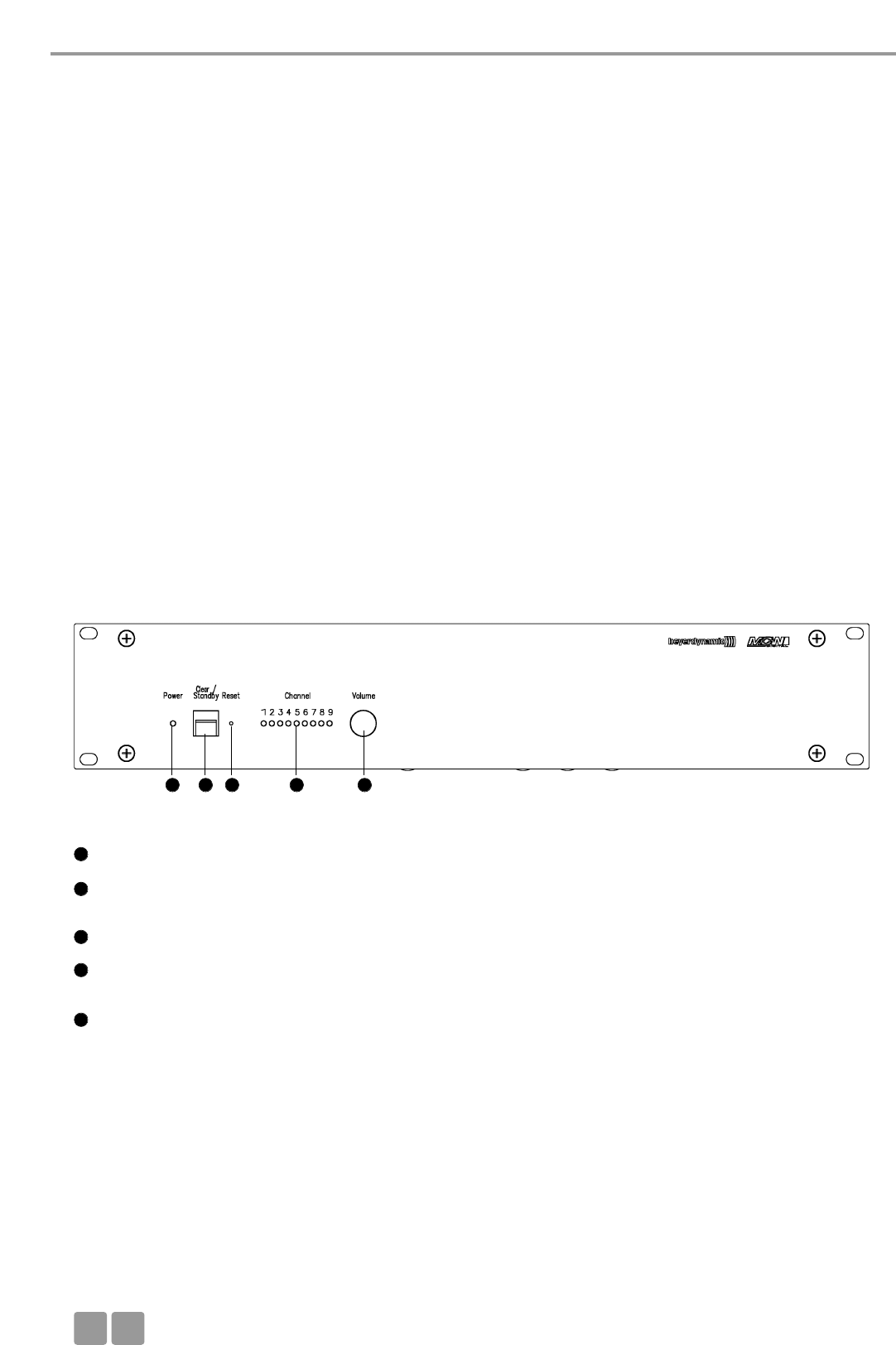
Centrale de contrôle MCW-D 50
F
54
Merci d’avoir choisi, le système de conférence sans fil MCW-D 50 et de consacrer un peu de temps à lire ce manuel avant de
mettre le système en service.
L’installation et le pilotage du système sans commande et sans configuration via un PC sont décrits dans cette notice d’utilisa-
tion.
Les composants suivants font partie de la version de base d’un système pour l’exploitation sans PC:
• Centrale de contrôle MCW-D 50
• Poste de délégué MCW-D 521
• Poste de président MCW-D 523
La centrale de contrôle MCW-D 50 est disponible en deux versions:
MCW-D 50-3 pour conférences lors desquelles jusqu’à 3 orateurs (p. ex. 2 Délégués et 1 Président) peuvent parler simultanément.
MCW-D 50-9 pour conférences lors desquelles jusqu’à 9 orateurs (p. ex. 7 Délégués et 2 Présidents) peuvent parler simultanément.
Vous trouverez de plus amples informations sur la commande et la configuration du système MCW-D 50 dans la notice d’ins-
tructions «MCW-D 50 Conference Software».
3. Centrale de contrôle MCW-D 50
La centrale de contrôle MCW-D 50 est le cœur du système. Elle permet de commander les postes de délégués et de président.
Avec la version standard du centrale de contrôle MCW-D 50 max. 3 orateurs (2 délégués et 1 président par ex) peuvent parler
simultanément.
3.1 Eléments de contrôle
Vue frontale
LED «Power»: Lorsque la LED est allumée en vert, l’appareil est sous-tension.
Bouton «Standby»: Lorsque ce bouton est appuyé pour plus de 3 secondes, tous les postes sont éteints.
Tous les microphones attribués sont déconnectés sur brève pression.
Reset: Ce bouton permet d’effectuer une remise à zéro de l’appareil. Utiliser la pointe d’un crayon.
LEDs indiquant le statu des canaux de réception. Quand une LED est allumée en vert: le canal
est libre. Quand une LED est allumée en rouge: le canal est occupé
Réglage du niveau pour haut-parleur du postes
1
1
2
3
4
5
2 3 4 5

Centrale de contrôle MCW-D 50
F55
Port RS-232 pour le raccordement à un PC ou à un media contrôleur. (Sub-D 9 broches).
Branchement réseau RLE
LED de contrôle pour alimentation antenne 5 V DC (vert = DC normal; clignote rouge rapidement = court-circuit)
Interrupteur -10 dB / +15 dB pour entrée asymétrique (RCA)
Input = Entrée, RCA, asymétrique, pour le raccordement d’appareils externes tels que lecteur de CD (L + R)
Output – Sortie audio, RCA, asymétrique, pour le raccordement d’appareils externes tels que console,
système de sonorisation externe ou enregistreur (L + R)
Réglage du niveau de sortie audio principale, RCA
Interrupteur -10 dB / +15 dB pour entrée symétrique (XLR)
Input = Entrée, XLR 3 points femelle, symétrique, pour le raccordement de sources audio externes (+6 dBm)
Output – Sortie audio, XLR 3 points mâle, symétrique, pour le raccordement d’appareils externes tels que
console ou système de sonorisation
Interrupteur Arrêt / Marche
Fusible
Prise secteur
Connecteurs pour les antennes de réception A/B
Connecteur pour l’antenne d’émission
6
7
8
9
10
10
10
11
11
12
13
14
14
15
16
17
18
19
20
Vue arrière
3.2 Installation
3.2.1 Placement de la centrale
• Si vous n’utilisez pas d’antennes déportées, placez la centrale de contrôle MCW-D 50 dans la pièce où se tient la conférence.
Avec des antennes déportées, placez les antennes dans la pièce où se tient la conférence.
• Ne placez pas la centrale de contrôle MCW-D 50 trop près d’un équipement travaillant avec un contrôleur numérique.
6 7 11 12 13 14 15 16 17 18
192019
98
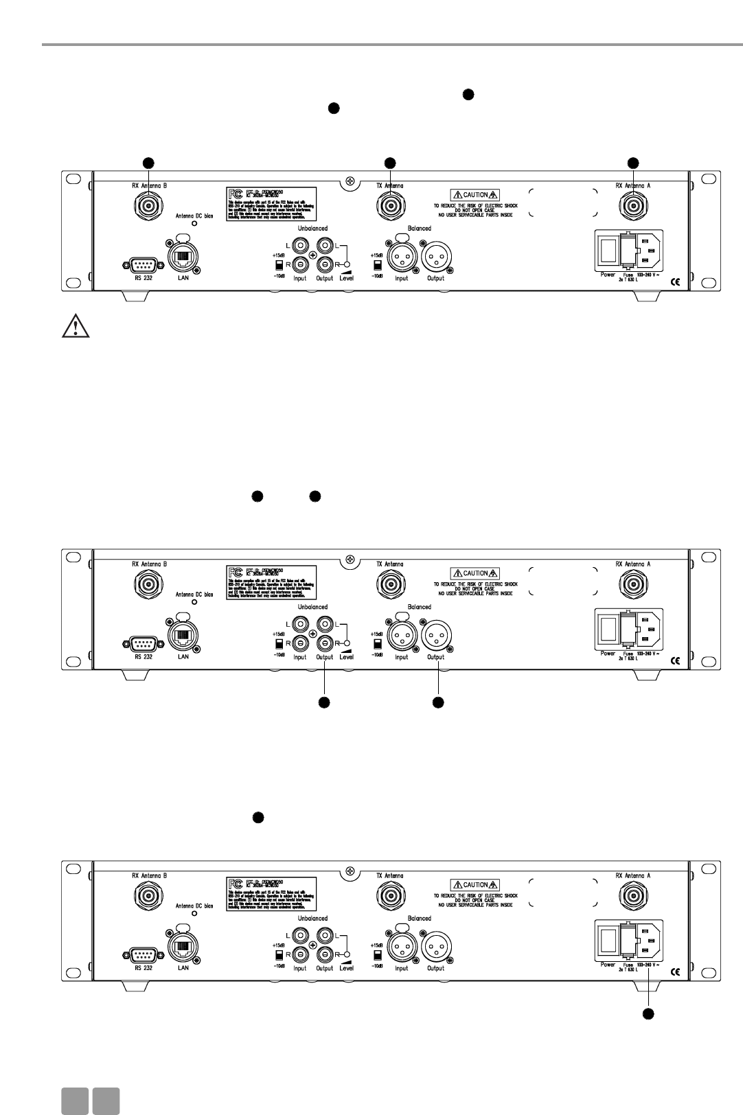
Centrale de contrôle MCW-D 50
F
56
3.2.2 Raccorder les antennes
• Raccordez les deux antennes de réception sur les entrées d’antenne A et B .
• Raccordez l’antenne de transmission sur la sortie .
Pour une installation mobile, nous vous conseillons d’utiliser une antenne souple coudée CA 2411.
3.2.3 Connexion Audio
• Raccorder la sortie principale XLR ou RCA à l’entrée de la console ou de l’amplificateur.
• Posez les câbles de façon à ce qu’ils ne soient pas courbés, voire coupés pas des objets coupants.
3.2.4 Connexion Alimentation
• Vérifiez si les puissances connectées correspondent à l’alimentation secteur existante. Un raccordement du système à la mau-
vaise alimentation en courant risque de provoquer de graves dommages.
• Posez le câble d’alimentation de façon à ce qu’ils ne soit pas courbé, voire coupé pas des objets coupants.
• Raccorder la MCW-D 50 au secteur . L’alimentation de l’unité s’adapte automatiquement à la tension alternative du secteur
entre 100 V et 240 V chez 50 - 60 Hz.
Importante:
•Entre les antennes et les postes il doit y avoir une inter-visibilitée, c’est-à-dire qu’il ne doit pas y avoir d’ob-
stacles entre la MCW-D 50 et les postes. La plage de portée est de 30 - 50 mètres environs. Pour un fonctionne-
ment optimum, la surface de la table est importante. Les tables en bois ou en plastique sont idéales, mais les tables
en métal peuvent créer des interférences et diminuer la portée.
15 11
1920
20
19
19
11 15
18
18
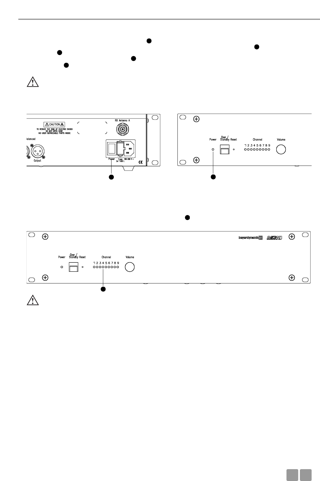
Centrale de contrôle MCW-D 50
F57
3.2.5 Mettre en marche / hors service
• Placez la MCW-D 50 sur marche avec l’interrupteur situé à l’arrière.
• La centrale de contrôle est initialisée pendant les 30 premières secondes environ et la LED «Power» ainsi que les LEDs
«Channel» clignotent rouge. Une exploitation n’est pas possible pendant ce temps. Si la centrale de contrôle MCW-D 50
est reliée à un réseau via le connecteur LAN , il s’écoulera environ 20 secondes avant qu’elle ne soit prête à fonctionner.
• La LED Power verte sur la face avant est allumée lorsque la centrale de contrôle est prête à fonctionner.
•ATTENTION: Déconnectez toujours l’alimentation de courant avant de procéder à des travaux sur les entrées et les sorties.
Vue arrière Vue frontal
3.2.6 LED indique
• Suivant la configuration de la MCW-D 50, 3 ou plus de LED de canal s’illuminent en vert ( En standard: 3 canaux).
3.2.7 Montage dans une baie 19"
• Lorsque la MCW-D 50 est montée dans une baie 19",il faut laisser au-dessus et au-dessous de MCW-D 50 une
unité de libre pour la ventilation.
3.2.8 Contrôle du volume son
• Le contrôle du niveau de volume des postes d’orateur s’effectue avec le mécanisme virtuel de réglage par le biais du logiciel
MCW-D 50 Conference.
Important:
• Si 3 LEDs au plus sont allumées pour une centrale de contrôle équipée de plus d’un module HF, veuillez vérifier si des
modules ont été séparément désactivés via le logiciel MCW-D 50 Conference.
16
1
1
7
4
4
16 1
4
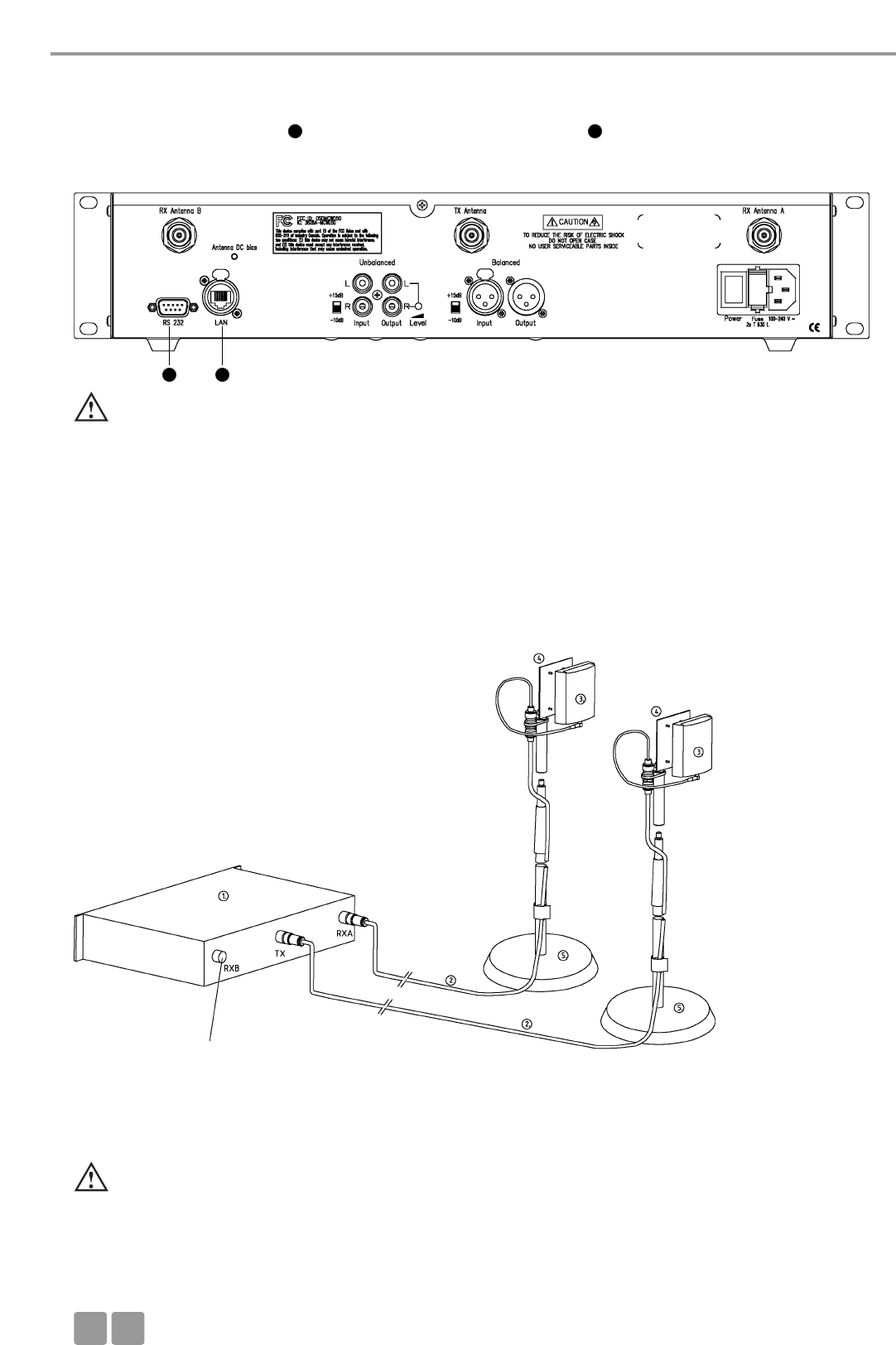
Centrale de contrôle MCW-D 50
F
58
3.2.9 Raccordement d’un media contrôleur externe et d’un PC
• Si vous souhaitez raccorder simultanément un media contrôleur externe et un PC à la centrale de contrôle MCW-D 50, raccordez
le PC au connecteur réseau LAN et le media contrôleur externe au port RS 232 .
• Pour le raccordement direct du connecteur LAN à un PC, vous devez utiliser un câble «crossover».
• Les réglages LAN sont expliqués dans le protocole du logiciel MCW-D 50 Conference.
3.3 Raccordement et placement des antennes déportées
L’unité centrale MCW-D 50 peut aussi fonctionner avec des antennes déportées. Des câbles à faible perte en différentes lon-
gueurs sont disponibles en option. Il est à noter que les trois antennes doivent être déportées. L’antenne de transmission doit
être monté au centre et les antennes de réception à droite et à gauche. La plage de fonctionnement peut être augmenté en
utilisant l’antenne unidirectionnelle CA 2413, gain de +6 dB approximativement.
Suivant l’atténuation du câble, vous devez utiliser un amplificateur d’antenne en fonction de la longueur de celui-ci.
L’antenne plane CA 2413 est raccordée à la centrale de commande MCW-D 50 et fixée sur le pied avec le kit de montage
CA 2462. Vous trouverez d’autres possibilités d’installation dans notre «Guide design MCW-D».
Exemple de montage variable avec des antennes décalées
Importante:
•Entre les antennes et les postes il doit y avoir une inter-visibilitée, c’est-à-dire qu’il ne doit pas y avoir d’ob-
stacles entre la MCW-D 50 et les postes. La plage de portée est de 30 - 50 mètres environs. Pour un fonctionne-
ment optimum, la surface de la table est importante. Les tables en bois ou en plastique sont idéales, mais les tables
en métal peuvent créer des interférences et diminuer la portée.
6 7
7 6
(1) Centrale de commande MCW-D 50
(2) Câble d’antenne CA 2421/2422 ou
CA 2431/2432
(3) Antenne plane CA 2413
(4) Kit de montage 3/8" CA 2462
(5) Pied stand 3/8" ST 600
comme RX A
Important:
• Ne manipulez jamais simultanément la centrale de contrôle MCW-D 50 avec le media contrôleur et le logiciel
MCW-D 50 Conference. Le bon fonctionnement du système pourrait en être affecté.
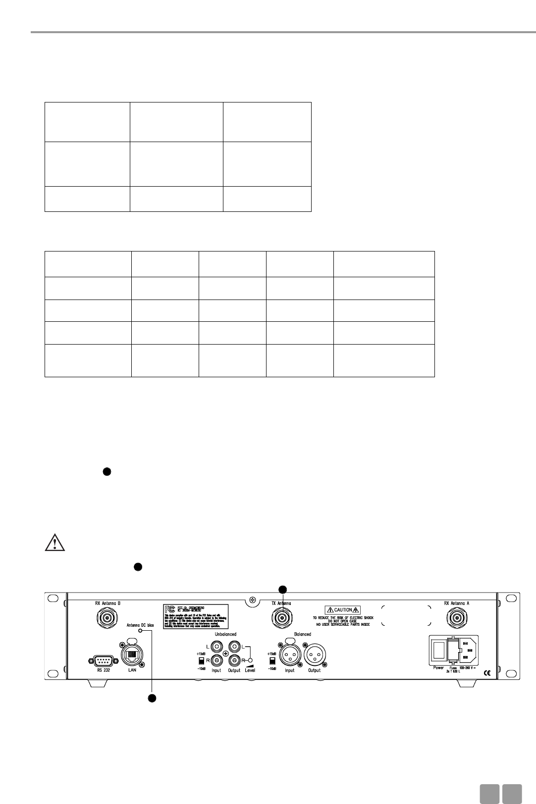
Centrale de contrôle MCW-D 50
F59
3.4 Téléalimentation des amplificateurs de signaux d’antenne via la centrale
Les amplificateurs de signaux d’antenne peuvent être téléalimentés via la centrale. A l’intérieur de la centrale se trouve une
LED diagnostic que l’on peut voir par la fente d’aération, sur la face arrière.
Cette LED est verte si la tension de téléalimentation est de 5 V sur toutes les prises d’antenne.
La LED clignote rouge rapidement si un court-circuit survient sur une prise d’antenne. Vérifiez dans ce cas le câblage d’antenne.
La tension de téléalimentation de 5 V sert à l’alimentation des amplificateurs de signaux d’antenne CA 2441 RT et CA 2441 T.
• Surface de la salle: 400 m2 max. (20 x 20)
• Nombre de participants: 30 à 100
• Position de l’antenne: Au bord de la position assise des participants, dans la mesure du possible au-dessus du
niveau de la table
• Orientation: Orienter les antennes en direction des participants (côté convexe vers l’avant)
Nous recommandons d’utiliser l’amplificateur d’antenne CA 2441 si l’atténuation du câble excède 12 ou 15 dB, c’est-à-dire si la
longueur du câble CA 2420 est supérieure à 40 m, ou si la longueur du câble CA 2430 est supérieure à 60 m.
Atténuation de différents câbles suivant l’application.
Câble
Longueur du câble 100 m 50 m 30 m
RG 58 100 dB 50 dB 30 dB inapproprié
RG 213 U 49 dB 24 dB 15 dB longueur câble:
uniquement courte
Aircell 7, CA 2420 41 dB 20 dB 12 dB longueur câble:
moyenne
Ecoflex 10, CA 2430 24 dB 12 dB 7 dB longueur câble: longue
Aircell 7
Standard
CA 2420
Ecoflex 10
Low Attenuation
CA 2430
Longueur de
câble max.
20 m max.
= 1 x CA 2422
ou 2 x CA 2421
40 m max
Rayon de courbu-
re min. 25 mm 40 mm
ATTENTION:
• Les amplificateurs de signaux d’antenne CA 2441 RT et CA 2441 T ne peuvent fonctionner que sur du 5 V CC.
• Un câble de raccordement d’une atténuation de 10 dB min. doit être utilisé en cas de branchement d’un CA 2441 RT
à la sortie TX du MCW-D 50.
8
20
20
8

Postes d’orateurs
F
60
4. Postes Délégué et postes Président
• Au départ usine, chaque poste est programmé avec une adresse différente (numéro de série), de sorte à ce que l’unité
centrale MCW-D 50 puisse communiquer correctement avec chacun d’entre eux. Ce numéro est inscrit sous le poste.
• Dans le protocole de transmission, chaque poste est appelé par radio par le biais d’un numéro ID propre. Ce numéro peut
être modifié à l’aide du logiciel MCW-D 50 Conference. A la livraison, le numéro d’identification correspond aux quatre der-
niers chiffres du numéro de série.
• Si vous commandez par la suite d’autres postes, informez votre distributeur ou beyerdynamic du type et du nombre de pos-
tes que vous possédez déjà avec leurs numéros de série pour qu’il n’y ait pas de doublons.
4.1 Postes d’orateurs MCW-D 521 / 523
4.1.1 Eléments de contrôle
Important:
• Les contacts de charges des postes peuvent causer des dommages, des blessures ou créer des incendies s’ils viennent
en contact avec des matériaux conducteurs tels que des bijoux, des clefs ou des chaînes. Ceci peut créer un court-cir-
cuit et faire chauffer le poste.
•Pour éviter un étirement et une usure prématurée, ajuster toujours le col de cygne du microphone en uti-
lisant la partie flexible base et jamais la tête du microphone ou le tube rigide. Eviter un ajustement plus
de 90°.
• Si vous souhaitez faire fonctionner les postes d’orateur au moyen d’une alimentation externe, veuillez à cet effet
exclusivement employer l’alimentation/le chargeur CA 2457.
Bornes de chargement pour CC 10, CD 10
Connecteur DC pour les postes alimentés en continu DC et pour charger
LED de fonctionnement (verte / rouge)
Mini Jack stéréo (3,5 mm) pour le raccordement d’enregistreur ou
d’écouteur (DT 1)
Vue arrière
Col-de-cygne avec anneau lumineux
Haut-parleur
LED d’état (Verte / Rouge)
Bouton Microphone
Vue de dessus poste déléguée MCW-D 521
1
1
2
3
4
5
6
7
8
234
5
6
7
8
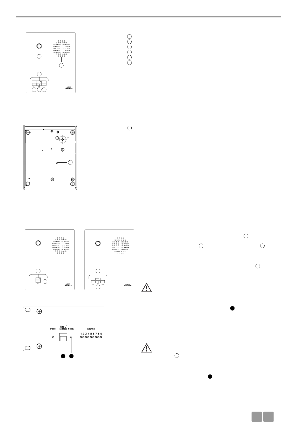
Postes d’orateurs
F61
Col-de-cygne avec anneau lumineux
Haut-parleur
LED d’état (Verte / Rouge)
Bouton Microphone
Bouton Clear, pour couper les postes délégués
Bouton de fonction (voir chapitre 6.2)
Vue de dessus poste président MCW-D 523
4.1.2 Mettre en marche / mettre hors-circuit
Poste déléguée Poste président Mettre en marche
•Les postes n’ont pas d’interrupteur Arrêt / Marche. Ils sont allu-
més et éteints en utilisant le bouton microphone .
• En appuyant brièvement sur le bouton microphone, le poste
est mis en marche. La LED clignote en rouge et la LED
située à l’arrière s’illumine.
Mettre hors-circuit
• En appuyant sur le bouton plus de 2 secondes la LED s’illu-
minera deux fois de vert à rouge brièvement, puis le poste sera
arrêté.
• Si vous appuyez sur le bouton de Stand By plus de 3 secon-
des, vous éteindrez tous les postes MCW-D qui sont allumés et à
portée de l’unité centrale MCW-D 50.
• Cependant, les postes sont automatiquement arrêtés s’ils ne
reçoivent pas de données depuis l’unité centrale MCW-D 50 pen-
dant plus de 3 minutes.
Important:
• Si un poste est hors de portée de l’unité centrale MCW-D 50,
la LED clignote en rouge. Après 3 minutes, le poste
est automatiquement arrêté.
• Si le système ne fonctionne pas, par exemple un poste
est en marche, mais qu’aucun son n’est entendu, appuyer
sur le bouton de remise à zéro de l’unité centrale
MCW-D 50. Si le système ne fonctionne toujours pas,
vérifiez la configuration avec le logiciel MCW-D 50
Conference. Si le système ne fonctionne toujours pas,
veuillez contacter votre distributeur beyerdynamic.
5
6
6
7
7
7
3
8
9
5
7
89 10
8
8
10
Touche Reset noyée
Vue de dessous MCW-D 521 / MCW-D 523
11
8
7
2
2
3
3
Important:
• La mise hors tension manuelle du poste peut être
désactivée avec le logiciel MCW-D 50 Conference.
7 7
11
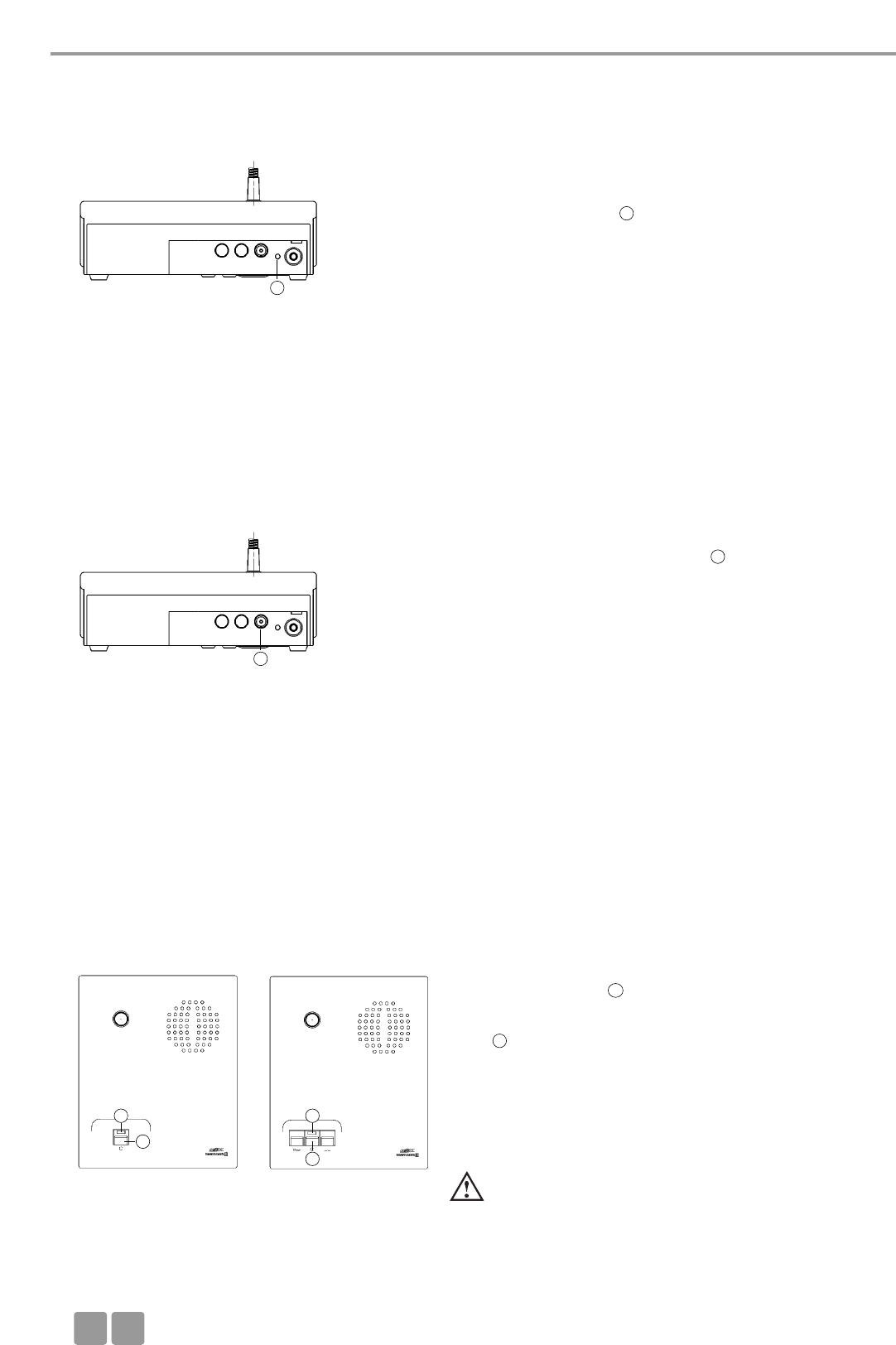
Installation
F
62
4.2 Alimentation / Autonomie
• Les postes sont équipées d’un accumulateur interne qui leur procure
environ 20 heures d’autonomie.
• Dès que la capacité est trop faible pour assurer un fonctionnement cor-
rect, la LED de fonctionnement clignotera. Le temps de fonctionne-
ment restant est d’environ 60 minutes.
• Le déchargement progressif des accus des postes d’orateur peut être
affiché sur un PC raccordé à la centrale de contrôle MCW-D 50 au
moyen du logiciel MCW-D 50 Conference fourni. Cet affichage est éga-
lement possible via un media contrôleur externe raccordé à la centrale
de contrôle MCW-D 50.
Vue arrière poste
4.3 Alimentation externe CA 2457
• Les postes MCW-D peuvent être alimentées par l’alimentation externe
CA 2457, qui doit être raccordé au connecteur .
• Lorsque l’alimentation est branchée, le poste est également chargé. Cf.
Chapitre 8. Recharge des accus par alimentation externe.
Vue arrière poste
4.4.1 Mode Normal
• Appuyer sur le bouton pour activer ou désactiver le microphone.
• La bague rouge sur le col-de-cygne
du microphone s’illumine et la
LED s’illumine en vert: Le poste est prêt pour la discussion.
• Avec l’unité centrale MCW-D 50-3, 3 participants (par ex. 2 délé-
gués et 1 président) peuvent parler simultanément. Avec l’unité
centrale MCW-D 50-9, 9 participants maximum (8 délégués et un
président par ex.) peuvent parler simultanément.
Important:
• Si le nombre maximum de Poste actif est atteint,
un poste ne peu prendre la parole manuellement
que si un des postes actifs est coupé.
Poste déléguée Poste président
3
3
2
2
8
7
7
8
8
7
4.4 Modes de fonctionnement
• Les différents modes de fonctionnement tels que Manuel, Push-To-Talk ou Parole sont réglés à l’aide du logiciel MCW-D 50
Conference. Le mode de fonctionnement standard au départ usine est le mode Normal. Veuillez vous reporter à cet effet à la
notice d’utilisation du logiciel MCW-D 50 Conference.
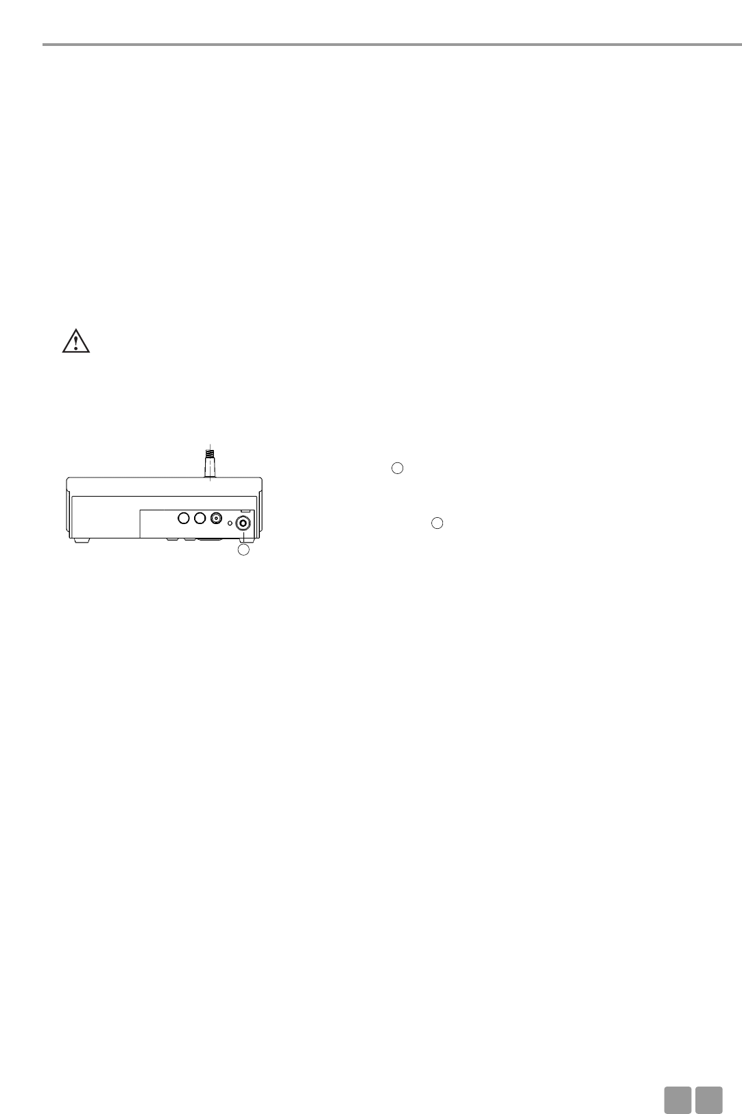
Installation
F63
4.5 Enregistrement de la conférence
• Pour enregistrer la conférence, vous pouvez raccorder un enregistreur à
la sortie .
• Le niveau de sortie peut être ajusté avec un PC et le logiciel MCW-D 50
Conference.
• À la place d’un enregistreur, un écouteur peut être raccordé à la sortie
documentation . Nous recommandons une impédance minimale de
600 Ohms. Des impédances plus faibles n’endommagent certes pas le
poste d’orateur. Elles peuvent néanmoins se révéler néfastes pour le
fonctionnement sur casque.
4.6 Maintenance des postes MCW-D
• Pour le nettoyage des postes MCW-D quand ils sont très peu sales (trace de doigt, poussière, nourriture), utiliser un chiffon
doux humide, une éponge ou une brosse et un produit de nettoyage liquide.
• Avant de nettoyer la surface, elle doit être dépoussiéré profondément. Bien dépoussiérer la surface, puis nettoyer avec un
chiffon humide.
• Assurez vous qu’aucun liquide ne pénètre dans les transducteurs.
• Pour les taches d’huile ou de graisse, utiliser du white-spirit, de l’alcool isopropyl ou du benzène.
• Pour les traces d’encre ou de papier carbone, utiliser du white-spirit, ou de l’alcool isopropyl.
• Nettoyez de temps en temps les contacts de charge à l’alcool ou à l’alcool isopropyle.
• Nettoyez la bonnette anti-vent avec de l’eau claire. Assurez vous qu’elle soit complètement sèche avant de la replacer sur le
microphone.
4.4.2 Mode FiFo
• Si les postes orateurs opèrent en mode FiFo, le poste orateur connecté en premier est déconnecté en connectant un autre
poste orateur lorsque le nombre maximal de microphones ouverts (NOM) est dépassé.
4.4.4 Mode contrôle vocal
• Si les postes orateurs opèrent en mode contrôle vocal, les postes orateurs sont connectés dès que l’on parle dans le micropho-
ne. Dans ce cas, on n’a pas recours à la touche du microphone.
Important:
• Le seuil de réponse peut être configuré séparément pour chaque poste orateur avec le logiciel Conference MCW-D 50.
Egalement le temps «Hold».
4
4
4
4.4.3 Mode Push-To-Talk
• Lorsque les postes travaillent en mode Push-To-Talk (PTT), la touche de fonction doit être pressée aussi longtemps que l’ora-
teur parle dans le microphone. Cette configuration est par exemple recommandée lors d’une courte intervention au cours de
la conférence.
5. Fonctions poste orateur programmables avec le logiciel MCW-D 50 Conference
Les fonctions poste orateur mentionnées ci-dessous ne sont disponibles que si elles ont été programmées au préalable avec le
logiciel MCW-D 50 Conference. Pour une description plus détaillée, se reporter à la notice d’instruction du logiciel MCW-D 50
Conference.
5.1 Code Secret / Chiffrement
En utilisant le logiciel MCW-D 50 Conference, un code secret peut être entré dans les postes et dans l’unité centrale MCW-D 50
d’un même ensemble. Ceci permet d’augmenter la protection contre les écoutes non autorisées. Les postes ne disposant pas de
ce code ne sont pas identifiés par la centrale de contrôle et sont coupés.
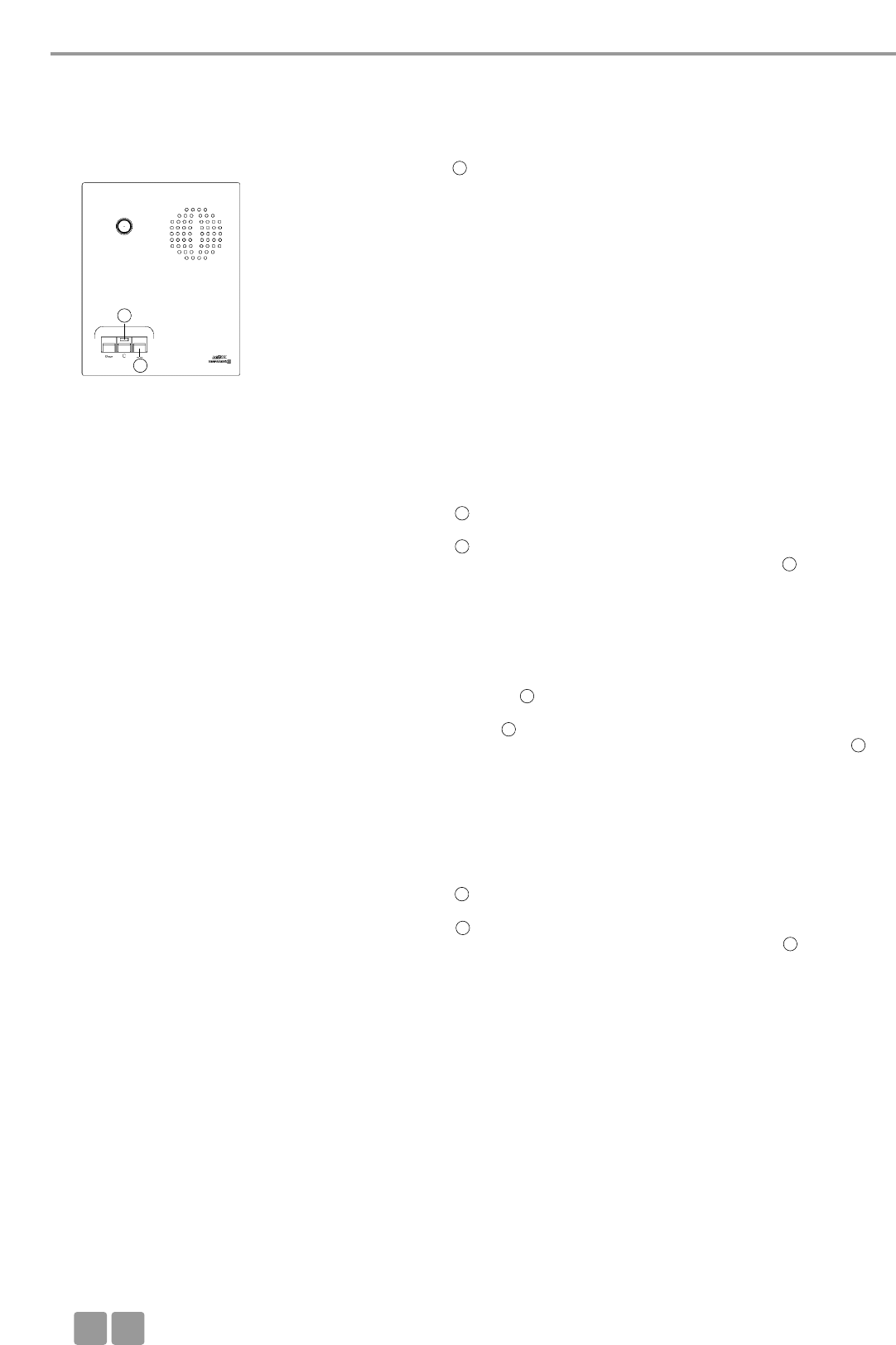
Installation
F
64
5.2 Bouton de fonction de poste président MCW-D 523
Suivant la configuration, les fonctions suivantes sont disponibles pour le
bouton : Mute, Clear ou Priorité. La fonction du bouton peut être confi-
guré avec l’unité centrale et le logiciel MCW-D 50 Conference.
1. Priorité
Tous les postes délégués seront coupés et le microphone du président
sera activé. Les Délégués ne pourront rallumer leur microphone qu’un
fois le mode Priorité terminé.
2. Mute
Tous les postes délégués qui étaient actifs seront coupés pendant que
le Président parlera et seront réactivés quand le Président relâchera le
bouton.
3. Clear
Tous les postes délégués sont coupés et kpeuvent ensuite rallumer leur
microphone.
4. Désactivation d’un raccordement externe AUX-In
Le raccordement est désactivé en appuyant une fois sur la touche de
fonction. La désactivation est supprimée en appuyant une deuxième
fois sur la touche de fonction. Le raccordement est de nouveau désac-
tivé en appuyant une troisième fois sur la touche de fonction, etc.
Lorsque le Président appuie à son poste sur la touche de fonction, l’en-
trée Aux sur la centrale de contrôle MCW-D 50 est coupée. Le témoin
LED situé au-dessus de la touche de microphone clignote en rouge
(lentement). Lorsque le Président allume son microphone, le témoin
LED clignote en vert (lentement). Lorsque la Priorité est désactivée
et que le microphone est toujours allumé, le témoin LED est allumé
en vert.
5. Désactivation du raccordement symétrique AUX-In et suppression
de tous les postes de délégués actifs. La désactivation est supprimée en
appuyant une deuxième fois sur la touche de fonction. Le raccorde-
ment est de nouveau désactivé en appuyant une troisième fois sur la
touche de fonction et tous les postes Délégués actifs sont supprimés
etc.
Le témoin LED situé au-dessus de la touche de microphone clignote
en rouge (lentement). Lorsque le Président allume son microphone, le
témoin LED clignote en vert (lentement). Lorsque la Priorité est
désactivée et que le microphone est toujours allumé, le témoin LED
est allumé en vert.
6. Désactivation d’un raccordement externe AUX-Out
Le raccordement est désactivé en appuyant une fois sur la touche de
fonction. La désactivation est supprimée en appuyant une deuxième
fois sur la touche de fonction. Le raccordement est de nouveau désac-
tivé en appuyant une troisième fois sur la touche de fonction, etc.
Lorsque le Président appuie à son poste sur la touche de fonction, la
sortie Aux sur la centrale de contrôle MCW-D 50 est coupée. Le témoin
LED situé au-dessus de la touche de microphone clignote en rouge
(lentement). Lorsque le Président allume son microphone, le témoin
LED clignote en vert (lentement). Lorsque la Priorité est désactivée
et que le microphone est toujours allumé, le témoin LED est allumé
en vert.
7. Fonction «COM Message»
Une commande est envoyée par l’interface série RS 232 de l’unité cen-
trale MCW-D 50, et une fonction est exécutée par un media Contrôleur
par exemple (Commande de la lumière).
Pour les autres fonctions il y a aussi une commande envoyée par l’in-
terface série RS 232 de l’unité centrale MCW-D 50.
8. Fonction «Custom»
Deux commandes différentes en fonction de la durée de pression sur
la touche de fonction
< 1 seconde = commande «Short press string» est transferée
> 1 seconde = commande «Long press string» est transferée
Ces commandes peuvent être réglées à l’aide du logiciel MCW-D 50
Conference en fonction des besoins du client.
Poste président
10
10
7
7
7
7
7
7
7
7
7
7

Installation
F65
6. Chargeur CD 10 dans chariot CC 10
• Avec le chargeur CD 10, inclus dans le chariot de transport CC 10, il est possible de charger un maximum de 10 postes à la
fois. L’état de charge des accumulateurs peut être vu depuis l’extérieur sur la fenêtre d’affichage.
• Le chariot de transport CC 10 peut à tout moment être complété par des unités de chargement CD 10 supplémentaires pou-
vant chacune contenir 10 accus de postes d’orateur.
• Le chargeur CD 10 dispose d’un compartiment de rangement pour les accessoires tels que casque.
6.1 Première utilisation
Pour que les accumulateurs est une capacité de 100 %, chaque poste doit effectuer au moins deux cycles complet de charge et
de décharge. Ce n’est seulement qu’après plusieurs cycles de charge et de décharge que les accumulateurs obtiennent leur
capacité maximum.
5.3 Mode Demande de parole
• Ce mode n’est possible qu’avec l’utilisation d’un PC et le logiciel
MCW-D 50 Conference ou d’un media contrôleur externe. (AMX®,
Crestron®, Cue etc.).
• La demande de parole est enregistrée dans le système en appuyant sur
le bouton microphone d’une poste.
• L’autorisation est donné par l’opérateur sur le PC ou sur l’écran tactile
du media contrôleur.
• La LED s’illumine en vert pour indiquer la demande de parole.
• Si vous appuyez de nouveau sur le bouton , vous annulez la demande
de parole. La LED s’éteint.
Poste déléguée
6.2 Processus de charge
1. Raccorder le chargeur au secteur et mettez-le sur marche. La LED de l’interrupteur s ‘allume.
2. Placez les postes d’orateurs éteints dans les compartiments de charge. Si les postes sont allumés, ils seront automatique-
ment éteints. Pour utiliser de nouveau les postes, il faudra les rallumer.
3. Le processus de charge est indiqué par la LED du col de cygne et est visible de l’extérieur sur la fenêtre d’affichage.
Affichage LED durant le processus de charge de l’accumulateur:
a) LED col de cygne clignote en rouge. . . . . . . . . . . . . . . . . . . . . Accumulateur en charge
b) LED col de cygne allumée constamment en rouge . . . . . . . . . Accumulateur complètement chargé
c) LED col de cygne clignote rapidement en rouge . . . . . . . . . . . Erreur
Note
• Si une erreur a lieu, essayer de redémarrer le processus de charge de nouveau. Si les LEDs continuent de clignoter
rapidement, contactez votre revendeur.
• Le temps de recharge est d’environ 2 heures quand les accumulateurs sont complètement vide.
• Avec le temps, la capacité des accus diminue. Le temps de fonctionnement s’en trouve raccourci.
• Il est normal que les accumulateurs soient chauds pendant l’opération de recharge.
• Nettoyez de temps en temps les contacts de charge à l’alcool ou à l’alcool isopropyl.
7
8
8
7
7
8
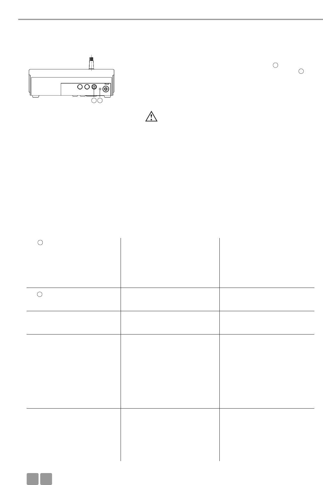
Dépannage
F
66
7. Recharge des accus par alimentation externe
• Les postes MCW-D peuvent également être rechargés avec l’alimentation
externe CA 2457 qui sera raccordée au connecteur DC .
• Le processus de charge est indiqué par la LED de fonctionnement .
Affichage LED durant le processus de charge de l’accumulateur:
a) LED clignote en rouge . . . . . . . . . . . . . . . . . Accumulateur en charge
b) LED allumée constamment en rouge . . . . . . Accumulateur
complètement chargé
c) LED clignote rapidement en rouge. . . . . . . . Erreur
Vue arrière
Important:
• Avec le temps, la capacité des accus diminue. Le temps de
fonctionnement s’en trouve raccourci.
•Il est normale que les accumulateurs chauffent durant le
processus de recharge.
• Le temps de recharge est d’environ 5 heures quand les
accumulateurs sont complètement vide.
• Si le poste est mis sous tension durant le processus de recharge,
le témoin LED est allumé en vert.
8. Dépannage
En cas de problèmes avec les postes orateurs qui se sont pas listés dans le tableau suivant, il convient d’abord de régler le système
MCW-D 50 sur la configuration standard à l’aide du logiciel MCW-D 50 Conference. Cf. la notice d’instruction correspondante.
Problème
LED clignote rouge rapidement
LED clignote
Poste opérateur s’éteint
Assignation non possible
Poste orateur ne peut pas être connecté
Cause éventuelle
• La centrale de commande n’est pas
branchée
• Le rayon d’action est dépassé
• Bandes de fréquences mal configurés
• Accu presque vide
• Seuil d’alarme temps restant accu
affiche que l’accu est presque vide
• Vérifiez si l’accu est encore plein
• Code PIN est activé
• Tous les canaux sont occupés
• Vérifiez le réglage NOM avec le logi-
ciel MCW-D 50 Conference
• Le rayon d’action est dépassé
• Vérifiez les réglages de bandes de
fréquences
• Perturbation par WLAN
• Centrale de commande n’est pas
branchée
• Vérifiez le réglage NOM avec le logi-
ciel MCW-D 50 Conference
• Vérifiez l’accu
• Le rayon d’action est dépassé
Solution
• Branchez la centrale de commande
• Diminuez la distance entre la centra-
le de commande et les postes d’ora-
teurs
• Vérifiez les réglages de bandes de
fréquences avec le logiciel MCW-D
50 Conference
• Rechargez le posteorateur
• Si l’accu est vide, rechargez le poste
orateur
• Désactivez le code PIN
• Eteignez un microphone actif
• Si possible,augmentez le NOM avec
le logiciel MCW-D 50 Conference
• Diminuez la distance entre la centra-
le de commande et les postes ora-
teurs
• Utilisez les réglages standard men-
tionnés dans la notice d’instruction
MCW-D 50 Conference
• Sélectionnez via le logiciel MCW-D
50 Conference une autre bande de
fréquence pour le/les module(s) HF
• Branchez la centrale de commande
• Si possible, augmentez le NOM
• Si l’accu est vide, rechargez le poste
orateur
• Diminuez la distance entre la centra-
le de commande et les postes ora-
teurs
2
2
3
3
7
3

Dépannage
F67
Cause éventuelle
• Vérifiez le réglage de volume avec le
logiciel MCW-D 50 Conference
• Mise hors tension manuelle désactivée.
• Mode de fonctionnement Push-To-
Talk ou Parole est activé
• Microcontrôleur du poste est bloqué
• Poste orateur n’est pas branché
• Casque n’est pas raccordé correcte-
ment
• Vérifiez le réglage de volume avec le
logiciel MCW-D 50 Conference
• Vérifiez les haut-parleurs externes
• Vérifiez le niveau audio
• Le rayon d’action est dépassé
• Vérifiez la position d’antenne et le
câble d’antenne
• Vérifiez le contact visuel entre le
poste orateur et l’antenne
• Perturbations par des appareils
tels que Wireless LAN
Solution
• Augmentez le volume par le biais du
logiciel MCW-D 50 Conference ou
avec le réglage du niveau de la cen-
trale de contrôle MCW-D 50
• Activez la fonction «Mise hors
tension manuelle» via le logiciel
MCW-D 50 Conference
• Désactivez le mode Push-To-Talk ou
Parole dans le logiciel MCW-50
Conference
• Eteignez les postes depuis la centrale
de contrôle en pressant plus de 3
secondes sur la touche Clear/Veille
• Eteignez la centrale de contrôle, au
bout de 3 minutes env. les postes s’é-
teignent
• Appuyez sur la touche Reset noyée
située sous le poste
• Branchez le poste orateur
• Raccordez le casque correctement
• Augmentez le volume avec le logi-
ciel MCW-D 50 Conference ou avec
le réglage de volume sur la centrale
de contrôle MCW-D 50
• Corrigez le volume et la position des
haut-parleurs
• Diminuez le niveau d’entrée à la
centrale de commande
• Diminuez la distance entre la centra-
le de commande et les postes ora-
teurs
• Si nécessaire, utilisez un amplifica-
teur de signaux d’antenne
• Eliminez tout obstacle entre les pos-
tes orateurs et les antennes; ne rien
placer devant les antennes de la cen-
trale de commande
• Sélectionnez via le logiciel
MCW-D 50 Conference une autre
bande de fréquence pour le/les
module(s) HF. Cf. Chapitre 8.1.
Problème
Haut-parleur poste orateur ne fonc-
tionne pas
Le poste ne peut être éteint
La sortie documentation ne fonctionne
pas
Rétroactions
Parasites
Brefs ratés
8.1 Utilisation simultanée du système de conférence MCW-D avec d’autres appareils
2,4 GHz (p. ex. WLAN, Bluetooth)
8.1.1 Fondements physiques
En vertu de lois physiques, un fonctionnement simultané sans perturbations de plusieurs appareils utilisant la même bande de
fréquence ne saurait être garanti. Les appareils radio opérant sur la même bande de fréquence sont invariablement soumis à
une influence et une perturbation réciproques (ce qui le cas échéant peut entraîner des disfonctionnements).
L’exemple des liaisons UHF telles que les microphones sans fil le montre clairement. Il est ici notoire que 2 liaisons UHF ne peu-
vent jamais fonctionner simultanément avec la même fréquence porteuse. Au stade actuel de la technique, seul un nombre
déterminé de liaisons compatibles est à même d’être utilisé au sein d’une même plage de fréquence.
La bande ISM à 2,4 GHz (2400 MHz - 2484 MHz) est soumise à des lois analogues. En raison de procédés de transmission numéri-
ques et de différents standards de transmission, le fonctionnement simultané de certains appareils sur une même bande de fré-
quence est certes possible avec des restrictions, mais non recommandable.
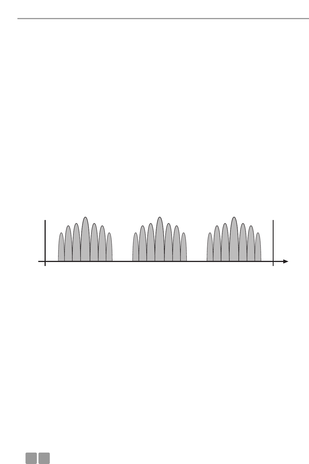
Dépannage
F
68
Utilisation de fréquence MCW-D 50 / WLAN
MCW-D 50 WLAN
Canal . . . . . . . . . . . . . . . . . . . Fréquence centrale Canal . . . . . . . . . . . . . . . . . . . Fréquence centrale
Low . . . . . . . . . . . . . . . . . . . . 2412 MHz 1 . . . . . . . . . . . . . . . . . . . . . . . 2412
2 . . . . . . . . . . . . . . . . . . . . . . . 2417
3 . . . . . . . . . . . . . . . . . . . . . . . 2422
4 . . . . . . . . . . . . . . . . . . . . . . . 2427
5 . . . . . . . . . . . . . . . . . . . . . . . 2432
Mid. . . . . . . . . . . . . . . . . . . . . 2438 MHz 6 . . . . . . . . . . . . . . . . . . . . . . . 2437
7 . . . . . . . . . . . . . . . . . . . . . . . 2442
8 . . . . . . . . . . . . . . . . . . . . . . . 2447
9 . . . . . . . . . . . . . . . . . . . . . . . 2452
10 . . . . . . . . . . . . . . . . . . . . . . 2457
High . . . . . . . . . . . . . . . . . . . . 2464 MHz 11 . . . . . . . . . . . . . . . . . . . . . . 2462
12 . . . . . . . . . . . . . . . . . . . . . . 2467
13 . . . . . . . . . . . . . . . . . . . . . . 2472
14 . . . . . . . . . . . . . . . . . . . . . . 2484
On constate aisément que les canaux WLAN, en raison de leur largeur de bande, se chevauchent fortement. Tous les canaux voi-
sins (p. ex. canal 1 & 2 ou canal 7 & 8) ne sont pas utilisables simultanément, ils seraient soumis à des perturbations réciproques.
A ceci s’ajoute qu’aux Etats-Unis, les canaux 12 et 13 ne sont pas autorisés. La pratique montre que ces canaux ne sont ainsi
généralement pas employés. Au sein de la bande de fréquence restante, seuls les canaux WLAN 1, 6 et 11 ne se chevauchent
pas et sont ainsi utilisables parallèlement. C’est cette utilisation de canaux qui s’est établie en pratique.
Les canaux WLAN 1, 6 et 11 ont par conséquent été choisis pour les canaux HF Low, Mid et High utilisés par le système de con-
férence MCW-D 50. Cette compatibilité fréquentielle permet un accord du système de conférence avec WLAN.
Par une planification de fréquence et une observation de la discipline de fréquence minutieuses, il est possible d’utiliser en
parallèle à proximité immédiate une centrale de contrôle MCW-D 50-3 avec plus de 4000 postes d’orateur et jusqu’à deux liai-
sons WLAN.
Autres conseils pour l’installation
• Il est recommandé d'observer une distance minimum d'env. 5 m entre les appareils avec WLAN ou Wi-Fi (p. ex. routeur, répé-
teur) et les antennes d’émission et de réception de la centrale de contrôle MCW-D 50.
• Sur les ordinateurs portables, ils est recommandé de désactiver si possible toutes les interfaces WLAN utilisant la même plage
de fréquence que MCW-D 50.
• Les canaux HF utilisés pour la circulation de données WLAN ou Wi-Fi ainsi que ceux employés pour MCW-D 50 doivent en
principe se situer autant qu’il se peut éloignés les uns des autres.
• Les canaux à utiliser pour le système de conférence MCW-D 50 peuvent être aisément sélectionnés via le logiciel MCW-D 50
Conference fourni.
8.1.3 MCW-D 50 et Bluetooth
• A l’inverse des appareils WLAN et de MCW-D 50, les appareils avec transmission Bluetooth utilisent l’ensemble de la bande
2,4 GHz du fait d’une fréquence porteuse sans cesse changeante («Frequency Hopping»).
• Grâce à diverses mesures constructives appliquées au système MCW-D 50 ainsi qu’à un protocole de transmission avancé, les
2400 MHz Low Mid High 2484 MHz
Fréquence /
MHz
8.1.2 MCW-D et WLAN ou Wi-Fi
La transmission HF du système MCW-D 50 s’oriente sur le standard WLAN, c’est-à-dire que MCW-D 50 utilise, tout comme
WLAN, une largeur de bande d'environ 22 MHz pour chaque canal HF (Low, Mid, High). Une séparation idéale des canaux étant
impossible, il en résulte pour les deux technologies trois canaux HF compatibles et ne se chevauchant pas au sein de la bande
ISM 2,4 GHz. Ces dernières sont théoriquement les suivantes :
Canal 1 compatible: 2400 MHz - 2428 MHz (fréquence centrale théorique 2414 MHz)
Canal 2 compatible: 2428 MHz - 2456 MHz (fréquence centrale théorique 2442 MHz)
Canal 3 compatible: 2456 MHz - 2484 MHz (fréquence centrale théorique 2470 MHz)
Avec les canaux HF réglables Low, Mid et High, le système MCW-D 50 utilise exclusivement des plages de fréquence compatibles
et ne se chevauchant pas. Pour WLAN, il revient aux utilisateurs de configurer eux-mêmes des canaux HF compatibles entre eux.

Accessoires
F69
10. Accessoires
Accessoire livré
1 cordon secteur
1 câble modem neutre série
MCW-D 50 Logiciel MCW-D 50 Conference, y compris version de base contrôleur pour
5 postes max. . . . . . . . . . . . . . . . . . . . . . . . . . . . . . . . . . . . . . . . . . . . . . . . . . . . . . . . Art. N° 480.274
Note:
Aucune antenne n’est livrée avec l’unité centrale.
Accessoires en Option
CA 2411 Antennes tige à angle droit, 2,4 GHz, connecteur N . . . . . . . . . . . . . . . . . . . . . . . . . Art. N° 464.236
CA 2412 Antenne tige, 2,4 GHz, connecteur SMA . . . . . . . . . . . . . . . . . . . . . . . . . . . . . . . . . . Art. N° 464.244
CA 2413 Antenne plate, 2,4 GHz, connecteur SMA . . . . . . . . . . . . . . . . . . . . . . . . . . . . . . . . . Art. N° 464.252
CA 2420 Câble standard, 2,4 GHz, vendu au mètre, connecteur N. . . . . . . . . . . . . . . . . . . . . . Art. N° 464.260
CA 2421 Câble standard, 2,4 GHz, N(HF)-N(HF), 10 m. . . . . . . . . . . . . . . . . . . . . . . . . . . . . . . . Art. N° 464.279
CA 2422 Câble standard, 2,4 GHz, N(HF)-N(HF), 20 m. . . . . . . . . . . . . . . . . . . . . . . . . . . . . . . . Art. N° 464.325
CA 2430 Câble faible atténuation, 2,4 GHz, vendu au mètre. . . . . . . . . . . . . . . . . . . . . . . . . . Art. N° 464.295
CA 2431 Câble faible atténuation, 2,4 GHz, N(HF)-N(HF), 10m. . . . . . . . . . . . . . . . . . . . . . . . . Art. N° 464.309
CA 2432 Câble faible atténuation, 2,4 GHz, N(HF)-N(HF), 20m. . . . . . . . . . . . . . . . . . . . . . . . . Art. N° 464.325
CA 2441 RT Amplificateur d’antenne pour émission et réception, niveau d’entrée 6 dBm max.
(amplification 10 dB), téléalimentation 5 V via câble d’antenne . . . . . . . . . . . . . . . . Art. N° 470.309
CA 2441 T Amplificateur d’antenne pour émission, niveau d’entrée 20 dBm max.
(amplification 8 dB), téléalimentation 5V via câble d’antenne . . . . . . . . . . . . . . . . . Art. N° 470.317
CA 2442 Adaptateur N5HF) Femelle – SMA Male . . . . . . . . . . . . . . . . . . . . . . . . . . . . . . . . . . . Art. N° 464.376
CA 2443 Adaptateur N(HF) Femelle – SMA Femelle . . . . . . . . . . . . . . . . . . . . . . . . . . . . . . . . . Art. N° 464.384
CA 2444 Adaptateur N(HF) Male – SMA Femelle . . . . . . . . . . . . . . . . . . . . . . . . . . . . . . . . . . . Art. N° 464.392
CA 2445 Adaptateur N(HF) Male – SMA Male . . . . . . . . . . . . . . . . . . . . . . . . . . . . . . . . . . . . . Art. N° 464.325
9. Composants
MCW-D 50-3 Centrale de contrôle avec 1 module HF avec 3 canaux . . . . . . . . . . . . . . . . . . . . . . . Art. N° 479.705
MCW-D 50-9 Centrale de contrôle avec 3 modules HF avec 9 canaux. . . . . . . . . . . . . . . . . . . . . . . Art. N° 481.560
MCW-D 521 Poste délégué sans haut-parleur. . . . . . . . . . . . . . . . . . . . . . . . . . . . . . . . . . . . . . . . . Art. N° 479.748
MCW-D 523 Poste président sans haut-parleur . . . . . . . . . . . . . . . . . . . . . . . . . . . . . . . . . . . . . . . Art. N° 479.756
CC 10 Chargeur et rangement pour 10 postes MCW-D 5**,
composé de couvercle CT 10, compartiment chargeur CD 10,
partie base avec roulettes CW 10 . . . . . . . . . . . . . . . . . . . . . . . . . . . . . . . . . . . . . . . . Art. N° 479.764
CD 10 Compartiment chargeur pour 10 postes MCW-D 5**. . . . . . . . . . . . . . . . . . . . . . . . . Art. N° 479.772
CM 10 Compartiment pour installation 19" du centrale de contrôle MCW-D 50 . . . . . . . . . Art. N° 479.780
CS 10 Compartiment vide pour MCW-D 50 . . . . . . . . . . . . . . . . . . . . . . . . . . . . . . . . . . . . . Art. N° 479.810
CT 10 Couvercle . . . . . . . . . . . . . . . . . . . . . . . . . . . . . . . . . . . . . . . . . . . . . . . . . . . . . . . . . . Art. N° 479.799
CW 10 Partie base avec roulettes . . . . . . . . . . . . . . . . . . . . . . . . . . . . . . . . . . . . . . . . . . . . . . Art. N° 479.802
influences parasites d’appareils Bluetooth (parmi eux également les fours à micro-ondes) sont en mode de fonctionnement
normal pratiquement inexistantes.
• Il est toutefois possible que la circulation existante de données Bluetooth soit perturbée par MCW-D 50.
8.1.4 Exemple d’application: MCW-D 50, media contrôleur et WLAN
Dans le domaine de la technique de conférence, l’utilisation de la technologie 2,4 GHz pour différentes applications est large-
ment répandue. Parallèlement à un système de conférence sans fil, l’utilisation d’autres processus (réglage de l’éclairage, du
volume etc.) est également souvent souhaitée, p. ex. via un écran tactile 2,4 GHz sans fil associé à un media contrôleur. En
outre, il n’est pas rare que les participants à une conférence disposent, depuis un point d’accès WLAN, d’un accès direct à
Internet.
Avec le système de conférence MCW-D 50 et WLAN, vous détenez des composantes utilisant déjà des standards de transmission
compatibles entre eux. Il est recommandé de veiller à ce fait lors du choix du media contrôleur avec écran tactile. Les appareils
modernes s'orientent de manière croissante sur le standard WLAN.
1. Configurez le système de conférence MCW-D 50-3 sur le canal HF Low. MCW-D 50 utilise alors la plage de fréquence de 2401
à 2423 MHz env. Cette plage doit être exclusivement réservée à l’utilisation de MCW-D 50.
2. Configurez l’écran tactile du media contrôleur sur la plage de fréquence de 2426 à 2448 MHz env., ce qui correspond au canal
WLAN 6. Cette plage doit être exclusivement réservée à l’utilisation de l’écran tactile.
3. Configurez le point d'accès WLAN sur le canal WLAN 11 utilisant la plage de fréquence de 2451 à 2473 MHz environ. Cette
plage doit être exclusivement réservée à l’utilisation par WLAN.

Spécifications techniques
F
70
11. Spécifications Techniques
Générale
Plage de fréquence . . . . . . . . . . . . . . . . . . . . . . . . . . 2400 – 2485 MHz ( Bande ISM)
Modulation. . . . . . . . . . . . . . . . . . . . . . . . . . . . . . . . . DSSS Direct Sequence Spread Spectrum, proccessing du
signal numérique suivant notre propre standard.
Nombre max. de canaux audio . . . . . . . . . . . . . . . . . 9 canaux duplex par système
Rapport signal bruit . . . . . . . . . . . . . . . . . . . . . . . . . . 80 dB typ ( Rapport signal bruit non pondéré)
Distance entre centrale et postes. . . . . . . . . . . . . . . . Jusqu’à 100 mètres.
Alimentation . . . . . . . . . . . . . . . . . . . . . . . . . . . . . . . 110 – 240 V ca 50/60 Hz
Homologation . . . . . . . . . . . . . . . . . . . . . . . . . . . . . . Monde entier
Postes
Puissance de l'émetteur . . . . . . . . . . . . . . . . . . . . . . . max. 100 mW par canal (16 dBm)*
Tension accumulateur. . . . . . . . . . . . . . . . . . . . . . . . . 8 cellules NiMH, chacune de 1600 mAh
Alimentation externe . . . . . . . . . . . . . . . . . . . . . . . . . 18 V DC (± 0,5 V), 400 mA
Haut-Parleur . . . . . . . . . . . . . . . . . . . . . . . . . . . . . . . . Large bande, intégré
Diminution du volume . . . . . . . . . . . . . . . . . . . . . . . 15 dB fixe
Sortie Audio . . . . . . . . . . . . . . . . . . . . . . . . . . . . . . . . Sortie documentation, ajustable, asymétrique sur jack 3,5 mm stéréo
Connexions . . . . . . . . . . . . . . . . . . . . . . . . . . . . . . . . . Extrémité = + Audio
Anneau = - Audio
Blindage = terre
Niveau de sortie . . . . . . . . . . . . . . . . . . . . . . . . . . . . . max. 2,4 V Eff. marche vide, taux de distorsion < 1%
2,3 V eff. sur 80 Ωcharge, taux de distorsion < 1%
Impédance minimum . . . . . . . . . . . . . . . . . . . . . . . . . 600 Ohms
Limiteur interne pour éviter la saturation . . . . . . . . . Non déconnectable
Seuil du limiteur à . . . . . . . . . . . . . . . . . . . . . . . . . . . 126 dB SPL
Alimentation . . . . . . . . . . . . . . . . . . . . . . . . . . . . . . . 9,6 V avec les accumulateurs internes (8 cellules)
Autonomie (en fonction du type) . . . . . . . . . . . . . . . env. 20 heures en mode parole; le temps de fonctionnement depend
du volume d’écoute
Température de fonctionnement +10°C – +40°C (à < 90% humidité)
Température de stockage. . . . . . . . . . . . . . . . . . . . . . -20°C – +55°C (à < 90% humidité)
Dimensions (sans microphone). . . . . . . . . . . . . . . . . . Largeur 191 mm
Profondeur 156,5 mm
Hauteur: 52 mm
Poids . . . . . . . . . . . . . . . . . . . . . . . . . . . . . . . . . . . . . . 1,7 kg
Centrale de contrôle MCW-D 50
Réponse en fréquence . . . . . . . . . . . . . . . . . . . . . . . . 70 Hz – 10 kHz (-3dB)
Mode de fonctionnement . . . . . . . . . . . . . . . . . . . . . Diversity (de réception), séparé pour chaque canal
Connecteur d’antenne . . . . . . . . . . . . . . . . . . . . . . . . 3 connecteurs femelles type N
Tension de téléalimentation pour amplificateur
de signal d’antenne . . . . . . . . . . . . . . . . . . . . . . . . . . 5 V, 2 A max.
Puissance d’émission. . . . . . . . . . . . . . . . . . . . . . . . . . max. 100 mW par canal (10 dBm)*
Connecteurs
Port de contrôle série . . . . . . . . . . . . . . . . . . . . . . . . RS-232
Port Ethernet . . . . . . . . . . . . . . . . . . . . . . . . . . . . . . . LAN, TCP/IP standard
Sortie principale symétrique. . . . . . . . . . . . . . . . . . . . XLR, +6dBu
Sortie principale asymétrique. . . . . . . . . . . . . . . . . . . RCA niveau ajustable (1,55V – 300mV)
Entrée symétrique . . . . . . . . . . . . . . . . . . . . . . . . . . . XLR , +6dBu, ajustable
Entrée asymétrique . . . . . . . . . . . . . . . . . . . . . . . . . . RCA (min. 500mV), +15 dBu, -10 dBu ajustable
Alimentation . . . . . . . . . . . . . . . . . . . . . . . . . . . . . . . 110 – 240 Vca 50/60 Hz
Fusible . . . . . . . . . . . . . . . . . . . . . . . . . . . . . . . . . . . . 2 x 3,15 A (lent)
Puissance Consommée . . . . . . . . . . . . . . . . . . . . . . . . 20 W (sans amplificateur d’antenne)
Température de fonctionnement . . . . . . . . . . . . . . . . +10°C – +50°C (à 90% humidité)
Affichage . . . . . . . . . . . . . . . . . . . . . . . . . . . . . . . . . . 9 LEDs pour canaux verte/rouge et LED d’alimentation verte/rouge
Profondeur de la baie . . . . . . . . . . . . . . . . . . . . . . . . Au moins 380 mm pour une bonne installation
Dimensions ( L X H X P) . . . . . . . . . . . . . . . . . . . . . . . 19" 2U (440 x 88 x 310 mm)
Poids . . . . . . . . . . . . . . . . . . . . . . . . . . . . . . . . . . . . . . 4,7 kg
*La puissance d’émission peut dévier de cette valeur du fait des règlements spécifiques à un pays donné.
CA 2457 Alimentation externe avec fonction recharge et connecteur DC pour
postes MCW-D 5 **. . . . . . . . . . . . . . . . . . . . . . . . . . . . . . . . . . . . . . . . . . . . . . . . . . . Art. N° 479.721
MCW-D 50 Controller
Licence pour version intégrale du contrôleur pour commande du système via PC . . Art. N° 480.262

Spécifications techniques
F71
Chargeur CD 10
Alimentation . . . . . . . . . . . . . . . . . . . . . . . . . . . . . . . 100 - 240 Vca
˜
, 50/60 Hz
Fusible secteur . . . . . . . . . . . . . . . . . . . . . . . . . . . . . . 2 x 6,3 A (lent)
Puissance Consommée . . . . . . . . . . . . . . . . . . . . . . . . max. 150 W
Température de fonctionnement . . . . . . . . . . . . . . . . +10° - +40° C pendant la charge (< 90% humidité)
Température de stockage. . . . . . . . . . . . . . . . . . . . . . -20° – +55°C
Nombre de poste . . . . . . . . . . . . . . . . . . . . . . . . . . . . 10 postes parallel
Temps de charge. . . . . . . . . . . . . . . . . . . . . . . . . . . . . env. 2h quand la batterie est vide
Dimensions ( L X H X P) . . . . . . . . . . . . . . . . . . . . . . . 757 X 370 X 451 mm
Poids (sans postes d’orateurs). . . . . . . . . . . . . . . . . . . 12 kg
Alimentation DC CA 2457
Tension . . . . . . . . . . . . . . . . . . . . . . . . . . . . . . . . . . . . 18 V (± 0,5 V) DC
Intensité maximale admissible . . . . . . . . . . . . . . . . . . 550 mA
Alimentation . . . . . . . . . . . . . . . . . . . . . . . . . . . . . . . 110 - 240 V AC 50/60 Hz
Connecteur . . . . . . . . . . . . . . . . . . . . . . . . . . . . . . . . . Adaptateur pour l’Europe, les Etats-Unis, le Royaume-Uni, l’Australie
Affichage LED durant le processus de charge de l’accumulateur:
a) LED à l’arrière du poste clignote en rouge . . . . . . Accumulateur en charge
b) LED à l’arrière du poste allumée
constamment en rouge . . . . . . . . . . . . . . . . . . . . . Accumulateur complètement chargé
c) LED à l’arrière du poste clignote
rapidement en rouge . . . . . . . . . . . . . . . . . . . . . . . Erreur
Temps de charge. . . . . . . . . . . . . . . . . . . . . . . . . . . . . max. 5h quand la batterie est vide
Amplificateur d’antenne CA 2441 RT
Gamme de fréquences . . . . . . . . . . . . . . . . . . . . . . . . 2,4 - 2,485 GHz; avec filtre contre téléphone GSM
Niveau d’entrée max. . . . . . . . . . . . . . . . . . . . . . . . . . 6 dBm
Amplification . . . . . . . . . . . . . . . . . . . . . . . . . . . . . . . 10 dB
Courant absorbé. . . . . . . . . . . . . . . . . . . . . . . . . . . . . 140 mA env.
Tension d’alimentation. . . . . . . . . . . . . . . . . . . . . . . . 5 V DC, alimentation se fait via MCW-D 50
alimentation via entrée ou sortie
Connexion . . . . . . . . . . . . . . . . . . . . . . . . . . . . . . . . . 2 x N femelle, avec adaptateur mâle/mâle
Dimensions . . . . . . . . . . . . . . . . . . . . . . . . . . . . . . . . . Diamètre: 26 mm
Longueur: 100 mm
Poids . . . . . . . . . . . . . . . . . . . . . . . . . . . . . . . . . . . . . . 166 g
Amplificateur d’antenne CA 2441 T
Gamme de fréquences . . . . . . . . . . . . . . . . . . . . . . . . 2,4 - 2,485 GHz; avec filtre contre téléphone GSM
Niveau d’entrée max. . . . . . . . . . . . . . . . . . . . . . . . . . 16 dBm
Niveau de sortie max.. . . . . . . . . . . . . . . . . . . . . . . . . 23 dBm = 200 mW
Amplification . . . . . . . . . . . . . . . . . . . . . . . . . . . . . . . 8 dB
Courant absorbé. . . . . . . . . . . . . . . . . . . . . . . . . . . . . 340 mA env.
Tension d’alimentation. . . . . . . . . . . . . . . . . . . . . . . . 5 V DC, alimentation se fait via MCW-D 50
alimentation via entrée ou sortie
Connexion . . . . . . . . . . . . . . . . . . . . . . . . . . . . . . . . . 2 x N femelle, avec adaptateur mâle/mâle
Dimensions . . . . . . . . . . . . . . . . . . . . . . . . . . . . . . . . . Diamètre: 26 mm
Longueur: 100 mm
Poids . . . . . . . . . . . . . . . . . . . . . . . . . . . . . . . . . . . . . . 166 g
72
EC-DECLARATION
OF
CONFORMITY
Application of
Council directive: 1999/5/EC
R&TTE directive
89/336/EEC, 93/68/EEC
Electromagnetic Compatibility
73/23/EEC, 93/68/EEC
Low Voltage Directive
Standards to which
Conformity is Declared: EMC EN 301 489 part 1 & 3
Radio Spectrum EN 300 328-2
Safety EN 60 065
Manufacturer's Name: beyerdynamic GmbH & Co. KG
Manufacturer's Address: Theresienstrasse 8, 74072 Heilbronn, Germany
Type of Equipment: Wireless Conference System
MCW Digital
Model Numbers: MCW-D 50, MCW-D 521, MCW-D 523
I, the undersigned, as an employee of beyerdynamic, hereby declare that the equipment specified conforms to the above
Directive and Standards.
Manufacturer’s Signature:
Date: 1st April, 2005
Full Name: Ulrich Roth
Position: Director of R&D
0682 !

73
EC-DECLARATION
OF
CONFORMITY
Application of
Council directive: 89/336/EEC
Electromagnetic Compatibility
73/23/EEC, 93/68/EEC
Low Voltage Directive
Standards to which
Conformity is Declared: EMC EN 61000-6-2 2001
EN 61000-6-3 2001
EN 61204-3 2000
Safety EN 60 065 2001
Manufacturer's Name: beyerdynamic GmbH & Co. KG
Manufacturer's Address: Theresienstrasse 8, 74072 Heilbronn, Germany
Type of Equipment: Wireless Conference System
Model Numbers: CC 10, CD 10
I, the undersigned, as an employee of beyerdynamic, hereby declare that the equipment specified conforms to the above
Directive and Standards.
Manufacturer’s Signature:
Date: 1st April, 2005
Full Name: Ulrich Roth
Position: Director of R&D

Änderungen und Irrtümer vorbehalten • Subject to change without notice • Sujet à changement sans préavis
DEF 2/BA MCW-D 50 (09.05)/577.022/ Printed in Germany
beyerdynamic GmbH & Co. KG
Theresienstr. 8
74072 Heilbronn, Germany
Tel. +49 (0 )71 31 / 6 17-0
Fax +49 (0 )71 31 / 617-224
E-mail: info@beyerdynamic.de
Internet: www.beyerdynamic.de
beyerdynamic Inc. USA
56 Central Ave.
Farmingdale, NY 11735
Tel. +1 (631) 293-3200
Fax +1 (631) 293-3288
E-mail: salesUSA@beyerdynamic.com
Internet: www.beyerdynamic.com
beyerdynamic U.K. Ltd.
17 Albert Drive
Burgess Hill RH15 9TN
Tel. +44 (0)1444 / 258 258
Fax +44 (0)1444 / 258 444
E-mail: sales@beyerdynamic.co.uk
Internet: www.beyerdynamic.co.uk