Billion Electric BIL-8200NX (3G) 802.11n VDSL (VPN) Firewall Router User Manual Users manual 03
Billion Electric Co., Ltd. (3G) 802.11n VDSL (VPN) Firewall Router Users manual 03
Contents
- 1. Users manual
- 2. Users manual-02
- 3. Users manual-03
Users manual-03
QoS - Quality of Service
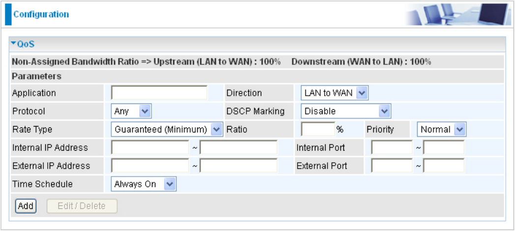
QoS helps you to control the data upload trafc of each application from LAN (Ethernet and/
or Wireless) to WAN (Internet). It facilitates you the features to control the quality and speed of
throughput for each application when the system is running with full upstream load.
After clicking the QoS item, you can Add/Edit/Delete a QoS policy. This page will show the brief
information for policies you have added or edited. This page will also display the total available
(Non-assigned) bandwidth, in percentage, can be assigned.
Application: Assign a name that identies the new QoS application rule.
Direction: The trafc ow direction to be controlled by the QoS policy. There are two settings to be
provided in the Router:
LAN to WAN: Control the trafc ow from the local network to the outside world. For example,
when you have a FTP server inside the local network and want to have a limited trafc rate
controlled by the QoS policy, you need to add a policy with LAN to WAN direction setting.
WAN to LAN: Control Trafc ow from the WAN to LAN. (The connection maybe either issued
from LAN to WAN or WAN to LAN.)
Protocol: Select the supported protocol from the drop down list. For GRE protocol, there is no
need to specify the IP addresses or Application ports in this page. For other protocols, at least one
value shall be given.
Any: No protocol type is specied.
TCP
UDP
ICMP
GRE: For PPTP VPN Connections.
98
99
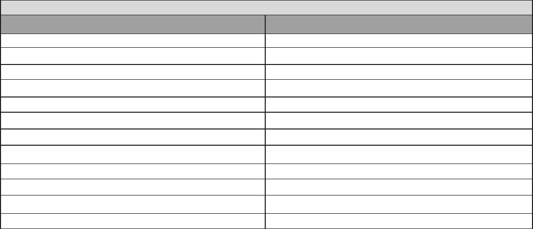
DSCP Marking: Differentiated Services Code Point (DSCP), it is the rst 6 bits in the ToS byte.
DSCP Marking allows users to classify the trafc of the application to be executed according to
the DSCP value. See DSCP Mapping Table.
Note: Make sure that the router(s) in the network backbone are capable to execute and check
the DSCP throughout the QoS network.
DSCP Mapping Table
DSCP Mapping Table
(Wireless) VDSL Router Standard DSCP
Disabled None
Best Effort Best Effort (000000)
Premium Express Forwarding (101110)
Gold service (L) Class 1, Gold (001010)
Gold service (M) Class 1, Silver (001100)
Gold service (H) Class 1, Bronze (001110)
Silver service (L) Class 2, Gold (010010)
Silver service (M) Class 2, Silver (010100)
Silver service (H) Class 2, Bronze (010110)
Bronze service (L) Class 3, Gold (011010)
Bronze service (M) Class 3, Silver (011100)
Bronze service (H) Class 3, Bronze (011110)
Rate Type: Two types are provided:
Limited (Maximum): Specify a limited data rate for this policy. It is the maximal rate for this
policy. As above FTP server example shows, if you want to “throttle” the outgoing FTP speed
to 20% of 100M and limit to it, please choose this type.
Guaranteed (Minimum): Specify a minimal data rate for this policy. For example, if you want to
provide a guaranteed data rate for your outside customers to access your internal FTP server
with, say at least, 20% of your total bandwidthm, please choose this type. Then, if the available
bandwidth is not used, it will be given to this policy by following priority assignment.
Ratio: Assign the data ratio for this policy to be controlled. For examples, when we want to allow
only 20% of the total data transfer rate for the LAN-to-WAN direction to be used for FTP server, we
can specify here with data ratio = 20. If you have VDSL LINE with 100M/bps.rate, the estimated
data rate, in kbps, for this rule is 20%*100*0.9 = 20Mbps. (For 0.9 is an estimated factor for the
effective data transfer rate for a VDSL LINE from LAN to WAN. For WAN-to-LAN, it is 0.85 to 0.8).
Priority: The priority given to each policy/application. You may adjust this setting to t your policy
/ application. For examples, you are allowed to specify two different QoS policies for different
applications. Both applications need minimal or higher bandwidth, besides the assigned one, if
there is any available/non-used one available, you can specify which application can have higher
priority by acquiring the non-used bandwidth.
High
Normal: The default is set to normal.
Low
For the sample priority assignment for different policies, it is served in a First-In-First-Out way.
Internal IP Address: The IP address values for Local LAN machines you want to control. (For IP
packets from LAN to WAN, it is the source IP address. For IP packages from WAN to LAN, it is the
destination IP address.)
Internal Port: The Application port values for local LAN machines you want to control. (For TCP/
UDP packets from LAN to WAN, it is the source port value. For TCP/UDP packets from WAN to
LAN, it is the destination port value.)
External IP Address: The IP address values for Remote WAN machines you want to control. (For
IP packets from LAN to WAN, it is the destination IP address. For IP packages from WAN to LAN,
it is the source IP address.)
External Ports: The Application port values for remote machines you want to control. (For TCP/
UDP packets from LAN to WAN, it is the destination port value. For TCP/UDP packets from WAN
to LAN, it is the source port value.)
Time Schedule: Scheduling your prioritization policy.
Remember clicking Add to save your settings.
100
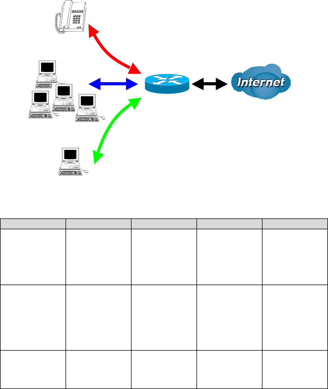
Example: QoS for your Network
Connection Diagram
Application IP / Ports Control Flow Data Rate Time Schedule
VoIP user 192.168.0.1 Outgoing Minimal 20%
with high priority
for non-used
bandwidth with
DSCP marking
Class 1 Gold
Service.
Always
FTP Server 192.168.0.100 Incoming &
Outgoing
Outgoing :minimal
30% data rate.
Incoming :minimal
30% data rate.
Both with low
priority for non-
used bandwidth.
Only during
working hours
9:00 to 17:00
Monday to Friday
HTTP Web user 80 Incoming &
Outgoing
Outgoing : limited
20% data rate.
Incoming : limited
30% data rate.
Always
101
Restricted PC
Normal PCs
VoIP
102
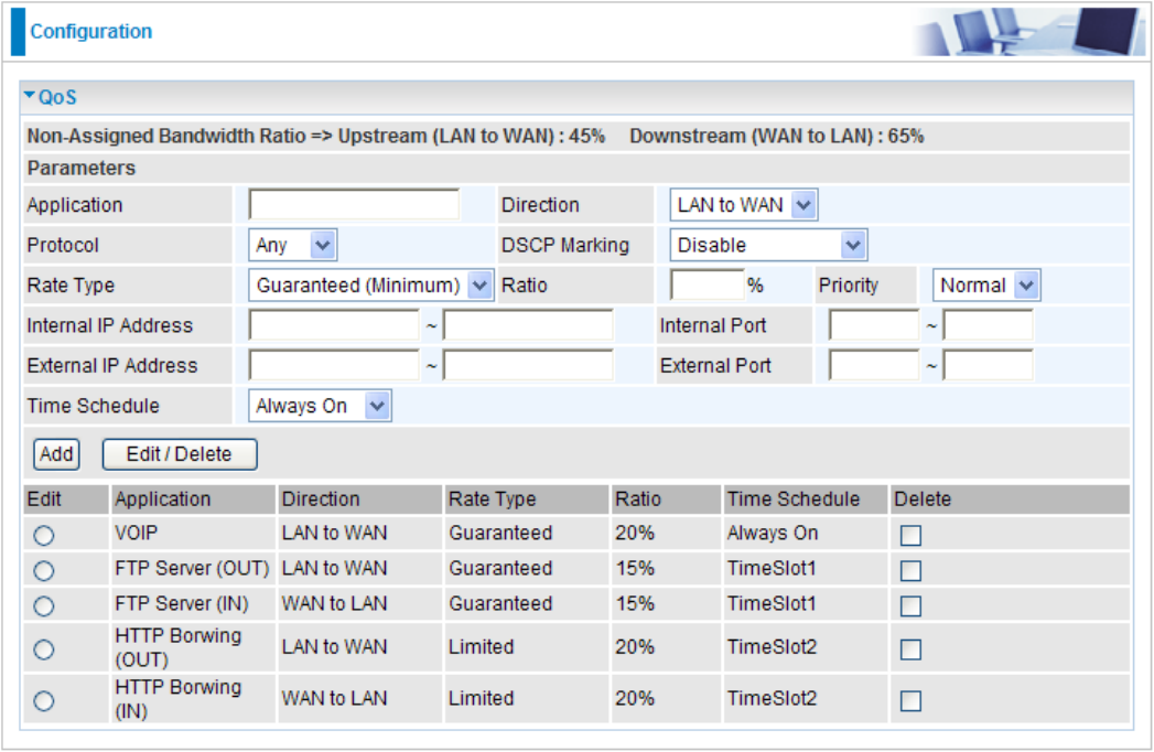
Example: QoS Setup
VoIP application
Voice is latency-sensitive application. Most VoIP devices are used SIP protocol and the port
number will be assigned by SIP module automatically. Better to use xed IP address for catching
VoIP packets as high priority.
103
Virtual Server
Virtual Server allows you to direct incoming trafc from WAN side (identied by Protocol and
External port) to the Internal server with private IP address on the LAN side. The Internal port is
required only if the external port needs to be converted to a different port number used by the
server on the LAN side.
The device can be congured as a virtual server so that remote users accessing services such
as Web or FTP services via the public (WAN) IP address can be automatically redirected to local
servers in the LAN network. Depending on the requested service (TCP/UDP port number), the
device redirects the external service request to the appropriate server within the LAN network.
In TCP and UDP networks a port is a 16-bit number used to identify which application program
(usually a server) incoming connections should be delivered to. Some ports have numbers that
are pre-assigned to them by the IANA (the Internet Assigned Numbers Authority), and these are
referred to as “well-known ports”. Servers follow the well-known port assignments so clients can
locate them.
If you wish to run a server on your network that can be accessed from the WAN (i.e. from other
machines on the Internet that are outside your local network), or any application that can accept
incoming connections (e.g. Peer-to-peer/P2P software such as instant messaging applications and
P2P le-sharing applications) and are using NAT (Network Address Translation), then you need to
congure your router to forward these incoming connection attempts using specic ports to the PC
on your network running the application. You also need to use port forwarding if you wish to host
an online game server.

Example: List of some well-known and registered port numbers.
The Internet Assigned Numbers Authority (IANA) is the central coordinator for the assignment
of unique parameter values for Internet protocols. Port numbers range from 0 to 65535, but only
ports numbers 0 to 1023 are reserved for privileged services and are designated as “well-known
ports” (Please refer to Table below). The registered ports are numbered from 1024 through
49151. The remaining ports, referred to as dynamic or private ports, are numbered from 49152
through 65535.
Examples of well-known and registered port numbers are shown below, for further information,
please see IANA’s website at: http://www.iana.org/assignments/port-numbers.
For help on determining which private port numbers are used by common applications on this list,
please see the FAQs (Frequently Asked Questions) at http://www.billion.com.
Well-known and Registered Ports
Port Number Protocol Description
20 TCP FTP Data
21 TCP FTP Control
22 TCP & UDP SSH Remote Login Protocol
23 TCP Telnet
25 TCP SMTP (simple Mail Transfer Protocol)
53 TCP & UDP DNS (Domain Name Server)
69 UDP TFTP (Trivial File Transfer Protocol)
80 TCP World Wide Web HTTP
110 TCP POP3 (Post Ofce Protocol version 3)
119 TCP NEWS (Network News Transfer Protocol)
123 UDP NTP (Network Time Protocol)
161 TCP SNMP
443 TCP & UDP HTTPS
1503 TCP T.120
1720 TCP H.323
4000 TCP ICQ
7070 UDP Real Audio
104
105
Port Mapping
Since NAT acts as a “natural” Internet rewall, your router protects your network from accessed
by outside users, as all incoming connection attempts point to your router unless you specically
create Virtual Server entries to forward those ports to a PC on your network. When your router
needs to allow outside users to access internal servers, e.g. a web server, FTP server, Email
server or game server, the router can act as a “virtual server”. You can set up a local server with
a specic port number for the service to use, e.g. web/HTTP (port 80), FTP (port 21), Telnet (port
23), SMTP (port 25), or POP3 (port 110). When an incoming access request the router for a
specied port is received, it is forwarded to the corresponding internal server.
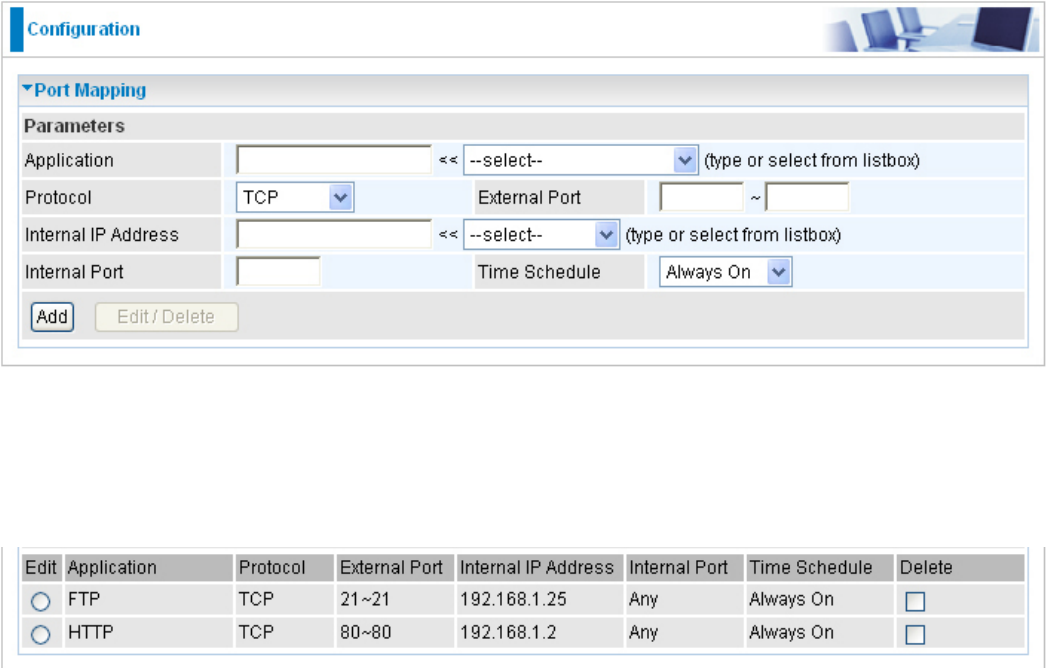
For example, if you set the port number 80 (Web/HTTP) to be mapped to the IP Address
192.168.1.2, then all incoming HTTP requests from outside users are forwarded to the local server
(PC) with the IP address of 192.168.1.2. If the port is not listed as a predened application, you
need to add it manually.
In addition to specifying the port number used, you also need to specify the protocol used. The
protocol is determined by a particular application. Most applications use TCP or UDP, however you
may also specify other protocols using the drop-down Protocol menu. Setting the protocol to “all”
causes all incoming connection attempts using all protocols on all port numbers to be forwarded to
the specied IP address.
Application: Select the service you wish to congure.
Protocol: A protocol is automatically applied when an Application is selected from the listbox or
you may select a protocol type which you want. The protocol used to be determined by a particular
application. Most applications will use TCP or UDP.
External Port & Internal Port: Enter the public port number & range you wish to congure.
Internal IP Address: Enter the IP address of a specic internal server to which requests from the
specied port is forwarded.
Time Schedule: Scheduling your prioritization policy.
Add: Click to add a new virtual server rule. Click again and the next gure appears.
Edit: Check the Edit radio button to display the parameter of the selected application, then after
changing the parameters click the Edit/Delete button to apply the changes.
Delete: To remove a port mapping application, check the Delete box of the selected application
then click the Edit/Delete button.
106
107
DMZ
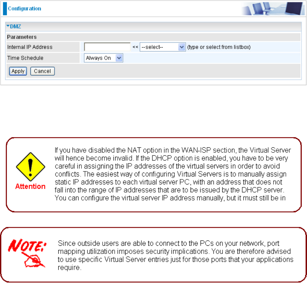
The DMZ Host is a local computer exposed to the Internet. When setting a particular internal IP
address as the DMZ Host, all incoming packets that do not use a port number which is already
used by any other Virtual Server entries will rst be checked by the Firewall and NAT algorithms
before it is passed to the DMZ host.
Cautious: This Local computer exposing to the Internet may face various security risks.
Time Schedule: Scheduling your prioritization policy.
Click Apply to conrm the settings.

108
Wake on LAN
WOL allows the router to set a command to turn on a particular computer that can support this
feature.
Click Add to save the setting.
Edit: Check the Edit radio button to display the parameter of the selected entry, then after
changing the parameters click the "Edit/Delete" button to apply the changes.
Delete: To remove a static route entry, check the Delete box of the selected entry then click the
"Edit/Delete" button.
Time Schedule
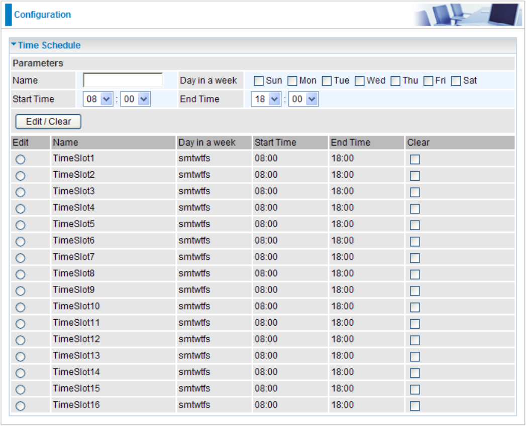
The Time Schedule supports up to 16 time slots which helps you to manage your Internet
connection. In each time prole, you may schedule specic day(s) i.e. Monday through Sunday to
restrict or allowing the usage of the Internet by users or applications.
This Time Schedule correlates closely with router’s time, since router does not have a real time
clock on board; it uses the Simple Network Time Protocol (SNTP) to get the current time from an
SNTP server from the Internet. Refer to Time Zone for details. You router time should correspond
with your local time. If the time is not set correctly, your Time Schedule will not function properly.
Name: A user-dene description to identify this time portfolio.
Day in a week: The default is set from Sunday through Saturday. You may specify the days for the
schedule to be applied.
Start Time: The default is set at 8:00 AM. You may specify the start time of the schedule.
End Time: The default is set at 18:00 (6:00PM). You may specify the end time of the schedule.
Click the Edit/Clear button to save your changes.
109

110
Advanced
Conguration options within the Advanced section are for users who wish to take advantage of
the more advanced features of the router. Users who do not understand the features should not
attempt to recongure their router, unless advised to do so by support staff.
Here are the items within the Advanced section: Static Route, Static ARP, Dynamic DNS, VLAN,
Device Management, IGMP, SNMP Access Control and Remote Access.
Static Route
With static route feature, you are equipped with the capability to control the routing of the all
the trafc across your network. With each routing rule created, you can specically assign the
destination where the trafc will be routed to.
Destination: Enter the destination IP where the trafc is to be forwarded.
Netmask: Enter the netmask of the destination.
Gateway: Enter the gateway address for the trafc.
Interface: Select an appropriate interface for the new routing rule from the drop down menu.
Cost: This is the same meaning as Hop and represents the cost of transmission for routing
purposes. The number need not be precise, but it must between 0 and 65535; usually be left at 1.
Click Add to conrm the settings.
Edit: Check the Edit radio button to display the parameter of the selected rule, then after changing
the parameters click the "Edit/Delete" button to apply the changes.
Delete: To remove a static route entry, check the Delete box of the selected rule then click the
"Edit/Delete" button.

Static ARP
This feature allows you to map the layer-2 MAC (Media Access Control) address that corresponds
to the layer-3 IP address of the device.
IP Address: Enter the IP of the device that the corresponding MAC address will be mapped to.
MAC Address: Enter the MAC address that corresponds to the IP address of the device.
Click Add to conrm the settings.
Edit: Check the Edit radio button to display the parameter of the selected application, then after
changing the parameters click the "Edit/Delete" button to apply the changes.
Delete: To remove a static ARP entry, check the Delete box of the selected entry then click the
"Edit/Delete" button.
111
Dynamic DNS
The Dynamic DNS function lets you alias a dynamic IP address to a static hostname, so if your
ISP does not assign you a static IP address you can still use a domain name. This is especially
useful when hosting servers via your WAN connection, so that anyone wishing to connect to you
may use your domain name, rather than the dynamic IP address which is assigned to you by ISP.
You need to rst register and establish an account with the Dynamic DNS provider using their
website, for example http://www.dyndns.org/.
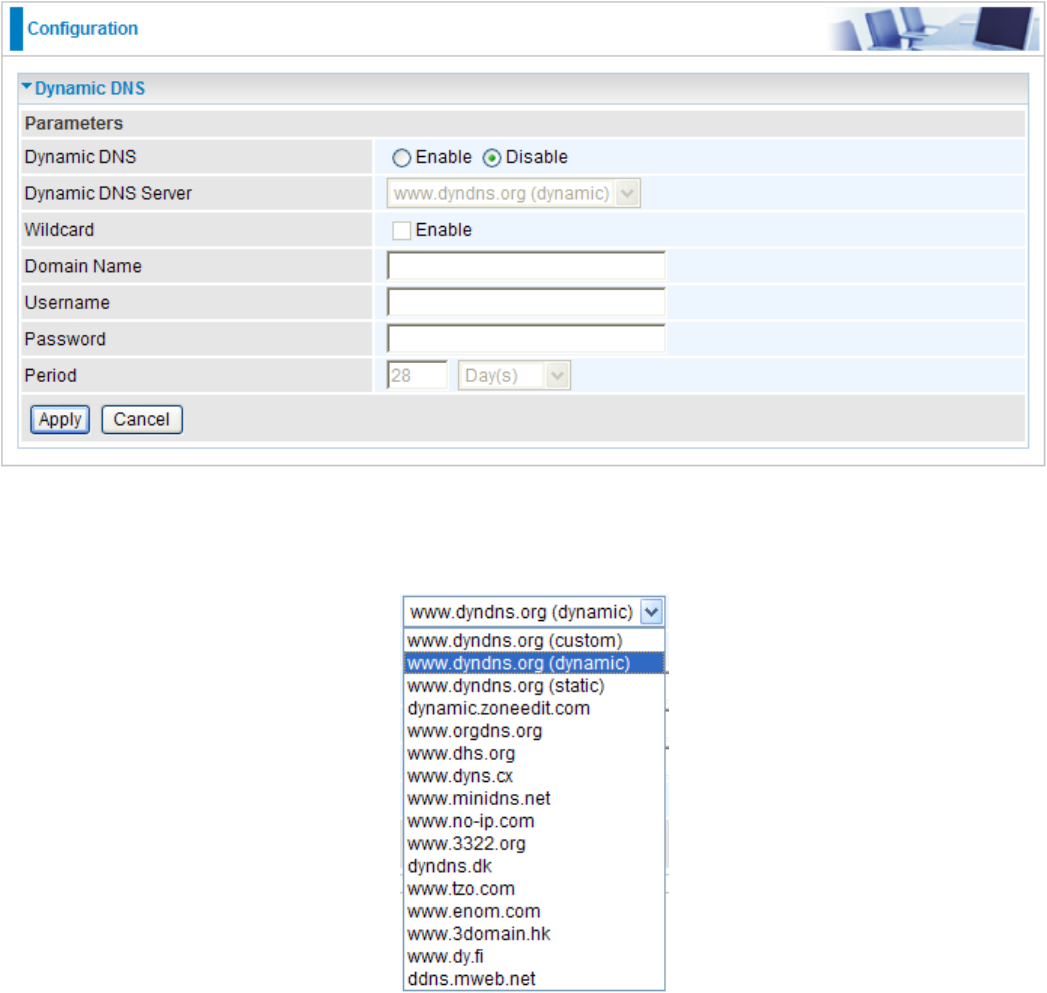
Dynamic DNS: Default is disabled. Check Enable to enable the Dynamic DNS function and the
following elds will be activated and required.
Dynamic DNS Server: Select the DDNS service you have registered an account with.
Wildcard: When enabled, you allow the system to lookup on domain names that do not exist to
have MX records synthesized for them.
Domain Name, Username and Password: Enter your registered domain name and your
username and password for this service.
Period: Enter the length of the period in the blank, you can set the period unit in day, hour or
minute.
Click Apply to conrm the settings.
112
113
VLAN
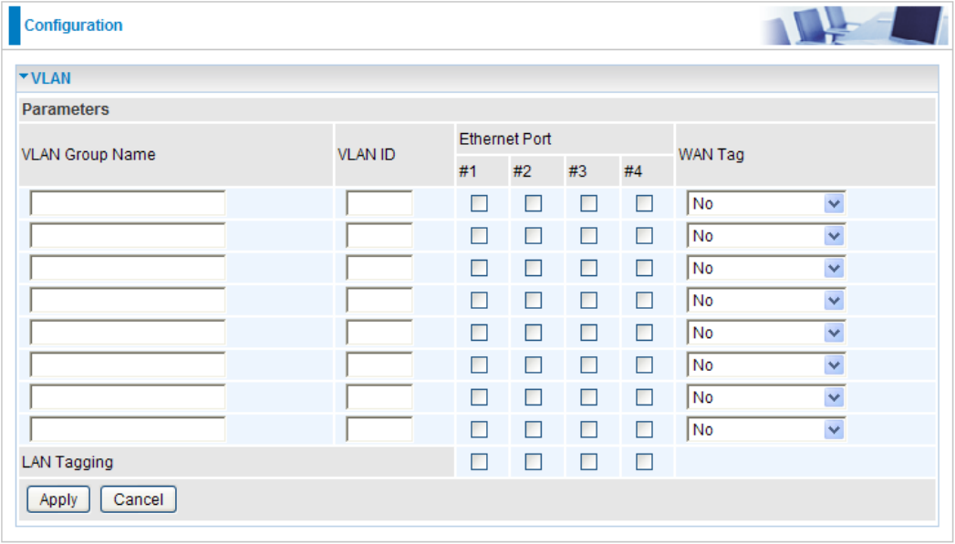
VLAN (Virtual Local Area Network) is a group of devices on different physical LAN segments that
can communicate with each other as if they were all on the same physical LAN segment.
VLAN Group Name: Please input VLAN name of this rule.
VLAN ID: Please input VLAN ID that will be used for Tagged member port(s).
Ethernet Port(s): Please check the interface that you would like to use in this VLAN ID group.
WAN Tag: Select the WAN Tag from the drop-down menu to associate the VLAN Group with it.
Click Apply to conrm the settings.
114
Device Management
The Device Management advanced conguration settings allows you to control your router’s
security options and device monitoring features.
Device Host Name
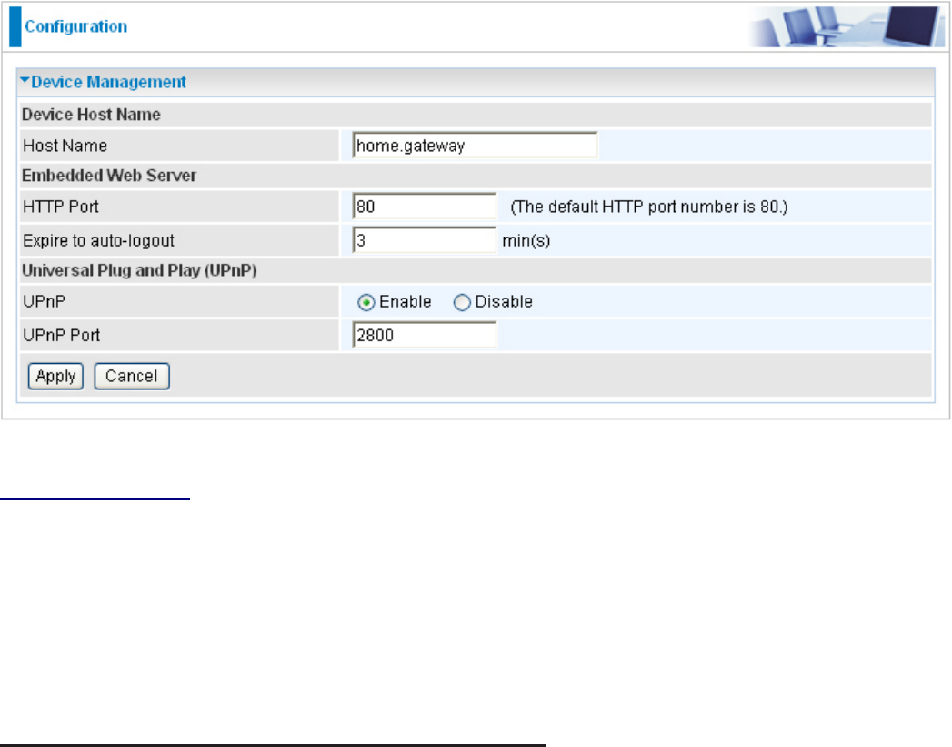
Host Name: Assign it a name.
(The Host Name cannot be used with one word only. There are two words should be
connected with a ‘.’ at least.
Example:
Host Name: homegateway ==> Incorrect
Host Name: home.gateway or my.home.gateway ==> Correct)
Embedded Web Server ( 2 Management IP Accounts)
HTTP Port: This is the port number the router’s embedded web server (for web-based
conguration) will use. The default value is the standard HTTP port, 80. Users may specify an
alternative if, for example, they are running a web server on a PC within their LAN.
Expire to auto-logout: Specify a time length for the system to auto-logout user from the
conguration session.
Example: User A enters 100 for HTTP port number, species 192.168.1.55 for his/hser own IP
address, and sets the logout time to 100 minutes. The router will allow User A to access only
from the IP address 192.168.1.55 to logon to the Web GUI by typing: http://192.168.1.254:100
in their web browser. After 100 minutes, User A is logged out by the device automatically.

Universal Plug and Play (UPnP)
UPnP offers peer-to-peer network connectivity for PCs and other network devices, along with the
feature to control data transfer between devices. UPnP offers many advantages for users running
NAT routers through UPnP NAT Traversal, and on supported systems. By letting the application
control the required settings and removing the need for the user to control the advanced
conguration of their device will make tasks such as port forwarding become easier.
Both user’s Operating System and its relevant applications must support UPnP in addition to the
router. Windows XP and Windows Me have a native built-in support for UPnP (when the component
is installed). Windows 98 users may have to install the Internet Connection Sharing client from
Windows XP in order to support UpnP feature. Windows 2000 does not support UPnP.
Disable: Check to inactive the router’s UPnP functionality.
Enable: Check to active the router’s UPnP functionality.
UPnP Port: Default setting is 2800. It is highly recommended for users to use this port value.
If this value conicts with other ports that have been used, you are allowed to change the port
number.
Click Apply to conrm the settings.
115
116
Installing UPnP in Windows Example
Follow the steps below to install the UPnP in Windows Me.
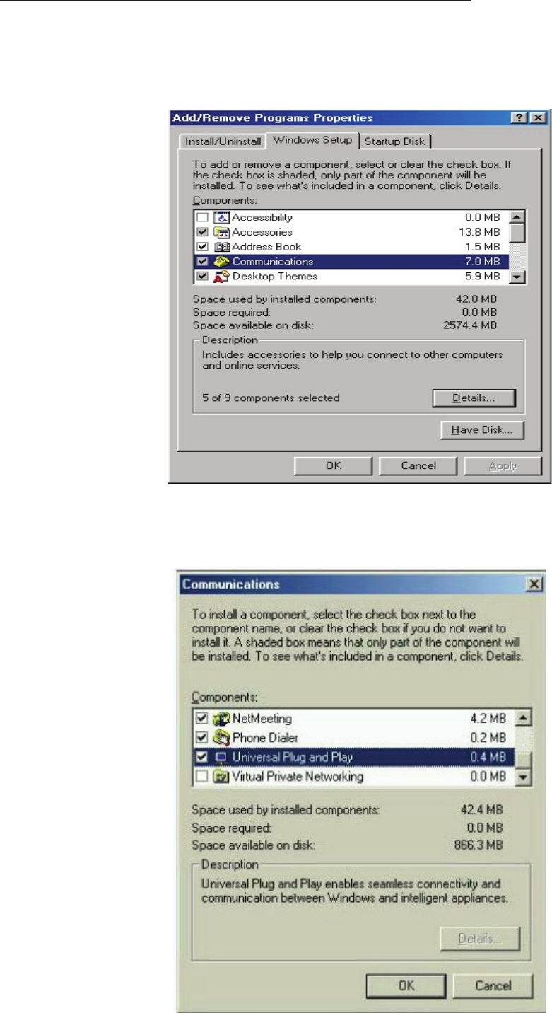
Step 1: Click Start and Control Panel. Double-click Add/Remove Programs.
Step 2: Click on the Windows Setup tab and select Communication in the Components selection
box. Click Details.
Step 3: In the Communications window, select the Universal Plug and Play check box in the
Components selection box.
117
Step 4: Click OK to go back to the Add/Remove Programs Properties window. Click Next.
Step 5: Restart the computer when prompted.
Follow the steps below to install the UPnP in Windows XP.
Step 1: Click Start and Control Panel.
Step 2: Double-click Network Connections.
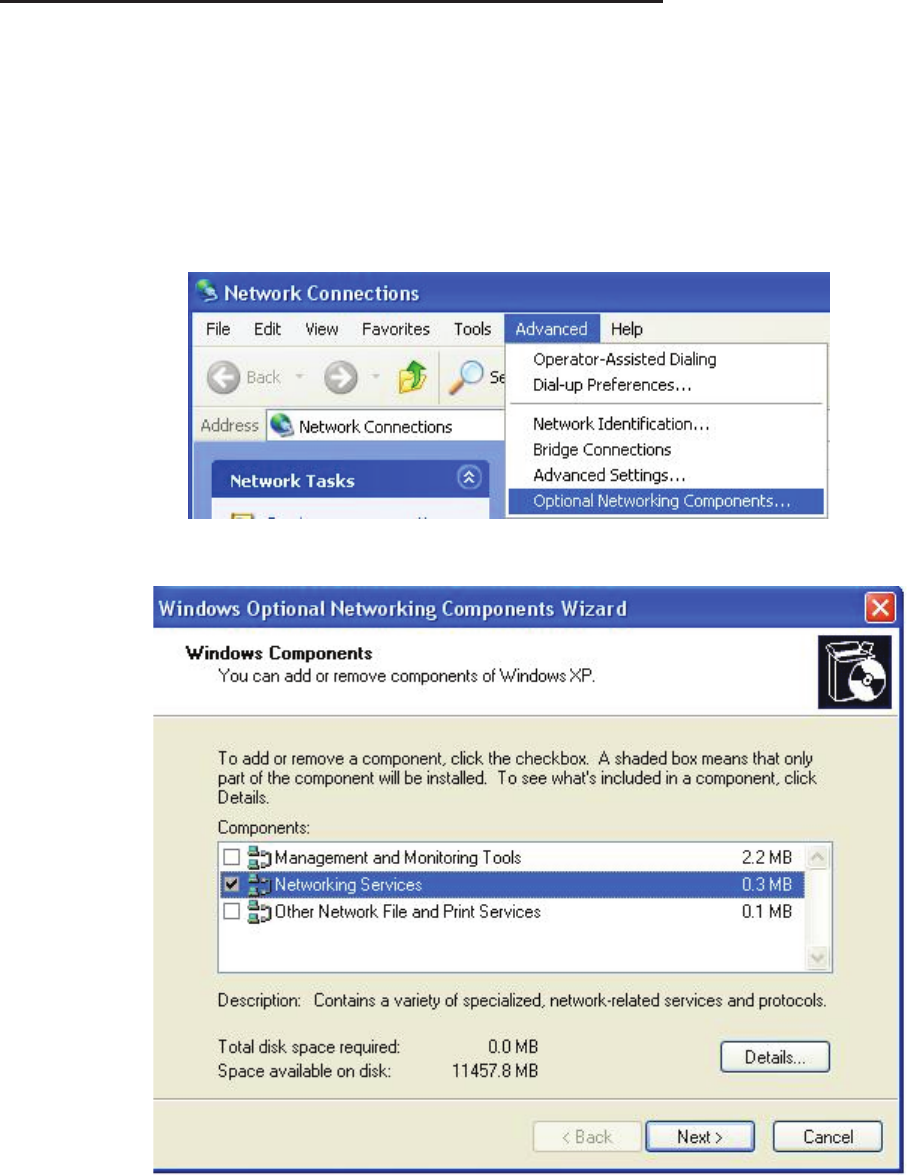
Step 3: In the Network Connections window, click Advanced in the main menu and select Optional
Networking Components ….
Step 4: When the Windows Optional Networking Components Wizard window appears, select
Networking Service in the Components selection box and click Details.
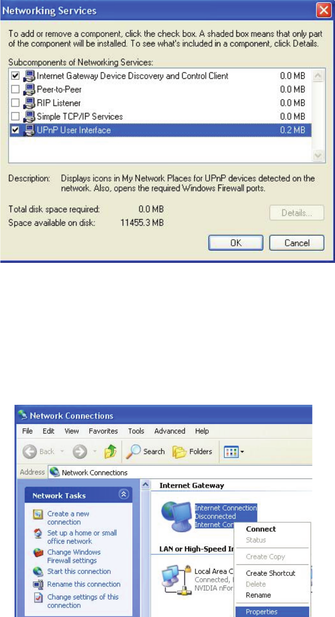
Step 5: In the Networking Services window, select the Universal Plug and Play check box.
118
Step 6: Click OK to go back to the Windows Optional Networking Component Wizard window and
click Next.
Auto-discover Your UPnP-enabled Network Device
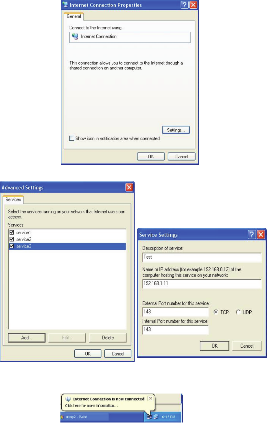
Step 1: Click start and Control Panel. Double-click Network Connections. An icon displays under
Internet Gateway.
Step 2: Right-click the icon and select Properties.
Step 3: In the Internet Connection Properties window, click Settings to see the port mappings that
were automatically created.
119
Step 4: You may edit or delete the port mappings or click Add to manually add port mappings.
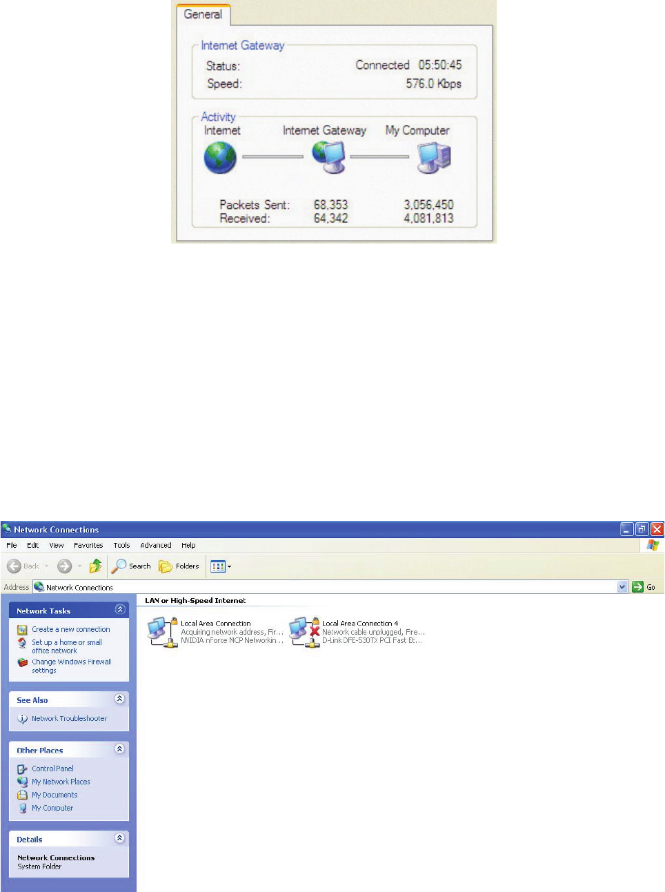
Step 5: Select Show icon in notication area when connected option and click OK. An icon
displays in the system tray.
120
Step 6: Double-click on the icon to display your current Internet connection status.
Web Congurator Easy Access
With UPnP, you can access web-based conguration for the BiPAC 8200N without rst nding out
the IP address of the router. This helps if you do not know the router’s IP address.
Follow the steps below to access web conguration.
Step 1: Click Start and then Control Panel.
Step 2: Double-click Network Connections.
Step 3: Select My Network Places under Other Places.
Step 4: An icon describing each UPnP-enabled device shows under Local Network.
Step 5: Right-click on the icon of your BiPAC 8200N and select Invoke. The web conguration
login screen displays.
Step 6: Right-click on the icon of your BiPAC 8200N and select Properties. A properties window
displays basic information about the BiPAC 8200N.

121
IGMP
IGMP, known as Internet Group Management Protocol, is used to manage hosts from multicast
group.
IGMP Proxy: IGMP proxy enables the system to issue IGMP host messages on behalf of the
hosts that the system has discovered through standard IGMP interfaces. The system acts as a
proxy for its hosts.
IGMP Snooping: Allows a layer 2 switch to manage the transmission of any incoming IGMP
multicast packet groups between the host and the router. Default is set to Disable.
Click Apply to conrm the changes.
Example:
When IGMP snooping is enabled, the feature will analyze all incoming IGMP packets
between the hosts that are connected to the switch and the multicast routers in the
network. When the layer 2 switch receives an IGMP report from a host requesting for a
given multicast group, the switch will add the host’s port number to the multicast list for
that multicast group to be forwarded to. And, when the layer 2 switch has detected that an
IGMP has left, it will remove the host’s port from the table entry.
SNMP Access Control
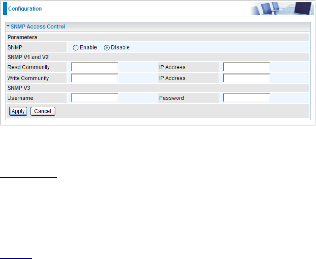
Software on a PC within the LAN is required in order to utilize this function – Simple Network
Management Protocol.
Parameters
SNMP: Select Enable / Disable to activate / inactivate this function.
SNMP V1 and V2
Read Community: Specify a name to be identied as the Read Community, and an IP address.
This community string will be checked against the string entered in the conguration le. Once the
string name is matched, user obtains this IP address will be able to view the data.
Write Community: Specify a name to be identied as the Write Community, and an IP address.
This community string will be checked against the string entered in the conguration le. Once the
string name is matched, users from this IP address will be able to view and modify the data.
SNMP V3
Specify a name and password for authentication. And dene the access right from identied IP
address. Once the authentication has succeeded, users from this IP address will be able to view
and modify the data.
Click Apply to conrm the settings.
122
123
Remote Access
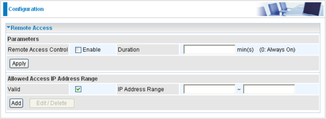
Remote Access Control:
Enable: Select Enable to allow management access from remote side (mostly from
internet).
Duration: Set how many minutes to allow management access from remote side. Zero(0)
means always on.
Click Apply to conrm the settings.
Allowed Access IP Address Range:
Valid: Select Valid to allow remote management from these IP ranges.
IP Address Range: Specify the remote IP address which will be allowed access device.
Clink Add to insert management IP address(es) to the list.
Click Add to conrm the settings.

Save Conguration to Flash
After changing the router’s conguration settings, you must save all of the conguration
parameters to FLASH to avoid losing them after turning off or resetting your router. Click “Save
Cong“ and click “Apply” to write your new conguration to FLASH.
124

Restart
Click “Restart” with option Current Settings to reboot your router (and restore your last saved
conguration).
If you wish to restart the router using the factory default settings (for example, after a rmware
upgrade or if you have saved an incorrect conguration), select Factory Default Settings to reset to
factory default settings
125
Logout
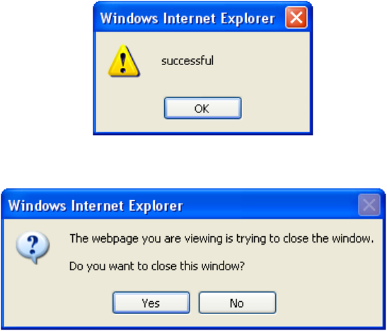
To exit the router web interface, click “Logout”. Please save your conguration setting before
logging out of the system. A Warning screen will appear as below.
Click OK and a message displays. Click Yes to close the window.
Be aware that the router conguration interface can only be accessed by one PC at a time.
Therefore when a PC has logged into the system interface, the other users cannot access the
system interface until the current user has logged out of the system. If the previous user forgets to
logout, the second PC can only access the router web interface after a user-dened auto logout
period which is by default 3 minutes. You can however modify the value of the auto logout period
using the Advanced > Device Management section of the router web interface. Please see the
Advanced section of this manual for more information.
126

Chapter 5: Troubleshooting
If your router is not functioning properly, please refer to the suggested solutions provided in this
chapter. If your problems persist or the suggested solutions do not meet your needs, please kindly
contact your service provider or Billion for support.
Problems with the router
Problem Suggested Action
None of the LEDs lit when the router is
turned on
Check the connection between the router and the
adapter. If the problem persists, most likely it is due
to the malfunction of your hardware. Please contact
your service provider or Billion for technical support.
You have forgotten your login username
or password
Try the default username & password (Please refer
to Chapter 3). If this fails, restore your router to its
default setting by pressing the reset button for more
than 6 seconds.
Problem with LAN interface
Problem Suggested Action
Cannot PING any PC on LAN Check the Ethernet LEDs on the front panel.
The LED should be on for the port that has a PC
connected. If it does not lit, check to see if the
cable between your router and the PC is properly
connected. Make sure you have rst uninstalled
your rewall program before troubleshooting.
127

128
Appendix: Product Support & Contact
If you come across any problems please contact the dealer from where you purchased your prod-
uct.
Contact Billion
MAC OS is a registered Trademark of Apple Computer, Inc.
Windows 98, Windows NT, Windows 2000, Windows Me, Windows XP and Windows Vista are
registered Trademarks of Microsoft Corporation.
Worldwide:
http://www.billion.com

Regulatory Approvals
FCC Statement
This equipment has been tested and found to comply with the limits for a Class B digital
device, pursuant to Part 15 of the FCC Rules. These limits are designed to provide reasonable
protection against harmful interference in a residential installation.
This equipment generates, uses and can radiate radio frequency energy and, if not installed and
used in accordance with the instructions, may cause harmful interference to radio communica-
tions. However, there is no guarantee that interference will not occur in a particular installation.
If this equipment does cause harmful interference to radio or television reception, which can be
determined by turning the equipment off and on, the user is encouraged to try to correct the
interference by one of the following measures:
Reorient or relocate the receiving antenna.
Increase the separation between the equipment and receiver.
Connect the equipment into an outlet on a circuit different from that to which the receiver
is connected.
Consult the dealer or an experienced radio/TV technician for help.
To assure continued compliance, any changes or modifications not expressly approved by the
party responsible for compliance could void the user's authority to operate this equipment.
(Example - use only shielded interface cables when connecting to computer or peripheral
devices).
FCC Radiation Exposure Statement
This equipment complies with FCC RF radiation exposure limits set forth for an uncontrolled
environment. This equipment should be installed and operated with a minimum distance of 20
centimeters between the radiator and your body.
This device complies with Part 15 of the FCC Rules. Operation is subject to the following two
conditions:
(1) This device may not cause harmful interference, and
(2) This device must accept any interference received, including interference that may cause
undesired operation.
This transmitter must not be co-located or operating in conjunction with any other antenna or
transmitter.
The antennas used for this transmitter must be installed to provide a separation distance of at
least 20 cm from all persons and must not be co-located or operating in conjunction with any
other antenna or transmitter.
Channel
The Wireless Channel sets the radio frequency used for communication.
•Access Points use a fixed Channel. You can select the Channel used. This allows you to
choose a Channel which provides the least interference and best performance. In the USA
and Canada, 11 channel are available. If using multiple Access Points, it is better if adjacent
Access Points use different Channels to reduce interference.
• In "Infrastructure" mode, Wireless Stations normally scan all Channels, looking for an
Access Point. If more than one Access Point can be used, the one with the strongest
signal is used. (This can only happen within an ESS.)
• If using "Ad-hoc" mode (no Access Point), all Wireless stations should be set to use the
same Channel. However, most Wireless stations will still scan all Channels to see if there
is an existing "Ad-hoc" group they can join.
Note:This equipment marketed in USA is restricted by firmware to only operate on 2.4G channel 1-11
.