Billion Electric BIL-8200NX (3G) 802.11n VDSL (VPN) Firewall Router User Manual Users manual
Billion Electric Co., Ltd. (3G) 802.11n VDSL (VPN) Firewall Router Users manual
Contents
- 1. Users manual
- 2. Users manual-02
- 3. Users manual-03
Users manual

BiPAC 8200N
802.11n VDSL2 4-port Firewall Router
User Manual
Last revised on July 2009
Table of Contents
Chapter 1: Product ............................................................................1
Introduction to your Router ..........................................................1
Features .....................................................................................4
Hardware Specications ............................................................5
Physical Specications........................................................................5
Power Requirements...........................................................................5
Operating Environment ...............................................................5
Chapter 2: Product Overview............................................................6
Package Contents .......................................................................7
Important note for using this router .............................................7
Device Description ...................................................................... 8
The Front LEDs ...................................................................................8
The Rear Ports ...................................................................................9
Cabling ...................................................................................... 11
Chapter 3: Basic Installation .........................................................12
Applications of the device .........................................................13
Network Conguration ...............................................................14
Conguring PC in Windows Vista......................................................14
Conguring PC in Windows XP .........................................................16
Conguring PC in Windows 2000 .....................................................17
Conguring PC in Windows 95/98/Me...............................................18
Conguring PC in Windows NT4.0 ....................................................19
Factory Default Settings ............................................................20
Information from your ISP ....................................................... 21
Chapter 4: Conguration ................................................................22
Easy Sign-On (EZSO) ...............................................................22
Conguration via Web Interface ................................................25
Quick Start ................................................................................26
Basic Conguration Mode .........................................................33
Status ................................................................................................33
WAN – Main Port: VDSL ...................................................................34
Obtain IP Address Automatically (VDSL) ........................................................ 34
Fixed IP Address (VDSL) ................................................................................ 35
PPPoE Connection (VDSL) ............................................................................ 36
Pure Bridge (VDSL) ........................................................................................ 37
WAN – Main Port: EWAN ..................................................................38
Obtain IP Address Automatically (EWAN) ....................................................... 38
Fixed IP Address (EWAN) .............................................................................. 39
PPPoE Connection (EWAN) ........................................................................... 40
WLAN ................................................................................................41
Advanced Conguration Mode ..................................................43
Status ................................................................................................43
VDSL Status ................................................................................................... 45
ARP Table ....................................................................................................... 46
DHCP Table .................................................................................................... 47
System Log..................................................................................................... 48
Firewall Log .................................................................................................... 49
UPnP Portmap ................................................................................................ 50
Conguration .....................................................................................51
LAN - Local Area Network .............................................................................. 52
WAN - Wide Area Network ............................................................................. 72
System ........................................................................................................... 81
Firewall ........................................................................................................... 88
QoS - Quality of Service ................................................................................. 98
Virtual Server ................................................................................................ 103
Time Schedule .............................................................................................. 109
Advanced...................................................................................................... 110
Save Conguration to Flash .................................................... 124
Restart ....................................................................................125
Logout ..................................................................................... 126
Chapter 5: Troubleshooting .......................................................... 127
Appendix: Product Support & Contact ........................................128
Chapter 1: Product
Introduction to your Router
Thank you for purchasing BiPAC 8200N Router. Your new router is an all-in-one unit that combines
a VDSL modem, VDSL2 router and Ethernet network switch to provide everything you need to get
the machines on your network connected to the Internet over a VDSL broadband connection.
The BiPAC 8200N is an all-in-one VDSL2 Router with the latest draft 802.11n technology. It is
designed for home and SOHO users who seek extreme mobility, high-speed wireless connection
and better wireless coverage while maintaining high-speed broadband access with VDSL2.
The BiPAC 8200N is capable of offering optimal speeds and coverage over the integrated wireless
802.11n access point. The device supports the highest rate of up to 100Mbps/100Mbps in VDSL2
Prole (30a). Since VDSL2 has the characteristic of faster rates over shorter distances, the ideal
architecture for Telcoms is to use ber optic lines as the backbone and a VDSL2 line as the last
mile into the home or ofce. VDSL2 operates over copper wires so that telecom operators can
provide bundled services to end-users similar to those that cable operators offer.
With outstanding throughput, the BiPAC 8200N can complement a ber network to offer the best
solution for delivering IPTV or home entertainment services. The SOHO Firewall is integrated to
provide protection against hacker attacks while the Quality of Service prioritizes queues and trafc
for applications such as music downloads, online gaming, video streaming and le sharing.
Express Internet Access – VDSL2 capable
The router complies with VDSL worldwide standards. Supporting downstream rates of 100Mbps
with VDSL and upstream rates of 100 Mbps. Users enjoy not only high-speed VDSL services but
also broadband multimedia applications such as interactive gaming, video streaming and real-
time audio which are easier and faster than ever. The router is compliant with ITU G994.1 and ITU
G.997.1. Support VDSL2 Proles: 8a, 8b, 8c, 8d, 12a, 12b, 17a and 30a.
802.11n Wireless AP with WPA Support
With integrated 802.11n Wireless Access Point in the router, the device offers a quick and easy
access among wired network, wireless network and broadband connection (VDSL) with single
device simplicity, and as a result, mobility to the users. In addition to 300 Mbps 802.11n data
rate, it also interoperates backward with existing 802.11g and 802.11b equipment. The Wireless
Protected Access (WPA) and Wireless Encryption Protocol (WEP) supported features enhance the
security level of data protection and access control via Wireless LAN.
Fast Ethernet Switch
A 4-port 10/100Mbps fast Ethernet switch is built-in with automatic switching between MDI and
MDI-X for 10Base-T and 100Base-TX ports, with auto detection allowing you to use either straight
or cross-over Ethernet cables.
1
EWAN
Besides using VDSL to get connected to the Internet, this router offers its Ethernet port 4 as a
WAN port to be used to connect to Cable Modems and ber optic lines. This alternative, yet faster
method to connect to the internet will provide users more exibility to get online.
Multi-Protocol to Establish a Connection
The router supports PPP over Ethernet, DHCP Client and Fixed IP address to establish a
connection with an ISP.
Universal Plug and Play (UPnP) and UPnP NAT Traversal
This protocol is used to enable simple and robust connectivity among stand-alone devices and
PCs from many different vendors. It makes network simple and affordable for users. UPnP
architecture leverages TCP/IP and the Web to enable seamless proximity networking in addition to
control and data transfer among networked devices. With this feature enabled, you can seamlessly
connect to Net Meeting or MSN Messenger.
Network Address Translation (NAT)
It allows multi-users to access outside resources such as the Internet simultaneously with one IP
address/one Internet access account. Many application layer gateway (ALG) are supported such
as web browser, ICQ, FTP, Telnet, E-mail, News, Net2phone, Ping, NetMeeting, IP phone and
others.
Firewall
NAT technology supports simple rewalls and provides options for blocking access from the
Internet, like Telnet, FTP, TFTP, WEB, SNMP and IGMP.
Domain Name System (DNS) Relay
It provides an easy way to map the domain name (a friendly name for users such as www.yahoo.
com) and IP address. When a local machine sets its DNS server with this router’s IP address,
every DNS conversion request packet from the PC to this router will be forwarded to the real DNS
in the outside network.
Dynamic Domain Name System (DDNS)
The Dynamic DNS service allows you to alias a dynamic IP address to a static hostname. This
dynamic IP address is the WAN IP address. For example, to use the service, you must rst apply
for an account from a DDNS service like http://www.dyndns.org/. More than 5 DDNS servers are
supported.
PPP over Ethernet (PPPoE)
This device provides an embedded PPPoE client function to establish a connection. You get
greater access speed without changing the operation concept, while sharing the same ISP
account and paying for one access account. No PPPoE client software is required for the local
computer. Automatic Reconnect and Disconnect Timeout (Idle Timer) functions are also provided.
2
Quality of Service (QoS)
QoS gives you full control over which types of outgoing data trafc should be given priority by
the router, ensuring important data like gaming packets, customer information, or management
information move through the router ay lightning speed, even under heavy load. The QoS features
are congurable by Internal IP address, External IP address, protocol, and port. You can throttle
the speed at which different types of outgoing data pass through the router, to ensure P2P users
don’t saturate upload bandwidth, or ofce browsing doesn’t bring client web serving to a halt. In
addition, or alternatively, you can simply change the priority of different types of upload data and
let the router sort out the actual speeds.
Virtual Server
Users can specify some services to be visible from outside users. The router can detect incoming
service requests and forward either a single port or a range of ports to the specic local computer
to handle it. For example, a user can assign a PC in the LAN acting as a WEB server inside and
expose it to the outside network. Outside users can browse inside web servers directly while it is
protected by NAT. A DMZ host setting is also provided to a local computer exposed to the outside
network, Internet.
Dynamic Host Conguration Protocol (DHCP) Client and Server
In a WAN site, the DHCP client obtains an IP address from the Internet Service Provider (ISP)
automatically. In a LAN site, the DHCP server allocates a range of client IP addresses, including
subnet masks and DNS IP addresses and distributes them to local computers. This provides an
easy way to manage the local IP network.
Rich Packet Filtering
Not only lters the packet based on IP address, but also based on Port numbers. It will lter
packets from and to the Internet, and also provides a higher level of security control.
Web-based GUI
It supports web based GUI for conguration and management. It is user-friendly and comes with
on-line help. It also supports remote management capability for remote users to congure and
manage this product.
Firmware Upgradeable
Device can be upgraded to the latest rmware through the WEB based GUI.
3
Features
• Compliant with ITU-T G.994.1 and 997.1 VDSL2 Standard
• VDSL2 Proles: 8a/b/c/d, 12a/b, 17a, 30a
• Band Plan 997 and 998 supported
• Annex A, Annex B, Annex C supported
• US0 Supported
• OLR Supported
• Compliant with VDSL2 MIB
• Integrated 4-port Ethernet Switch
• Ideal for LRE applications
• SOHO Firewall Security with DoS Prevention and Packet Filtering
• Universal Plug and Play (UPnP) Compliant
• Easy Sign-On (EZSO) and Web-based Conguration
• Quality of Service Control
• Easy Network Management
• Supports Draft-802.11n Wireless Access Point with WPA-PSK / WPA2-PSK
• WPS (Wi-Fi Protected Setup) for Easy Setup
• Wireless Speed up to 300Mbps and 3 Times the Coverage of Standard 802.11b/g
• Multiple SSID
4
5
Hardware Specications
Physical Interface
• WLAN: 2 x 2 dBi antennas
• DSL: VDSL port
• Ethernet: 4-port 10/100Mbps auto-crossover (MDI / MDI-X) Switch
• Reset button
• WPS push button
• Power jack
• Power switch
Physical Specications
• Dimensions: 7.09” x 4.72” x 1.57” (180mm x 120mm x 40mm)
Power Requirements
• Input: 12V DC, 1.2A
Operating Environment
• Operating temperature: 00C ~ 400C
• Storage temperature: -200C ~ 700C
• Humidity: 20 - 95% non-condensing
Chapter 2: Product Overview
Standards-Based Technology
The BiPAC 8200N Wireless Router utilizes the 802.11n standard. The IEEE 802.11n standard is
an extension of the 802.11g standard. It increases the data rate up to 300 Mbps within the 2.4GHz
band, utilizing OFDM technology. This means that in most environments, within the specied
range of this device, you will be able to transfer large les quickly or even watch a movie in MPEG
format over your network without noticeable delays. This technology works by transmitting high-
speed digital data over a radio wave utilizing OFDM (Orthogonal Frequency Division Multiplexing)
technology. OFDM works by splitting the radio signal into multiple smaller sub-signals that are then
transmitted simultaneously at different frequencies to the receiver. OFDM reduces the amount of
crosstalk (interference) in signal transmissions.
Installation Considerations
The BiPAC 8200N Wireless Router lets you access your network, using a wireless connection,
from virtually anywhere within its operating range. Keep in mind, however, that the number,
thickness and location of walls, ceilings, or other objects that the wireless signals must pass.
Keep the number of walls and ceilings between the BiPAC 8200N and other network devices to a
minimum - each wall or ceiling can reduce your BiPAC 8200N wireless product’s range from 3-90
feet (1-30 meters.)
Position your devices so that the number of walls or ceilings is minimized. Be aware of the direct
line between network devices. Position the devices so that the signal will travel straight through
a wall or ceiling (instead of at an angle) for better reception. Building Materials can impede the
wireless signal - a solid metal door or aluminium studs may have a negative effect on range.
Try to position wireless devices and computers with wireless adapters so that the signal passes
through drywall or open doorways and not other materials. Keep your product away (at least
3-6 feet or 1-2 meters) from electrical devices or appliances that generate extreme RF (radio
frequency) noise.
6
Package Contents
• BiPAC 8200N VDSL2 Router
• CD containing the online manual
• RJ-11 VDSL/telephone Cable (1.8M)
• Ethernet (CAT-5 LAN) Cable (1.8M Straight)
• AC-DC power adapter (12V DC, 1.2A)
• Quick Start Guide
• Two antennas
• Power adapter
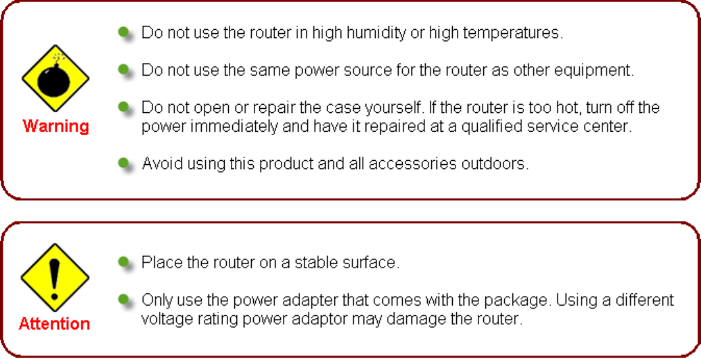
Important note for using this router
7
Device Description
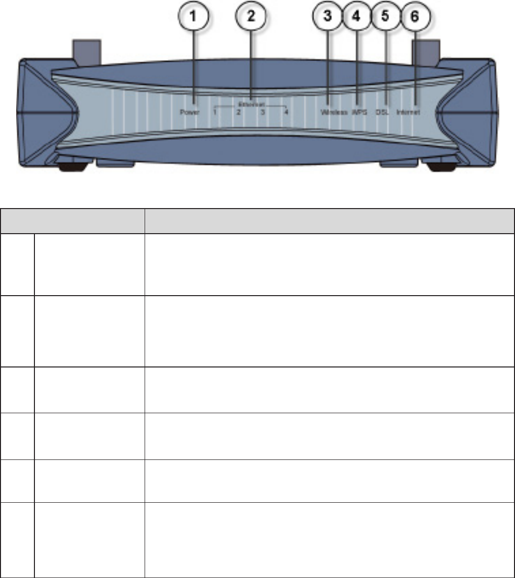
The Front LEDs
LED Meaning
1 Power
Lit red when the device is booting.
Lit green when the system is ready.
Flashes when the system is rebooting or rmware upgrading.
2
Ethernet port
1X — 4X
(RJ-45 connector)
Lit when one of LAN ports is connected to an Ethernet device.
Lit green when the speed of transmission hits 100Mbps; Lit orange
when the speed of transmission hits 10Mbps.
Blinking when data is transmitted/received.
3 Wireless Lit green when a wireless connection is established.
Blinking when data is transmitted/received.
4 WPS Lit green when a wireless connection is established.
Blinking when WPS conguration is in progress.
5 DSL Lit green when the device is successfully connected to an VDSL
DSLAM. (“line sync”)
6Internet
Lit red when WAN port fails to get IP address.
Lit green when WAN port gets IP address successfully.
Lit off when the device is in bridge mode or when WAN connection
absent.
8
9
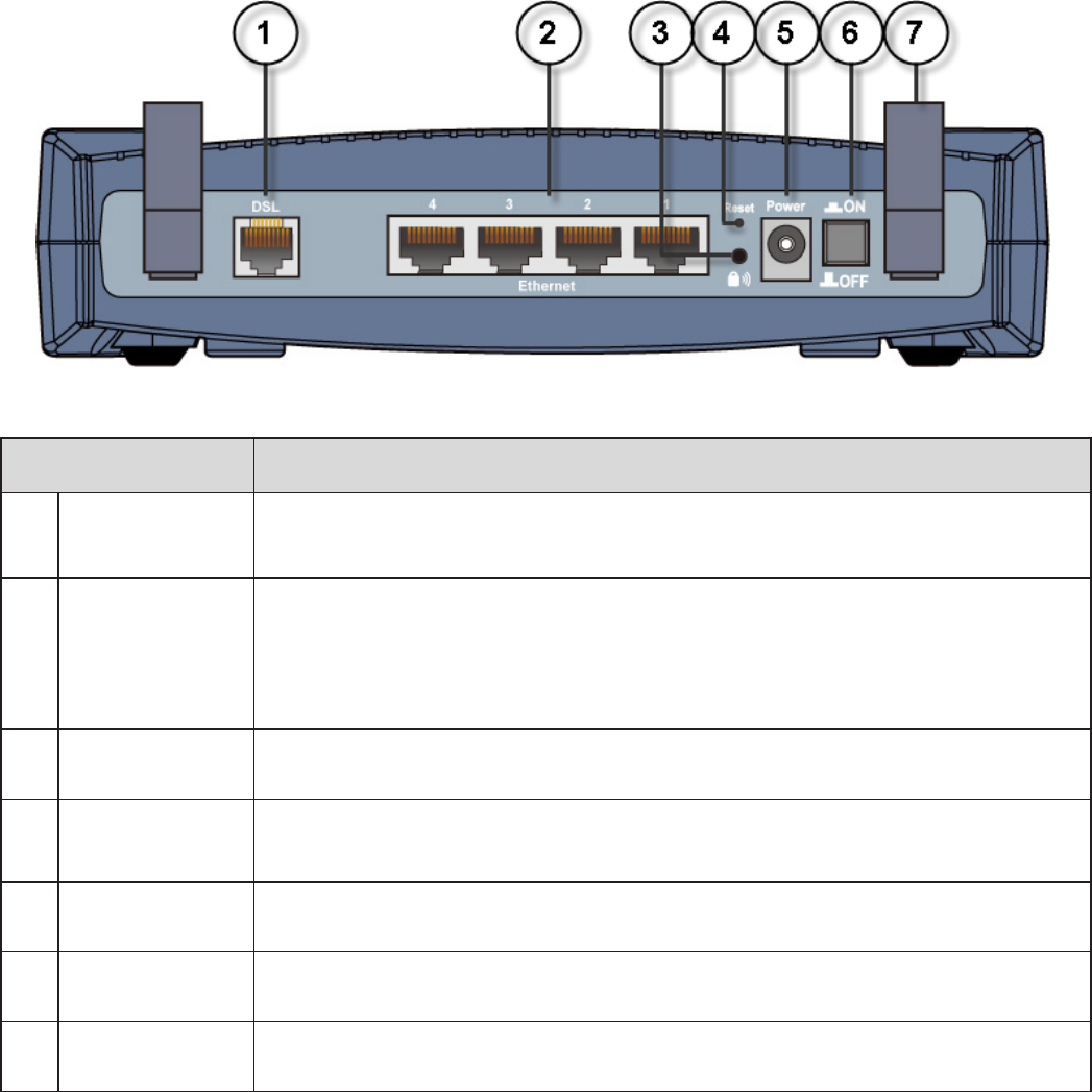
The Rear Ports
Port Meaning
1 DSL Connect this port to the VDSL/telephone network with the RJ-11 cable
(telephone) provided.
2 Ethernet
Connect a UTP Ethernet cable (Cat-5 or Cat-5e) to one of the four LAN
ports when connecting to a PC or an ofce/home network of 10Mbps or
100Mbps.
Note: Only Ethernet port 4 can be used for EWAN.
3 WPS Push this button to trigger Wi-Fi Protected Setup function.
4 Reset Press this button for more than 1 second to restore the device to its
default mode.
5 Power Connect it with the supplied power adapter.
6 Power Switch Power ON/OFF switch.
7 Antenna Connect the detachable antenna to this port.
10
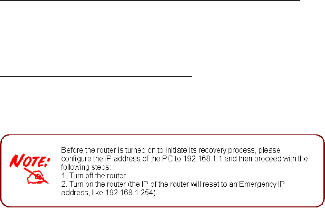
Recovery Operation
1. Recovery procedures for non-working routers (e.g. after a failed rmware upgrade ash):
The system will check the rmware of this device automatically while turning on the modem. Once
the rmware is not integrated, the system enters the recovery state. The modem emergency-
reash web interface will then be accessible via http://192.168.1.254 where you can upload a
rmware image to restore the modem to a functional state. Please note that the modem will only
respond via its web interface at this address, and will not respond to ping requests from your PC
or to telnet connections.
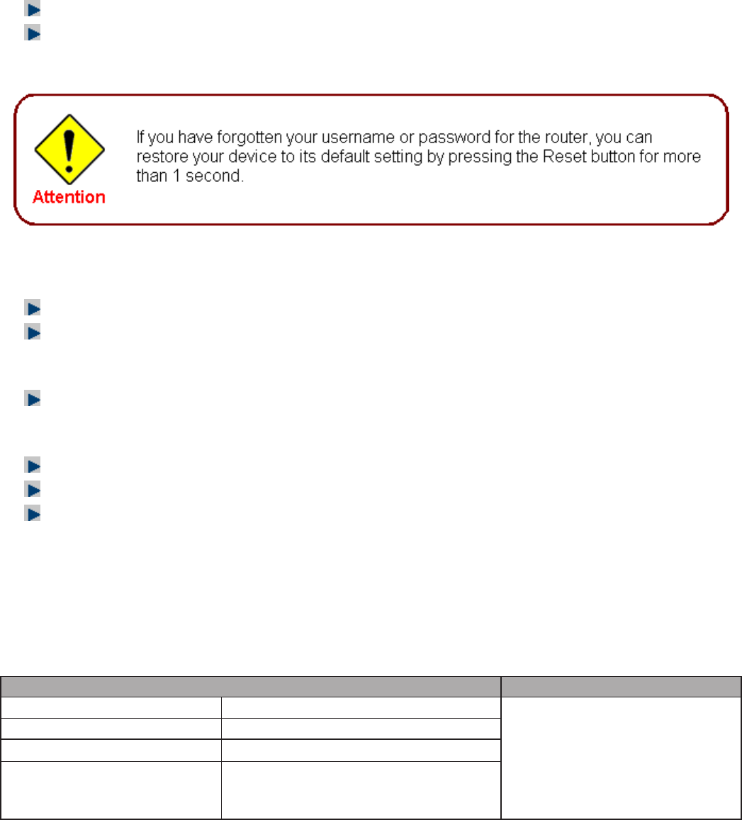
2. Recovery procedures for a lost web interface password:
After turning the router on, please press the Reset Button on the back of the modem, and hold
the button until all the lights on the modem begin to ash and then it will reboot itself to restore the
factory default settings. The login username and password will then be reset to admin. You can
then access its GUI via its default IP address at http://192.168.1.254/.
Cabling
One of the most common causes of problems is because of bad cabling or VDSL line(s). Make
sure that all connected devices are turned on. On the front of the product is a bank of LEDs. Verify
that the LAN Link and VDSL line LEDs are lit. If they are not, verify that you are using the proper
cables.
Ensure that all other devices connected to the same telephone line as your router (e.g.
telephones, fax machines, analog modems) have a line lter connected between them and the
wall socket (unless you are using a Central Splitter or Central Filter installed by a qualied and
licensed electrician), and that all line lters are correctly installed in a right way. If line lter is not
installed and connected properly, it may cause problem to your VDSL connection or may result in
frequent disconnections.
11

Chapter 3: Basic Installation
The router can be congured through your web browser. A web browser is included as a standard
application in the following operating systems: Linux, Mac OS, Windows 98/NT/2000/XP/Me/Vista,
etc. The product provides an easy and user-friendly interface for conguration.
Please check your PC network components. The TCP/IP protocol stack and Ethernet network
adapter must be installed. If not, please refer to your Windows-related or other operating system
manuals.
There are ways to connect the router, either through an external repeater hub or connect directly
to your PCs. However, make sure that your PCs have an Ethernet interface installed properly
prior to connecting the router device. You ought to congure your PCs to obtain an IP address
through a DHCP server or a xed IP address that must be in the same subnet as the router. The
default IP address of the router is 192.168.1.254 and the subnet mask is 255.255.255.0 (i.e. any
attached PC must be in the same subnet, and have an IP address in the range of 192.168.1.1
to 192.168.1.253). The best and easiest way is to congure the PC to get an IP address
automatically from the router using DHCP. If you encounter any problem accessing the router web
interface it is advisable to uninstall your rewall program on your PCs, as they can cause problems
accessing the IP address of the router. Users should make their own decisions on what is best to
protect their network.
Please follow the following steps to congure your PC network environment.
12
13
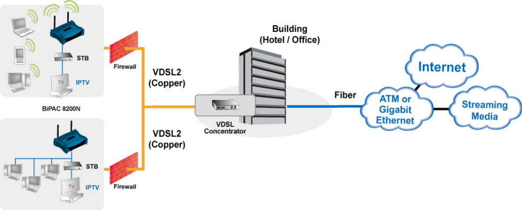
Applications of the device
Deployment scenario for VDSL using FTTx
Network Conguration
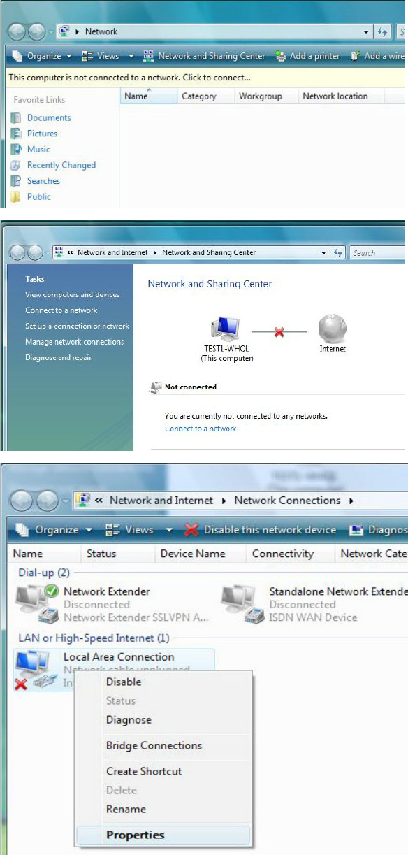
Conguring PC in Windows Vista
1. Go to Start. Click on Network.
2. Then click on Network and Sharing
Center at the top bar.
3. When the Network and Sharing
Center window pops up, select and
click on Manage network connec-
tions on the left window column.
4. Select the Local Area Connection,
and right click the icon to select
Properties.
14
15
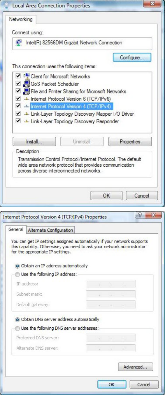
5. Select Internet Protocol Version 4
(TCP/IPv4) then click Properties.
6. In the TCP/IPv4 properties window,
select the Obtain an IP address au-
tomatically and Obtain DNS Server
address automatically radio but-
tons. Then click OK to exit the set-
ting.
7. Click OK again in the Local Area
Connection Properties window to
apply the new conguration.
16
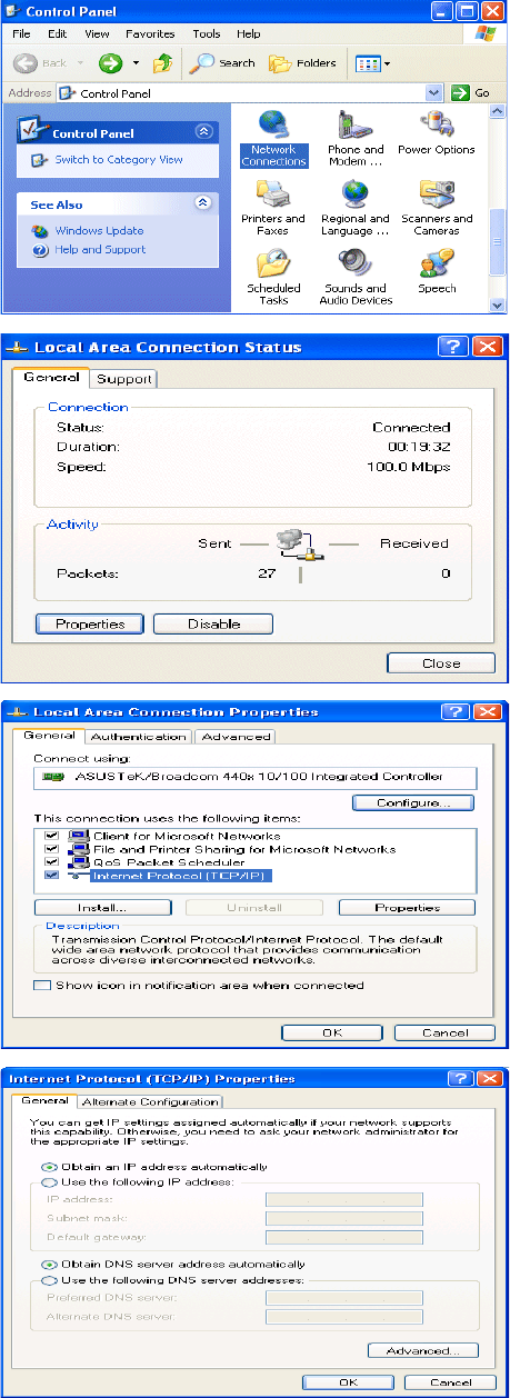
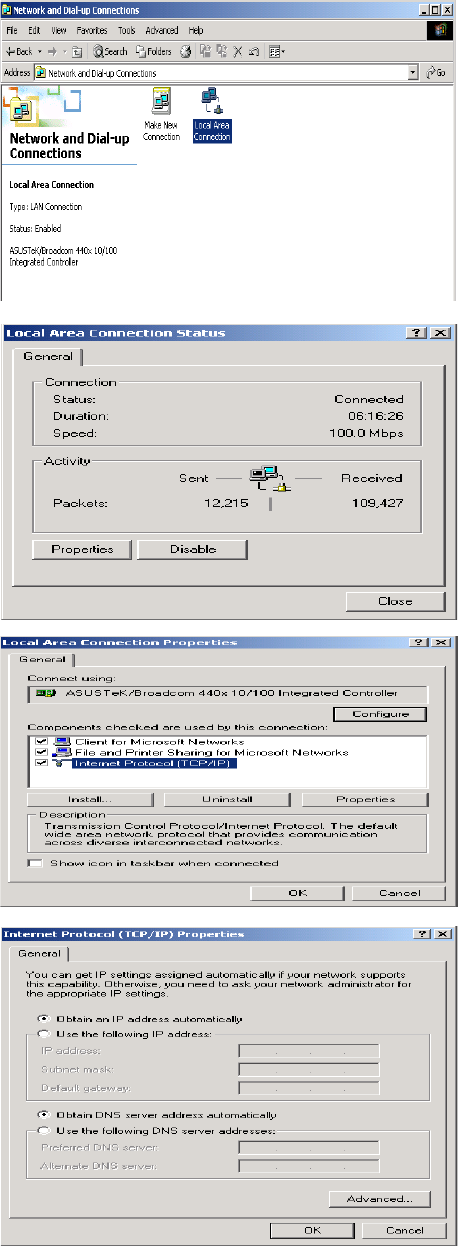
Conguring PC in Windows XP
1. Go to Start > Control Panel (in Classic
View). In the Control Panel, double-click
on Network Connections
2. Double-click Local Area Connection.
3. In the Local Area Connection Status
window, click Properties.
4. Select Internet Protocol (TCP/IP) and
click Properties.
5. Select the Obtain an IP address auto-
matically and the Obtain DNS server
address automatically radio buttons.
6. Click OK to nish the conguration.
17
Conguring PC in Windows 2000
1. Go to Start > Settings > Control Panel.
In the Control Panel, double-click on
Network and Dial-up Connections.
2. Double-click Local Area Connection.
3. In the Local Area Connection Status
window click Properties.
4. Select Internet Protocol (TCP/IP) and
click Properties.
5. Select the Obtain an IP address auto-
matically and the Obtain DNS server
address automatically radio buttons.
6. Click OK to nish the conguration.
18
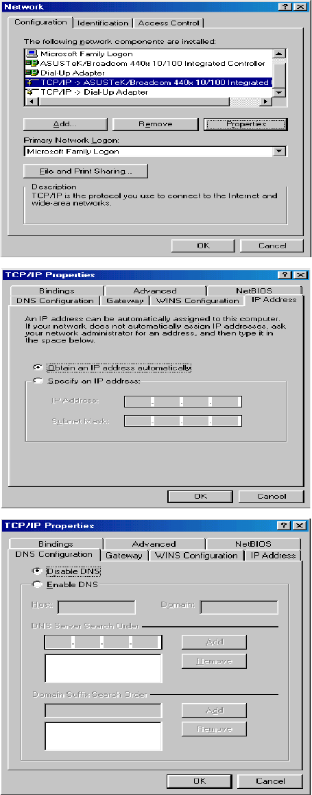
Conguring PC in Windows 95/98/Me
1. Go to Start > Settings > Control Panel.
In the Control Panel, double-click on
Network and choose the Conguration
tab.
2. Select TCP/IP > NE2000 Compatible,
or the name of your Network Interface
Card (NIC) in your PC.
3. Select the Obtain an IP address auto-
matically radio button.
4. Then select the DNS Congurationtab.
5. Select the Disable DNS radio button
and click OK to nish the conguration.
19
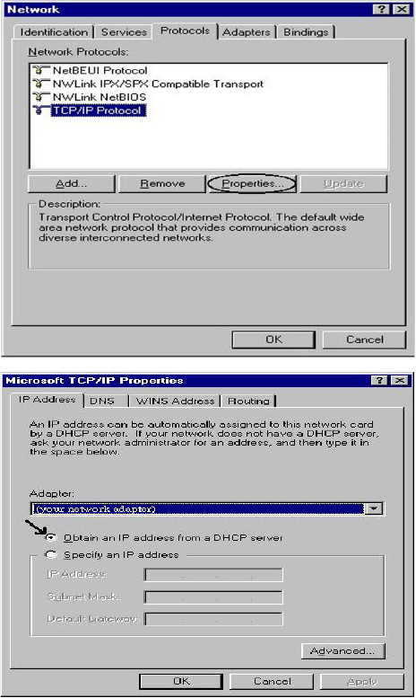
Conguring PC in Windows NT4.0
1. Go to Start > Settings > Control Panel.
In the Control Panel, double-click on
Network and choose the Protocols tab.
2. Select TCP/IP Protocol and click Prop-
erties.
3. Select the Obtain an IP address from
a DHCP server radio button and click
OK.
20
Factory Default Settings
Before conguring your router, you need to know the following default settings.
Web Interface (Username and Password)
Username: admin
Password: admin
The default username and password are “admin” and “admin” respectively.
Device LAN IP settings
IP Address: 192.168.1.254
Subnet Mask: 255.255.255.0
ISP setting in WAN site
PPPoE
DHCP server
DHCP server is enabled.
Start IP Address: 192.168.1.100
IP pool counts: 100
LAN and WAN Port Addresses
The parameters of LAN and WAN ports are pre-set in the factory. The default values are shown in
the tale.
LAN Port WAN Port
IP address 192.168.1.254
The PPPoE function is
enabled to automatically get
the WAN port conguration
from the ISP.
Subnet Mask 255.255.255.0
DHCP server function Enabled
IP addresses for
distribution to PCs
100 IP addresses continuing
from 192.168.1.100 through
192.168.1.199

21
Information from your ISP
Before conguring this device, you have to check with your ISP (Internet Service Provider) to nd
out what kind of service is provided such as PPPoE, Obtain an IP Address Automatically (DHCP),
Fixed IP Address (Static IP).
Gather the information as illustrated in the following table and keep it for reference.
PPPoE
Username, Password, Service Name, and Domain Name System (DNS)
IP address (it can be automatically assigned by your ISP when you
connect or be set manually).
Obtain an IP Address
Automatically
DHCP Client (it can be automatically assigned by your ISP when you
connect or be set manually).
Fixed IP Address IP address, Subnet mask, Gateway address, and Domain Name System
(DNS) IP address (it is xed IP address).
Chapter 4: Conguration
To easily congure this device for internet access, you must have IE 5.0 / Netscape 4.5 or above
installed on your computer. There are basically 2 ways to congure your router before you are able
to connect to the internet: Easy Sign-On & Web Interface. Conguration of each method will be
discussed in detail in the following sections.
Easy Sign-On (EZSO)
This special feature makes it easier for you to congure your router so that you can connect
to the internet in a matter of seconds without having to logon to the router GUI for any detail
conguration. This conguration method is usually auto initiated if user is to connect to the internet
via Billion's router for the rst time.
After setting up the router with all the appropriate cables plugged-in, open up your IE browser,
the EZSO WEB GUI will automatically pop up and request that you enter some basic information
that you have obtained from your ISP. By following the instructions given carefully and through the
information you provide, the router will be congured in no time and you will nd yourself surng
the internet sooner than you realize.
Follow the Easy Sign-On conguration wizard to complete the basic network conguration.
1. Connect your router with all the appropriate cables. Then, load your IE / netscape browser.
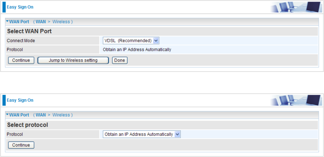
2. When the EZSO conguration wizard pops up, select the connect mode which you want to
set up and then click continue. (There are two mode that you may select: one is “VDSL” and
another is “EWAN”.).
3. Show Auto scan result - Protocol information.
22
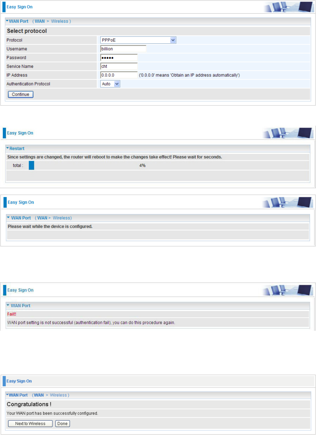
4. Please enter all the information in the blanks provided and then click Continue.
5. The device will reboot and then load the new conguration.
Note: If any error occurs during device conguration that results in WAN connection
failure, the system will prompt that the setup has failed.
6. If all information provided is valid and the device successfully connects to WAN, a dialog box will
appear to signify the completion of the WAN port setup. At this point you can either click Done
to nish the EZSO conguration or you can click Next to wireless to proceed to the wireless
conguration if you have.
23
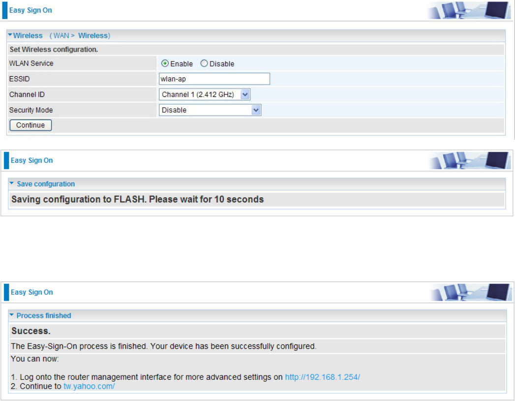
7. Select Enable and enter the necessary information in the blanks provided for the Wireless LAN
setting (wireless setting is only available for BiPAC 8200N) if you would like to use this feature
and then click Continue.
8. The system will save your new conguration and complete the setup. You can test the
connection by clicking on the URL link provided. If the setup is successful you will be redirected
to website.
24
25
Conguration via Web Interface
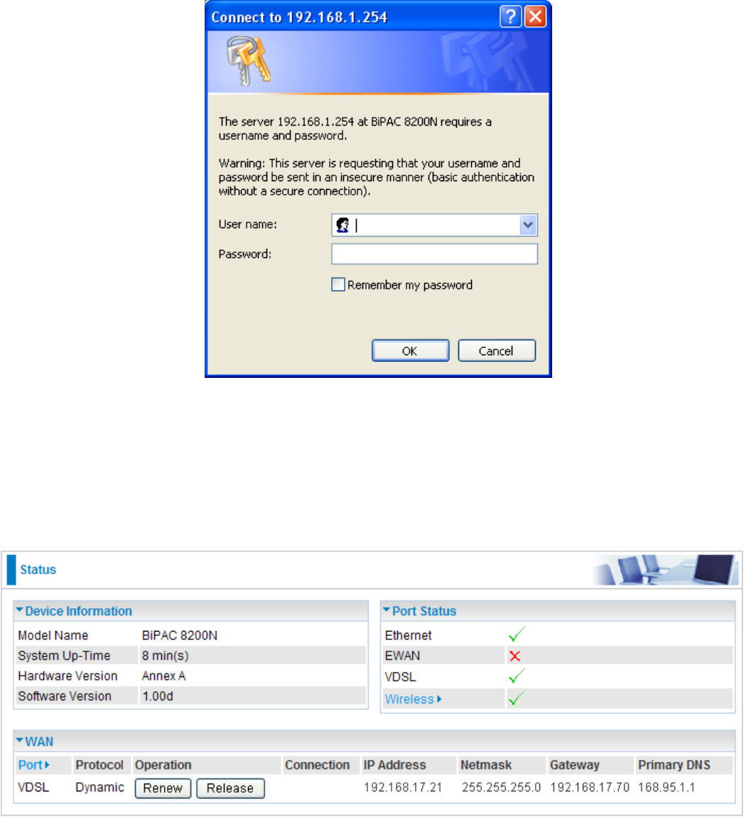
Open your web browser, enter the IP address of your router, which by default is 192.168.1.254, and
click “Go”, a login window prompt will appear. The default username and password are “admin” and
“admin” respectively.
Congratulations! You are now successfully logon to the Router!
If the authentication succeeds, the homepage Status will appear on the screen.
26
Quick Start
Whether on the Basic or Advanced Conguration Mode, click Quick Start link to WAN Port setup
pages.
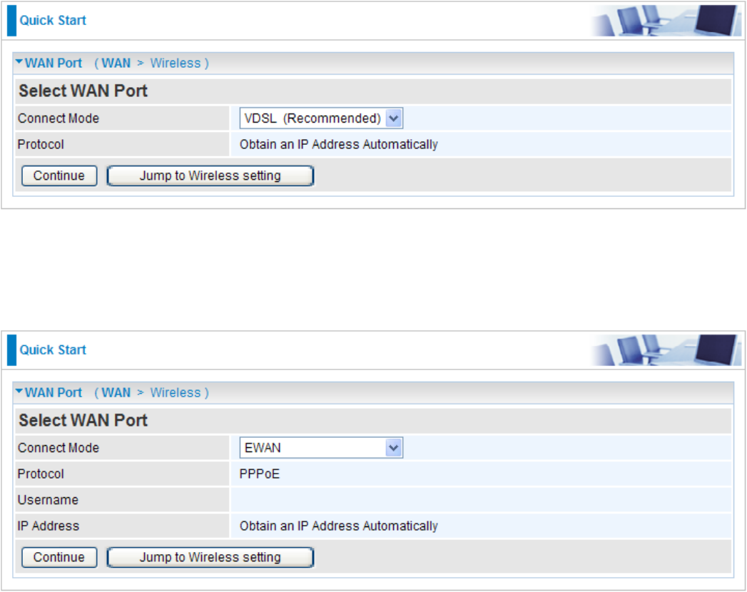
Step 1: This screen displays some information for WAN port. Select Connect Mode from the drop-
down menu. There are 2 modes: VDSL and EWAN. Press Continue to go to the next conguration
page.
VDSL Mode
Connect mode: VDSL
Protocol: Shows the current protocol in the device.
EWAN Mode
Connect mode: EWAN
Protocol: Shows the current protocol in the device.
Username: Shows the current username.
IP address: Shows the current value of IP address in the device.
27
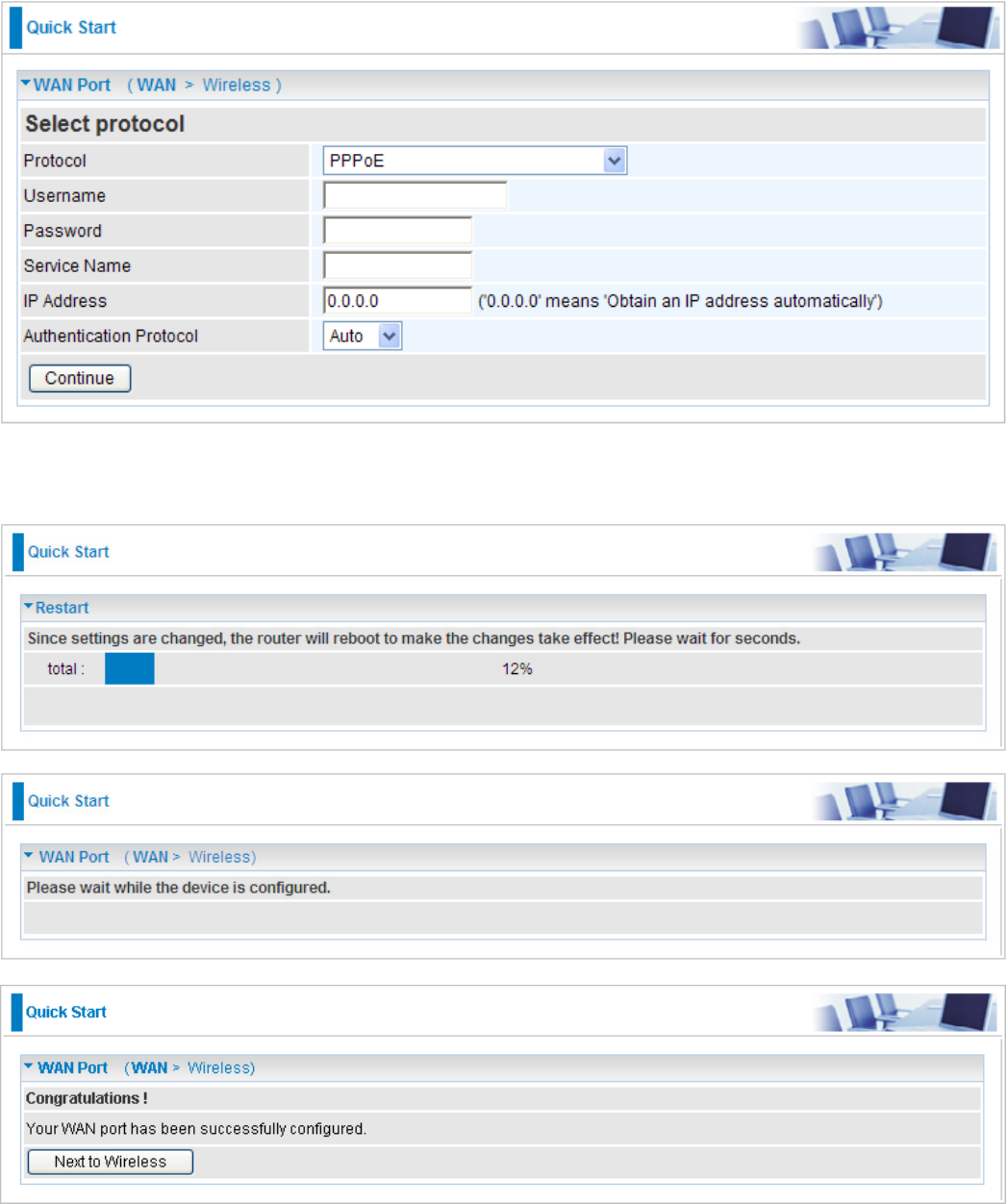
Step 2: Click on Continue to choose the Protocol to connect with EWAN or click Jump to Wireless
Setting to use Protocol. There are 3 types of connection protocols available for WAN connect
mode. Each type of connection mode is described in the following sections of WAN
Connect mode.
Step 3: After nishing conguring the WAN port connection, click Continue to proceed. The system
will upload and apply the new WAN port conguration to the device.
28
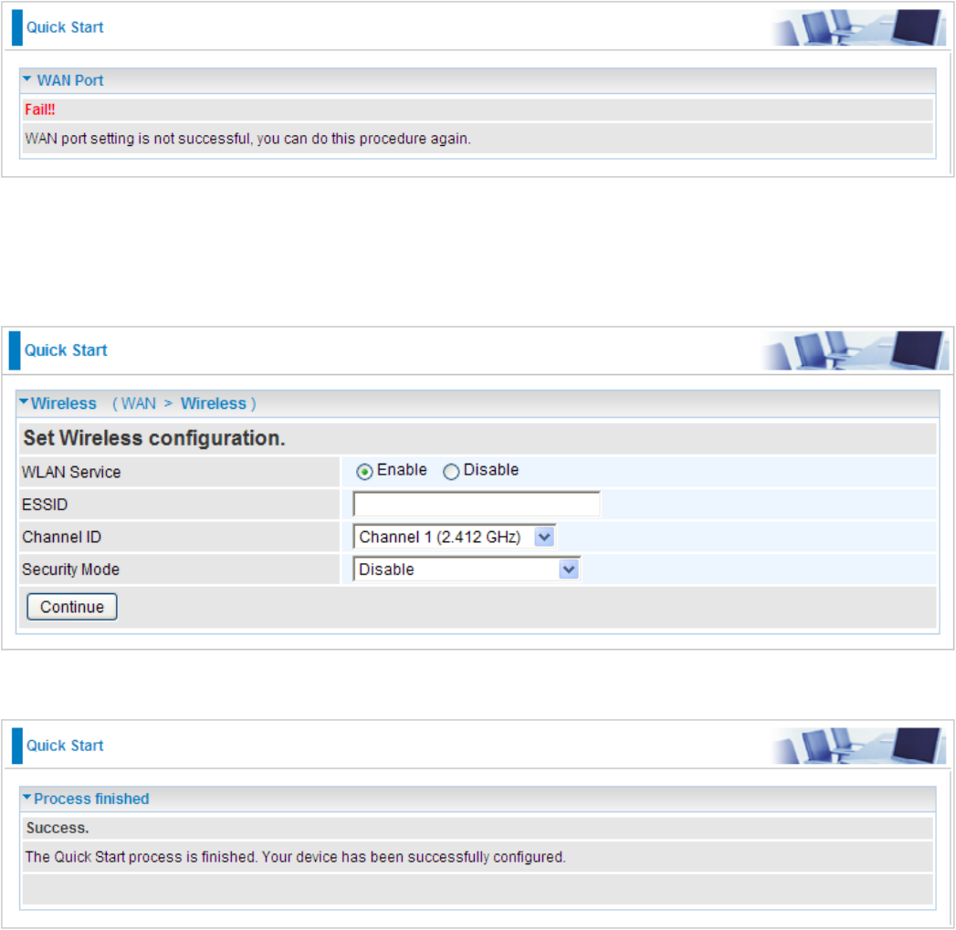
Note: If the WAN line is not ready, a page will display as below and your new conguration
can not be saved.
Step 4: After the conguration is successful, click Next to Weireless button and you may proceed
to congure the Wireless setting. There are 4 types of security mode: WPA, WPA2, WPA/
WPA2 Pre-Shared Key and WEP. Please refer to the Wireless Setting Mode section for detail
description of each security mode.
Step 5: After nishing conguring the WLAN setting, press Continue to nish the QuickStart.
29
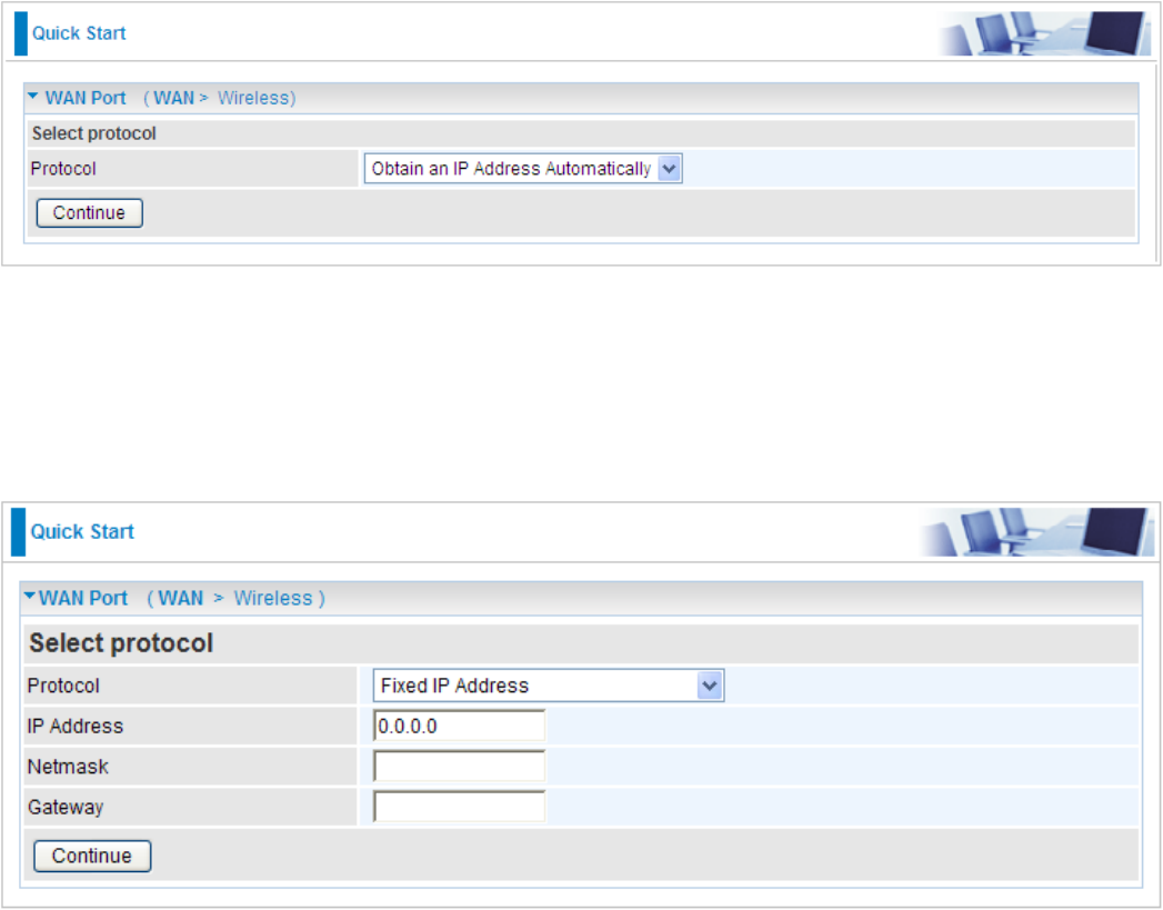
WAN Connect Mode
There are 4 types of wireless connect modes: Obtain an IP Address Automatically, Fixed IP
Address, PPPoE connection and Pure Bridge.
Obtain an IP Address Automatically
When connecting to the ISP, your router also functions as a DHCP client. The device can
automatically obtain an IP address, subnet mask, gateway address, and DNS server addresses if
the ISP assigns this information via DHCP.
Select this protocol enables the device to automatically retrieve IP address.
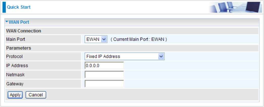
Fixed IP Address
Select this option to set static IP information. You will need to enter the information provided to you
by your ISP.
IP Address: Enter your xed IP address. Each IP address entered must be in the appropriate IP
form, which is four IP octets separated by a dot (x.x.x.x). The Router will not accept the IP address
if it is not in this format. Leave the IP address as 0.0.0.0 to enable the device to automatically
obtain an IP address from your ISP.
Netmask: User can change it to others such as 255.255.255.128. Type the netmask assigned to
you by your ISP (if given).
Gateway: Enter the IP address of the default gateway.
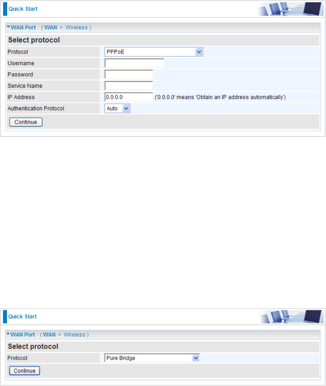
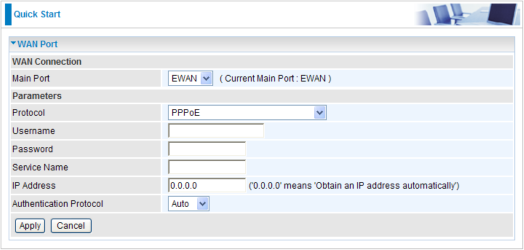
PPPoE
PPPoE (PPP over Ethernet) provides access control in a manner which is similar to dial-up services
using PPP.
Username: Enter the username provided by your ISP. You can input up to 256 alphanumeric
characters (case sensitive). This is the format of username “username@ispname” instead of
“username”.
Password: Enter the password provided by your ISP. You can input up to 32 alphanumeric
characters (case sensitive).
Service Name: This item is for identication purposes. If it is required, your ISP will provide you
the necessary information. Maximum input is 32 alphanumeric characters.
IP Address: Enter your xed IP address. Leave the IP address as 0.0.0.0 to enable the device to
automatically obtain an IP address from your ISP.
Authentication Protocol: Default is Auto. Please consult your ISP on whether to use Pap or
Chap.
Pure Bridge
30
31
Wireless Setting Mode
There are 4 types of wireless security modes: WPA Pre-Shared Key, WPA2 Pre-Shared Key,
WPA/WPA2 Pre-Shared Key and WEP.
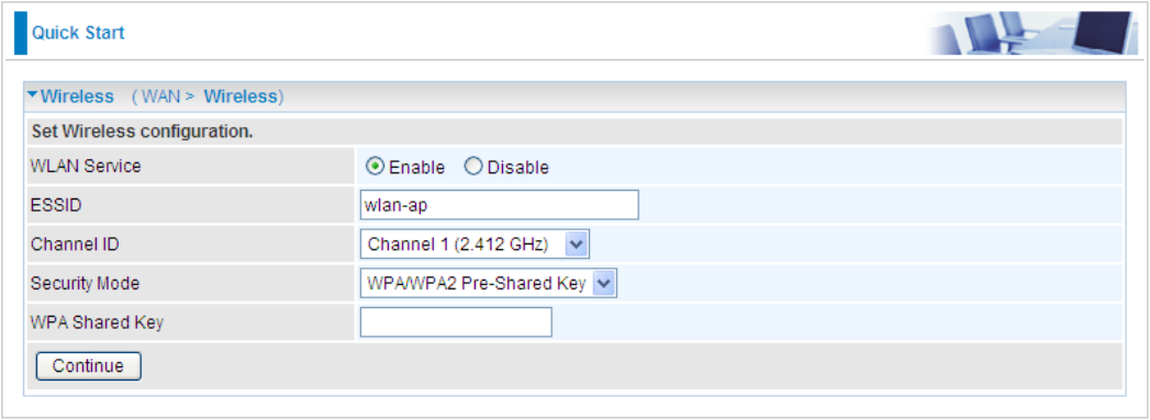
WPA / WPA2 / WPA/WPA2 Pre-Shared Key
WPA and WPA2 pre-shared keys are an authentication mechanism in which users provide some
form of credentials to verify that they should be allowed access to a network. This requires a
single password entered into each WLAN node (Access Points, Wireless Routers, client adapters,
bridges). As long as the passwords match, a client will be granted access to a WLAN.
WLAN Service: Default setting is Enable. If you want to use wireless, you can select Enable.
ESSID: The ESSID is the unique name of a wireless access point (AP) used to distinguish one
from another. For security propose, change to a unique ID name which is already built into the
router wireless interface. It is case sensitive and must not exceed 32 characters. Make sure your
wireless clients have exactly the ESSID as the device in order to connect to your network.
Channel ID: Select the channel ID that you would like to use.
Security Mode: You can disable or enable with WPA or WEP to protect wireless network. The
default mode of wireless security is Disable.
WPA Shared Key: The key for network authentication. The input format is in character style and
key size should be in the range between 8 and 63 characters.
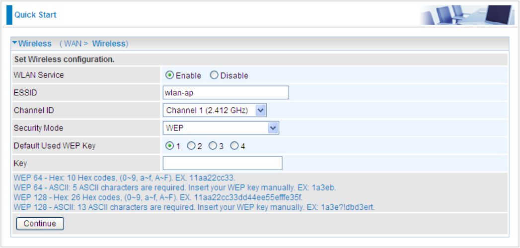
WEP
WLAN Service: Default setting is set to Enable. If you want to use wireless, you can select
Enable.
ESSID: The ESSID is the unique name of a wireless access point (AP) used to distinguish one
from another. For security propose, change to a unique ID name which is already built into the
router wireless interface. It is case sensitive and must not exceed 32 characters. Make sure your
wireless clients have exactly the ESSID as the device in order to connect to your network.
Channel ID: Select the channel ID that you would like to use.
Security Mode: You can disable or enable with WPA or WEP to protect wireless network. The
default mode of wireless security is Disable.
Default Used WEP Key: Select the encryption key ID; please refer to Key (1~4) below.
Key (1-4): Enter the key to encrypt wireless data. To allow encrypted data transmission, the WEP
Encryption Key values on all wireless stations must be the same as the router. There are four keys
for your selection. The input format can either be HEX style or ASCII format, 10 and 26 HEX codes
or 5 and 13 ASCII codes are required for WEP64 and WEP128 respectively.
32
33
Basic Conguration Mode
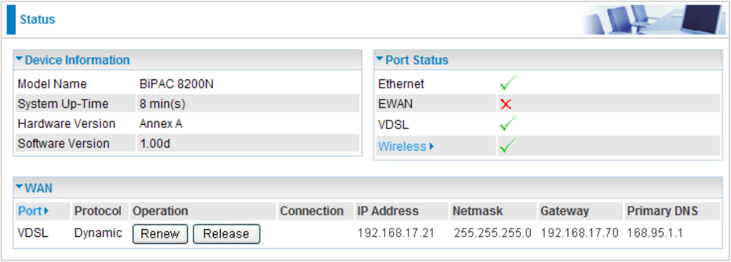
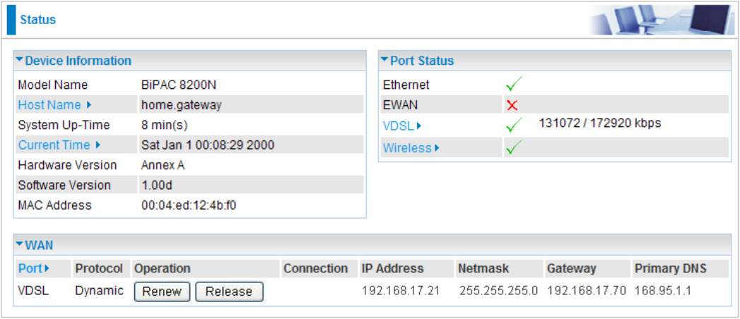
Status
Device Information
Model Name: Provide a name for the router for identication purposes.
System Up-Time: Record system up-time.
Hardware Version: Device version.
Software Version: Firmware version.
Port Status
Port Status: User can look up to see if they are connected to Ethernet, EWAN, VDSL and
Wireless. You are allowed to click Wireless link to go to Wireless Parameters conguration screen.
WAN
Port: Name of the WAN connection. You are allowed to click this link to go to WAN Connection
conguration screen.
Protocol: The current protocol in the device.
Operation: Current status in WAN interface.
Connection: Current connection status.
IP Address: WAN port IP address.
Netmask: WAN port IP subnet mask.
Gateway: IP address of the default gateway.
Primary DNS: IP address of the primary DNS server.
34
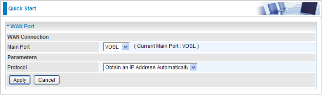
WAN – Main Port: VDSL
A WAN (Wide Area Network) is an outside connection to another network or the Internet.
Obtain IP Address Automatically (VDSL)
By conguring these settings, the device is able to obtain IP settings automatically from the ISP.
Protocol: Select the protocol you will use in the device.
Click Apply to conrm the settings.
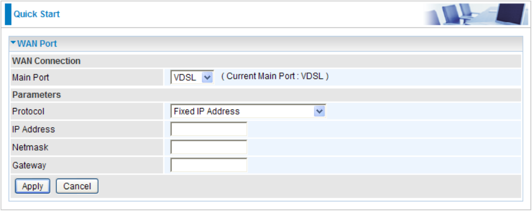
Fixed IP Address (VDSL)
A Static WAN connection will be congured according to the IP properties dened by your ISP.
Protocol: Select the protocol you will use in the device.
IP Address: Enter your xed IP address.
Netmask: User can change it to others such as 255.255.255.128. Type the netmask assigned to
you by your ISP (if given).
Gateway: Enter the IP address of the default gateway (if given).
Click Apply to conrm the settings.
35
36
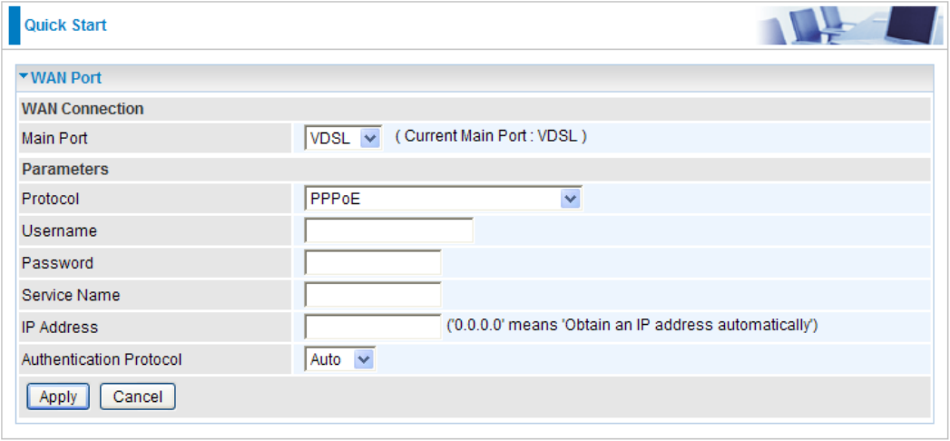
PPPoE Connection (VDSL)
PPPoE (PPP over Ethernet) provides access control in a manner which is similar to dial-up services
using PPP.
Protocol: Select the protocol you will use in the device.
Username: Enter the username provided by your ISP. You can input up to 256 alphanumeric
characters (case sensitive).
Password: Enter the password provided by your ISP. You can input up to 32 alphanumeric
characters (case sensitive).
Service Name: This item is for identication purposes. If it is required, your ISP will provide you
the necessary information. Maximum input is 32 alphanumeric characters.
IP Address: Enter your WAN IP address. Leave the IP address empty or enter 0.0.0.0 to enable
the device to automatically obtain an IP address from your ISP.
Authentication Protocol: Default is Auto. Please consult your ISP on whether to use Pap and
Chap.
Click Apply to conrm the settings.

Pure Bridge (VDSL)
Protocol: Select the protocol you will use in the device.
Click Apply to conrm the change.
37
38
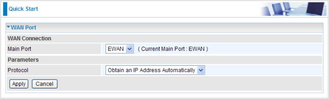
WAN – Main Port: EWAN
A WAN (Wide Area Network) is an outside connection to another network or the Internet.
Obtain IP Address Automatically (EWAN)
By conguring these settings, the device is able to obtain IP settings automatically from the ISP.
Protocol: Select the protocol you will use in the device.
Click Apply to conrm the settings.
Fixed IP Address (EWAN)
A Static WAN connection will be congured according to the IP properties dened by your ISP.
Protocol: Select the protocol you will use in the device.
IP Address: Enter your xed IP address. Leave the IP address as 0.0.0.0 to enable the device to
automatically obtain an IP address from your ISP.
Netmask: User can change it to others such as 255.255.255.128. Type the netmask assigned to
you by your ISP (if given).
Gateway: Enter the IP address of the default gateway (if given).
Click Apply to conrm the settings.
39
40
PPPoE Connection (EWAN)
PPPoE (PPP over Ethernet) provides access control in a manner which is similar to dial-up services
using PPP.
Protocol: Select the protocol you will use in the device.
Username: Enter the username provided by your ISP. You can input up to 256 alphanumeric
characters (case sensitive).
Password: Enter the password provided by your ISP. You can input up to 32 alphanumeric
characters (case sensitive).
Service Name: This item is for identication purposes. If it is required, your ISP will provide you
the necessary information. Maximum input is 32 alphanumeric characters.
IP Address: Enter your WAN IP address. Leave the IP address as 0.0.0.0 to enable the device to
automatically obtain an IP address from your ISP.
Auth. Protocol: Default is Auto. Please consult your ISP on whether to use Pap and Chap.
Click Apply to conrm the settings.
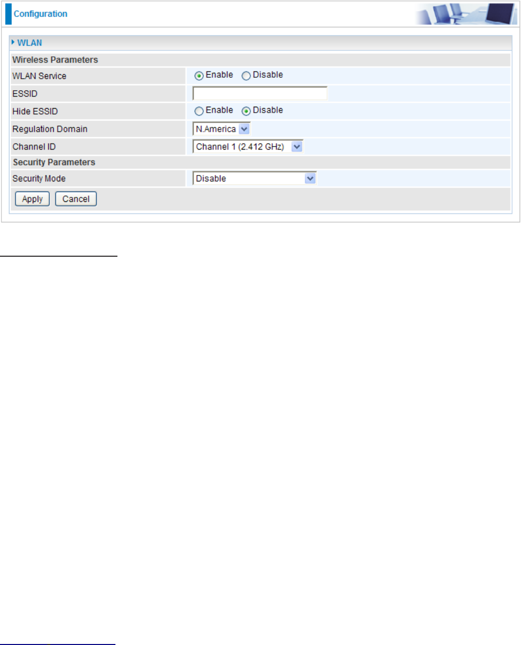
WLAN
Wireless Parameters
WLAN Service: Default setting is set to Enable. If you do not have any wireless, select Disable.
ESSID: The ESSID is a unique name of a wireless access point (AP) used to distinguish one from
another. For security purpose, change the default wlan-ap to a unique ID name that is already
built into the router wireless interface. Make sure your wireless clients have exactly the ESSID as
the device in order to connect to your network.
Note: It is case sensitive and must not exceed 32 characters.
Hide ESSID: It is used to broadcast its ESSID on the network so that when a wireless client
searches for a network, the router can be discovered and recognized. Default setting is Disable.
Enable: When enabled, you do not broadcast your ESSID. Therefore, no one will be able to
locate the Access Point (AP) of your router.
Disable: When disabled, you allow anybody with a wireless client to be able to locate the
Access Point (AP) of your router.
Regulation Domain: There are seven Regulation Domains for you to choose from, including
North America (N.America), Europe, France, etc. The Channel ID will be different based on this
setting.
Channel ID: Select the wireless connection channel ID that you would like to use.
Note: Wireless performance may degrade if the selected channel ID is already being occupied
by other AP(s).
Security Parameters
Security Mode: You can disable or enable the function with WPA or WEP to protect the wireless
network. The default mode of wireless security is Disable.
Click Apply to conrm the settings.
41
42
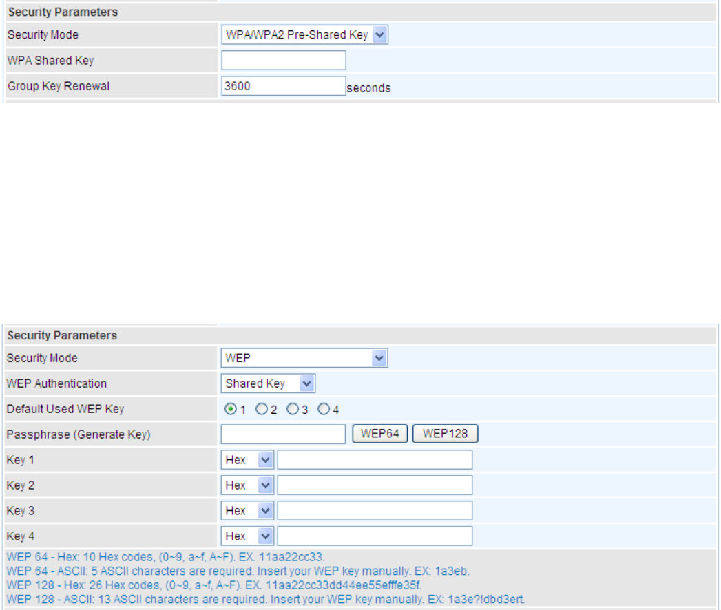
Security Mode
WPA / WPA2 / WPA/WPA2 Pre-Shared Key
Security Mode: You can disable or enable with WPA or WEP for protecting wireless network.
WPA Shared Key: The key for network authentication. The input format is in character style and
key size should be in the range between 8 and 63 characters.
Group Key Renewal: The period of renewal time for changing the security key automatically
between wireless client and Access Point (AP). Default value is 3600 seconds.
WEP
Security Mode: You can disable or enable with WPA or WEP for protecting wireless network.
WEP Authentication: To prevent unauthorized wireless stations from accessing data transmitted
over the network, the router offers secure data encryption, known as WEP. If you require high
security for transmissions, there are 3 options to select from: Open System, Share Key and Both.
Default Used WEP Key: Select the encryption key ID; please refer to Key (1~4) below.
Passphrase: This is used to generate WEP keys automatically based upon the input string and a
pre-dened algorithm in WEP64 or WEP128.
Key (1-4): Enter the key to encrypt wireless data. To allow encrypted data transmission, the WEP
Encryption Key values on all wireless stations must be the same as the router. There are four keys
for your selection. The input format is in HEX or ASCII style, 5 and 13 ASCII codes are required for
WEP64 and WEP128 or 10 and 26 HEX codes are required for WEP64 and WEP128 respectively.
43
Advanced Conguration Mode
Status
Device Information
Model Name: Displays the model name.
Host Name: Provide a name for the router for identication purposes. Host Name lets you change
the router name.
System Up-Time: Records system up-time.
Current Time: Set the current time. See the Time Zone section for more information.
Hardware Version: Device version.
Software Version: Firmware version.
MAC Address: The LAN MAC address.
Port Status
Port Status: User can look up to see if they are connected to Ethernet, EWAN, VDSL and
Wireless. You are allowed to click VDSL and Wireless link to go to VDSL Status screen or Wireless
Parameters conguration screen.
WAN
Port: Name of the WAN connection.
Protocol: The current protocol in the device.
Operation: The current status in WAN interface.
44
Connection: The current connection status.
IP Address: WAN port IP address.
Netmask: WAN port IP subnet mask.
Gateway: The IP address of the default gateway.
Primary DNS: The IP address of the primary DNS server.
45
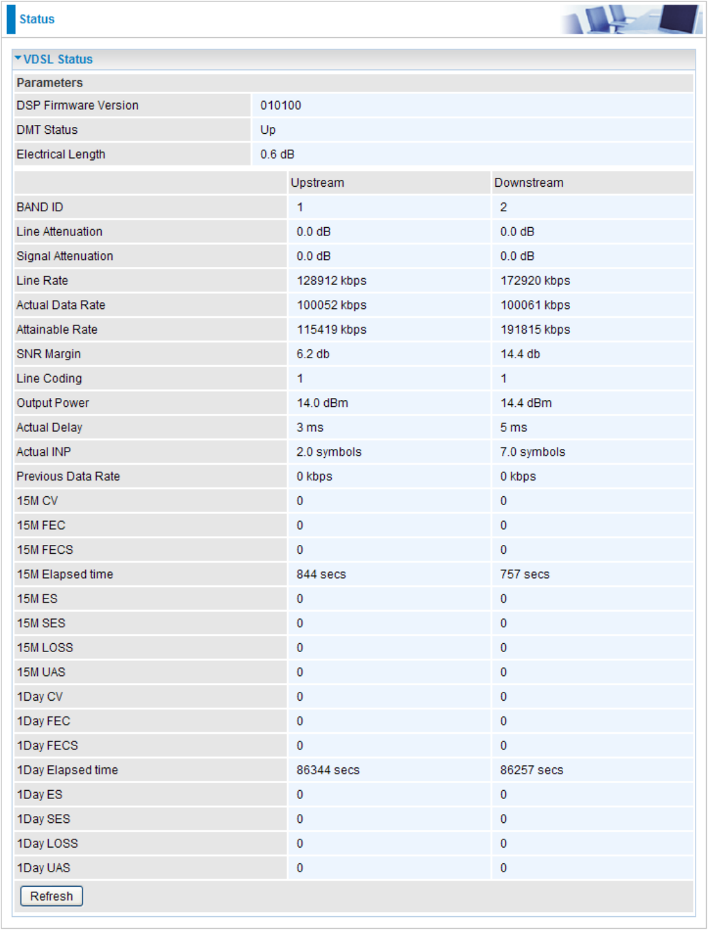
VDSL Status
VDSL (Very High Bitrate DSL) is a DSL technology providing faster data transmission. It can
achieve incredible speeds and provides a complete home-communications/entertainment
package.
This table displays all the informaiton for VDSL connection.
46
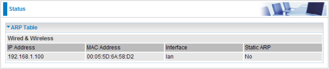
ARP Table
This table stores mapping information that the device uses to nd the Layer 2 Media Access
Control (MAC) address that corresponds to the Layer 3 IP address of the device via the Address
Resolution Protocol (ARP) feature.
IP Address: Shows the IP Address of the device that the MAC address maps to.
MAC Address: Shows the MAC address that is corresponded to the IP address of the device it is
mapped to.
Interface: Shows the interface name (on the router) that this IP address connects to.
Static ARP: Shows the status of static ARP.
47
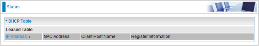
DHCP Table
The DHCP Table lists the DHCP lease information for all IP addresses assigned by the DHCP
server in the device.
IP Address: The IP address which is assigned to the host with this MAC address.
MAC Address: The MAC Address of internal dhcp client host.
Client Host Name: The Host Name of internal dhcp client.
Register Information: Shows the information provided during registration.
48
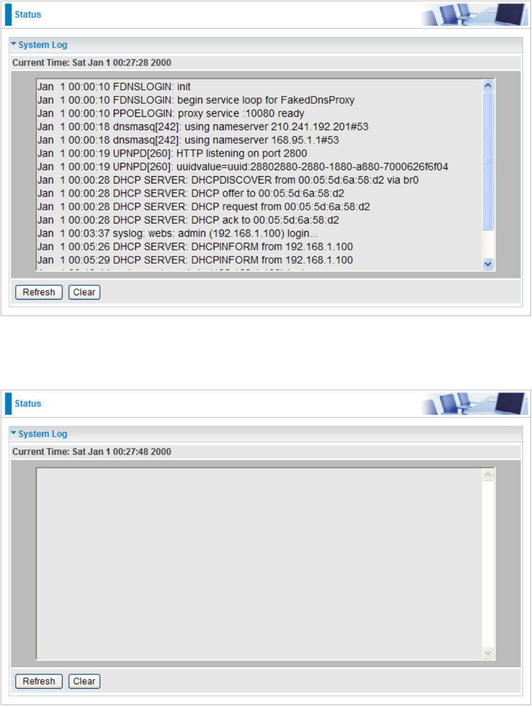
System Log
Display system logs accumulated up to the present time. You can trace its historical information
with this function.
Refresh: Click to update the system log.
Clear: Click to clear the current log from the screen.
49
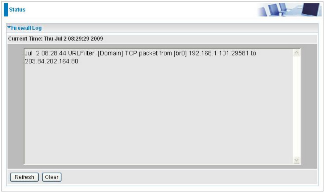
Firewall Log
Firewall Log displays the log information of any unexpected events that occurs to your rewall
settings. This page displays the router Firewall Log entries which have been recorded when you
have enabled Intrusion Detection or Block WAN PING in the Conguration – Firewall section of the
interface. Please see the Firewall section of this manual for more details on how to enable Firewall
event logging.
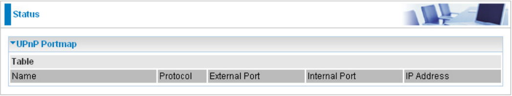
UPnP Portmap
This section lists all the established port-mapping using UPnP (Universal Plug and Play).
Name: The Host Name of the internal UPNP client.
Protocol: The connection protocol of the UPNP client.
External Port: The external port for this connection.
Internal Port: The internal port for this connection.
IP Address: IP of the internal UPNP client.
50
51
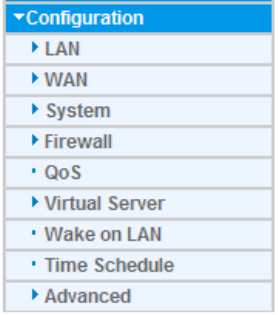
Conguration
When you click this item, the column will expand to display the sub-items that will allow you to further
congure your router.
LAN, WAN, System, Firewall, QoS, Virtual Server, Wake on LAN, Time Schedule and
Advanced.
The function of each conguration sub-item is described in the following sections.
LAN - Local Area Network
A Local Area Network (LAN) is a shared communication system network where many computers
are connected. This type of network is area dened and is usually limited to a conned region
within a building or just within the same storey of a building.
There are 6 items within the LAN section: Ethernet, IP Alias, Wireless, Wireless Security, WPS
and DHCP Server.
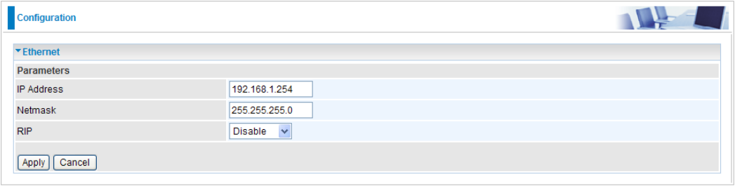
Ethernet
The router supports more than one Ethernet IP addresses in the LAN that supports multiple internet
access at the same time. Users usually only have one subnet in their LAN. The default IP address
for the router is 192.168.1.254.
IP Address: The default IP on this router.
Netmask: The default subnet mask on this router.
RIP: RIP v1, RIP v2 Broadcast, RIP v2 Multicast and RIP v1+v2 Broadcast. Check to enable RIP
function.
Click Apply to conrm the settings.
52
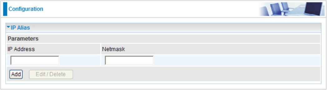
IP Alias
This function allows the addition an IP alias to the network interface. It further allows user the
exibility to assign a specic function to use this IP.
IP Address: Enter the IP address to be added to the network.
Netmask: Specify a subnet mask for the IP to be added.
Click Apply to conrm the settings.
53
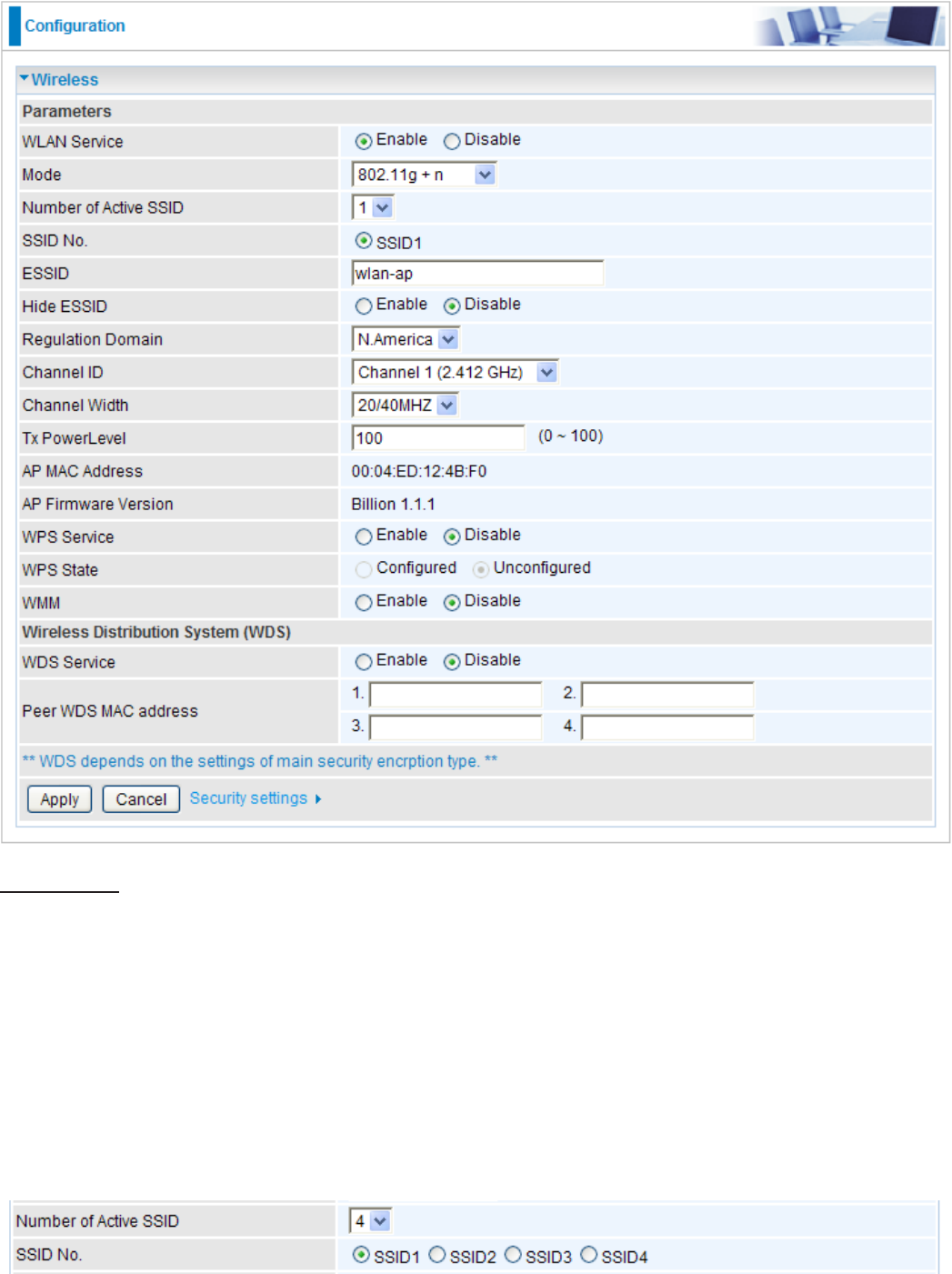
Wireless
Parameters
WLAN Service: Default setting is set to Enable. If you do not have any wireless, select Disable.
Mode: The default setting is 802.11g+n. If you do not know or have both 11g and 11b devices in
your network, then keep the default in mixed mode. From the drop-down manual, you can select
802.11g if you have only 11g card. If you have only 11b card, then select 802.11b. And if you have
11n card, you can select 802.11n.
Number of Active SSID: You can select 1, 2, or 4 SSIDs to be available at the same time.
SSID No.: The selection of SSIDs will depend on the Number of Active SSID. Select each SSID,
ranging from SSID1, SSID2, SSID3 and SSID4 and set their individual congurations.
54

ESSID: The ESSID is the unique name of a wireless access point (AP) used to distinguish one
from another. For security propose, change to a unique ID name which is already built into the
router wireless interface. It is case sensitive and must not exceed 32 characters. Make sure your
wireless clients have exactly the ESSID as the device in order to connect to your network.
Hide ESSID: This function enables the router to become invisible on the network. Thus, any
clients using the wireless setting to search for available or specic router on the network will not
be able to discover the router whose Hide ESSID function is set to enabled. The default setting is
disabled.
Enable: When enabled, you do not broadcast your ESSID. Therefore, no one will be able to
locate the Access Point (AP) of your router.
Disable: When disabled, you allow anybody with a wireless client to be able to locate the
Access Point (AP) of your router.
Regulation Domain: There are seven Regulation Domains for you to choose from, including
North America (N.America), Europe, France, etc. The Channel ID will be different based on this
setting.
Channel ID: Select the wireless connection channel ID that you would like to use.
Note: Wireless performance may degrade if the selected channel ID is already being
occupied by other AP(s).
Channel Width: Select either 20 MHz or 20/40 MHz for the channel bandwidth. The higher the
bandwidth the better the performance will be.
TX PowerLevel: It is a function that enhances the wireless transmitting signal strength. User
may adjust this power level from minimum 0 up to maximum 100.
Note: The Power Level maybe different in each access network user premise environment,
choose the most suitable level for your network.
AP MAC Address: It is a unique hardware address of the Access Point.
AP Firmware Version: The Access Point rmware version.
WPS Service: Select Enable if you would like to activate WPS service.
WPS State: This column allows you to set the status of the device wireless setting whether it
has been congured or uncongured. For WPS conguration please refer to the section on Wi-Fi
Network Setup for detail.
WMM: This feature is used to control the prioritization of trafc according to 4 Access categories:
Voice, Video, Best Effort and Background. Default is set to disable.
Wireless Distribution System (WDS)
It is a wireless access point mode that enables wireless link and communication with other access
points. It is easy to install simply by dening the peer’s MAC address of the connected AP. WDS
takes advantages of the cost saving and exibility which no extra wireless client device is required
to bridge between two access points and extending an existing wired or wireless infrastructure
network to create a larger network. It can connect up to 4 wireless APs for extending cover range
at the same time.
In addition, WDS also enhances its link connection security mode. Key encryption and channel
must be the same for both access points.
55
56
WDS Service: The default setting is disabled. Check Enable radio button to activate this function.
1. Peer WDS MAC Address: It is the associated AP’s MAC Address. It is important that your
peer’s AP must include your MAC address in order to acknowledge and communicate with
each other.
2. Peer WDS MAC Address: It is the second associated AP’s MAC Address.
3. Peer WDS MAC Address: It is the third associated AP’s MAC Address.
4. Peer WDS MAC Address: It is the fourth associated AP’s MAC Address.
Note: For MAC Address, the format can be: xx:xx:xx:xx:xx:xx or xx-xx-xx-xx-xx-xx.
Click Apply to conrm the settings.
You can click Security settings link next to Cancel button to go to Wireless Security screen (see
Wireless Security section).
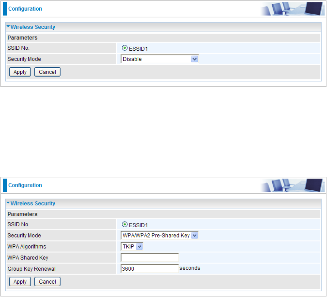
Wireless Security
You can disable or enable wireless security function using WPA or WEP for protecting wireless
network. The default mode of wireless security is disabled.
SSID No.: The selection of SSIDs will depend on the Number of Active SSID set on Wireless
screen.
Security Mode: Select the security mode from the drop-down menu, there are Disable, WPA Pre-
Shared Key, WPA2 Pre-Shared Key, WPA/WPA2 Pre-Shared Key and WEP.
WPA / WPA2 / WPA/WPA2 Pre-Shared Key
Security Mode: You can choose the type of security mode you want to apply from the drop-down
menu.
WPA Algorithms: There are 3 types of the WPA-PSK, WPA2-PSK and WPA/WPA2-PSK.
The WPA-PSK adapts the TKIP (Temporal Key Integrity Protocol) encrypted algorithms, which
incorporates Message Integrity Code (MIC) to provide protection against hackers. The WPA2-
PSK adapts CCMP (Cipher Block Chaining Message Authentication Code Protocol) of the AES
(Advanced Encryption Security) algorithms.
WPA Shared Key: The key for network authentication. The input format is in character style and
key size should be in the range between 8 and 63 characters.
Group Key Renewal: The period of renewal time for changing the security key automatically
between wireless client and Access Point (AP). Default value is 3600 seconds.
Click Apply to conrm the settings.
57
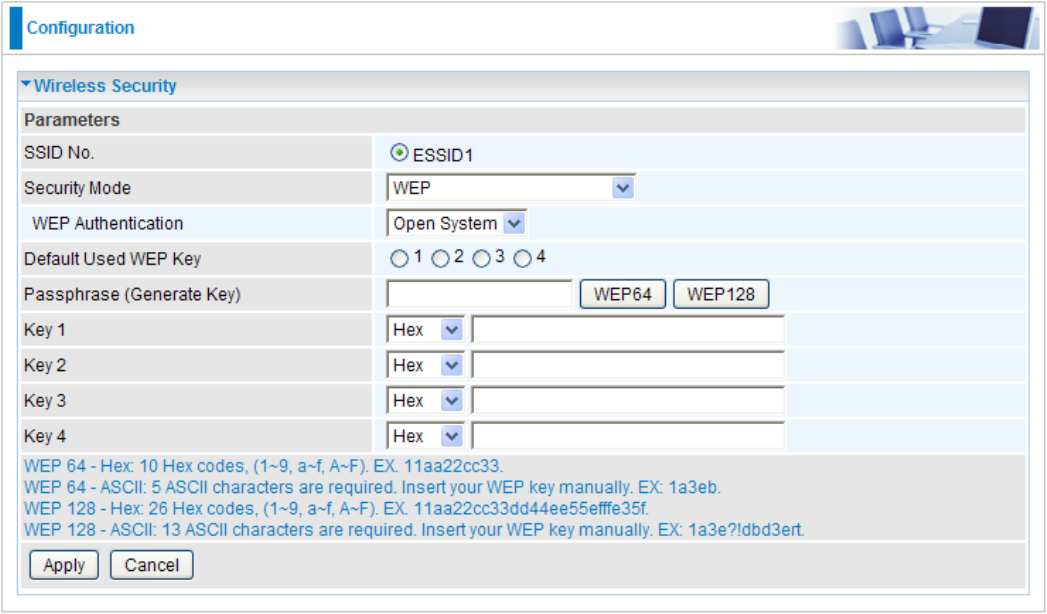
WEP
Security Mode: Choose the type of security mode WEP from the drop-down menu.
WEP Authentication: To prevent unauthorized wireless stations from accessing data transmitted
over the network, the router offers secure data encryption, known as WEP. There are 3 options to
select from: Open System, Shared Key or Both.
Default Used WEP Key: Select the encryption key ID; please refer to Key (1~4) below.
Passphrase: This is used to generate WEP keys automatically based upon the input string and a
pre-dened algorithm in WEP64 or WEP128.
Key (1~4): Enter the key to encrypt wireless data. To allow encrypted data transmission, the WEP
Encryption Key values on all wireless stations must be the same as the router. There are four keys
for your selection. The input format is in HEX or ASCII style, 5 and 13 ASCII codes are required for
WEP64 and WEP128 or 10 and 26 HEX codes are required for WEP64 and WEP128 respectively.
Click Apply to conrm the settings.
58
WPS
WPS (WiFi Protected Setup) feature is a standard protocol created by Wi-Fi Alliance. This feature
greatly simplies the steps needed to create a Wi-Fi networks for a residential or an ofce setting.
WPS supports 2 types of conguration methods which are commonly known among consumers:
PIN Method & PBC Method.
59
Wi-Fi Network Setup
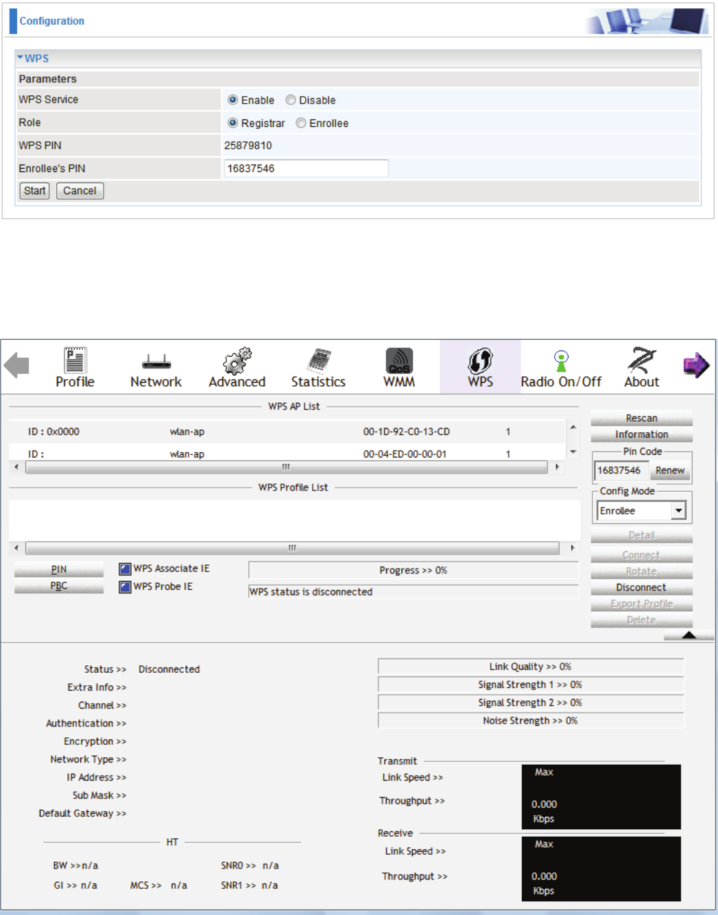
PIN Method: Congure AP as Registrar
1. Jot down the client’s Pin (eg. 16837546).
2. Enter the Enrollee’s PIN number and then press Start.
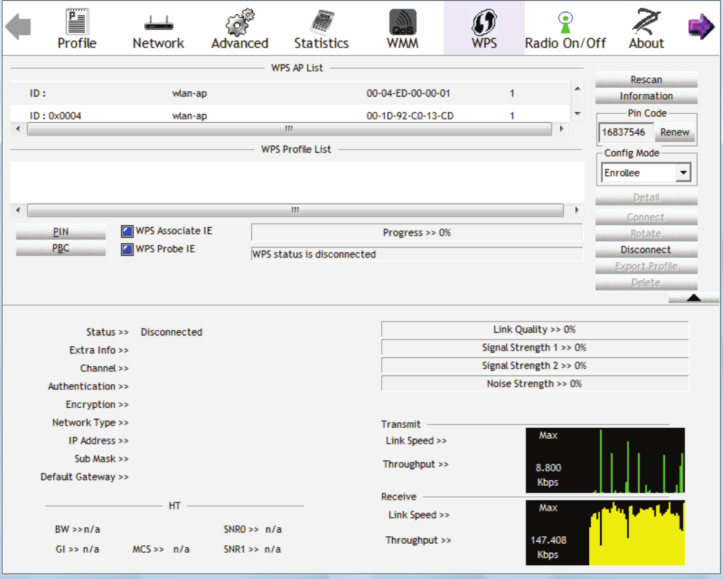
3. Launch the wireless client’s WPS utility (eg. Ralink Utility). Set the Cong Mode as Enrollee,
press the WPS button on the top bar, select the AP (eg. wlan-ap) from the WPS AP List column.
Then press the PIN button located on the middle left of the page to run the scan.
60
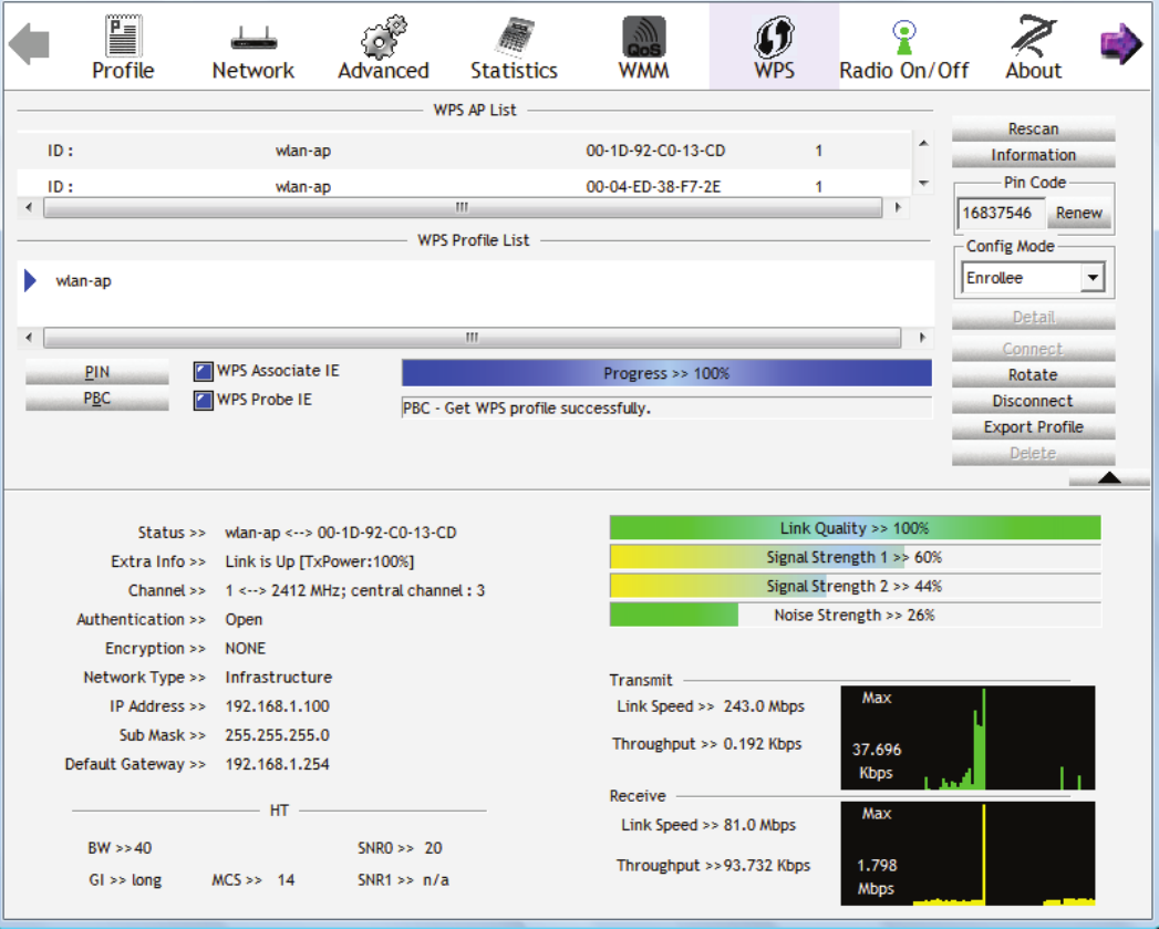
4. The client’s SSID and security setting will now be congured to match the SSID and security
setting of the registrar.
61
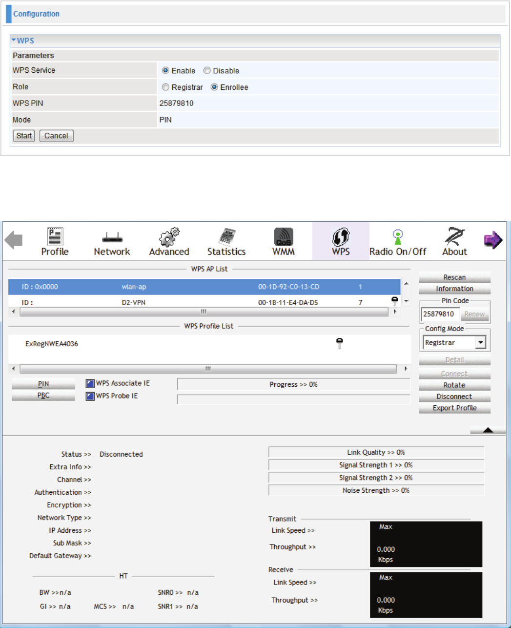
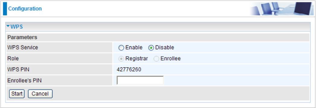
PIN Method: Congure AP as Enrollee
1. In the WPS conguration page, change the Role to Enrollee. Then press Start.
2. Jot down the WPS PIN (eg. 25879810).
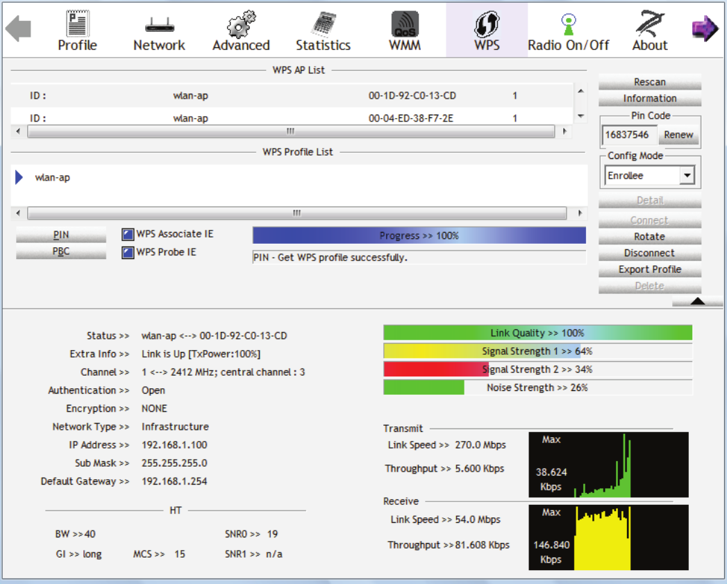
3. Launch the wireless client’s WPS utility (eg. Ralink Utility). Set the Cong Mode as Registrar.
Enter the PIN number in the PIN Code column then choose the correct AP (eg. wlan-ap) from
the WPS AP List section before pressing the PIN button to run the scan.
62
63
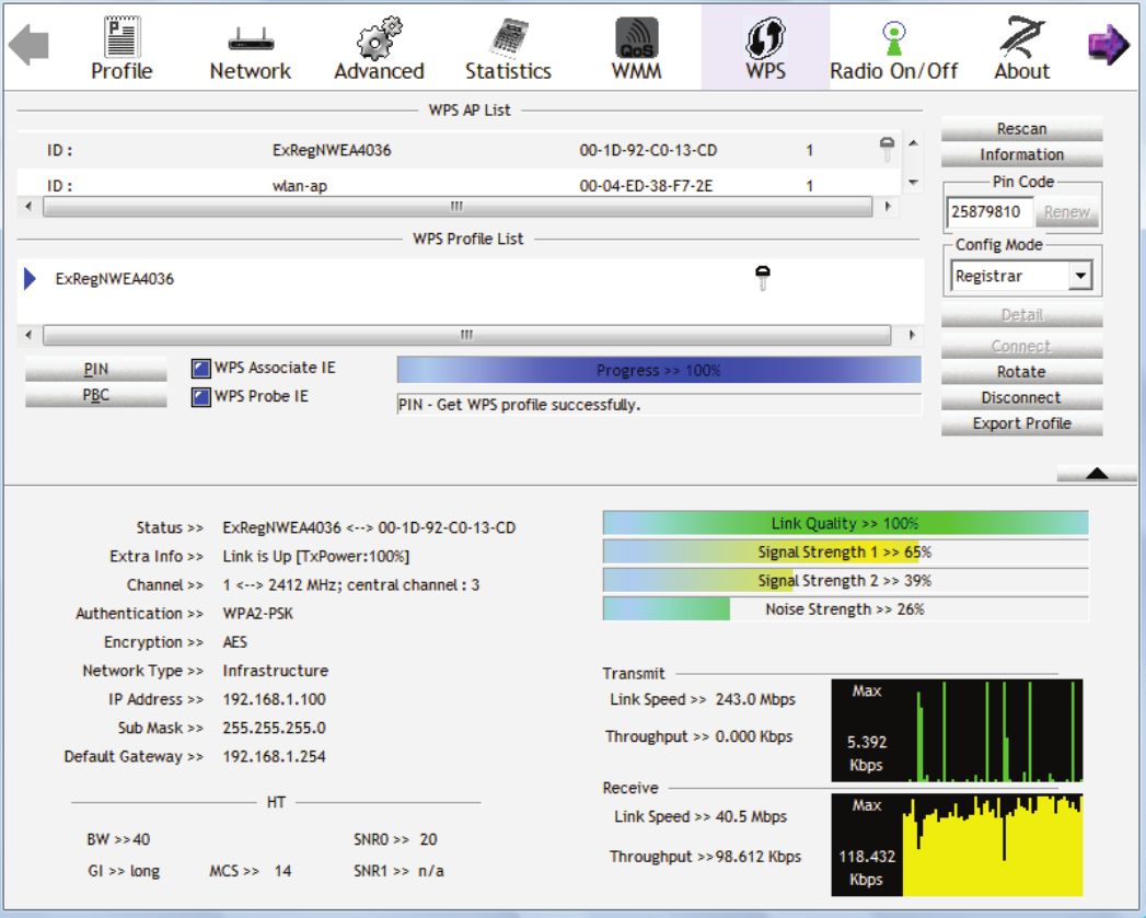
4. The router’s (AP’s) SSID and security setting will now be congured to match the SSID and
security setting of the registrar.
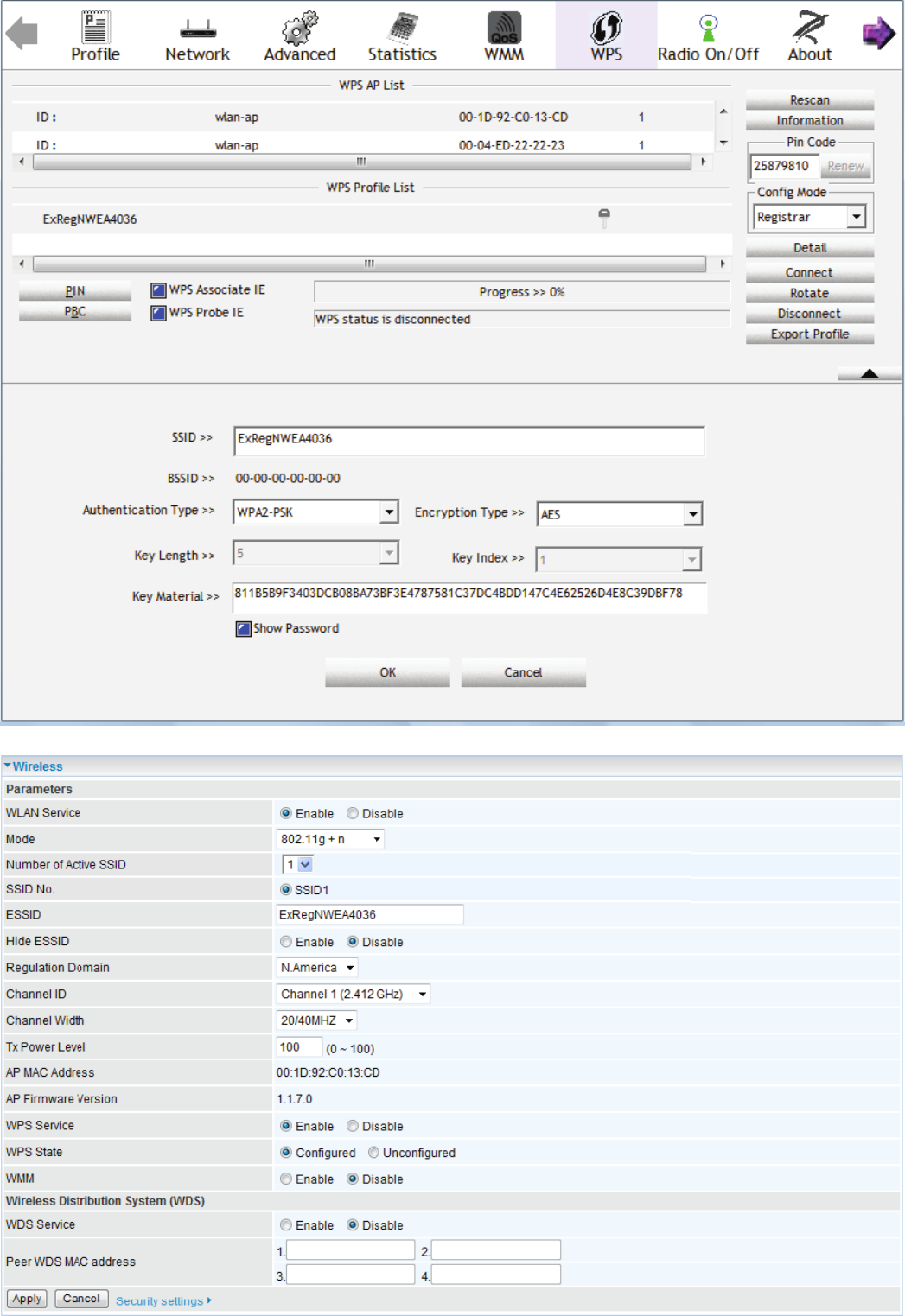
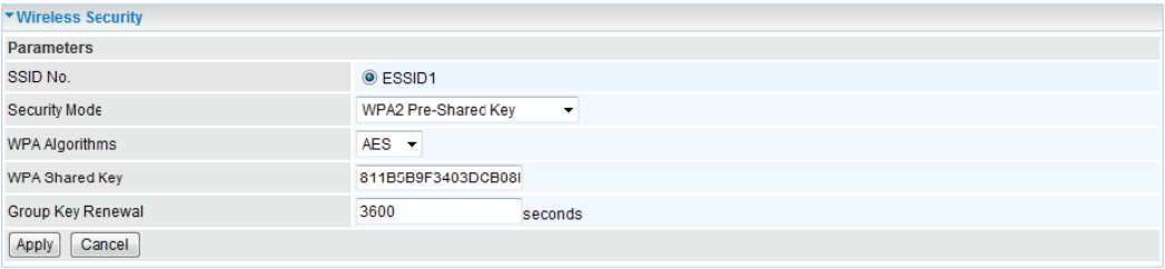
5. Now to make sure that the setup is correctly done, cross check to see if the SSID and the security
setting of the registrar setting match with the parameters found on both Wireless Conguration
and Wireless Security Conguration page.
64
65
66
PBC Method:
1. Press the PBC button of the AP.
2. Launch the wireless client’s WPS Utility (eg. Ralink Utility). Set the Cong Mode as Enrollee.
Then press the WPS button and choose the correct AP (eg. wlan-ap) from the WPS AP List
section before pressing the PBC button to run the scan.
67
3. When the PBC button is pushed, a wireless communication will be established between your
router and the PC. The client’s SSID and security setting will now be congured to match the
SSID and security setting of the router.
68
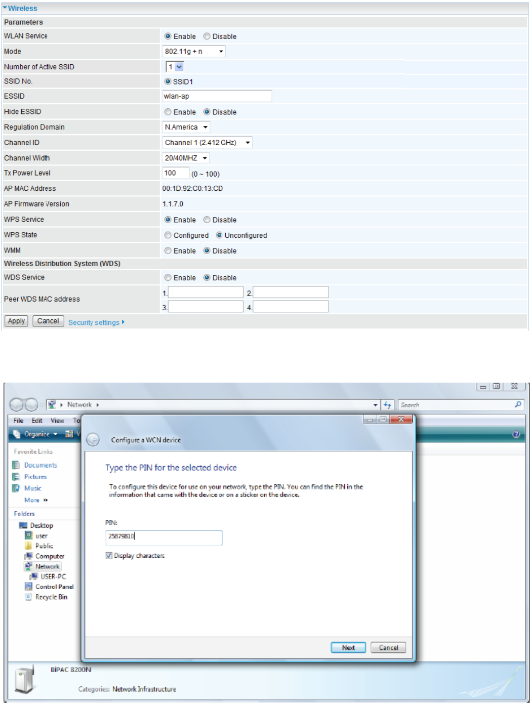
Wi-Fi Network Setup with Windows Vista WCN:
1. Jot down the AP PIN from the Web (eg. 25879810).
2. Access the Wireless conguration of the web GUI. Set the WPS State to Uncongured then
click Apply.
3. In your Vista operating system, access the Control Panel page, then select Network and Internet
> View Network Computers and Devices. Double click on the BiPAC 8200N icon and enter the
AP PIN in the column provided then press Next.