Billion Electric BIL-8920NX600 Dual-lines VDSL2/ADSL2+ Wireless-N 600Mbps 3G/4G LTE VPN Firewall Router User Manual 1
Billion Electric Co., Ltd. Dual-lines VDSL2/ADSL2+ Wireless-N 600Mbps 3G/4G LTE VPN Firewall Router Users Manual 1
Contents
- 1. Users Manual-1
- 2. Users Manual-2
- 3. Users Manual-3
Users Manual-1

BiPAC 8920NX(L)-600
Dual-lines VDSL2/ADSL2+
Wireless 600Mbps 3G/4G LTE (VPN)
Firewall Router
User Manual
Version Released: 2.50a.dt1
Last revised date: May 27, 2015
Table of Contents
Chapter1:Introduction .................................................................................................................................. 1
IntroductiontoyourRouter..................................................................................................................... 1
Features ................................................................................................................................................... 3
VDSL2/ADSL2+Compliance .............................................................................................................. 3
NetworkProtocolsandFeatures ...................................................................................................... 4
Firewall.............................................................................................................................................. 4
QualityofServiceControl ................................................................................................................. 5
ATMandPPPProtocols .................................................................................................................... 5
IPTVApplications .............................................................................................................................. 5
WirelessLAN ..................................................................................................................................... 5
USBApplicationServer ..................................................................................................................... 6
VirtualPrivateNetwork(VPN)(BiPAC8920NX‐600only) ................................................................ 6
Management..................................................................................................................................... 6
HardwareSpecifications .......................................................................................................................... 7
PhysicalInterface.............................................................................................................................. 7
Chapter2:InstallingtheRouter...................................................................................................................... 8
PackageContents..................................................................................................................................... 8
Importantnoteforusingthisrouter ....................................................................................................... 9
DeviceDescription ................................................................................................................................. 10
TheFrontLEDs ................................................................................................................................ 10
TheRearPorts................................................................................................................................. 11
Cabling.................................................................................................................................................... 12
Chapter3:BasicInstallation ......................................................................................................................... 13
ConnectingYourRouter......................................................................................................................... 14
NetworkConfiguration .......................................................................................................................... 17
ConfiguringaPCinWindows7/8 .................................................................................................. 17
ConfiguringaPCinWindowsVista................................................................................................. 20
ConfiguringaPCinWindowsXP..................................................................................................... 23
FactoryDefaultSettings......................................................................................................................... 25
InformationfromyourISP ..................................................................................................................... 27
EasySignOn(EZSO) ...................................................................................................................................... 28
Chapter4:Configuration .............................................................................................................................. 35
ConfigurationviaWebInterface............................................................................................................ 35
Status ..................................................................................................................................................... 37
Summary ......................................................................................................................................... 38
WAN ................................................................................................................................................ 39
Statistics .......................................................................................................................................... 40
LAN........................................................................................................................................... 40
Reset:Pressthisbuttontorefreshthestatistics..................................................................... 40
WANService............................................................................................................................. 41
xTM .......................................................................................................................................... 42
xDSL.......................................................................................................................................... 42
BandwidthUsage ............................................................................................................................ 46
LAN........................................................................................................................................... 46
WANService............................................................................................................................. 48
3G/4GLTEStatus ............................................................................................................................ 50
Route............................................................................................................................................... 51
ARP.................................................................................................................................................. 52
DHCP ............................................................................................................................................... 53
VPN(BiPAC8920NX‐600only)........................................................................................................ 54
IPSec......................................................................................................................................... 54
PPTP ......................................................................................................................................... 55
L2TP.......................................................................................................................................... 56
GRE........................................................................................................................................... 57
Log................................................................................................................................................... 58
SystemLog ............................................................................................................................... 58
SecurityLog.............................................................................................................................. 59
QuickStart.............................................................................................................................................. 60
QuickStart....................................................................................................................................... 60
Configuration ......................................................................................................................................... 66
LAN‐LocalAreaNetwork ............................................................................................................... 67
Ethernet ................................................................................................................................... 67
IPv6Autoconfig........................................................................................................................ 70
InterfaceGrouping................................................................................................................... 74
Wireless........................................................................................................................................... 77
Basic ......................................................................................................................................... 78
Security .................................................................................................................................... 80
MACFilter ................................................................................................................................ 91
WirelessBridge ........................................................................................................................ 92
Advanced ................................................................................................................................. 93
StationInfo............................................................................................................................... 95
ScheduleControl...................................................................................................................... 96
WAN‐WideAreaNetwork............................................................................................................... 97
WANService............................................................................................................................. 97
DSL97
Ethernet .......................................................................................................................... 108
3G/4GLTE ....................................................................................................................... 115
Failover................................................................................................................................... 118
DSL.......................................................................................................................................... 119
DSLBonding ........................................................................................................................... 120
SNR......................................................................................................................................... 121
System........................................................................................................................................... 122
InternetTime ......................................................................................................................... 122
FirmwareUpgrade ................................................................................................................. 123
Backup/Update .................................................................................................................... 124
AccessControl........................................................................................................................ 125
MailAlert ............................................................................................................................... 126
SMSAlert................................................................................................................................ 128
ConfigureLog ......................................................................................................................... 129
USB................................................................................................................................................ 130
StorageDeviceInfo................................................................................................................ 130
UserAccounts ........................................................................................................................131
PrintServer ............................................................................................................................ 136
DLNA ...................................................................................................................................... 141
IPTunnel ....................................................................................................................................... 143
IPv6inIPv4............................................................................................................................... 143
IPv4inIPv6............................................................................................................................... 145
Security ......................................................................................................................................... 146
IPFilteringOutgoing .............................................................................................................. 146
IPFilteringIncoming .............................................................................................................. 149
MACFiltering ......................................................................................................................... 151
BlockWANPING .................................................................................................................... 152
TimeRestriction .....................................................................................................................153
URLFilter................................................................................................................................ 155
ParentalControlProvider ...................................................................................................... 158
QoS‐QualityofService ................................................................................................................ 159
QualityofService ................................................................................................................... 159
QoSPortShaping ................................................................................................................... 164
NAT................................................................................................................................................ 165
ExceptionalRuleGroup.......................................................................................................... 165
VirtualServers........................................................................................................................ 166
DMZHost ............................................................................................................................... 170
One‐to‐OneNAT .................................................................................................................... 171
PortTriggering ....................................................................................................................... 172
ALG ......................................................................................................................................... 175
WakeOnLAN ................................................................................................................................ 176
VPN(BiPAC8920NX‐600only).............................................................................................................. 177
IPSec.............................................................................................................................................. 177
VPNAccount ................................................................................................................................. 187
ExceptionalRuleGroup................................................................................................................. 188
PPTP .............................................................................................................................................. 190
PPTPServer ............................................................................................................................ 190
PPTPClient ............................................................................................................................. 191
L2TP............................................................................................................................................... 202
L2TPServer ............................................................................................................................ 202
L2TPClient ............................................................................................................................. 204
GRE................................................................................................................................................ 218
AdvancedSetup ................................................................................................................................... 219
Routing.......................................................................................................................................... 220
DefaultGateway .................................................................................................................... 220
StaticRoute............................................................................................................................ 221
PolicyRouting ........................................................................................................................ 222
RIP .......................................................................................................................................... 223
DNS................................................................................................................................................ 224
DNS......................................................................................................................................... 224
DynamicDNS.......................................................................................................................... 226
DNSProxy............................................................................................................................... 229
StaticDNS............................................................................................................................... 230
StaticARP ...................................................................................................................................... 231
UPnP.............................................................................................................................................. 232
Certificate...................................................................................................................................... 238
TrustedCA..............................................................................................................................238
Multicast ....................................................................................................................................... 241
Management................................................................................................................................. 243
SNMPAgent ...........................................................................................................................243
TR‐069Client..........................................................................................................................244
HTTPPort ............................................................................................................................... 246
RemoteAccess ....................................................................................................................... 247
MobileNetworks ................................................................................................................... 248
3G/4GLTEUsageAllowance.................................................................................................. 249
PowerManagement .............................................................................................................. 250
TimeSchedule........................................................................................................................251
AutoReboot........................................................................................................................... 252
Diagnostics .................................................................................................................................... 253
DiagnosticsTools ................................................................................................................... 253
PushService ........................................................................................................................... 256
Diagnostics ............................................................................................................................. 257
FaultManagement................................................................................................................. 258
Restart.................................................................................................................................................. 259
Chapter5:Troubleshooting ........................................................................................................................ 260
Appendix:ProductSupport&Contact ....................................................................................................... 262
1
Chapter 1: Introduction
Introduction to your Router
The Billion BiPAC 8920NXL-600, a multi service VDSL2 Dual-lines (30a) Router over comparable
single-port model. It features fibre-ready triple-WAN VDSL2 supports backward compatibility to
ADSL2+ for a longer reach distance, an all-in-one advanced device including a 802.11n access
point support wireless speed of up to 600Mbps, Gigabit Ethernet, connections to 3G/4G LTE.
Being IPv6-capable, the BiPAC 8920NXL-600 VDSL2 router supports super-fast fibre connections
via a Gigabit Ethernet WAN port. It also has one USB port, hosting a 3G/4G LTE modem
connecting to the 3G/4G LTE network for Internet access as well as acting as a print server or a
NAS (Network Attached Storage) device with DLNA (Digital Living Network Alliance) and FTP (File
Transfer Protocol) access.
With an array of advanced features, the Billion BiPAC 8920NXL-600 delivers a future-proof solution
for VDSL2 connections, superfast FTTC and ultra-speed FTTH (Fibre-To-The-Home) network
deployment and services.
Flexible Deployment Options
The BiPAC 8920NXL-600 provides users with flexible, scalable deployment options optimized to
both reduce costs and provide the longest possible lifespan for the investment. The BiPAC
8920NXL-600 integrates dual WAN options; a VDSL2/ADSL2+ interface and a second 10/100/1000
Ethernet WAN interface which can be used for broadband connectivity to any other Ethernet
broadband device. Operators can now deploy one device to support current and future network
migration.
Maximum wireless performance
With an integrated 802.11n Wireless Access Point, the router delivers ultra-fast wireless speeds of
up to 600Mbp and multiple SSIDs on 2.4GHZ frequency band. The Wireless Protected Access
(WPA-PSK/WPA2-PSK) and Wireless Encryption Protocol (WEP) features enhance the level of
transmission security and access control over wireless LAN. The router also supports the Wi-Fi
Protected Setup (WPS) standard, allowing users to establish a secure wireless network by simply
pushing a button. If your network requires wider coverage, the built-in Wireless Distribution System
(WDS) repeater function allows you to expand your wireless network without the need for any
external wires or cables.
3G/LTE mobility and Always-on Connectivity
With 3G/4G LTE-based Internet connection (requires an additional 3G/4G LTE USB modem
plugged into the built-in USB port), user can access internet through 3G/4G LTE, whether you are
seated at your desk or taking a cross-country trip. The auto fail-over feature ensures optimum
connectivity and minimum interruption by quickly and smoothly connecting to a 3G/4G LTE network
in the event that you ADSL/Fibre/Cable line fails. The BiPAC 8920NXL-600 will then automatically
reconnect to the xDSL/Fibre/Cable connection when it is restored, reducing connection costs.
These features are perfect for office situations when a constant and smooth WAN connection is
critical.
Experience Gigabit
The BiPAC 8920NXL-600 has five Gigabit LAN ports and port #5 can be configured as an Ethernet
WAN port. This EWAN offers another broadband connectivity option for connecting to a cable, DSL,
2
fibre modem. The BiPAC8920NXL-600 again offers users convenience and optimal network
performance with data rates reaching up to 1Gbps.
Secure VPN Connections
The Billion routers support all currently popular secure VPNs, including embedded IPSec VPN,
PPTP, L2TP, GRE, which satisfies different users’ needs, allowing users to establish encrypted
private connections over the Internet with your optimum VPN options. You can access your
corporate Intranet and transmit sensitive data between branch offices and remote sites anytime;
even when you are out of office, thus enhancing productivity.
IPv6 supported
Internet Protocol version 6 (IPv6) is a version of the Internet Protocol that is designed to succeed
IPv4. IPv6 has a vastly larger address space than IPv4. This results from the use of a 128-bit
address, whereas IPv4 uses only 32 bits. The new address space thus supports 2128 (about
3.4×1038) addresses. This expansion provides flexibility in allocating addresses and routing traffic
and eliminates the primary need for network address translation (NAT), which gained widespread
deployment as an effort to alleviate IPv4 address exhaustion.
IPv6 also implements new features that simplify aspects of address assignment (stateless address
autoconfiguration) and network renumbering (prefix and router announcements) when changing
Internet connectivity providers. The IPv6 subnet size has been standardized by fixing the size of the
host identifier portion of an address to 64 bits to facilitate an automatic mechanism for forming the
host identifier from Link Layer media addressing information (MAC address).
Network security is integrated into the design of the IPv6 architecture. Internet Protocol Security
(IPsec) was originally developed for IPv6, but found widespread optional deployment first in IPv4
(into which it was back-engineered). The IPv6 specifications mandate IPsec implementation as a
fundamental interoperability requirement.
Virtual AP
A “Virtual Access Point” is a logical entity that exists within a physical Access Point (AP). When a
single physical AP supports multiple “Virtual APs”, each Virtual AP appears to stations (STAs) to be
an independent physical AP, even though only a single physical AP is present. For example,
multiple Virtual APs might exist within a single physical AP, each advertising a distinct SSID and
capability set. Alternatively, multiple Virtual APs might advertise the same SSID but a different
capability set – allowing access to be provided via Web Portal, WEP, and WPA simultaneously.
Where APs are shared by multiple providers, Virtual APs provide each provider with separate
authentication and accounting data for their users, as well as diagnostic information, without
sharing sensitive management traffic or data between providers. You can enable the virtual AP.
Web Based GUI
It supports web based GUI for configuration and management. It is user-friendly and comes with
online help. It also supports remote management capability for remote users to configure and
manage this product.
Firmware Upgradeable
Device can be upgraded to the latest firmware through the WEB based GUI.
3
Features
• Compliant with all ADSL2+/VDSL2 standards
• IPv6 ready (IPv4/IPv6 dual stack)
• Triple WAN approach – VDSL2/ADSL2+, 3G/4G LTE mobile connection, and Ethernet
WAN for Broadband Connectivity
• 5-port Gigabit Ethernet switch
• 1-port (Port#5) Gigabit Ethernet WAN (EWAN) port for broadband connectivity.
• Compliant with IEEE 802.11a/b/g/n standards
• Ultimate wireless speed up to 600Mbps
• WPS (Wi-Fi Protected Setup) for easy setup
• Wireless security with WPA-PSK/WPA2-PSK
• Supports WDS repeater function
• Multiple wireless SSIDs with wireless guest access and client isolation
• USB port for print server, NAS, DLNA media server, and 3G/4G LTE USB modem
• SNR adjustments to achieve highest sync speeds
• Monitoring of individual LAN/WAN traffic
• Universal Plug and Play (UPnP) Compliance
• QoS for traffic prioritization and bandwidth management
• 16 Secured IPSec VPN tunnels with powerful DES/ 3DES/ AES (BiPAC 8920NX-600
only)
• PPTP VPN with Pap/ Chap/ MS-CHAPv2 authentication (BiPAC 8920NX-600 only)
• Pure L2TP and L2TP over IPSec (BiPAC 8920NX-600 only)
• GRE tunnel (BiPAC 8920NX-600 only)
• SOHO firewall security
• Auto failover and failback
• Supports IPTV application*2
• Ease of use with quick installation wizard (EZSO)
• Broadcom chipset for better stability
• Ideal for Home and SOHO users
VDSL2/ADSL2+ Compliance
• Compliant with xDSL Standard
- ITU-T G.993.2 (VDSL2)
- ITU-T G.998.4 (G.inp)
- ITU-T G.993.5 (G.vector)
- ITU-T G.992.5 (G.dmt.bis plus, Annex M )
4
(ADSL2+ Annex M, available for BiPAC 8920NXL-600 A model only)
- ITU-T G.992.3 (G.dmt.bis, Annex M, ADSL2
Annex M, available for BiPAC 8920NXL-600 A model only)
- Full-rate ANSI T1.413 Issue 2
- ITU-T G.992.1 (G.dmt)
- ITU-T G.992.2 (G.lite)
- ITU-T G.994.1 (G.hs)
• Supports VDSL2 band plan: 997 and 998
• ADSL/2/2+ fallback modes
• Supports ADSL and VDSL bonding up to 17a profile.
• ITU-T G.998.1, and G.998.2 (ADSL/VDSL2 lines bonded)
• Supports VDSL2 profiles: 8a, 8b, 8c, 8d, 12a, 12b, 17a and 30a in single line mode
• Supports ATM and PTM modes
Network Protocols and Features
• IPv4 or IPv4 / IPv6 Dual Stack
• NAT, static (v4/v6) routing and RIP-1 / 2
• IPv6 Stateless / Stateful Address Auto-configuration
• IPv6 Router Advertisement
• IPv6 over PPP
• DHCPv6
• IP Tunnel IPv6 in IPv4(6RD)
• IP Tunnel IPv4 in IPv6(DS-Lite)
• Universal Plug and Play (UPnP) Compliant
• Dynamic Domain Name System (DDNS)
• Virtual Server, DMZ
• SNTP, DNS relay, IGMP snooping and IGMP proxy for video service
• MLD snooping and MLD proxy for video service
• Management based-on IP protocol, port number and address
• Support port-based Interface Grouping (VLAN)
Firewall
• Built-in NAT Firewall
• Stateful Packet Inspection (SPI)
• DoS attack prevention
• Packet Filtering (v4/v6) - port, source IP address, destination IP address
• MAC Filter
5
• URL Content Filtering (v4/v6) – string or domain name detection in URL string
• Remote access control for web base access
• Packet filtering (v4/v6) - port, source IP address, destination IP address, MAC address
• URL content filtering (v4/v6) - string or domain name detection in URL string
• MAC filtering
• Password protection for system management
Quality of Service Control
• Supports the DiffServ approach
• Traffic prioritization and bandwidth management based-on IPv4/IPv6 protocol, port
number and address
ATM and PPP Protocols
• ATM Adaptation Layer Type 5 (AAL5)
• Multiple Protocol over ALL5 (RFC 268, formerly RFC 1483)
• Bridged or routed Ethernet encapsulation
• VC and LLC based multiplexing
• PPP over Ethernet (PPPoE)
• PPP over ATM (RFC 2364)
• Classical IP over ATM (RFC 1577)
• MAC Encapsulated Routing (RFC 1483 MER)
• OAM F4 / F5
IPTV Applications*2
• IGMP Snooping and IGMP Proxy
• MLD Snooping and MLD Proxy
• Interface Grouping (VLAN)
• Quality of Service (QoS)
• VLAN MUX support
Wireless LAN
• Compliant with IEEE 802.11 a/ b/ g/ n standards
• 2.4 GHz frequency range
• Up to 600 Mbps wireless operation rate
• 64 / 128 bits WEP supported for encryption
• WPS (Wi-Fi Protected Setup) for easy setup
• Supports WPS v2

6
• Wireless Security with WPA-PSK / WPA2-PSK support
• Multiple wireless SSIDs with wireless guest access and client isolation
• WDS repeater function support
• Wireless LAN Schedule control
USB Application Server
• 3G/4G LTE dongle support
• Storage: FTP server, Samba server,DLNA
• Printer Server
Virtual Private Network (VPN) (BiPAC 8920NX-600 only)
• 16 IPSec VPN tunnels
• IKE key management
• DES, 3DES and AES encryption for IPSec
• L2TP over IPSec
• Pap/ Chap/ MS-CHAPv2 authentication for PPTP
• IPSec pass-through
• GRE tunnel
Management
• Easy Sign-on (EZSO)
• Web-based GUI for remote and local management (IPv4/IPv6)
• Firmware upgrades and configuration data upload and download via web-based GUI
• Embedded Telnet server for remote and local management
• Supports DHCP server / client / relay
• Supports SNMP v1,v2, MIB-I and MIB-II
• TR-069*1 supports remote management
• Available Syslog
• Mail alert for WAN IP changed
• Auto failover and fallback
• Push Service for diagnostics and debug usage
1. On request for Telco / ISP projects
2. IPTV application may require subscription to IPTV services from a Telco / ISP.
3. Specifications on this datasheet are subject to change without prior notice.
7
Hardware Specifications
Physical Interface
• WLAN: 5 internal antennas
• DSL: VDSL port
• USB 2.0: 1-port USB 2.0 interface for storage service and printer server, FTP, DLNA
and 3G/4G LTE modem
• Ethernet: 5-port 10 / 100 / 1000Mbps auto-crossover (MDI / MDI-X) Switch
• EWAN: 1 Gigabit Ethernet port (port#5) connecting directly to Fiber/ xDSL/ Cable
modem, also serving as a Ethernet port#5 when not in EWAN use
• Wireless on/off and WPS push button
• Power jack
• Power switch
• Factory default reset button
8
Chapter 2: Installing the Router
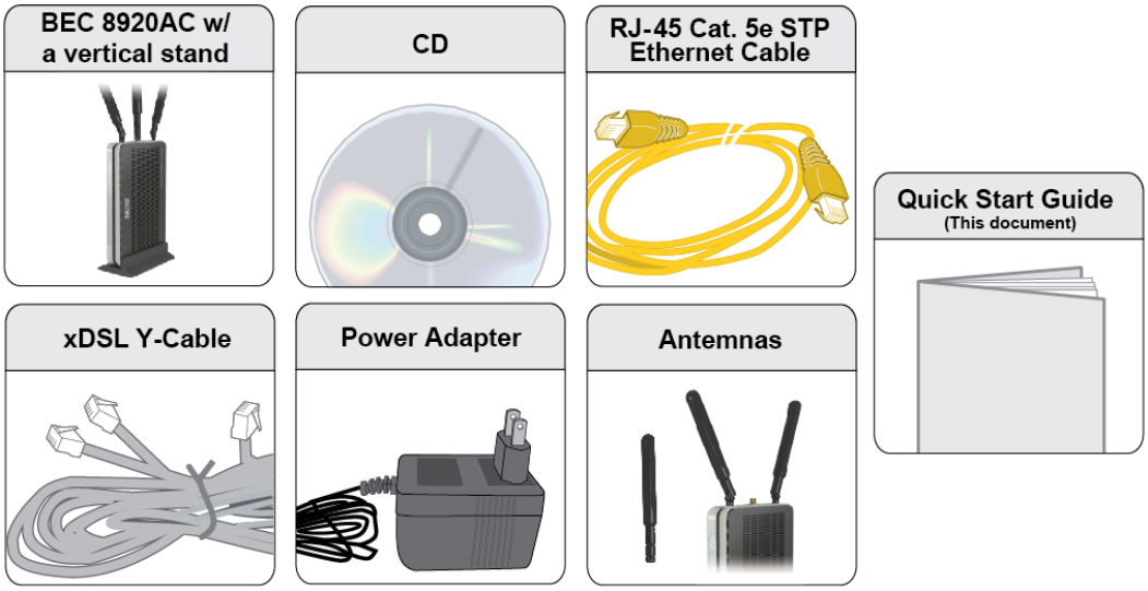
Package Contents
9 BiPAC 8920NX(L)-600 Dual Lines VDSL2/ADSL2+ Wireless 600Mbps 3G/4G LTE (VPN) Firewall Router
9 This Quick Start Guide
9 CD containing User Manual
9 RJ-45 Cat. 5e STP Ethernet Cable
9 RJ-11 xDSL/ telephone Cable
9 Vertical Stand
9 Two detachable Wi-Fi Antennas
9 Power adaptor
9 Splitter/ Micro-filter (Optional)

9
Important note for using this router
Warning
1. Do not use the router in high humidity or high temperatures.
2. Do not use the same power source for the router as other equipment.
3. Do not open or repair the case yourself. If the router is too hot, turn off the power
immediately and have it repaired at a qualified service center.
4. Avoid using this product and all accessories outdoors.
Attention
1. Place the router on a stable surface.
2. Only use the power adapter that comes with the package. Using a different voltage rating
power adapter may damage the router.

10
Device Description
The Front LEDs
LED Status Meaning
Red Boot failure or in emergency mode
Power
Green System ready
Green Connected to an Gigabit Ethernet device or to a broadband
connection device.
Orange Connect to an 10/100Mbps Ethernet device
Gigabit Ethernet Port
5/EWAN
Blinking Data being transmitted / received
Green Successfully connected to a 1000Mbos LAN device
Orange Successfully connected to a 10/100Mbos LAN device
Gigabit Ethernet Port
1-4
Blinking Data being transmitted / received
USB Green USB connection established
Green Wireless connection established
Wireless
Blinking Data being transmitted / received
Green Wireless device(s) being connected successfully via WPS
mode
Blinking WPS configuration being in progress
WPS
Off WPS is off
Green Successfully connected to an VDSL DSLAM (Line Synced)
Green Blinking VDSL synchronizing or waiting for VDSL synchronizing
Orange Successfully connected to an ADSL DSLAM (Line Synced)
Orange blinking ADSL synchronizing or waiting for VDSL synchronizing
DSL 1 /2
Off DSL cable unplugged
Green IP connected and traffic is passing through the device
Blinking Data being transmitted / received
Red BiPAC 8920NXL-600 fails to obtain and IP.
Internet
Off BiPAC 8920NXL-600 is either in bridged mode or WAN/DSL
connection is not ready

11
The Rear Ports
Port Meaning
1 ON/OFF Power ON / OFF switch.
2 PWR Connect the supplied power adapter to this jack.
3 WPS /Wireless
on/off button
By controlling the pressing time, users can achieve two different
effects:
(1) WPS: Press &hold the button for less than 6 seconds to trigger
WPS function.
(2) Wireless ON/OFF button: Press & hold the button for more than
6 seconds to On/Off the wireless.
4 Reset
Push and hold the reset button for five (5) seconds to restore to its
factory default settings (this is used when you cannot login to the
router, e.g. forgot your password)
5 E (Gb EWAN)
Connect to Fiber/ Cable/ xDSL Modem with a RJ-45 cable, for
broadband connectivity.
Note: LAN 5 automatically becomes an EWAN port when EWAN
internet interface is being selected in the GUI
6 GB LAN
Ethernet (1-5)
Connect PCs, Laptops or any other office/home LAN devices with the
supplied RJ-45 Ethernet cable (Cat-5 or Cat-5e) to any of the five
LAN ports.
Note: Port 5 is a LAN / WAN Configurable Port.
7 USB Connect with a 3G or 4G/LTE USB adaptor/dongle for mobile
connectivity.
8 DSL Connect the device to an ADSL/VDSL telephone jack or splitter using
a RJ-11 telephone cable / Y-Cable for xDSL Dual-lines
1
2
3
4
5
6
8
7
12
Cabling
One of the most common causes of problems is bad cabling or DSL line(s). Make sure that all
connected devices are turned on. On the front panel of your router is a bank of LEDs. Verify that the
LAN Link and DSL line LEDs are all lit. If they are not, verify if you are using the proper cables. If the
error persists, you may have a hardware problem. In this case, you should contact technical support.
Make sure you have a line filter with all devices (e.g. telephones, fax machines, analogue modems)
connected to the same telephone line and the wall socket (unless you are using a Central Splitter or
Central Filter installed by a qualified and licensed electrician), and ensure that all line filters are
correctly installed and the right way around. Missing line filters or line filters installed the wrong way
around can cause problems with your DSL connection, including causing frequent disconnections. If
you have a back-to-base alarm system you should contact your security provider for a technician to
make any necessary changes.

13
Chapter 3: Basic Installation
The router can be configured through your web browser. A web browser is included as a standard
application in the following operating systems: Linux, Mac OS / Windows 10/8/Vista/7/XP, etc. The
product provides an easy and user-friendly interface for configuration.
Please check your PC network components. The TCP/IP protocol stack and Ethernet network
adapter must be installed. If not, please refer to your Windows-related or other operating system
manuals.
There are ways to connect the router, either through an external repeater hub or connect directly
to your PCs. However, make sure that your PCs have an Ethernet interface installed properly prior
to connecting the router device. You ought to configure your PCs to obtain an IP address through
a DHCP server or a fixed IP address that must be in the same subnet as the router. The default IP
address of the router is 192.168.1.254 and the subnet mask is 255.255.255.0 (i.e. any attached PC
must be in the same subnet, and have an IP address in the range of 192.168.1.1 to 192.168.1.253).
The best and easiest way is to configure the PC to get an IP address automatically from the router
using DHCP. If you encounter any problem accessing the router web interface it is advisable to
uninstall your firewall program on your PCs, as they can cause problems accessing the IP address
of the router. Users should make their own decisions on what is best to protect their network.
Please follow the following steps to configure your PC network environment.
Any TCP/IP capable workstation can be used to communicate with or through this router. To
configure other types of workstations, please consult your manufacturer documentation.
14
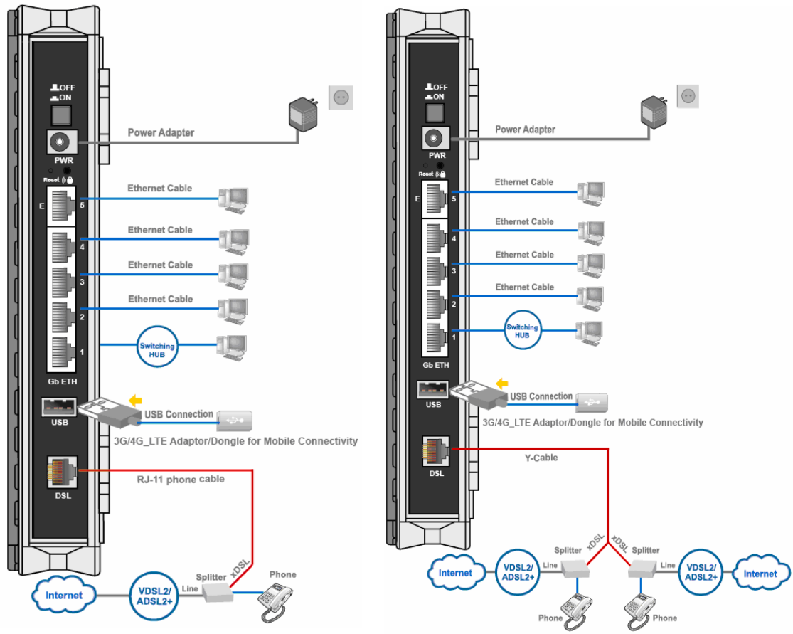
Connecting Your Router
Users can connect the ADSL2+ router as the following.
DSL Router mode:
- Single Pair- - Two Lines (bonded)
- two-paired
Broadband Router mode:
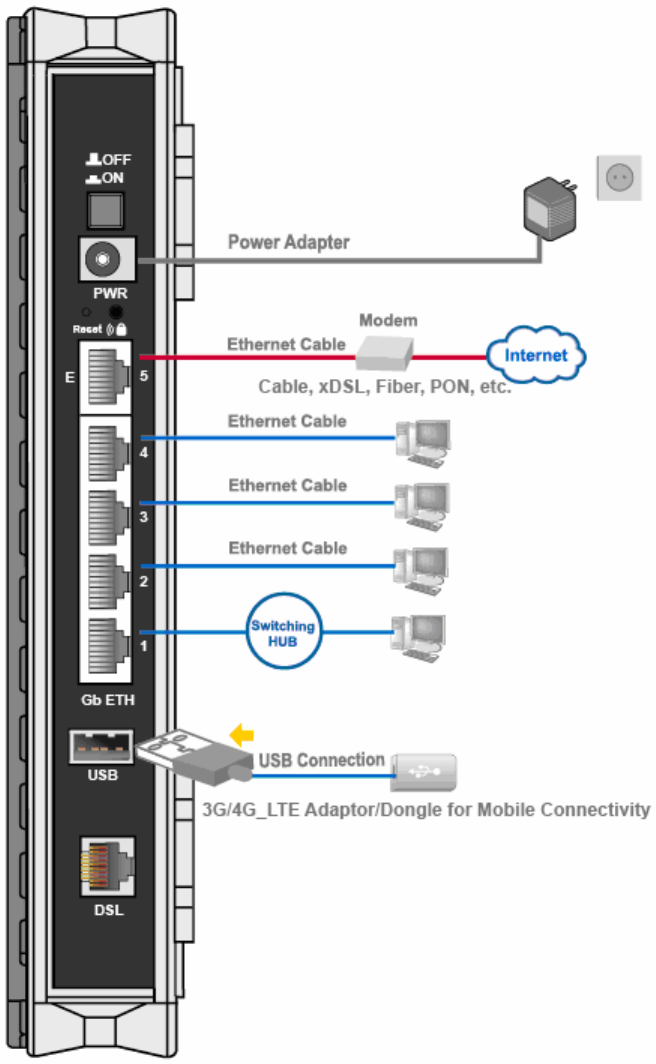
15
Broadband Connection
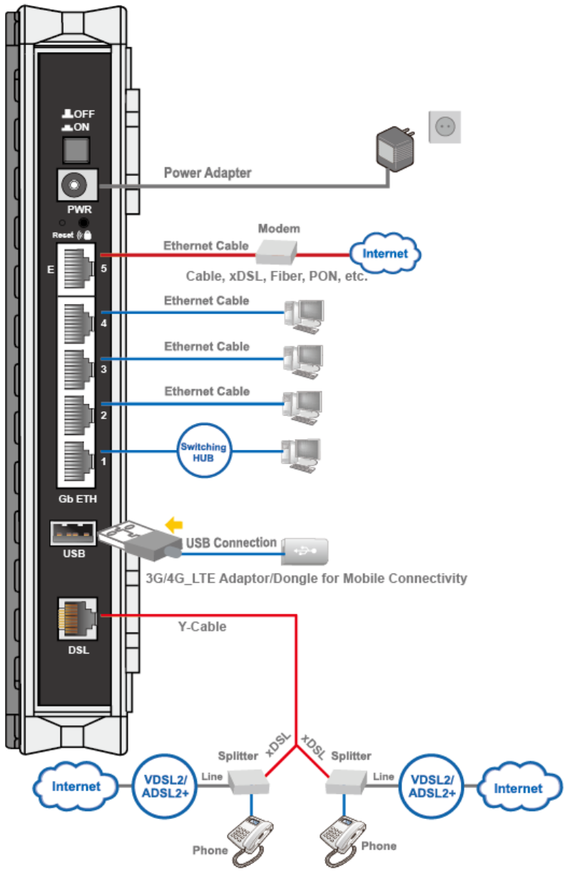
16
Automatic WAN Failover
17
Network Configuration
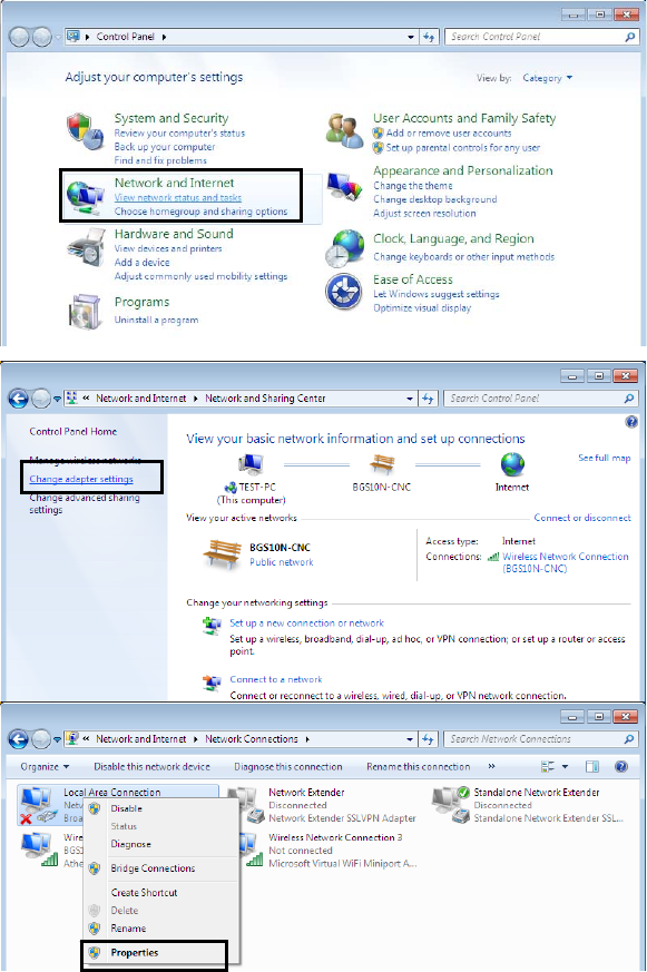
Configuring a PC in Windows 7/ 8
1. Go to Start. Click on Control
Panel.
Then click on Network and
Internet.
2. When the Network and Sharing
Center window pops up, select
and click on Change adapter
settings on the left window
panel.
3. Select the Local Area
Connection, and right click the
icon to select Properties.
18
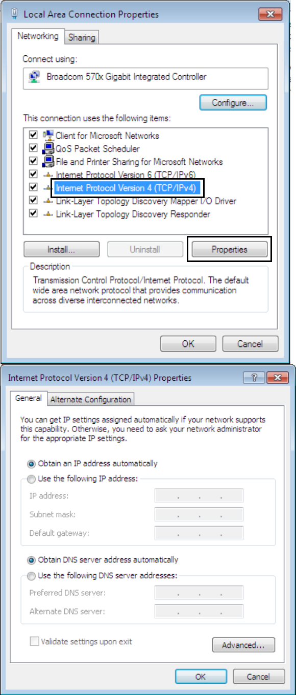
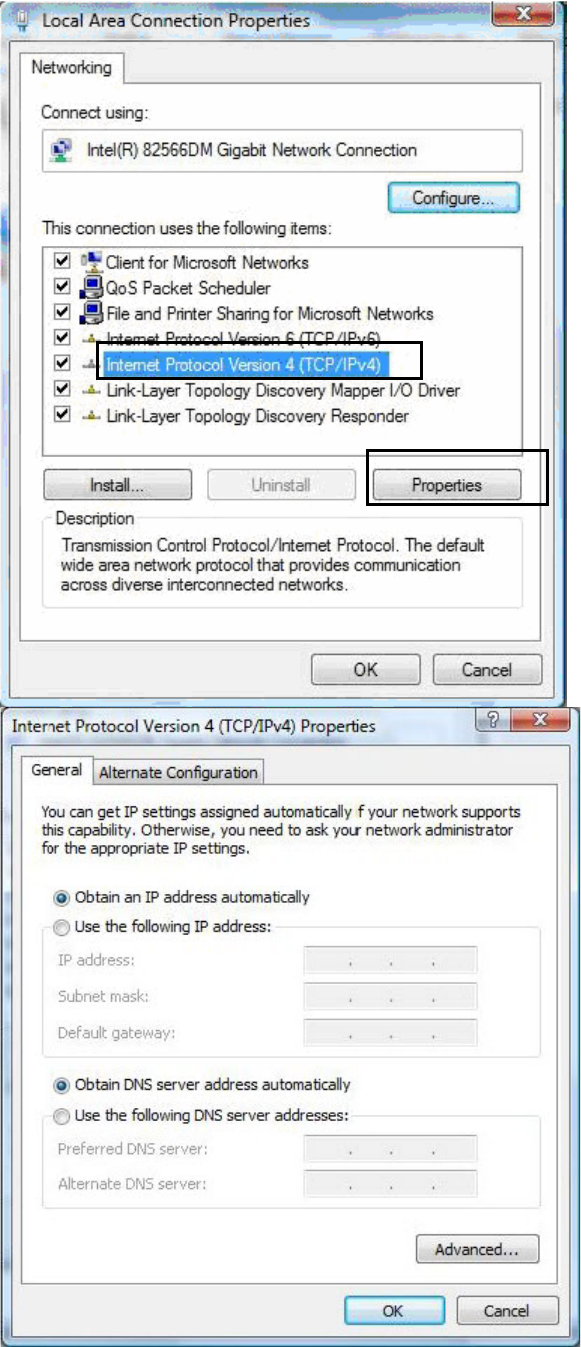
IPv4:
4. Select Internet Protocol
Version 4 (TCP/IPv4) then click
Properties
5. In the TCP/IPv4 properties
window, select the Obtain an IP
address automatically and
Obtain DNS Server address
automatically radio buttons.
Then click OK to exit the setting.
6. Click OK again in the Local
Area Connection Properties
window to apply the new
configuration.
19
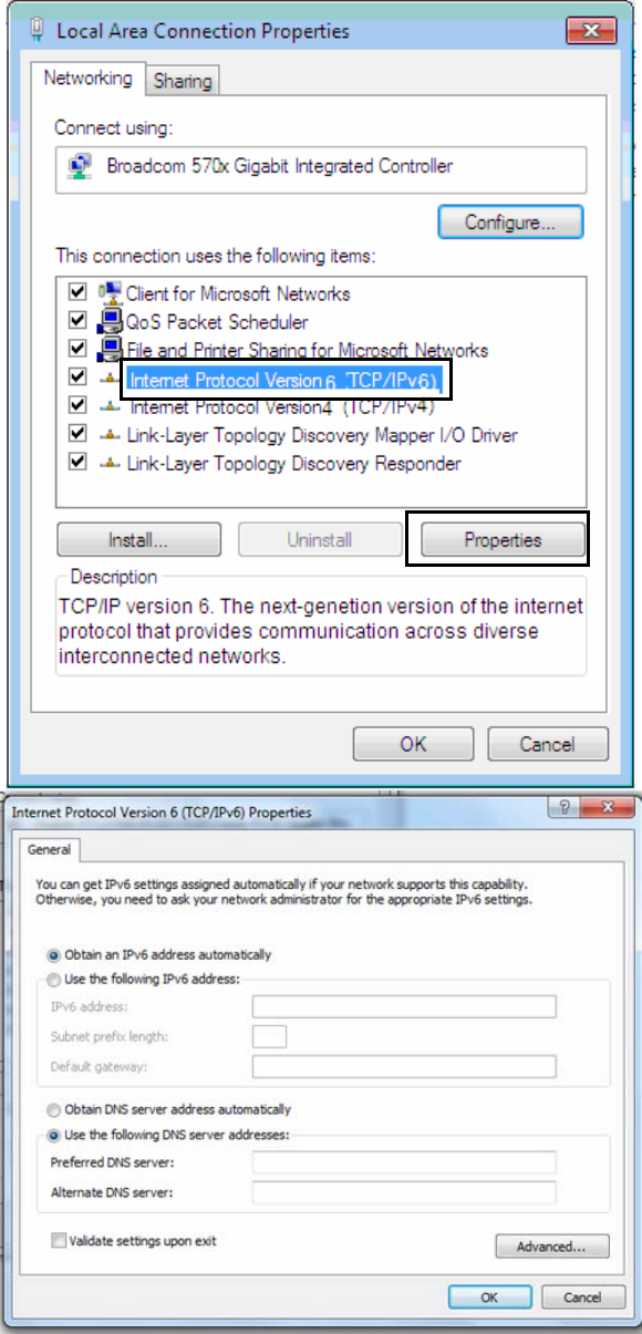
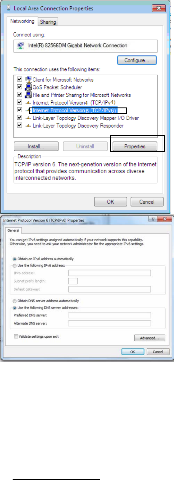
IPv6:
4. Select Internet Protocol
Version 6 (TCP/IPv6) then click
Properties
5. In the TCP/IPv6 properties
window, select the Obtain an
IPv6 address automatically
and Obtain DNS Server
address automatically radio
buttons. Then click OK to exit
the setting.
6. Click OK again in the Local
Area Connection Properties
window to apply the new
configuration.
20
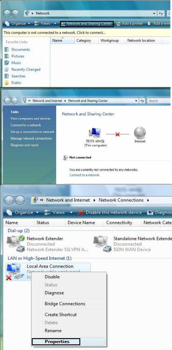
Configuring a PC in Windows Vista
1. Go to Start. Click on Network.
2. Then click on Network and
Sharing Center at the top bar.
3. When the Network and Sharing
Center window pops up, select
and click on Manage network
connections on the left window
pane.
4. Select the Local Area
Connection, and right click the
icon to select Properties.
21
IPv4:
5. Select Internet Protocol
Version 4 (TCP/IPv4) then click
Properties.
6. In the TCP/IPv4 properties
window, select the Obtain an IP
address automatically and
Obtain DNS Server address
automatically radio buttons.
Then click OK to exit the setting.
7. Click OK again in the Local Area
Connection Properties window
to apply the new configuration.
22
IPv6:
8. Select Internet Protocol
Version 6 (TCP/IPv6) then click
Properties.
9. In the TCP/IPv6 properties
window, select the Obtain an
IPv6 address automatically and
Obtain DNS Server address
automatically radio buttons.
Then click OK to exit the setting.
10. Click OK again in the Local Area
Connection Properties window
to apply the new configuration.
23
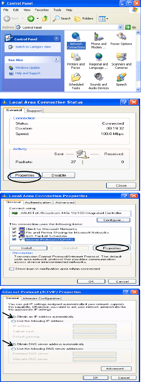
Configuring a PC in Windows XP
IPv4:
1. Go to Start / Control Panel (in Classic
View). In the Control Panel, double-click
on Network Connections
2. Double-click Local Area Connection.
3. In the Local Area Connection Status
window, click Properties.
4. Select Internet Protocol (TCP/IP) and
click Properties.
5. Select the Obtain an IP address
automatically and the Obtain DNS
server address automatically radio
buttons.
6. Click OK to finish the configuration.
24
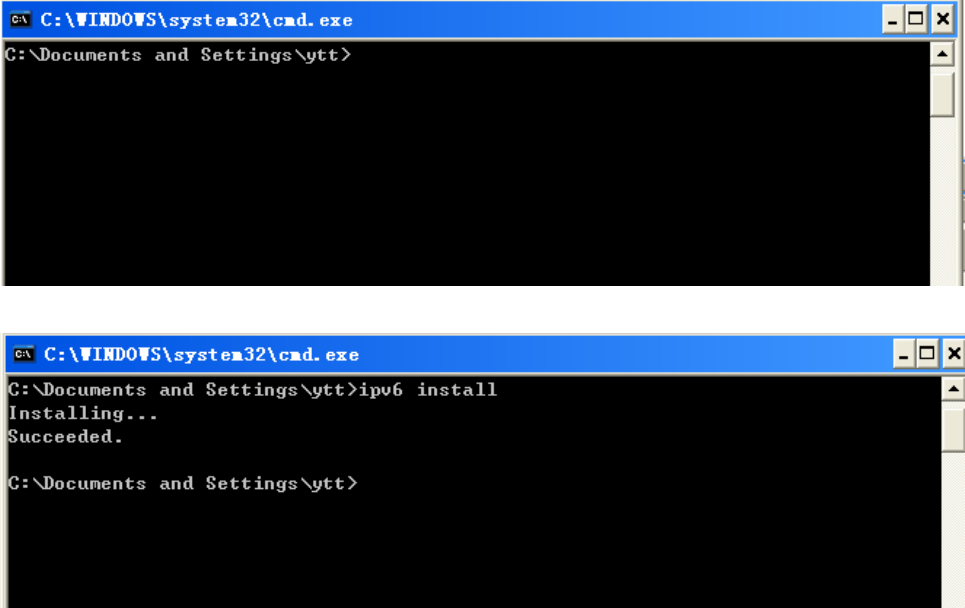
IPv6:
IPv6 is supported by Windows XP, but you should install it first.
Act as shown below:
1. On the desktop, Click Start > Run, type cmd, then press Enter key in the keyboard, the following screen
appears.
2. Key in command ipv6 install
Configuration is OK now, you can test whether it works ok.

25
Factory Default Settings
Before configuring your router, you need to know the following default settings.
Web Interface (Username and Password)
Three user levels are provided by this router, namely Administrator, Remote and Local
respectively. See Access Control .
Administrator
Username: admin
Password: admin
Local
Username: user
Password: user
Remote
Username: support
Password: support
Attention
If you have forgotten the username and/or password of the router, you can restore the device
to its default setting by pressing the Reset Button more than 5 seconds.
Device LAN IPv4 settings
IPv4 Address: 192.168.1.254
Subnet Mask: 255.255.255.0
Device LAN IPv6 settings
IPv6 Address / prefix: Default is a link-local address and is different from each other as MAC
address is different from one to one. For example: fe80:0000:0000:0000:0204:edff:fe01:0001 / 64,
the prefix initiates by fe80::
DHCP server for IPv4
DHCP server is enabled.
Start IP Address: 192.168.1.254
IP pool counts: 100

26
LAN and WAN Port Addresses
The parameters of LAN and WAN ports are pre-set in the factory. The default values are shown in
the table.
IPv4
LAN Port WAN Port
IPv4 address 192.168.1.254
Subnet Mask 255.255.255.0
DHCP server function Enabled
IP addresses for
distribution to PCs
100 IP addresses continuing
from 192.168.1.100 through
192.168.1.199
The PPPoE function is
enabled to automatically get
the WAN port configuration
from the ISP.
IPv6
LAN Port WAN Port
IPv6 address/prefix Default is a link-local address and is
different from each other as MAC
address is different from one to one.
For example :
fe80::204:edff:fe01:1/64,
the prefix initiates by fe80::
DHCP server function Enabled
The PPPoE function is
enabled to automatically get
the WAN port configuration
from the ISP.

27
Information from your ISP
Before configuring this device, you have to check with your ISP (Internet Service Provider) to find
out what kind of service is provided.
Gather the information as illustrated in the following table and keep it for reference.
PPPoE(RFC2516)
VPI/VCI, VC / LLC-based multiplexing, Username, Password, Service
Name, and Domain Name System (DNS) IP address (it can be
automatically assigned by your ISP when you connect or be set manually).
PPPoA(RFC2364)
VPI/VCI, VC / LLC-based multiplexing, Username, Password and Domain
Name System (DNS) IP address (it can be automatically assigned by your
ISP when you connect or be set manually).
DHCP Client
VPI/VCI, VC / LLC-based multiplexing, Domain Name System (DNS) IP
address (it can be automatically assigned by your ISP when you connect o
r
be set manually).
IPoA(RFC1577)
VPI/VCI, VC / LLC-based multiplexing, IP address, Subnet mask, Gateway
address, and Domain Name System (DNS) IP address (it is a fixed IP
address).
Pure Bridge
VPI/VCI, VC / LLC-based multiplexing to use Bridged Mode.
28
Easy Sign On (EZSO)
This special feature makes it easier for you to configure your router so that you can connect to the
internet in a matter of seconds without having to logon to the router GUI for any detail configuration.
This configuration method is usually auto initiated if user is to connect to the internet via Billion's
router for the first time.
After setting up the router with all the appropriate cables plugged-in, open up your IE browser, the
EZSO WEB GUI will automatically pop up and request that you enter some basic information that
you have obtained from your ISP. By following the instructions given carefully and through the
information you provide, the router will be configured in no time and you will find yourself surfing the
internet sooner than you realize.
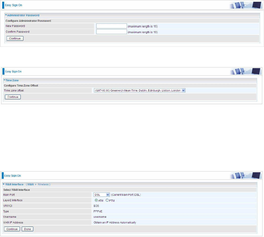
EZSO window pops up:
Step1: Set the administration password.
Step 2: Set the Time Zone.
Step 3: Configure the WAN interface.
DSL mode (ADSL mode, please choose ATM; VDSL, please choose PTM)
Here take ADSL for example.
Before configuring with DSL mode, please confirm you have correctly connected the DSL line, and it
is now synchronized.
Select DSL, press Continue to go on to next step, press “Done” to quit the setting.
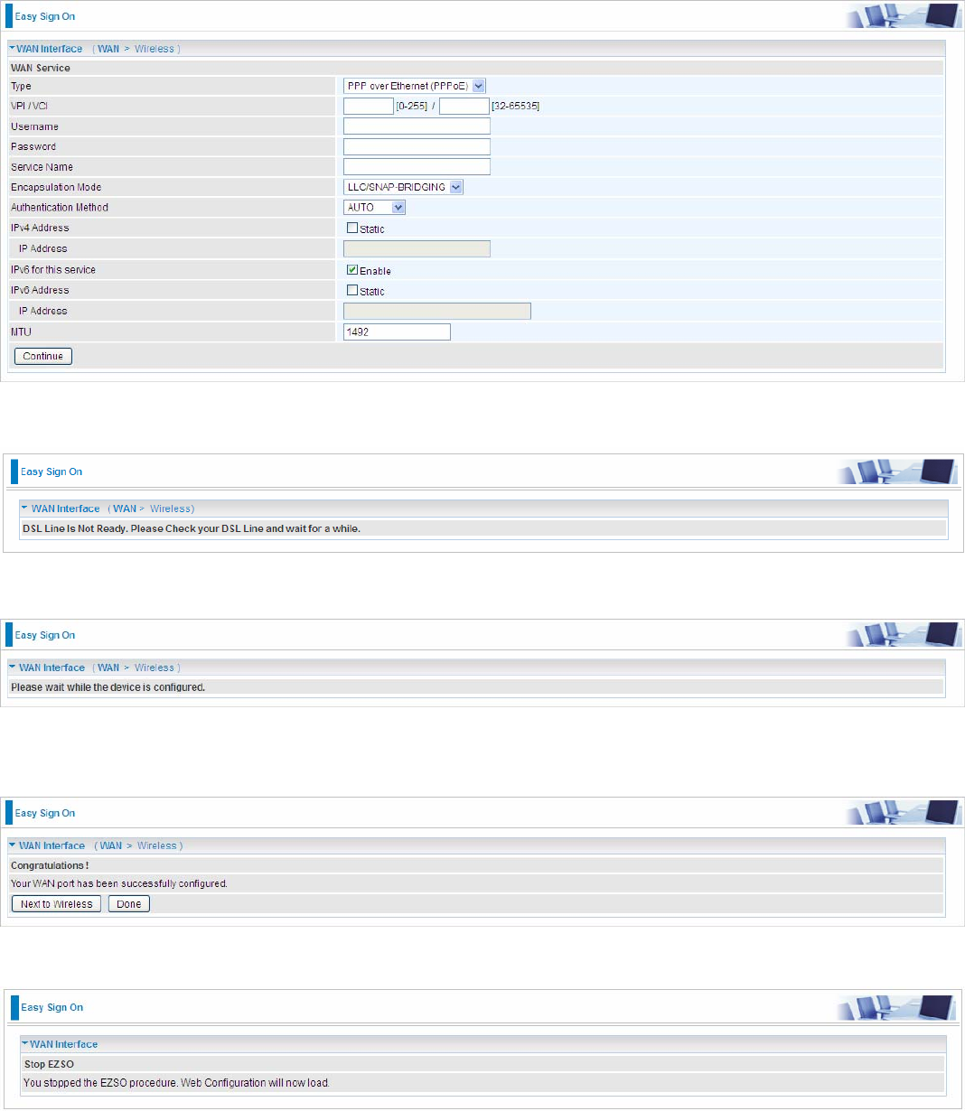
1. Enter the username, password from your ISP, for IP and DNS settings; also refer to your ISP.
29
Here IPv6 service is enabled by default.
If the DSL line doesn’t synchronize, the page will pop up warning of the DSL connection failure.
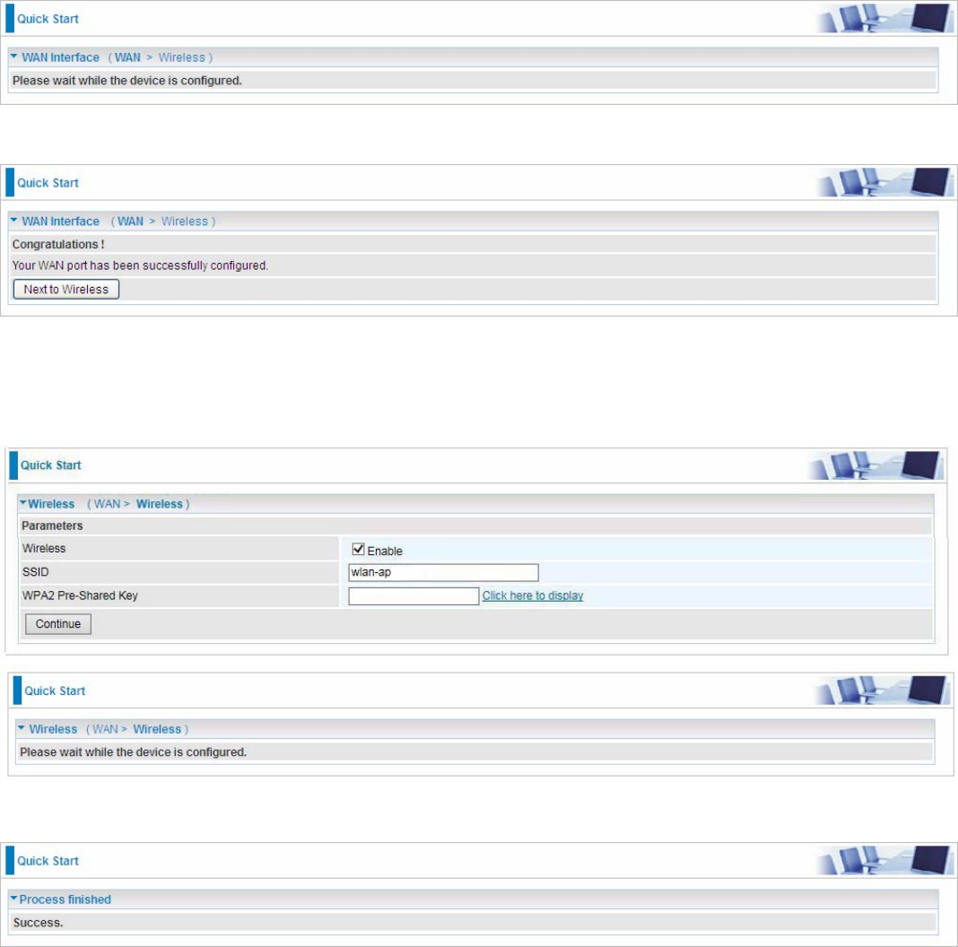
3. Wait while the device is configured (DSL synchronized).
4. WAN port configuration is success and next to wireless, if you want skip wireless setting, click
Done.
Click Done, web configuration will be loaded, you will enter the web configuration page.
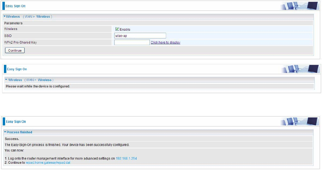
5. After the configuration is successful, click Next to Wireless button and you may proceed to
configure the Wireless setting. Enable the wireless and set the SSID and encryption Key. (1. Leave
it empty to disable the wireless security; 2. Fill in the Key, and the encryption mode will be WPA2-
PSK/AES).
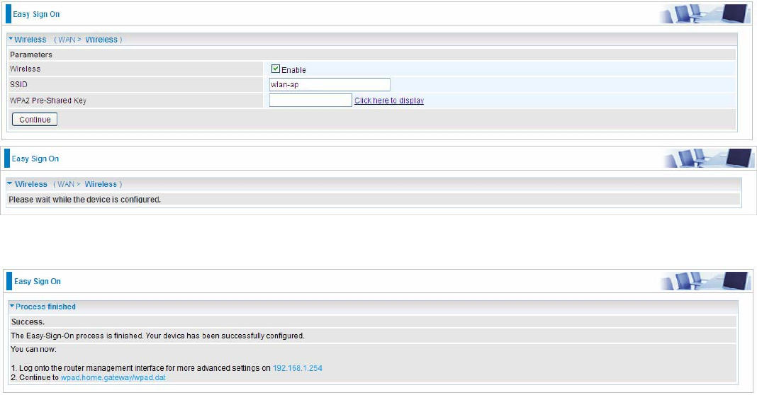
30
6. Success in configuring the EZSO.
31
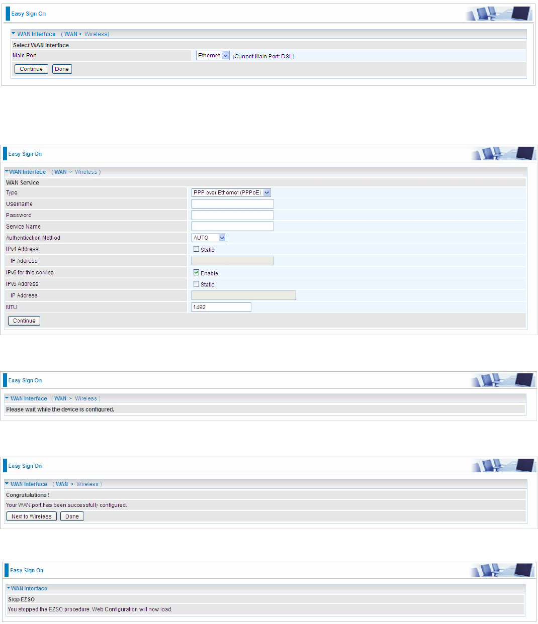
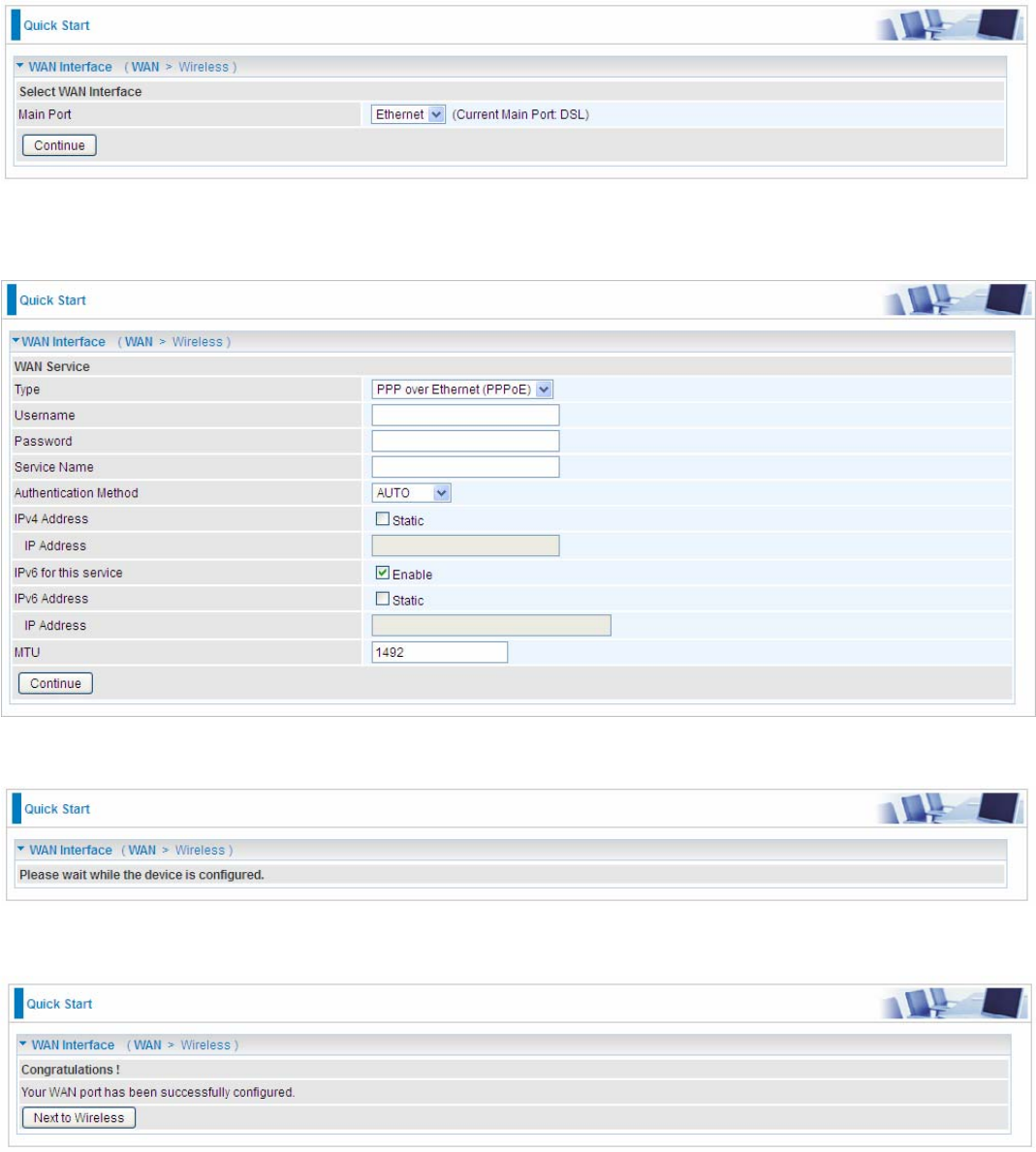
Ethernet mode
1. Select Ethernet, press Continue to go on to next step.
2. Enter the username, password from your ISP, for IP and DNS settings, also refer to your ISP.
Here IPv6 service is enabled by default.
3. Wait while the device is configured.
4. WAN port configuration is success.
Click Done, web configuration will be loaded, you will enter the web configuration page.
32
5. After the configuration is successful, click Next to Wireless button and you may proceed to
configure the Wireless setting. Enable wireless and set the SSID and encryption Key (1. Leave it
empty to disable the wireless security; 2. Fill in the Key, and the encryption mode will be WPA2-
PSK/AES).
6. Success in configuring the EZSO.
33
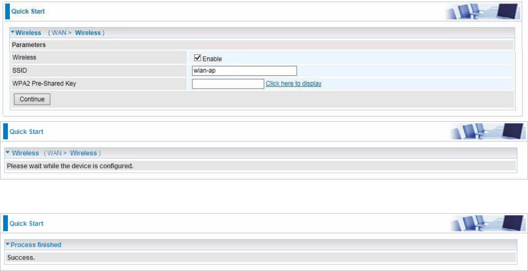
3G/4G LTE
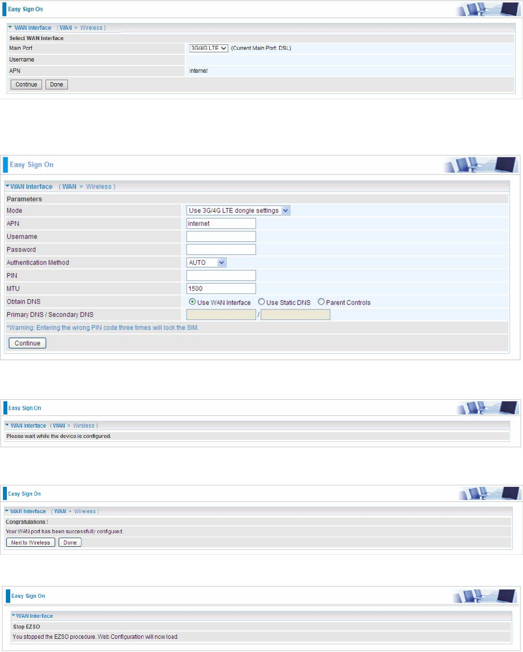
1. Select 3G/4G LTE, press Continue to go on to next step.
2. Enter the APN, username, password from your ISP, for settings about Authentication method, PIN,
etc, also refer to your ISP.
3. Wait while the device is configured.
4. WAN port configuration is success.
Click Done, web configuration will be loaded, you will enter the web configuration page.
34
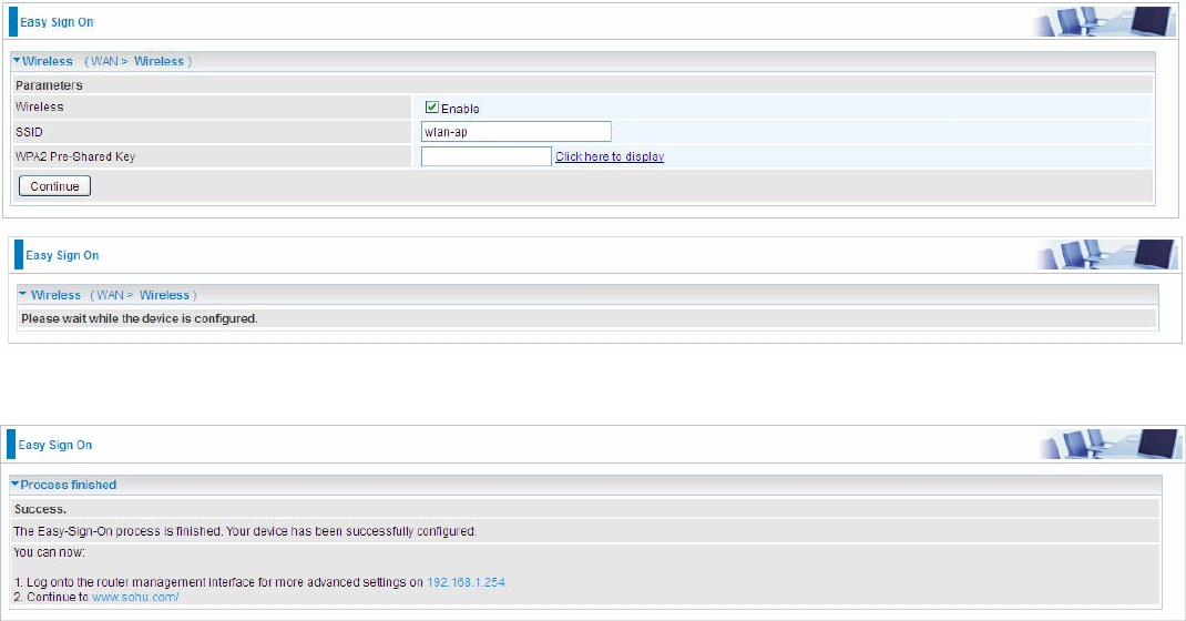
5. After the configuration is successful, click Next to Wireless button and you may proceed to
configure the Wireless setting. Enable wireless and set the SSID and encryption Key (1. Leave it
empty to disable the wireless security; 2. Fill in the Key, and the encryption mode will be WPA2-
PSK/AES).
6. Success in configuring the EZSO.
35
Chapter 4: Configuration
Configuration via Web Interface
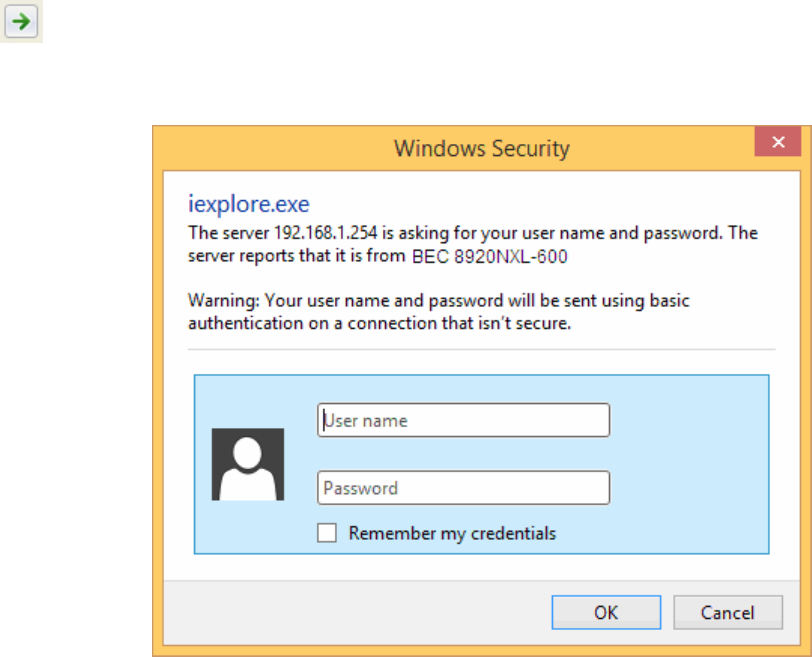
Open your web browser; enter the IP address of your router, which by default is 192.168.1.254, and
click or press ‘Enter’ key on the keyboard, a login prompt window will appear. The default root
username and password are “admin” and “admin” respectively.
Congratulations! You are now successfully logged in to the VDSL2+ Router!

36
Once you have logged on to your BiPAC 8920NXL-600 Router via your web browser, you can begin
to set it up according to your requirements. On the configuration homepage, the left navigation pane
links you directly to the setup pages, which include:
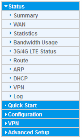
Status (Summary, WAN, Statistics, Bandwidth Usage, 3G/4G LTE Status, Route, ARP, DHCP,
Log,)
Quick Start (Quick Start)
Configuration (LAN, Wireless, WAN, System, USB, IP Tunnel, Security, Quality of Service, NAT,
Wake On LAN)
Advanced Setup (Routing, DNS, Static ARP, UPnP, Certificate, Multicast, Management,
Diagnostics)
37
Status
This Section gives users an easy access to the information about the working router and access to
view the current status of the router. Here Summary, WAN, Statistics, Bandwidth Usage, 3G/4G
LTE Status, Route, ARP, DHCP , and Log subsections are included.
38
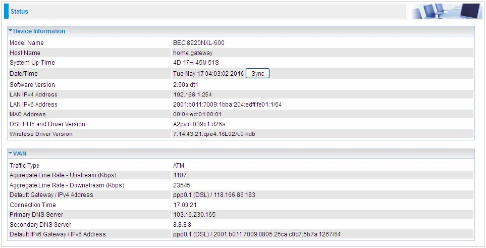
Summary
The basic information about the device is provided here (the following is a configured
screenshots to let users understand clearly).
Device Information
Model Name: Displays the model name.
Host Name: Displays the name of the router.
System Up-Time: Displays the elapsed time since the device is on.
Date/Time: Displays the current exact date and time. Sync button is to synchronize the
Date/Time with your PC time without regard to connecting to internet or not.
Software Version: Firmware version.
LAN IPv4 Address: Displays the LAN IPv4 address.
LAN IPv6 Address: Displays the LAN IPv6 address. Default is a Link-Local address, but
when connects to ISP, it will display the Global Address, like above figure.
MAC Address: Displays the MAC address.
DSL PHY and Driver Version: Display DSL PHY and Driver version.
Wireless Driver Version: Displays wireless driver version.
WAN
Line Rate – Upstream (Kbps): Displays Upstream line Rate in Kbps.
Line Rate – Downstream (Kbps): Displays Downstream line Rate in Kbps.
Default Gateway/IPv4 Address: Display Default Gateway and the IPv4 address.
Connection Time: Displays the elapsed time since ADSL connection is up.
Primary DNS Server: Displays IPV4 address of Primary DNS Server.
Secondary DNS Server: Displays IPV4 address of Secondary DNS Server.
Default IPv6 Gateway/IPv6 Address: Display the IPv6 Gateway and the obtained IPv6
address.
39
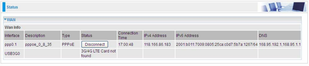
WAN
This table displays the information of the WAN connections, users can turn here for WAN connection
information.
Interface: The WAN connection interface.
Description: The description of this connection.
Type: The protocol used by this connection.
Status: To disconnect or connect the link.
Connection Time: The WAN connection time since WAN is up.
IPv4 Address: The WAN IPv4 Address the device obtained.
IPv6 Address: The WAN IPv6 Address the device obtained.
DNS: The DNS address the device obtained.
40
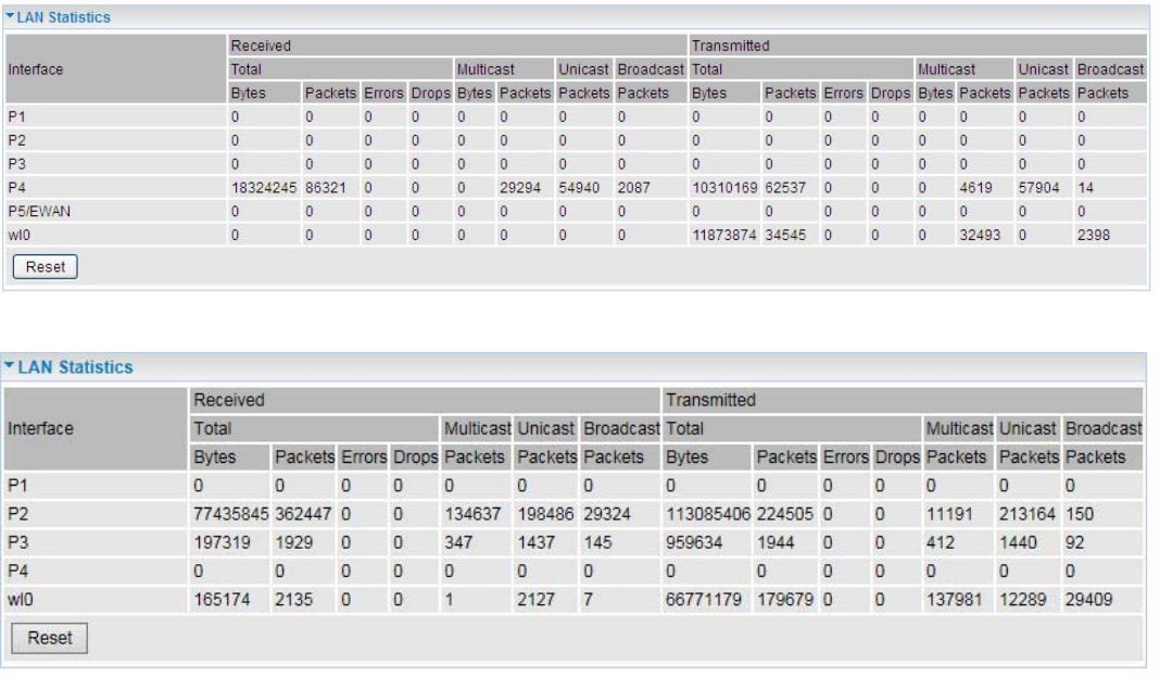
Statistics
LAN
The table shows the statistics of LAN.
Note: P5 can be configured as EWAN, and when the device is in EWAN profile, there is no
P5/EWAN interface as P5 is working as a WAN port.
(DSL)
(EWAN)
Interface: List each LAN interface. P1-P5 indicates the LAN interfaces (P5 can be configured as
EWAN).
Bytes: Display the total Received and Transmitted traffic statistics in Bytes for each interface.
Packets: Display the total Received and Transmitted traffic statistics in Packets for each interface.
Errors: Display the total statistics of errors arising in Receiving or Transmitting data for each
interface.
Drops: Display the total statistics of drops arising in Receiving or Transmitting data for each
interface.
Multicast (packets): Display the Received and Transmitted multicast Packets for each interface.
Unicast (packets): Display the Received and Transmitted unicast Packets for each interface.
Broadcast (packets): Display the Received and Transmitted broadcast Packets for each interface.
Reset: Press this button to refresh the statistics.
41
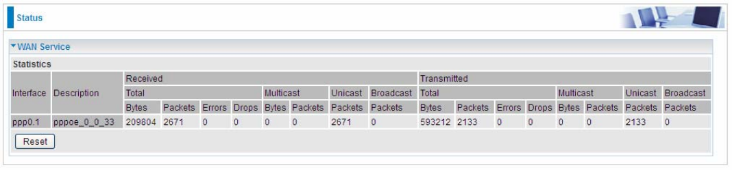
WAN Service
The table shows the statistics of WAN.
Interface: Display the connection interface.
Description: The description for the connection.
Bytes: Display the Received and Transmitted traffic statistics in Bytes for every WAN interface.
Packets: Display the Received and Transmitted traffic statistics in Packests for every WAN interface.
Errors: Display the statistics of errors arising in Receiving or Transmitting data for every WAN
interface.
Drops: Display the statistics of drops arising in Receiving or Transmitting data for every WAN
interface.
Multicast (packets): Display the Received and Transmitted multicast Packets for every WAN
interface.
Unicast (packets): Display the Received and Transmitted unicast Packets for every WAN interface.
Broadcast (packets): Display the Received and Transmitted broadcast Packets for every WAN
interface.
Reset: Press this button to refresh the statistics.
42
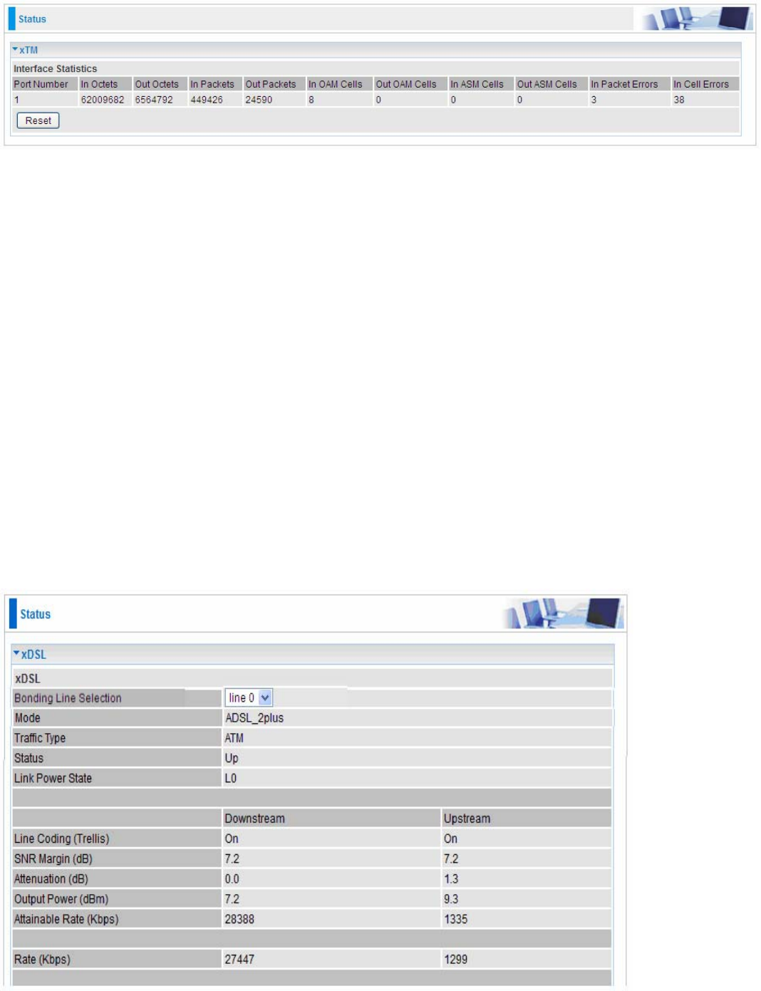
xTM
The Statistics-xTM screen displays all the xTM statistics
Port Number: Shows number of the port for xTM.
In Octets: Number of received octets over the interface.
Out Octets: Number of transmitted octets over the interface.
In Packets: Number of received packets over the interface.
Out Packets: Number of transmitted packets over the interface.
In OAM Cells: Number of OAM cells received.
Out OAM Cells: Number of OAM cells transmitted.
In ASM Cells: Number of ASM cells received.
Out ASM Cells: Number of ASM cells transmitted.
In Packet Errors: Number of received packets with errors.
In Cell Errors: Number of received cells with errors.
Reset: Click to reset the statistics.
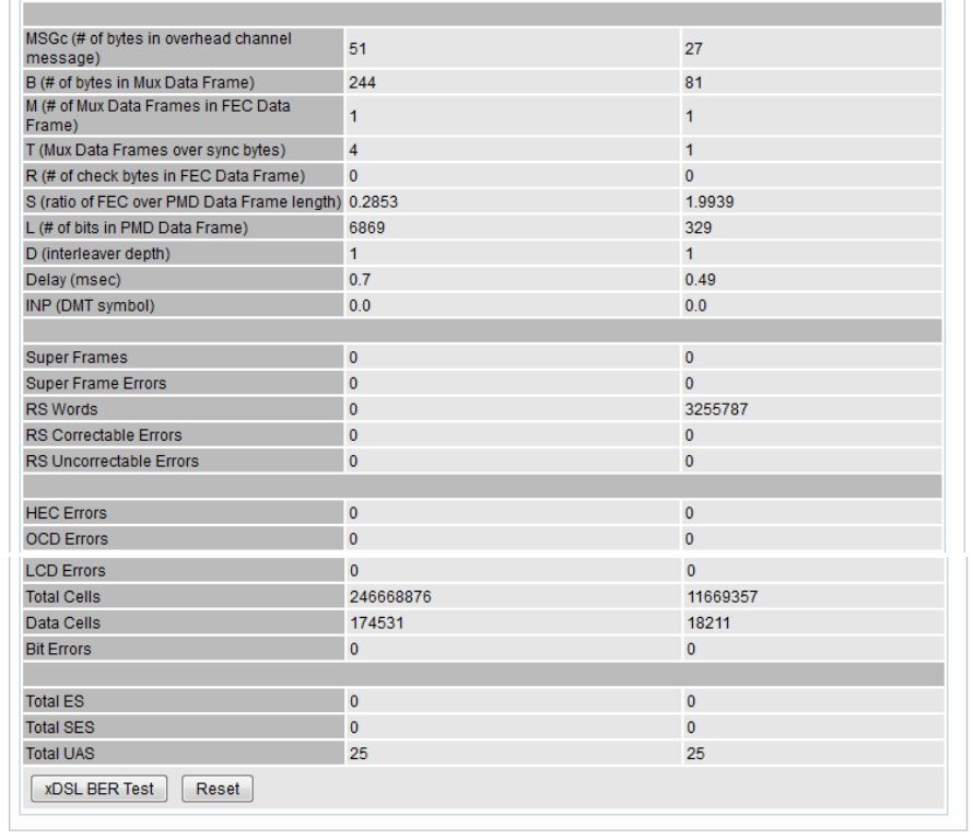
xDSL
43
Mode: Modulation protocol, including G.dmt, G.lite, T1.413, ADSL2, AnnexL, ADSL2+ and AnnexM.
Traffic Type: Transfer mode, here supports ATM and PTM.
Status: Show the status of DSL link.
Link Power State: Show link output power state.
Line Coding (Trellis): Trellis on/off.
SNR Margin (dB): Show the Signal to Noise Ratio(SNR) margin.
Attenuation (dB): This is estimate of average loop attenuation of signal.
Output Power (dBm): Show the output power.
Attainable Rate (Kbps): The sync rate you would obtain.
Rate (Kbps): Show the downstream and upstream rate in Kbps.
MSGc (#of bytes in overhead channel message): The number of bytes in overhead channel
message.
B (# of bytes in Mux Data Frame): The number of bytes in Mux Data frame.
M (# of Mux Data Frames in FEC Data Frame): The number of Mux Data frames in FEC frame.
T (Mux Data Frames over sync bytes): The number of Mux Data frames over all the sync bytes.
R (# of check bytes in FEC Data Frame): The number of check bytes in FEC frame.
S (ratio of FEC over PMD Data Frame length): The ratio of FEC over PMD Data frame length
L (# of bits in PMD Data Frame): The number of bit in PMD Data frame
D (interleaver depth): Show the interleaver depth.
Delay (msec): Show the delay time in msec.
44
INP (DMT symbol): Show the DMT symbol.
Super Frames: The total number of super frames.
Super Frame Errors: the total number of super frame errors.
RS Words: Total number of Reed-Solomon code errors.
RS Correctable Errors: Total number of RS with correctable errors.
RS Uncorrectable Errors: Total number of RS words with uncorrectable errors.
HEC Errors: Total number of Header Error Checksum errors.
OCD Errors: Total number of out-of-cell Delineation errors.
LCD Errors: Total number of Loss of Cell Delineation.
Total Cells: Total number of cells.
Data Cells: Total number of data cells.
Bit Errors: Total number of bit errors.
Total ES: Total Number of Errored Seconds.
Total SES: Total Number of Severely Errored Seconds.
Total UAS: Total Number of Unavailable Seconds.
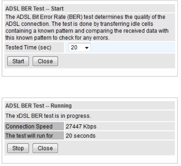
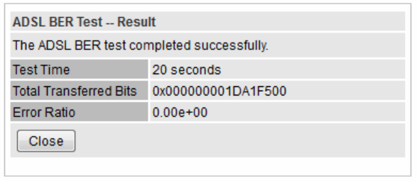
xDSL BER Test: Click this button to start a bit Error Rate Test. The ADSL Bit Error Rate (BER) test
determines the quality of the ADSL connection. The test is done by transferring idle cells containing
a known pattern and comparing the received data with this known pattern to check for any errors.
Select the Tested Time(sec), press Start to start test.
When it is OK, the following test result window will appear. You can view the quality of ADSL
connection. Here the connection is OK.
45
Reset: Click this button to reset the statistics.
46
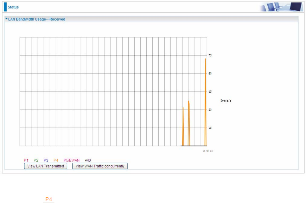
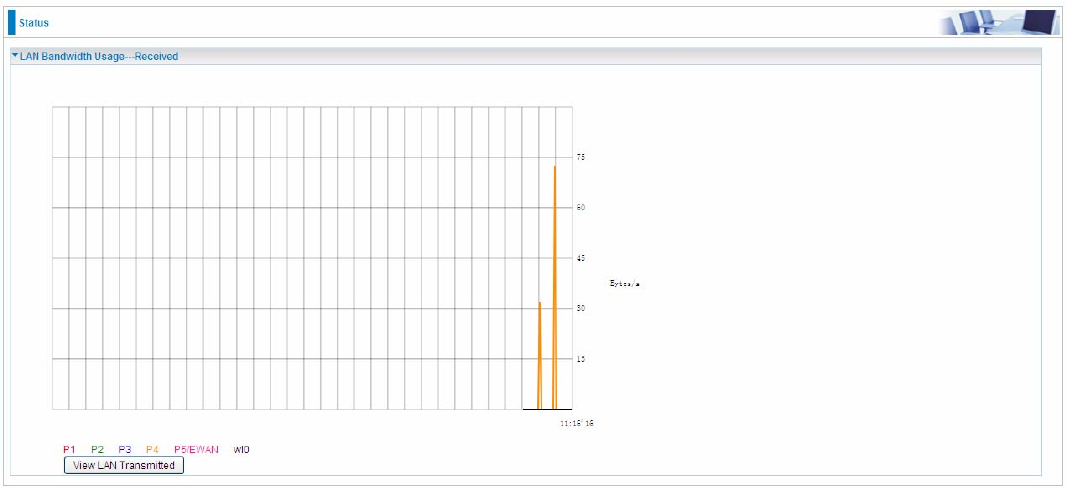
Bandwidth Usage
Bandwidth Usage provides users direct view of bandwidth usage with simple diagram. Bandwidth
usage shows the use of the bandwidth from two angles: Transmitted and Received, giving users a
clear idea of the usage.
LAN
Note: P5 can be configured as EWAN, and when the device is in EWAN profile, there is no
P5/EWAN interface as P5 is working as a WAN port.
Press View LAN Transmitted button to change the diagram to the statistics of the LAN Transmitted
Bytes. (Note: means Ethernet port #4, and the traffic information of the port #4 is identified with
orange, the same color with P4 in the diagram; other ports all take the same mechanism.)
47
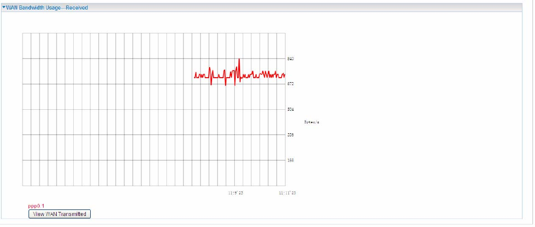
When you press View WAN Traffic concurrently button, the WAN Bandwidth Usage pops up so
that users can view the WAN traffic concurrently.
48
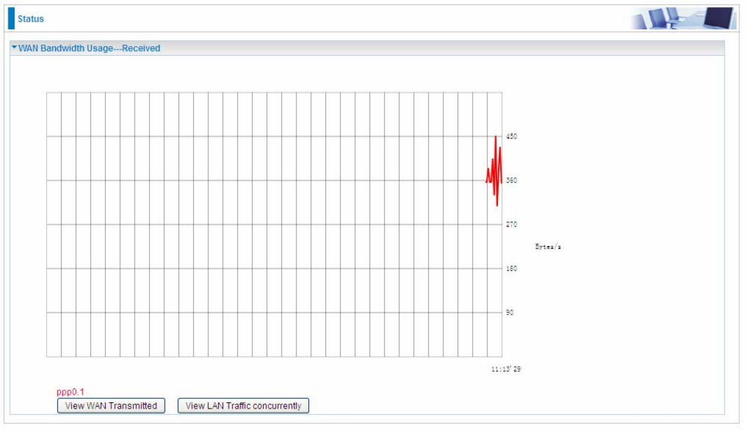
WAN Service
Press View WAN Transmitted button to change the diagram to the statistics of the WAN
Transmitted Bytes.
49
Press View LAN Traffic concurrently button to directly switch to the LAN Bandwidth Usage page
to view the LAN traffic concurrently.
50
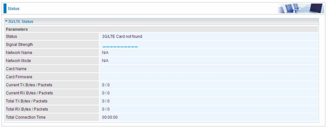
3G/4G LTE Status
Status: The current status of the 3G/4G LTE connection.
Signal Strength: The signal strength bar and dBm value indicates the current 3G/4G-LTE signal
strength. The front panel 3G/4G LTE Signal Strength LED indicates the signal strength as well.
Network Name: The name of the 3G/4G LTE network the router is connecting to.
Network Mode: The current operation mode for 3G/4G LTE module, it depends on service provider
and card’s limitation, GSM or UMTS.
Card Name: Given a name for the embedded 3G/4G LTE module.
Card Firmware: Current used FW in the 3G/4G LTE module.
Current Received (RX) /Transmitted (TX) Bytes: Current Rx/TX (receive/transmit) packets in Byte
Total Received (RX) /Transmitted (TX) Bytes: The total Rx/TX (receive/transmit) packets in Byte
Total Connection Time: The total of 3G/4G LTE dongle connection time since the 3G/4G LTE is up
and running
51
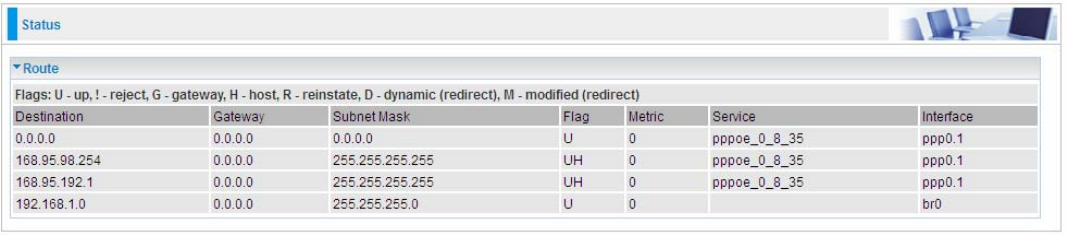
Route
Destination: The IP address of destination network.
Gateway: The IP address of the gateway this route uses.
Subnet Mask: The destination subnet mask.
Flag: Show the status of the route.
L U: Show the route is activated or enabled.
L H (host): destination is host not the subnet.
L G: Show that the outside gateway is needed to forward packets in this route.
L R: Show that the route is reinstated from dynamic routing.
L D: Show that the route is dynamically installed by daemon or redirecting.
L M: Show the route is modified from routing daemon or redirect.
Metric: Display the number of hops counted as the Metric of the route.
Service: Display the service that this route uses.
Interface: Display the existing interface this route uses.
52
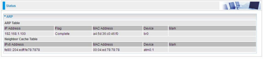
ARP
This section displays the router’s ARP (Address Resolution Protocol) Table, which shows the
mapping of Internet (IP) addresses to Ethernet (MAC) addresses. This is useful as a quick way of
determining the MAC address of the network interface of your PCs to use with the router’s Security
– MAC Filtering function. Here IPv6 Neighbor Table, listed with IPv6 address-MAC mapping, is
supported.
ARP table
IP Address: Shows the IP Address of the device that the MAC address maps to.
Flag: Shows the current status of the ARP entries.
L Complete: the route resolving is processing well.
L M(Marked as permanent entry): the route is permanent.
L P (publish entry): publish this route item.
MAC Address: Shows the MAC address that is corresponded to the IP address of the device it is
mapped to.
Device: here refers to the physical interface, it is a concept to identify Clients from LAN or WAN. For
example, the Clients in LAN, here displays “br0”.
Mark: Show clearly the SSID (WLAN) the device is in.
Neighbor Cache Table
IPv6 address: Shows the IPv6 Address of the device that the MAC address maps to.
MAC Address: Shows the MAC address that is corresponded to the IPv6 address of the device it is
mapped to.
Device: here refers to the physical interface, it is a concept to identify Clients from LAN or WAN. For
example, the Clients in LAN, here displays “br0”.
Mark: Show clearly the SSID (WLAN) the device is in.
53
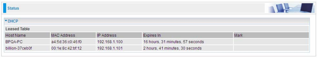
DHCP
The DHCP Table lists the DHCP lease information for all IP addresses assigned by the DHCP server
in the device.
Host Name: The Host Name of DHCP client.
MAC Address: The MAC Address of internal DHCP client host.
IP Address: The IP address which is assigned to the host with this MAC address.
Expires in: Show the remaining time after registration.
Mark: Show clearly the SSID (WLAN) the device is in.
54
VPN (BiPAC 8920NX-600 only)
VPN status viewing section provides users IPSec, PPTP, L2TP, and GRE VPN status.
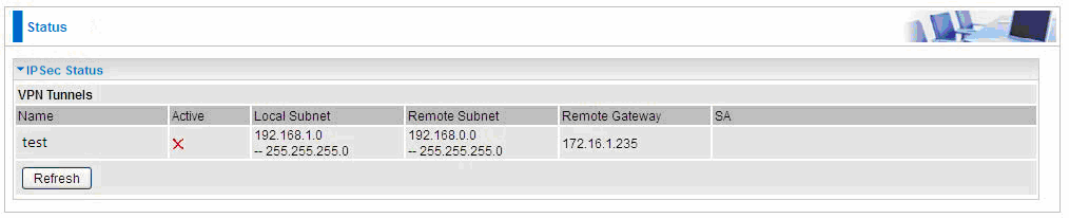
IPSec
Name: The IPSec connection name.
Active: Display the connection status.
Local Subnet: Display the local network.
Remote Subnet: Display the remote network.
Remote Gateway: The remote gateway address.
SA: The Security Association for this IPSec entry.
Refresh: Click this button to refresh the tunnel status.
55
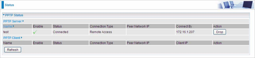
PPTP
PPTP Server
Name: The PPTP connection name.
Enable: Display the connection status with icons.
Status: The connection status.
Connection Type: Remote Access or LAN to LAN.
Peer Network IP: Display the remote network and subnet mask in LAN to LAN PPTP connection.
Connected By: Display the IP of remote connected client.
Action: Act to the connection. Click Drop button to disconnect the tunnel connection.
PPTP Client
Name: The PPTP connection name.
Enable: Display the connection status with icons.
Status: The connection status.
Connection Type: Remote Access or LAN to LAN.
Peer Network IP: Display the remote network and subnet mask in LAN to LAN PPTP connection.
Client: Assigned IP by PPTP server.
Action: Act to the connection. Click Drop button to disconnect the tunnel connection.
Refresh: Click this button to refresh the connection status.
56
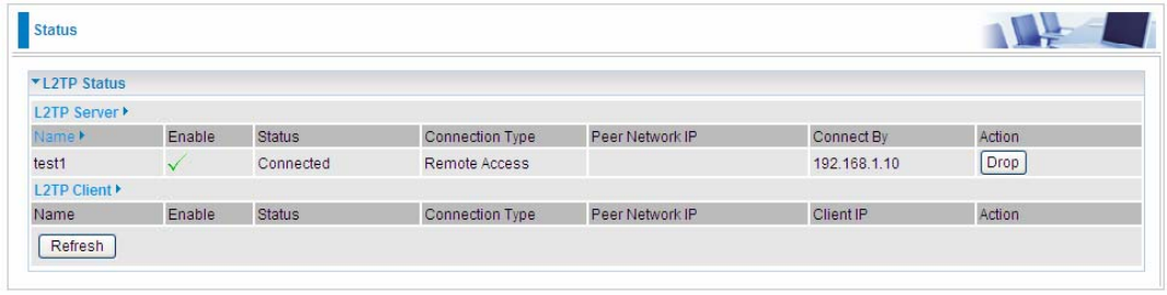
L2TP
L2TP Server
Name: The L2TP connection name.
Enable: Display the connection status with icons.
Status: The connection status.
Connection Type: Remote Access or LAN to LAN.
Peer Network IP: Display the remote network and subnet mask in LAN to LAN L2TP connection.
Connected By: Display the IP of remote connected client.
Action: Act to the connection. Click Drop button to disconnect the tunnel connection.
L2TP Client
Name: The L2TP connection name.
Enable: Display the connection status with icons.
Status: The connection status.
Connection Type: Remote Access or LAN to LAN.
Peer Network IP: Display the remote network and subnet mask in LAN to LAN L2TP connection.
Client: Assigned IP by L2TP server.
Action: Act to the connection. Click Drop button to disconnect the tunnel connection.
Refresh: Click this button to refresh the connection status.
57
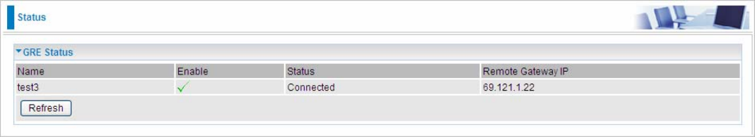
GRE
Name: The GRE connection name.
Enable: Display the connection status with icons.
Status: The connection status, connected or disable.
Remote Gateway: The IP of remote gateway.
Refresh: Click this button to refresh the connection status.
58
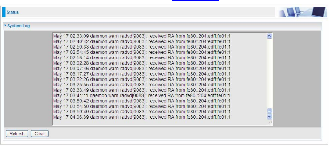
Log
System Log
Display system logs accumulated up to the present time. You can trace historical information with
this function. And the log policy can be configured in Configure Log section.
Refresh: Click to update the system log.
Clear: Click to clear the current log from the screen.
59
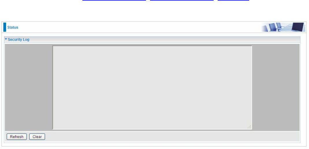
Security Log
Security log displays the message logged about security, like filter messages and some firewall
message. You can turn to IP Filtering Outgoing, IP Filtering Incoming, URL Filter to determine if you
want to log this information. Also you can turn to Configure Log section below to determine the level
to log the message. You can use this to track potential threats to your system and network.
Refresh: Click to update the security log.
Clear: Click to clear the current log from the screen.
60
Quick Start
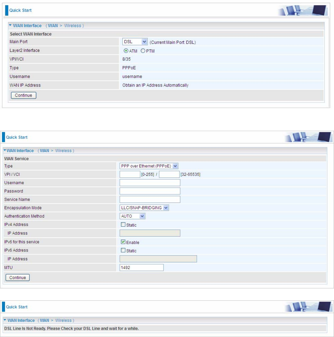
Quick Start
This part allows you to quickly configure and connect your router to internet.
DSL mode (ADSL mode, please choose ATM; VDSL, please choose PTM)
Here take ADSL for example.
Select DSL, press Continue to go on to next step. Enter the username, password from your ISP, for
IP and DNS settings; also refer to your ISP. Here IPv6 service is enabled by default.
If the DSL line is not synchronized, the page will pop up warning of the DSL connection failure.
61
3. Wait while the device is configured.
4. WAN port configuration is successful.
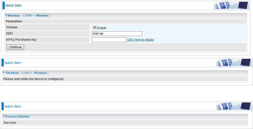
5. After the configuration is successful, click Next to Wireless button and you may proceed to
configure the Wireless setting. Enable the wireless and set the SSID and encryption Key (1. Leave it
empty to disable the wireless security; 2. Fill in the Key, and the encryption mode will be WPA2-
PSK/AES).
6. Success.
Go back to Status > Summary for more information.
62
Ethernet mode
1. Select Ethernet, press Continue to go on to next step.
2. Enter the username, password from your ISP, for IP and DNS settings; also refer to your ISP.
Here IPv6 service is enabled by default.
3. Wait while the device is configured.
4. WAN port configuration is successful.
63
5. After the configuration is successful, click Next to Wireless button and you may proceed to
configure the Wireless setting. Enable the wireless and set the SSID and encryption Key (1. Leave it
empty to disable the wireless security; 2. Fill in the Key, and the encryption mode will be WPA2-
PSK/AES). For detail setting, please go to the Wireless part in this Manual.
6. Success.
Go back to Status > Summary for more information
64
3G/4G LTE
1. Select 3G/4G LTE, press Continue to go on to next step.
2. Select the 3G mode, and enter the APN, username, password from your ISP; and check with your
ISP with the authentication method setting.
3. Wait while the device is configured.
4. WAN port configuration is successful.
65
5. After the configuration is successful, click Next to Wireless button and you may proceed to
configure the Wireless setting. Enable the wireless and set the SSID and encryption Key (1. Leave it
empty to disable the wireless security; 2. Fill in the Key, and the encryption mode will be WPA2-
PSK/AES). For detail setting, please go to the Wireless part in this Manual.
6. Success.
Go back to Status > Summary for more information.
66
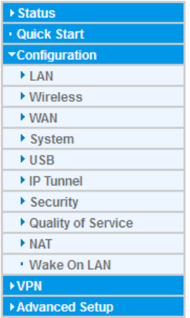
Configuration
When you click this item, the column will expand to display the sub-items that will allow you to further
configure your router.
LAN, Wireless, WAN, System, USB, IP Tunnel, Security, Quality of Service, NAT and Wake On
LAN.
The function of each configuration sub-item is described in the following sections.
67
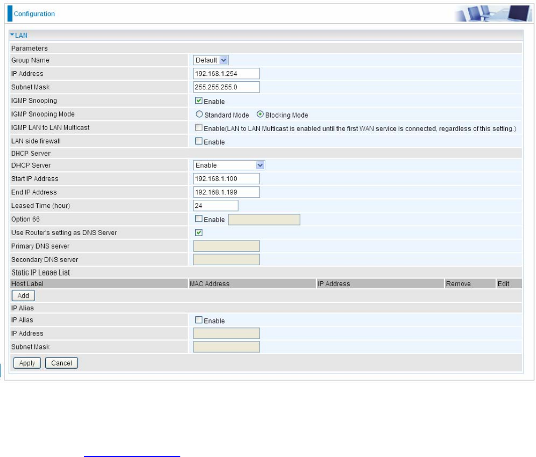
LAN - Local Area Network
A Local Area Network (LAN) is a shared communication system network where many computers
are connected. This type of network is area defined and is usually limited to a confined region within
a building.
Ethernet
Parameters
Group Name: This refers to the group you set in Interface Grouping section; you can set the
parameters for the specific group. Select the group via the drop-down box. For more information
please refer to Interface Grouping of this manual.
IP address: the IP address of the router. Default is 192.168.1.254.
Subnet Mask: the default Subnet mask on the router.
IGMP Snooping: Enable or disable the IGMP Snooping function. Without IGMP snooping,
multicast traffic is treated in the same manner as broadcast traffic - that is, it is forwarded to all
ports. With IGMP snooping, multicast traffic of a group is only forwarded to ports that have
members of that group.”
When enabled, you will see two modes:
L Standard Mode: In standard mode, multicast traffic will flood to all bridge ports when no
client subscribes to a multicast group.
L Blocking Mode: In blocking mode, the multicast data will be blocked when there are no
client subscribes to a multicast group, it won’t flood to the bridge ports.
68
IGMP LAN to LAN Multicast: Check to determine whether to support LAN to LAN (Intra LAN)
Multicast. If user want to have a multicast data source on LAN side and he wants to get IGMP
snooping enabled, then this LAN-to-LAN multicast feature should be enabled.
LAN side firewall: Enable to drop all traffic from the specified LAN group interface. After activating it,
all incoming packets by default will be dropped, and the user on the specified LAN group interface
can't access CPE anymore. But, you can still access the internet service. If user wants to manage
the CPE, please turn to IP Filtering Incoming to add the allowing rules. Note that all incoming
packets by default will be dropped if the LAN side firewall is enabled and user cannot manage this
CPE from the specified LAN group.
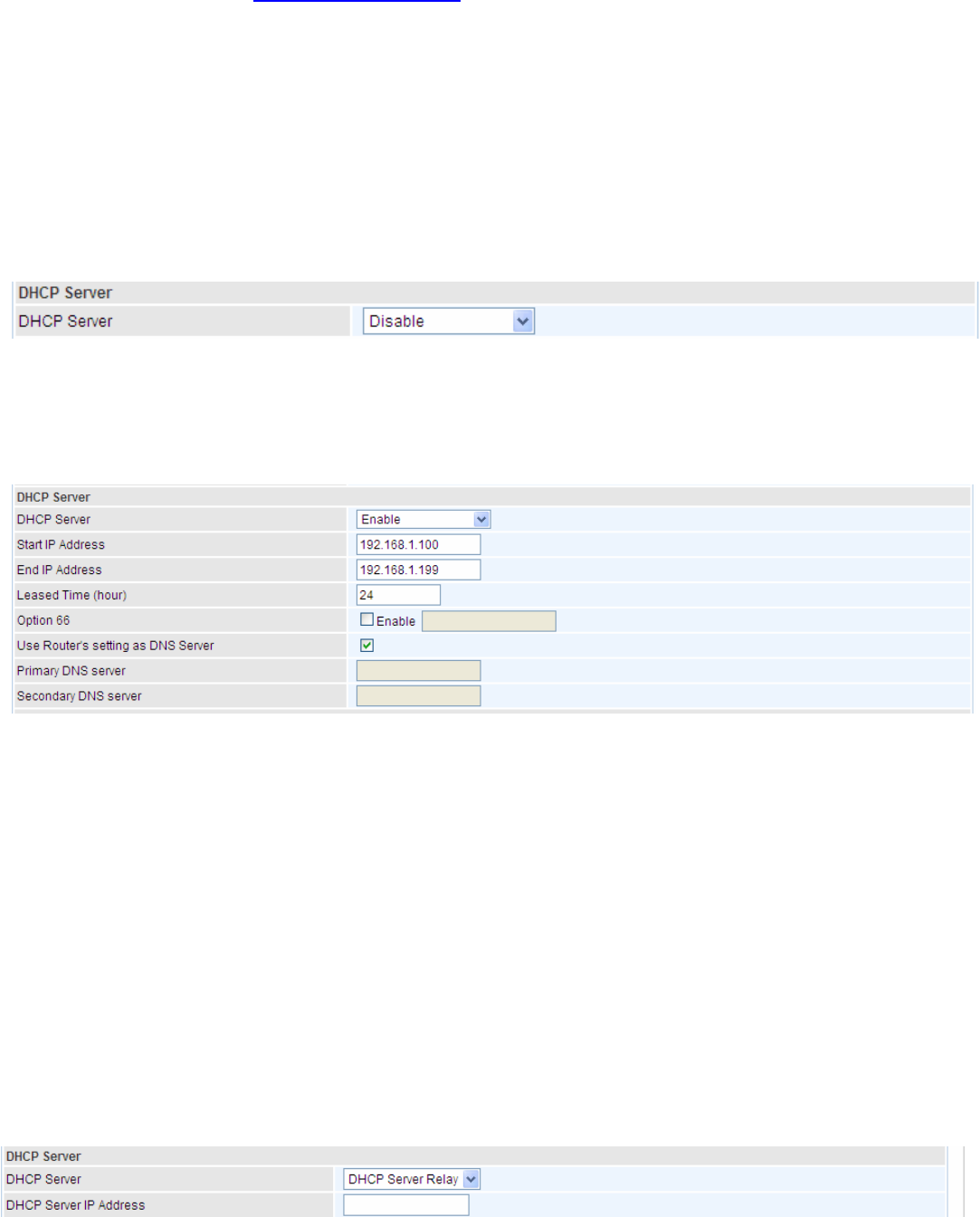
DHCP Server
You can disable or enable the DHCP (Dynamic Host Configuration Protocol) server or enable the
router’s DHCP relay functions. The DHCP protocol allows your router to dynamically assign IP
addresses to PCs on your network if they are configured to obtain IP addresses automatically.
L Disable
Disable the DHCP Server function.
L Enable
Enable the DHCP function, enter the information wanted. Here as default.
Start IP Address: The start IP address of the range the DHCP Server used to assign to the Clients.
End IP Address: The end IP address f the range the DHCP Server used to assign to the Clients.
Leased Time (hour): The leased time for each DHCP Client.
Option 66: Click Enable to activate DHCP option 66 for some special devices, like IPTV Set Box.
The devices can get firmware or some special service from the TFTP server. User needs to set the
IP or hostname of the TFTP server.
User Router’s setting as DNS server: Select whether to enable use router’s setting as DNS server,
if enabled, the PCs on the LAN side obtain the router’s setting as DNS server. If disabled, please
specify exactly the primary/secondary DNS server.
Primary/Secondary DNS server: Specify your primary/secondary DNS server for your LAN devices.
L DHCP Server Relay
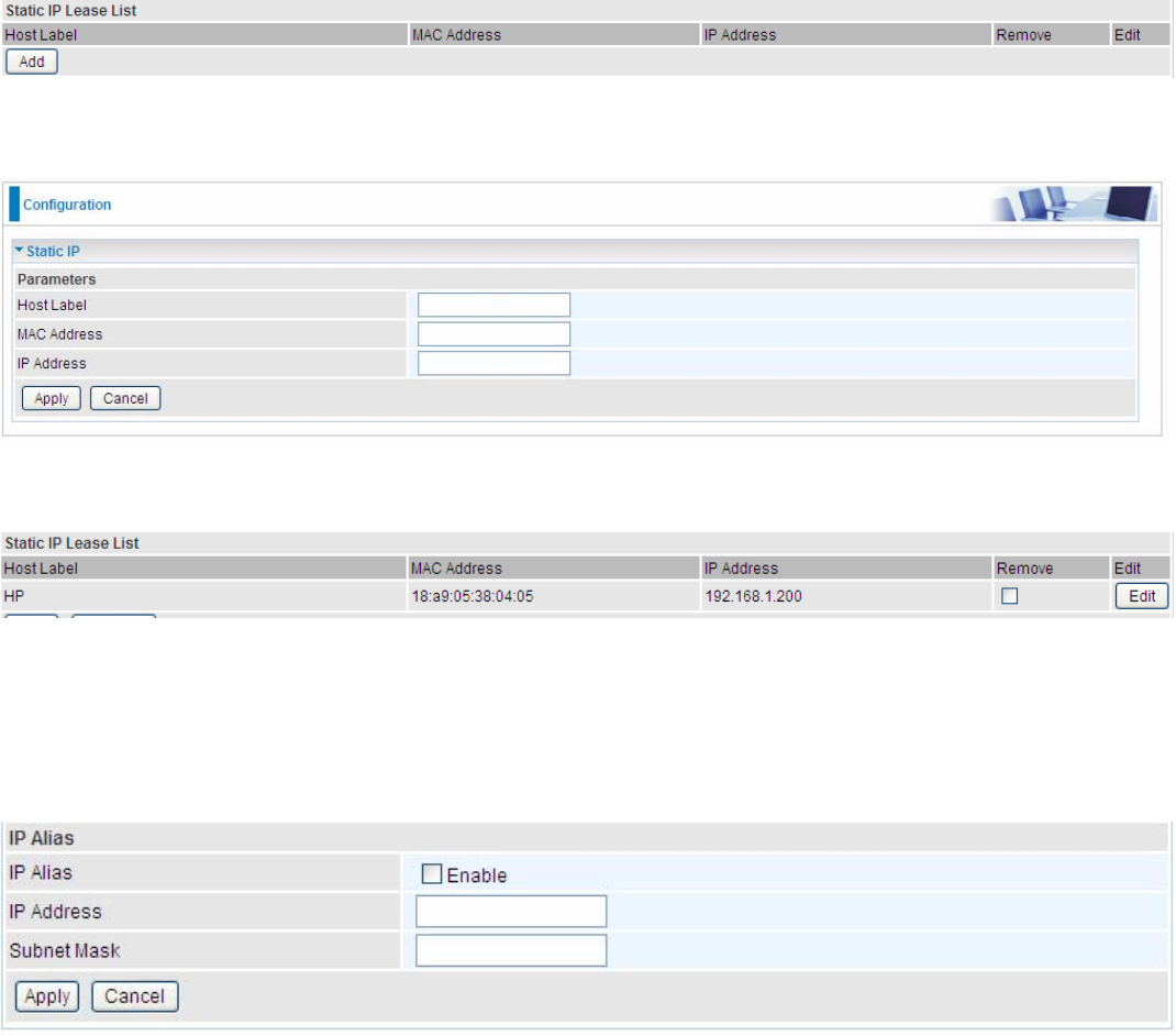
69
DHCP Server IP Address: Please enter the DHCP Server IP address.
Static IP Lease List
The specified IP will be assigned to the corresponding MAC Address listed in the following table
when DHCP Server assigns IP Addresses to Clients.
Press Add to the Static IP List.
Enter the MAC Address, IP Address, and then click Apply to confirm your settings. But the IP
assigned should be outside the range of 192.168.1.100-192.168.1.199.
IP Alias
This function allows the creation of multiple virtual IP interfaces on this router. It helps to connect two
or more local networks to the ISP or remote node.
IP Alias: Check whether to enable this function.
IP Address: Specify an IP address on this virtual interface.
Subnet Mask: Specify a subnet mask on this virtual interface.
Click Apply to apply your settings.
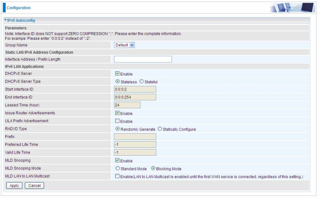
70
IPv6 Autoconfig
The IPv6 address composes of two parts, the prefix and the interface ID.
There are two ways to dynamically configure IPv6 address on hosts. One is “stateful” configuration,
for example using DHCPv6 (which resembles its counterpart DHCP in IPv4.) In the stateful auto-
configuration model, hosts obtain interface addresses and/or configuration information and
parameters from a DHCPv6 server. The Server maintains a database that keeps track of which
addresses have been assigned to which hosts.
The second way is “stateless” configuration. Stateless auto-configuration requires no manual
configuration of hosts, minimal (if any) configuration of routers, and no additional servers. The
stateless mechanism allows a host to generate its own addresses using a combination of locally
available information (MAC address) and information (prefix) advertised by routers. Routers
advertise prefixes that identify the subnet(s) associated with a link, while hosts generate an
"interface identifier" that uniquely identifies an interface on a subnet. An address is formed by
combining the two. When using stateless configuration, you needn’t configure anything on the client.
Group Name: Here group refers to the group you set in Interface Grouping section, you can set
the parameters for the specific group. Select the group by the drop-down box. For more
information please refer to Interface Grouping of this manual.
Static LAN IPv6 Address Configuration
Interface Address / Prefix Length: Enter the static LAN IPv6 address.
IPv6 LAN application
DHCPv6 Server: Check whether to enable DHCPv6 server.
71
DHCPv6 Server Type: Select Stateless or Stateful. When DHCPv6 is enabled, this parameter is
available. Stateless: If selected, the PCs in LAN are configured through RA mode, thus, the PCs in
LAN are configured through RA mode, to obtain the prefix message and generate an address using
a combination of locally available information (MAC address) and information (prefix) advertised by
routers, but they can obtain such information like DNS from DHCPv6 Server. Stateful: if selected,
the PCs in LAN will be configured like in IPv4 mode, thus obtain addresses and DNS information
from DHCPv6 server.
Start interface ID: Enter the start interface ID. The IPv6 address composed of two parts, thus, the
prefix and the interface ID. Interface is like the Host ID compared to IPv4.
End interface ID: Enter the end interface ID.
Note: Interface ID does NOT support ZERO COMPRESSION "::". Please enter the complete
information.
For example: Please enter "0:0:0:2" instead of "::2".
Leased Time (hour): The leased time, similar to leased time in DHCPv4, is a time limit assigned to
clients, when expires, the assigned ID will be recycled and reassigned.
Issue Router Advertisement: Check whether to enable issue Router Advertisement feature. It is to
send Router Advertisement messages periodically.
ULA Prefix Advertisement: Enable this parameter to include the ipv6 ULA address in the RA
messages. ULA, unique local address, is an IPv6 address in the block fc00::/7. It is approximately
the IPv6 counterpart of the IPv4 private address. They are not routable in the global IPv6 Internet.
RADVD Type: The way that ULA prefix is generated.
L Randomly Generated
L Statically Configured: select to set manually in the following parameters.
Prefix: Set the prefix manually.
Preferred Life Time: The ULA prefix life time. When the time is over, the ULA prefix is invalid any
more, -1 means no limit.
Valid Life Time: It is a time threshold, when the time is over, clients should obtain new IPv6 address
from the router through RA; -1 means to be limitless.
MLD snooping: Similar to IGMP snooping, listens in on the MLD conversation between hosts and
routers by processing MLD packets sent in a multicast network, and it analyzes all MLD packets
between hosts and the connected multicast routers in the network. Without MLD snooping, multicast
traffic is treated in the same manner as broadcast traffic - that is, it is forwarded to all ports. With
MLD snooping, multicast traffic of a group is only forwarded to ports that have members of that
group.
L Standard Mode: In standard mode, multicast traffic will flood to all bridge ports when no
client subscribes to a multicast group.
L Blocking Mode: In blocking mode, the multicast data will be blocked when there is no
client subscribes to a multicast group, it won’t flood to the bridge ports.
MLD LAN to LAN Multicast: Check to determine whether to support LAN to LAN (Intra LAN)
Multicast. If user want to have a multicast data source on LAN side and he want to get MLD
snooping enabled, then this LAN-to-LAN multicast feature should be enabled
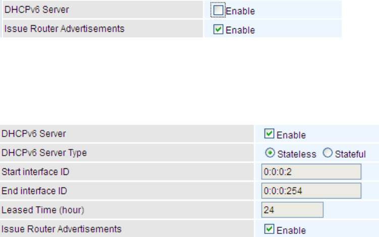
72
Stateless and Stateful IPv6 address Configuration
Stateless: Two methods can be carried.
L With DHCPv6 disabled, but Issue Router Advertisement Enabled
With this method, the PCs in LAN are configured through RA mode, thus, the PCs in LAN are
configured through RA mode, to obtain the prefix message and generate an address using a
combination of locally available information (MAC address) and information (prefix) advertised by
routers.
L With both DHCPv6 and Issue Router Advertisement Enabled
With this method, the PCs’ addresses in LAN are configured like above method, but they can
obtain such information like DNS from DHCPv6 Server.
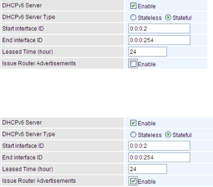
73
Stateful: two methods can be adopted.
L With only DHCPv6 enabled
With this method, the PCs’ addresses are configured the same as in IPv4, that is addresses are
assigned by DHCPv6 server.
L With both DHCPv6 and Issue Router Advertisement Enabled
With this method, the PCs’ addresses are configured the same like above, and the address
information in RA packets will be neglected.
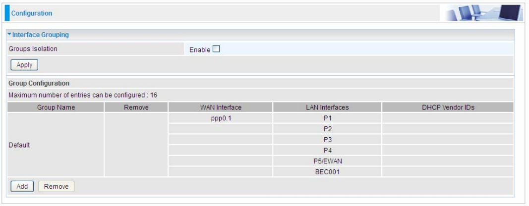
74
Interface Grouping
Interface grouping is a function to group interfaces, known as VLAN. A Virtual LAN, commonly known
as a VLAN, is a group of hosts with the common set of requirements that communicate as if they were
attached to the same broadcast domain, regardless of the physical location. A VLAN has the same
attributes as a physical LAN, but it allows for end stations to be grouped together even if they are not
located on the same network switch.
Each group will perform as an independent network. To support this feature, you must create
mapping groups with appropriate LAN and WAN interfaces using the Add button.
(Please Note: P5 can be configured as EWAN, and when the device is in EWAN profile, there is no
P5/EWAN interface as P5 is working as a WAN port.)
Groups Isolation: If enabled, devices in one group are not able to access those in the other group.
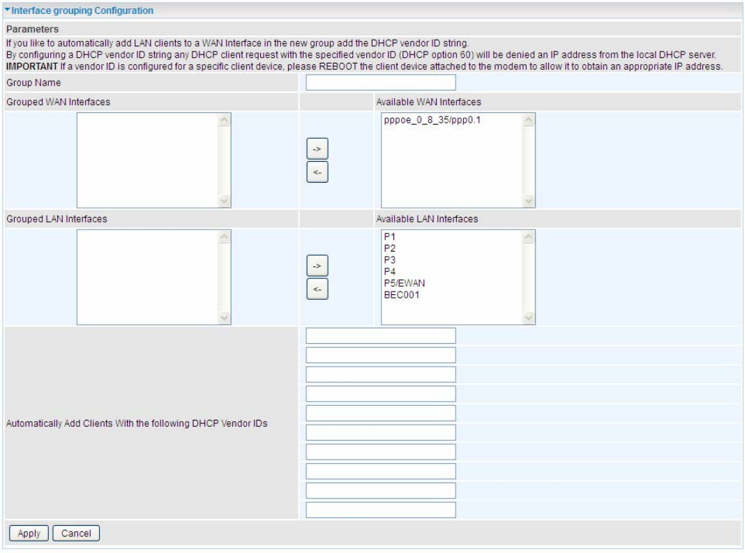
75
Click Add to add groups.
Group Name: Type a group name.
Grouped WAN Interfaces: Select from the box the WAN interface you want to applied in the group.
Grouped LAN Interfaces: Select the LAN interfaces you want to group as a single group from
Available LAN Interfaces.
Automatically Add Clients with following DHCP Vendor IDs: Enter the DHCP Vendor IDs for
which you want the Clients automatically added into the group. DHCP vendor ID (DHCP 60) is an
Authentication for DHCP Messages.
Click Apply to confirm your settings and your added group will be listed in the Interface Grouping
table below.
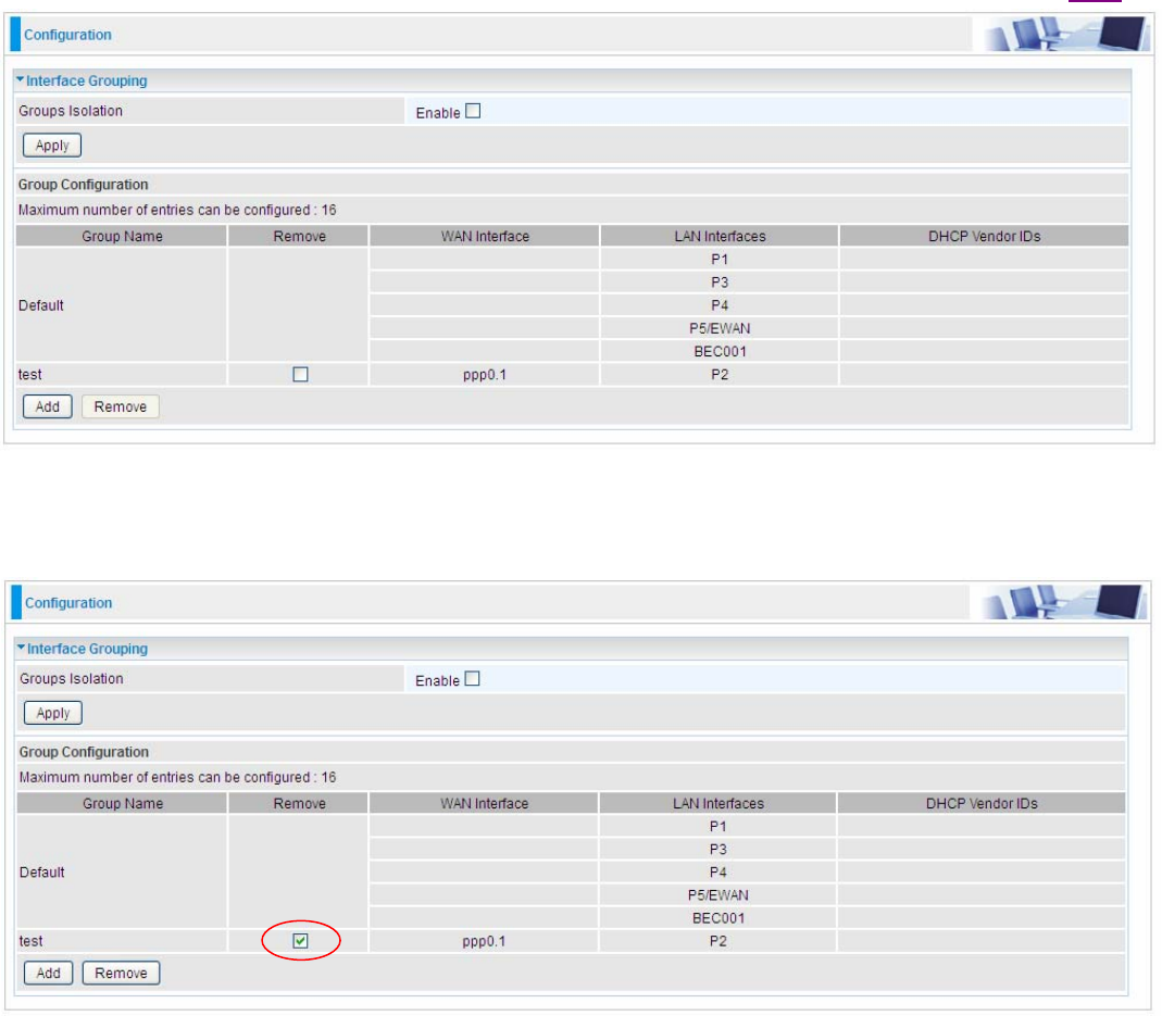
76
In group "test", P2 and PPP0.1 are grouped in one group, they have their only network , see LAN.
If you want to remove the group, check the box as the following and press Remove.
Note: If you like to automatically add LAN clients to a WAN Interface in the new group add the
DHCP vendor ID string.
By configuring a DHCP vendor ID string any DHCP client request with the specified vendor
ID (DHCP option 60) will be denied an IP address from the local DHCP server.
If a vendor ID is configured for a specific client device, please REBOOT the client device
attached to the modem to allow it to obtain an appropriate IP address.
Each LAN interface can only be added into one group and one WAN interface can only be
used in one group.
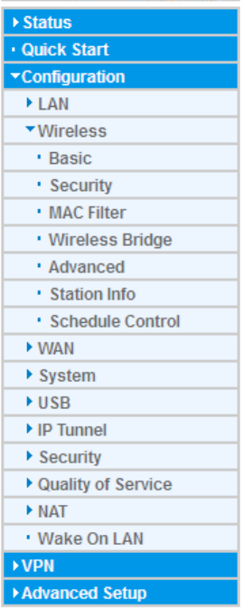
77
Wireless
This section introduces the wireless LAN and some basic configurations.
Wireless LANs can be as complex as a number of computers with wireless LAN cards
communicating through access points which bridge network traffic to the wired LAN. It allows
multiple wireless users in 2.4G radio band to surf the Internet, checking e-mail, watching video,
listening to music over the Internet concurrently.
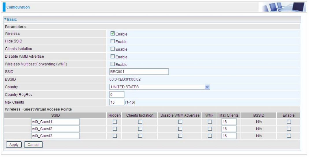
78
Basic
It let you determine whether to enable Wireless function and set the basic parameters of an AP and
the Virtual APs.
Wireless: Default setting is set to Enable. If you do not have any wireless devices, check the
checkbox again to unselect.
Hide SSID: It is function in which transmits its SSID to the air so that when wireless client searches
for a network, router can then be discovered and recognized. Check the checkbox to determine
whether you want to hide SSID.
Clients Isolation: if you enabled this function, then each of your wireless clients will not be able to
communicate with each other.
Disable WMM Advertise: Stop the router from ‘advertising’ its Wireless Multimedia (WMM)
functionality, which provides basic quality of service for time-sensitive applications (e.g. VoIP, Video).
Check to disable or enable this function.
Wireless multicast Forwarding (WMF): check to enable or disable wireless multicast forwarding.
SSID: The SSID is the unique name of a wireless access point (AP) to be distinguished from another.
For security purpose, change the default o a unique ID name to the AP already built-in to the router’s
wireless interface. It is case sensitive and must not excess 32 characters. Make sure your wireless
clients have exactly the SSID as the device, in order to get connected to your network.
Note: SSID is case sensitive and must not exceed 32 characters.
BSSID: Basic Set Service Identifier, it is a local managed IEEE MAC address, and is 48 bits value.
Country: Different countries have different wireless band resources, so you can select the
appropriate Country according to your location.
Country RegRev: The regulatory revision number, together with the country set in the above
country field to uniquely mark a specific location. For example, US/3.
Max Clients: enter the number of max clients the wireless network can supports,1-16.
Guest/virtual Access Points: A “Virtual Access Point” is a logical entity that exists within a physical
Access Point (AP). When a single physical AP supports multiple “Virtual APs”, each Virtual AP
appears to stations (STAs) to be an independent physical AP, even though only a single physical AP
79
is present. For example, multiple Virtual APs might exist within a single physical AP, each advertising
a distinct SSID and capability set. Alternatively, multiple Virtual APs might advertise the same SSID
but a different capability set – allowing access to be provided via Web Portal, WEP, and WPA
simultaneously. Where APs are shared by multiple providers, Virtual APs provide each provider with
separate authentication and accounting data for their users, as well as diagnostic information,
without sharing sensitive management traffic or data between providers. You can enable the virtual
AP.
Here you can enable some Virtual APs according to the request. And the other parameters of virtual
APs are the same to the above.
Click Apply to apply your settings.
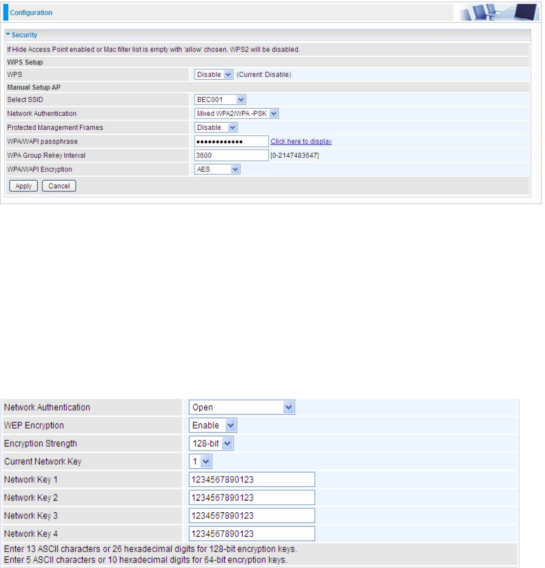
80
Security
Wireless security prevents unauthorized access or damage to computers using wireless network.
Note:
The WPS feature will also be unavailable when the security setting is not WPA2 or OPEN. So, if you
manually set the wireless security setting, you should give notice to it, but you can find prompt
indicating configuration.
Manual Setup AP
Select SSID: select the SSID you want these settings apply to.
Network Authentication
L Open
WEP Encryption: Select to enable or disable WEP Encryption. Here select Enable.
Encryption Strength: Select the strength, 128-bit or 64-bit.
Current Network Key: Select the one to be the current network key. Please refer to key 1- 4 below.
Network Key (1- 4): Enter 13 ASCII characters or 26 hexadecimal digits for 128-bit encryption keys.
Enter 5 ASCII characters or 10 hexadecimal digits for 64-bit encryption keys.
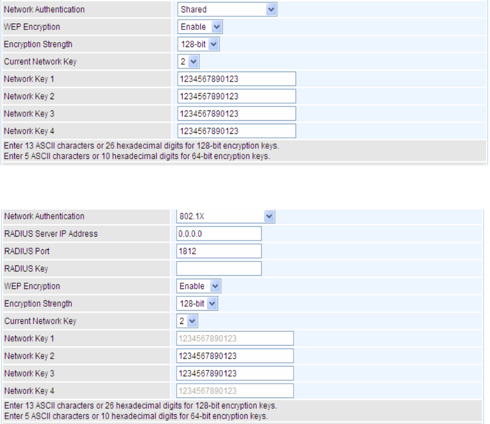
81
L Shared
This is similar to network authentication ‘Open’. But here the WEP Encryption must be enabled.
L 802.1x
RADIUS Server IP Address: RADIUS( Remote Authentication Dial In User Service), Enter the
IP address of RADIUS authentication server.
RADIUS Port: Enter the port number of RADIUS authentication server here.
RADIUS Key: Enter the password of RADIUS authentication server.
WEP Encryption: Select to enable or disable WEP Encryption. Here select Enable.
Current Network Key: Select the one to be the current network key. Please refer to key 2- 3 below.
Network Key (1- 4): Enter 13 ASCII characters or 26 hexadecimal digits for 128-bit encryption keys.
Enter 5 ASCII characters or 10 hexadecimal digits for 64-bit encryption keys.
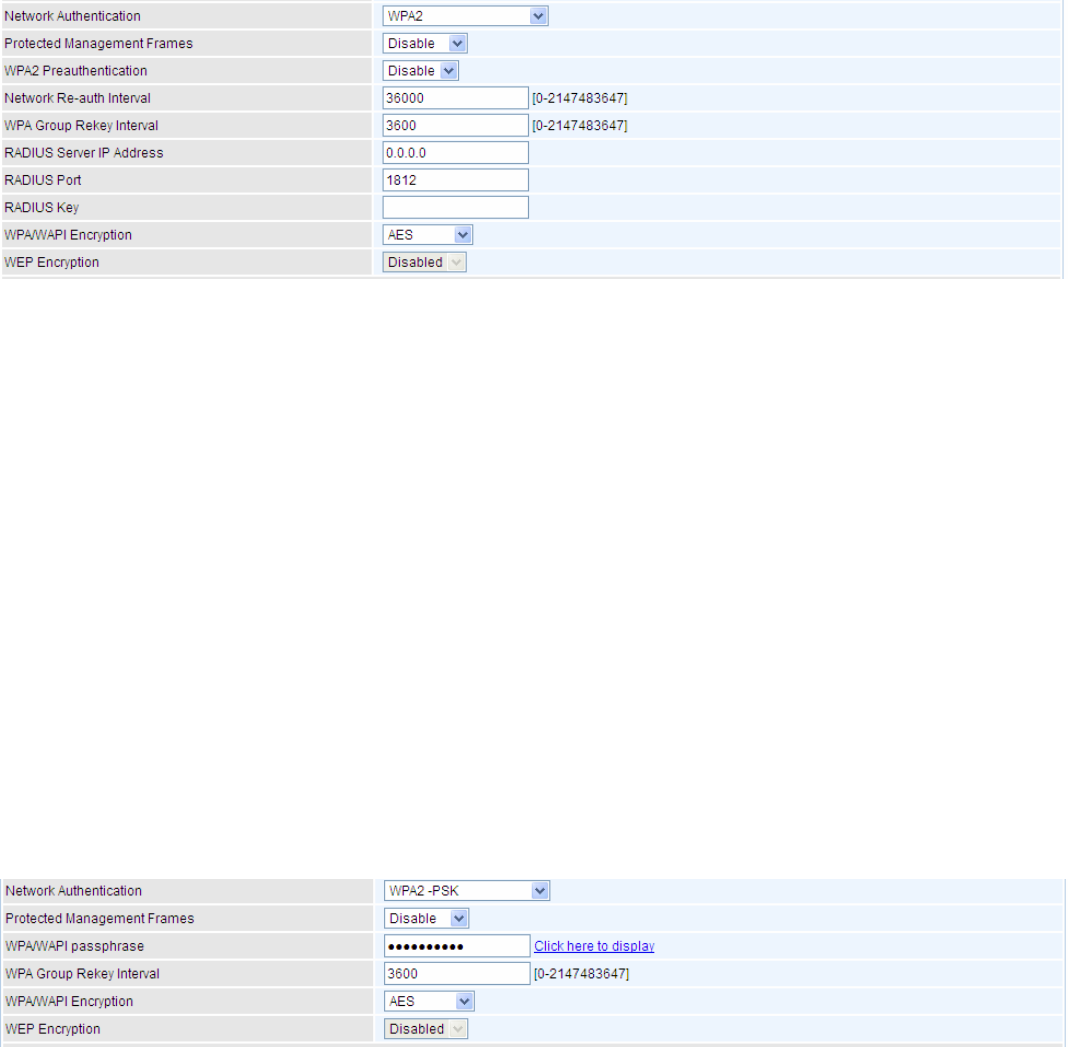
82
L WPA2
Protected Management Frame: Select whether to enable protected management frame
mechanism. By default, it is disabled. If enabled, the network adapter of the attempting wireless
client should also support this feature.
WPA2 Preauthentication: When a wireless client wants to handoff to another AP, with
preauthentication, it can perform 802.1X authentication to the new AP, and when handoff happens,
this mode will help reduce the association time.
Network Re-auth Interval: the interval for network Re-authentication. This is in seconds.
WPA Group ReKey Internal: The period of renewal time for changing the security key automatically
between wireless client and Access Point (AP). This is in seconds.
RADIUS Server IP Address: RADIUS( Remote Authentication Dial In User Service), Enter the
IP address of RADIUS authentication server. This is in seconds.
RADIUS Port: Enter the port number of RADIUS authentication server here.
RADIUS Key: Enter the password of RADIUS authentication server.
WPA/WAPI Encryption: There are two Algorithms, AES (Advanced Encryption Standard) and
TKIP(Temporal Key Integrity Protocol) which help to protect the wireless communication.
L WPA2-PSK
Protected Management Frame: Select whether to enable protected management frame
mechanism. By default, it is disabled. If enabled, the network adapter of the attempting wireless
client should also support this feature.
WPA/WAPI passphrase: Enter the WPA.WAPI passphrase; you can click here to display to view it.
WPA Group ReKey Internal: The period of renewal time for changing the security key automatically
between wireless client and Access Point (AP). This is in seconds.
WPA/WAPI Encryption: There are two Algorithms, AES (Advanced Encryption Standard) and
TKIP(Temporal Key Integrity Protocol) which help to protect the wireless communication.
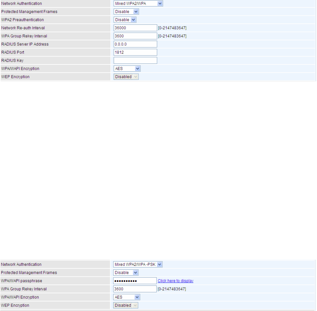
83
L Mixed WPA2/WPA
Protected Management Frame: Select whether to enable protected management frame
mechanism. By default, it is disabled. If enabled, the network adapter of the attempting wireless
client should also support this feature.
WPA2 Preauthentication: When a wireless client wants to handoff to another AP, with
preauthentication, it can perform 802.1X authentications to the new AP, and when handoff happens,
this mode will help reduce the association time used.
Network Re-auth Interval: the interval for network Re-authentication. The unit is second.
WPA Group ReKey Internal: The period of renewal time for changing the security key automatically
between wireless client and Access Point (AP). This is in seconds.
RADIUS Server IP Address: RADIUS( Remote Authentication Dial In User Service), Enter the
IP address of RADIUS authentication server.
RADIUS Port: Enter the port number of RADIUS authentication server here.
RADIUS Key: Enter the password of RADIUS authentication server.
WPA/WAPI Encryption: There are two Algorithms, AES (Advanced Encryption Standard) and
TKIP(Temporal Key Integrity Protocol) which help to protect the wireless communication.
L Mixed WPA2/WPA-PSk
Protected Management Frame: Select whether to enable protected management frame
mechanism. By default, it is disabled. If enabled, the network adapter of the attempting wireless
client should also support this feature.
WPA/WAPI passphrase: enter the WPA.WAPI passphrase, you can click here to display to view it.
WPA Group ReKey Internal: The period of renewal time for changing the security key automatically
between wireless client and Access Point (AP). The unit is second.
WPA/WAPI Encryption: There are two Algorithms, AES (Advanced Encryption Standard) and
TKIP(Temporal Key Integrity Protocol) which help to protect the wireless communication.
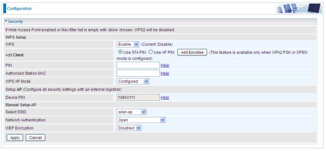
84
WPS Setup
WPS (Wi-Fi Protected Setup) feature is a standard protocol created by Wi-Fi Alliance. WPS is used
to exchange the AP setting with Station and configure Ap settings. This feature greatly simplifies the
steps needed to create a Wi-Fi network for a residential or an office setting. The commonly known
PIN method is supported to configure WPS.
WPS: Select enable to enable WPS function. Please note that WPS can only be available when
WPA2-PSK or OPEN mode is configured.
Note:
1) WPS feature is only available when in WPA2 or OPEN mode in security settings.
2) Here wireless can be configured as Registrar and Enrollee mode respectively. When AP is
configured as Registrar, you should select “Configured” in the WPS AP Mode below, and default
WPS AP Mode is “Configured”. When AP is configured as Enrollee, the WPS AP Mode below
should be changed to “Unconfigured”. Follow the following steps.
Change the SSID to “wlap-ap” for examples on WPS usage. The SSID change is only for example,
users can change to whatever desired in wireless Basic configuration section.
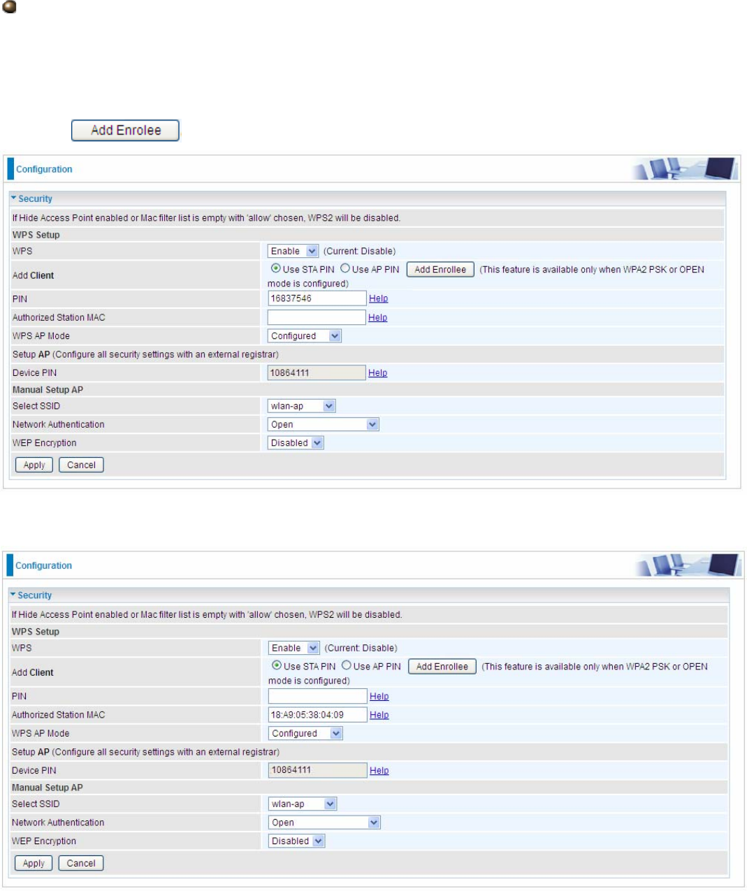
85
Configure AP as Registrar
Add Enrollee with PIN method
1. Select radio button “Use STA PIN”.
2. Input PIN from Enrollee Station (16837546 in this example), Or else users can alternatively
enter the authorized station MAC Help: it is to help users to understand the concept and correct
operation.
3. Click .
(Station PIN)
(Station MAC)
Note: Users can alternatively input PIN from Enrollee Station or enter the authorized station MAC.
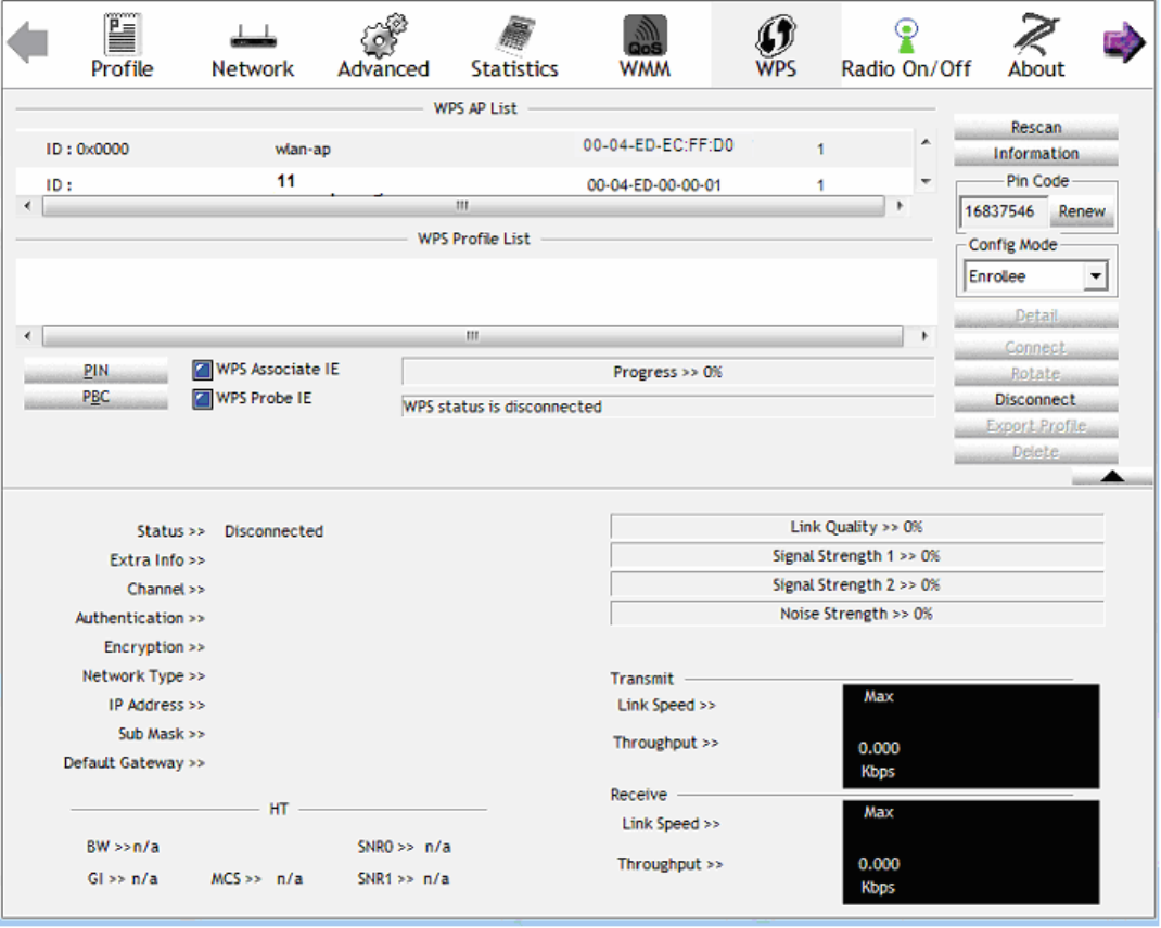
86
4. Operate Station to start WPS Adding Enrollee. Launch the wireless client’s WPS utility (eg.Ralink
Utility). Set the Config Mode as Enrollee, press the WPS button on the top bar, select the AP (eg.
wlan-ap) from the WPS AP List column. Then press the PIN button located on the middle left of
the page to run the scan.
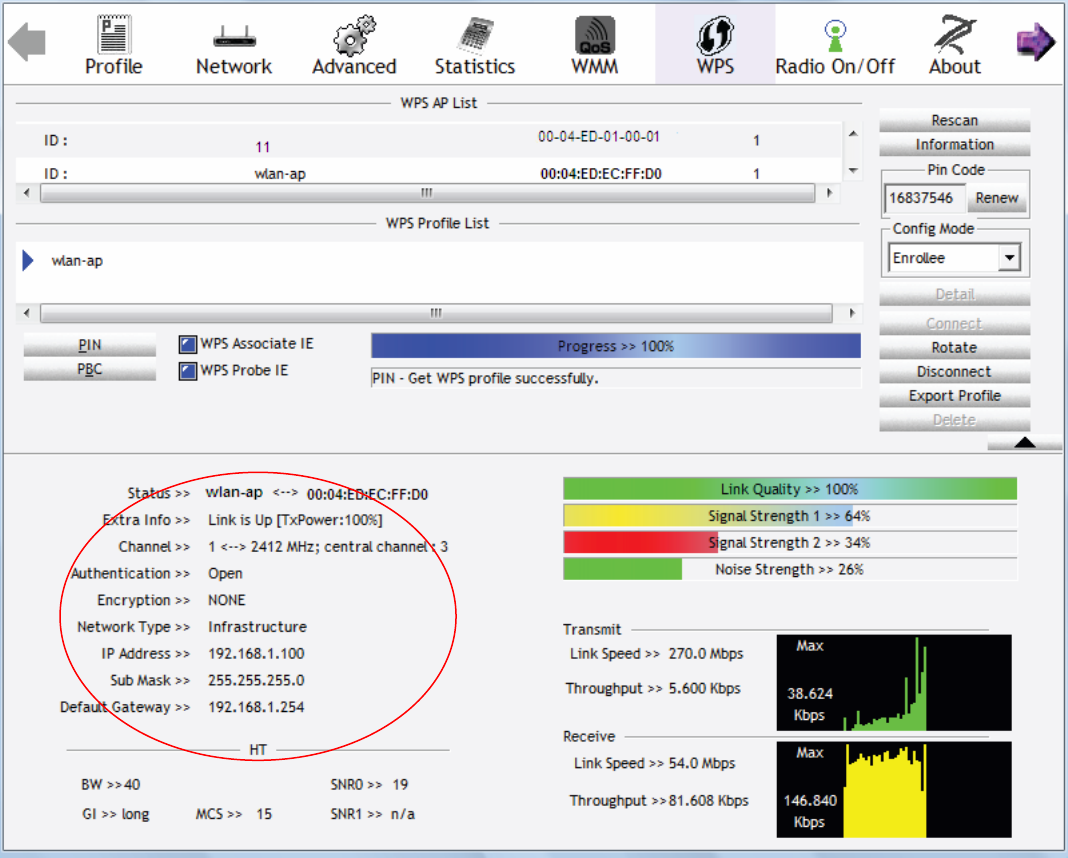
87
4. The client’s SSID and security settings will now be configured to match the SSID and security
settings of the registrar.
You can check the message in the red ellipse with the security parameters you set, here we all use
the default.
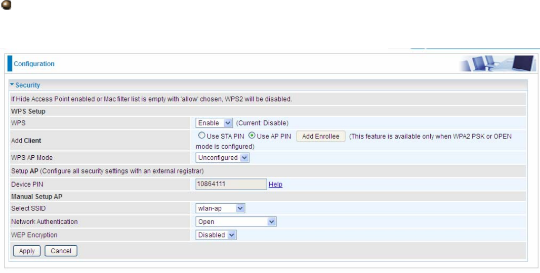
88
Configure AP as Enrollee
Add Registrar with PIN Method
1. Set AP to “Unconfigured Mode”.
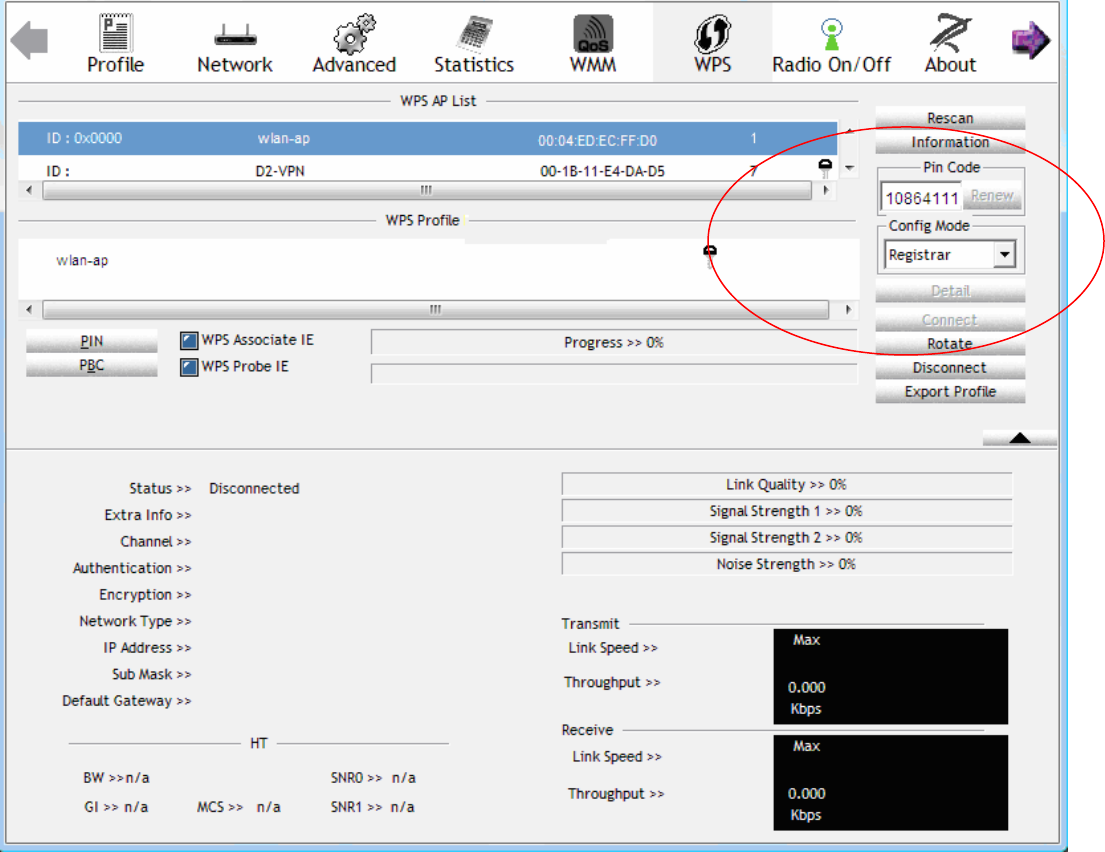
89
2. Launch the wireless client’s WPS utility (eg. Ralink Utility). Set the Config Mode as Registrar.
Enter the PIN number (10864111 (device) for example) in the PIN Code column then choose the
correct AP (eg. wlan-ap) from the WPS AP List section before pressing the PIN button to run the
scan.
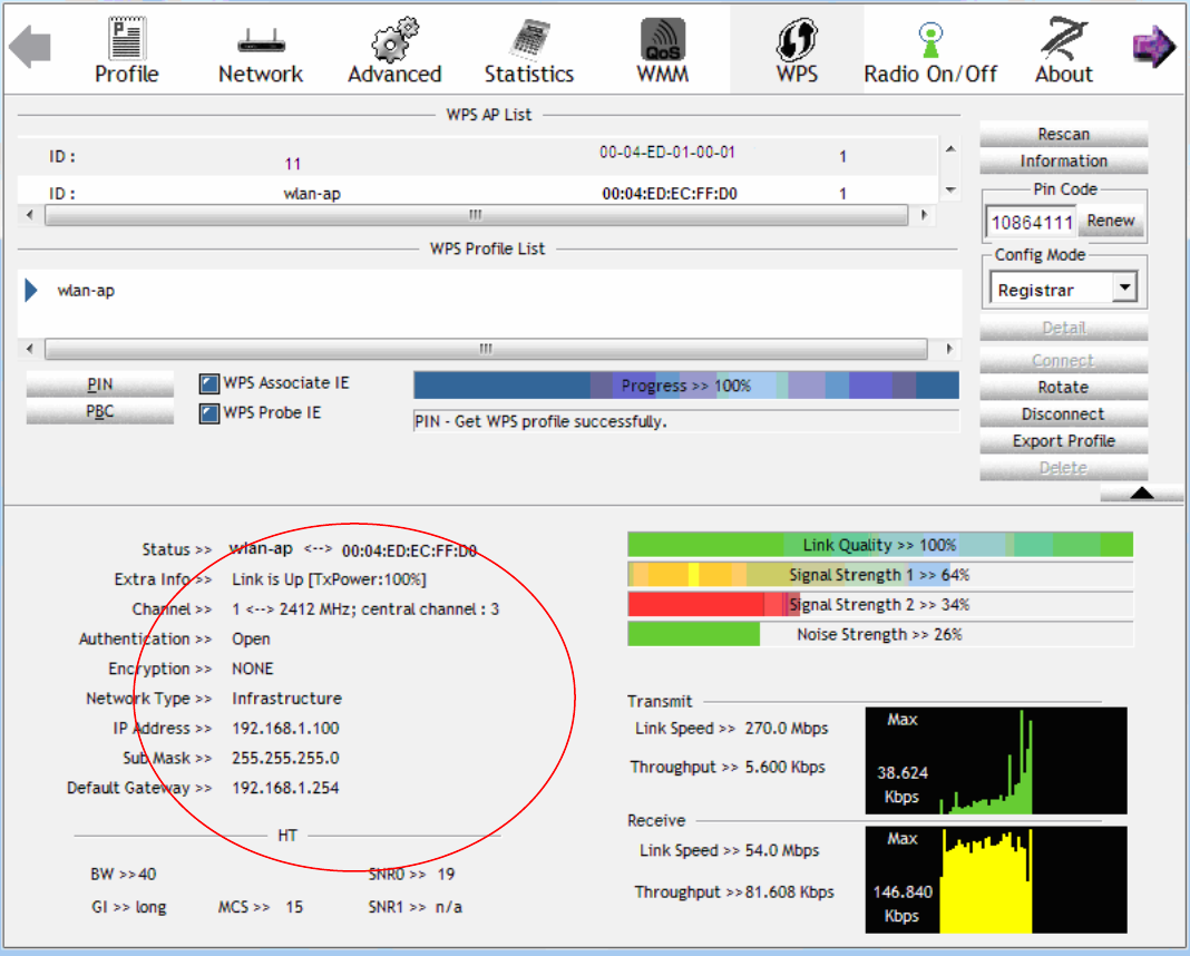
90
3. The router’s (AP’s) SSID and security setting will now be configured to match the SSID and
security setting of the registrar.
4. Do Web Page refresh after ER complete AP Configuration to check the new parameters setting.
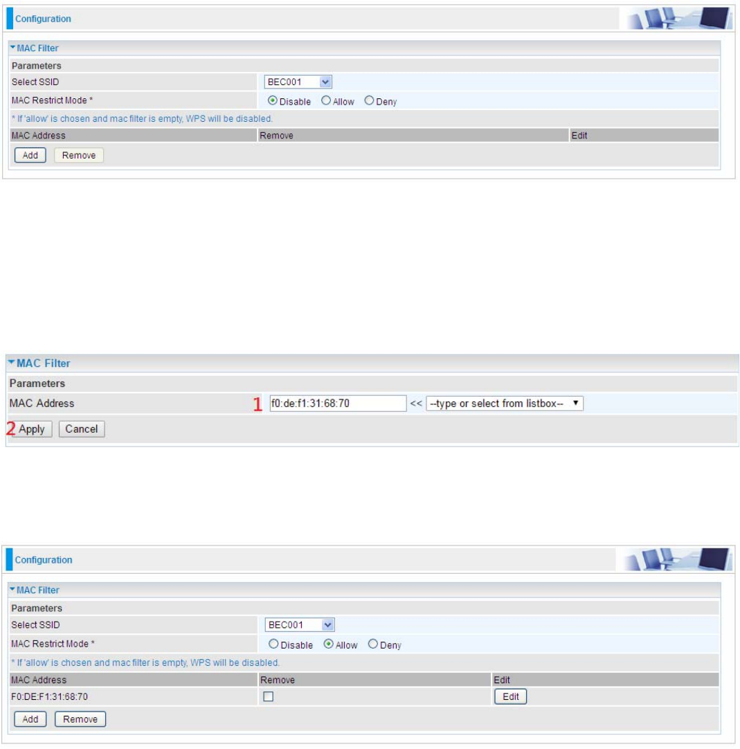
91
MAC Filter
Select SSID: select the SSID you want this filter applies to.
MAC Restrict Mode:
L Disable: disable the MAC Filter function.
L Allow: allow the hosts with the following listed MACs to access the wireless network.
L Deny: deny the hosts with the following listed MACs to access the wireless network.
Click Add to add the MACs.
MAC Address: enter the MAC address(es). The format of MAC address could be: xx:xx:xx:xx:xx:xx
or xx-xx-xx-xx-xx-xx.
Click Apply to apply your settings and the item will be listed below.
To delete entries , check the remove checkbox and press Remove to delete it.
To make changes, click Edit of a MAC address to reconfigure the MAC as needed.
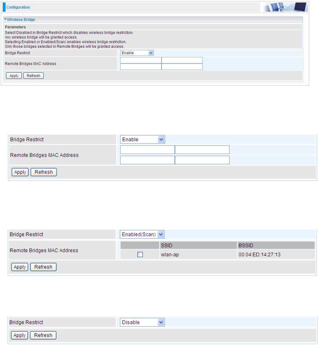
92
Wireless Bridge
WDS (wireless distributed system) is a wireless access point mode that enables wireless link and
communication with other access points. It’s easy to install, simply define the peer’s MAC address of
the connected AP. WDS takes advantage of cost saving and flexibility with no extra wireless client
device required to bridge between two access points and extending an existing wired or wireless
infrastructure network to create a larger network.
Bridge Restrict: Set to enable or disable the WDS function.
L Enable: to enable wireless bridge restriction. Only those specified in the Remote MAC
Address the gateway can communicate with.
Remote Bridge MAC Address: enter the remote bridge MAC addresses. Here up to 4 bridge
MAC addresses are supported.
L Enabled (Scan): to enable wireless bridge restriction. Only those scanned by the gateway
can communicate.
Remote Bridge MAC Address: select the remote bridge MAC addresses.
L Disable: Does not restrict the gateway communicating with bridges that have their MAC
address listed, but it is still open to communicate with all bridges that are in the same network.
Click Apply to apply your settings.
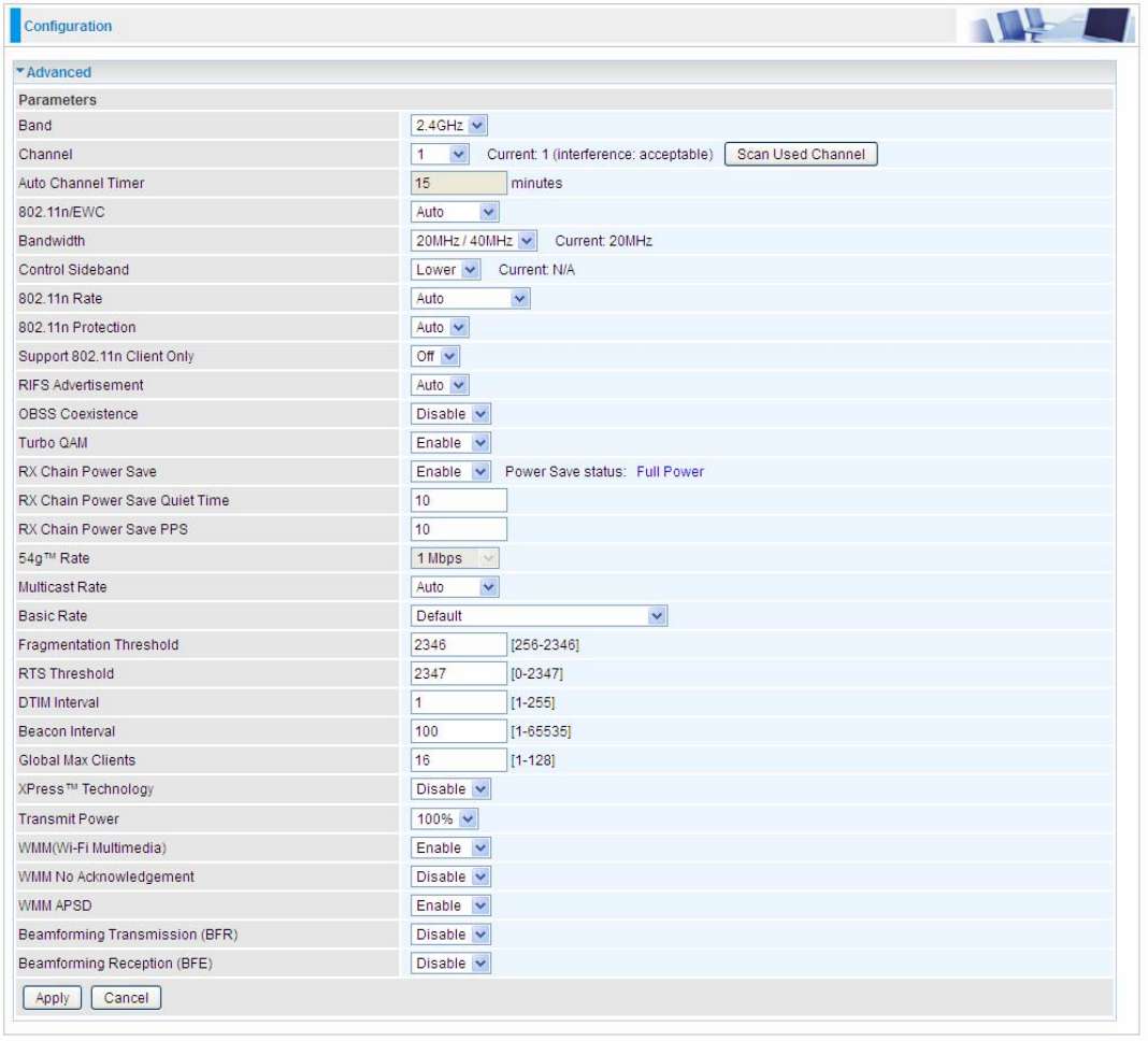
93
Advanced
Band: In the 2.4 GHz radio frequency.
Channel: Choose a channel to use. Here is a list of available channels or select Auto mode instead.
Scan Used Channel: Press the button to scan and list all channels being used.
Auto Channel Timer (min): Available when Auto Channel is selected. The auto channel times
length it takes to scan in minutes.
802.11n/EWC: select to auto enable or disable 802.11n.
Bandwidth: The higher the bandwidth the better the performance will be but greater interference
with other wireless devices. Select 20MHz for lessen radio interference.
Control Sideband: only available for 40MHz. It allows you to select upper sideband or lower
sideband. Sideband refers to the frequency band either above (upper sideband) or below (lower
sideband) the carrier frequency, within which fall the spectral components produced by modulation
of a carrier wave.
802.11n Rate: This allows you to select the fixed transmission rate or auto.
802.11n Protection: turn off for maximize throughput.
Support 802.11n Client Only: turn on the option to only provide wireless access to the clients
94
operating at 802.11n speeds.
RIFS Advertisement: Reduced Inter-frame Spacing (RIFS) is an 802.11n feature that also improves
performance by reducing the amount of dead time required between OFDM transmissions. Select
Off to disable this function or auto to enable this function.
OBSS Coexistence: coexistence (or not) between 20 MHZ and 40 MHZ overlapping basic service
sets (OBSS) in wireless local area networks.
Turbo QAM
RX Chain Power Save: Enabling this feature turns off one of the Receive chains, going from 2x2 to
2x1 to save power.
RX Chain Power Save Quiet Time: The number of seconds the traffic must be below the PPS
value before the Rx Chain Power Save feature activates itself.
RX Chain Power Save PPS: The maximum number of packets per seconds that can be processed
by the WLAN interface for duration of Quiet Time, described above, before the Rx Chain Power
Save feature activates itself.
54g™ Rate: Available after changing 802.11n Rate to “Use 54g Rate” in 802.11n Rate. It is used to
limit 11n speed to a specific rate, e.g. 1M, 6M, 12M, 24M, 48M, etc.
Multicast Rate: Setting for multicast packets transmission rate.
Basic Rate: Setting for basic transmission rate. It is not a specific kind of rate, it is a series of rates
supported. When set to Default, the router can transmit with all kinds of standardized rates.
Fragmentation Threshold: A threshold (in bytes) whether the packets will be fragmented and at
what size. Packets succeeding the fragmentation threshold of 802.11n WLAN will be split into
smaller units suitable for circuit size. While the packets smaller than fragmentation threshold will not
be fragmented. Default is 2346, setting the fragmentation too low may result in poor performance.
RTS Threshold: Request to Send (RTS) threshold specifies the packet size, when exceeds the size,
the RTS/CTS will be triggered. The default setting of 2347(max length) will disable the RTS.
DTIM Interval: Delivery Traffic Indication Message (DTIM). The entry range is a value between 1
and 255. A DTIM is countdown variable that informs clients of the next window for listening to
broadcast and multicast messages. When the AP has buffered broadcast or multicast messages for
associated clients, it sends the next DTIM with a DTIM interval value. AP clients hear the beacons
and awaken to receive the broadcast and multicast messages. The default is 1.
Beacon Interval: The amount of time between beacon transmissions in is milliseconds. The default
is 100ms and the acceptable is 1- 65535. The beacon transmissions identify the presence of an
access point.
Global Max Clients: Here you have the option of setting the limit of the number of clients who can
connect to your wireless network.
XPress™ Technology: It has been designed to improve the wireless network efficiency. Default is
disabled.
Transmit Power: select the transmitting power of your wireless signal.
WMM (Wi-Fi Multimedia): you can choose to enable or disable this function which allows for priority
of certain data over wireless network.
WMM No Acknowledgement: Refers to the acknowledge policy at the MAC level. Enabling WMM
No Acknowledgement can result in more efficient throughput but higher error rates in noisy Radio
Frequency (RF) environment.
WMM APSD: Automatic Power Save Delivery. Enable this to save power.
Beamforming Transmission (BFR) / Beamforming Reception (BFE): Enable to increase wireless
speed by focusing and concentrating transmitted (send) and/or receive signals with a wireless client
instead of broadcast signals in all directions. Note: Both router and client wireless must support
beamforming technology.
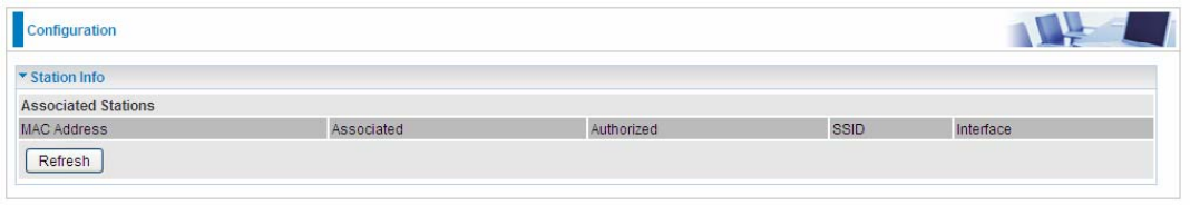
95
Station Info
Here you can view information about the wireless clients.
MAC Address: The MAC address of the wireless clients.
Associated: List all the stations that are associated with the Access Point. If a station is idle for too
long, it is removed from this list
Authorized: List those devices with authorized access.
SSID: Show the current SSID of the client.
Interface: To show which interface the wireless client is connected to.
Refresh: To get the latest information.
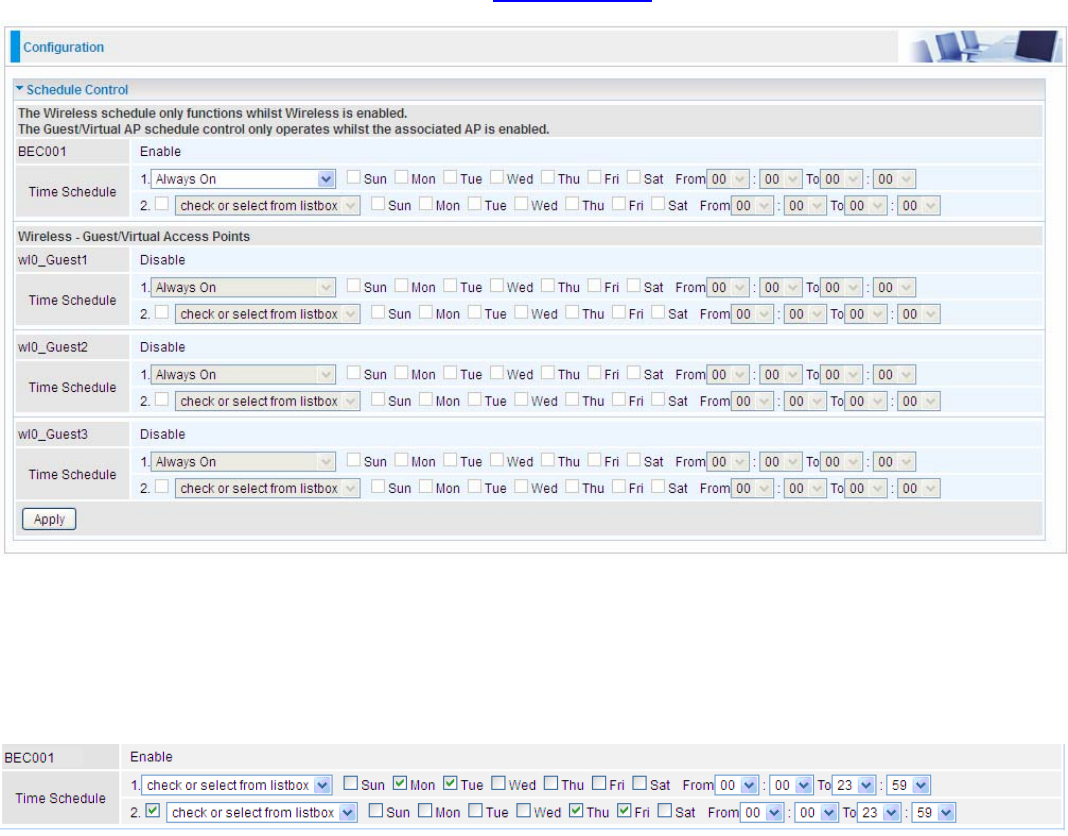
96
Schedule Control
Schedule control is aimed to offer methods to flexibly control when the wireless network (SSID) is
allowed for access.
The Wireless schedule only functions whilst Wireless is enabled.
The Guest/Virtual AP schedule control only operates whilst the associated AP is enabled.
For detail setting the timeslot, user can turn to Time Schedule .
Time Schedule: Set when the SSID works. If user wants the SSID works all the time, please select
“Always On”; if not, please set or select the exact time your want the SSID works. Here user can set
two separate intervals.
For example: user wants the SSID “BEC001” to work on weekdays except for Wednesday, under
this circumstance, user can set as shown below. (8920NXL-600 offers a optimal way to set two
separate timeslots when user needs to activate the SSID during separate intervals. )
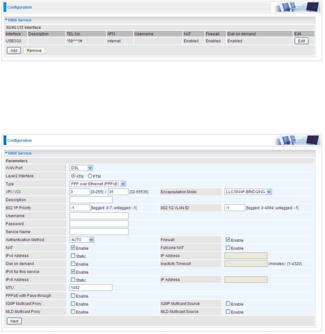
97
WAN-Wide Area Network
A WAN (Wide Area Network) is a computer network that covers a broad geographical area (eg.
Internet) that is used to connect LAN and other types of network systems.
WAN Service
Three WAN interfaces are provided for WAN connection: DSL (VDSL/ADSL), Ethernet and 3G/4G
LTE.
Click Add to add new WAN connections.
L DSL
In DSL mode, there are two transfer modes for you to configure for WAN connection, namely ATM
(ADSL) and PTM (VDSL) configuration of PTM mode is similar as ATM mode, here take ATM mode
WAN configuration for example.
Layer2 Interface: 2 transfer mode, ATM or PTM.
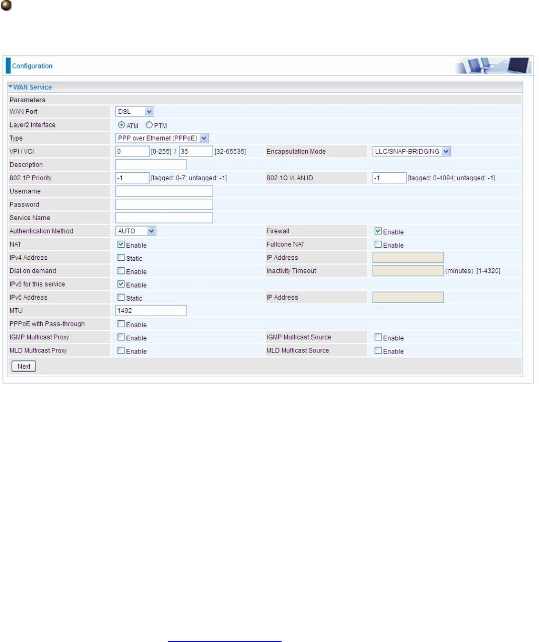
98
PPPoE
PPPoE (PPP over Ethernet) provides access control in a manner which is similar to dial-up services
using PPP.
VPI/VCI: Enter the VPI/VCI combination from you ISP.
Encapsulation Mode: Select the encapsulation mode, LLC/SNAP-BRIDGING, or VC/MUX.
Description: User-defined description for the connection, commonly for friendly use.
802.1P Priority: The parameter indicates the frame priority level from 0 (lowest) to 7 (highest), which
can be used to prioritize different classes of traffic (voice, video, data, etc). Enter the priority
identification, tagged: 0-1, untagged: -1.
802.1Q VLAN ID: It is a parameter to specify the VLAN which the frame belongs. Enter the VLAN ID
identification, tagged: 0-4094, untagged : -1.
Username: Enter the account obtained from the ISP.
Password: Enter the password obtained from the ISP.
Service Name: The item is for identification purposes, user can define this.
Authentication Method: Default is Auto. Or else your ISP will advise you the appropriate mode.
Firewall: Enable to drop all traffic from WAN side. If enabled, all incoming packets by default would
be dropped, and please turn to IP Filtering Incoming to add allowing rules.
NAT: The NAT (Network Address Translation) feature allows multiple users to access the Internet
through a single IP account by sharing the single IP address. If users on your LAN have their own
public IP addresses to access the Internet, NAT function can be disabled. When enabled, a Fullcone
NAT parameter will appear, you can determine whether to enable Fullcone NAT. While only NAT
enabled, the default NAT type Port-Restricted cone NAT will be used.
Fullcone NAT: Enable or disable fullcone NAT. Fullcone is a kind of NAT, in this mode, all requests
from the same internal IP address and port are mapped to the same external IP address and port.
99
Furthermore, any external host can send a packet to the internal host, by sending a packet to the
mapped external address.
Note: In PPPoE connection, NAT is enabled by default, you can determine whether to enable
Fullcone NAT or disable Fullcone NAT and only use NAT, the default NAT type is Port Restricted
cone NAT. Of Port-Restricted cone NAT, the restriction includes port numbers. Specifically, an
external host can send a packet, with source IP address X and source port P, to the internal host
only if the internal host had previously sent a packet to IP address X and port P
IPv4 Address: Select whether to set static IPv4 address or obtain automatically.
IP Address: If Static is enabled in the above field, enter the static IPv4 address get from the ISP.
Dial on demand: It is a parameter to let users to dial for connection to internet themselves. It is
useful when saving internet fees.
Inactivity Timeout: The set Inactivity timeout period, unit: minutes. It is combined use with Dial on
Demand, users should specify the concrete time interval for dial on demand.
IPv6 for this service: Enable to use IPv6 service.
IPv6 Address: Select whether to set static IPv6 address or obtain automatically.
IP Address: If Static is enabled in the above field, enter the static IPv4 address.
MTU: Maximum Transmission Unit, the size of the largest datagram (excluding media-specific
headers) that IP will attempt to send through the interface.
PPPoE with Pass-through: Enable or disable PPPoE pass-through. If it is enabled, PCs behind the
router can dial itself.
IGMP Multicast Proxy: Check whether to enable this feature. IGMP (Internet Group Management
Protocol) Proxy intercepts the IGMP request from Clients and set up the multicast-forwarding table,
it takes over some of the router’s job, simplifying the router’s job and multicast communication.
IGMP Multicast Source: Enable to support the “source filtering” which is the ability for a system to
report interest in receiving packets “only ” from specific source address(es), or “all but” specific
source address(es), sent to a particular multicast address. Note: It works only on IGMP version 3.
MLD Multicast Proxy: check whether to enable this function. MLD (Multicast Listener Discovery
Protocol) Proxy intercepts the MLD request from Clients a set up the multicast-forwarding table. it
takes over some of the router’s job, simplifying the router’s job and multicast communication.
Support MLDv1 and MLDv2.
MLD Multicast Source: Used in a similar way by IPv6 system as IGMP Multicast source in IPv4
system. Enable it to support the source filtering functionality for IPv6 system. Note: It works only on
MLD version 2.
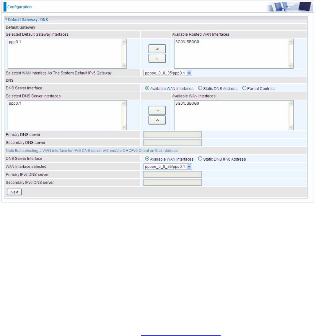
100
Click Next to continue to set the default gateway and DNS for IPv4 and IPv6.
Default Gateway
Select default gateway for you connection (IPv4 and IPv6).
DNS
¾ IPv4
Three ways to set an IPv4 DNS server
L Available WAN interfaces: Select a desirable WAN interface as the IPv4 DNS server.
L Static DNS Address: To specify DNS server manually by entering your primary and
secondary DNS server addresses.
L Parent Controls: If user registers and gets a DNS account in the parental control provider
website, expecting to enjoy a more reliable and safer internet surfing environment, please
select this option (need to configure at Parental Control Provider).
¾ IPv6
Obtain IPv6 DNS info from a WAN interface
WAN Interface selected: Select one configured IPv6 WAN connection from the menu to be as an
IPv6 DNS.
Static DNS IPv6 Address
Primary IPv6 DNS Server / Secondary IPv6 DNS Server: Type the specific primary and secondary
IPv6 DNS Server address.
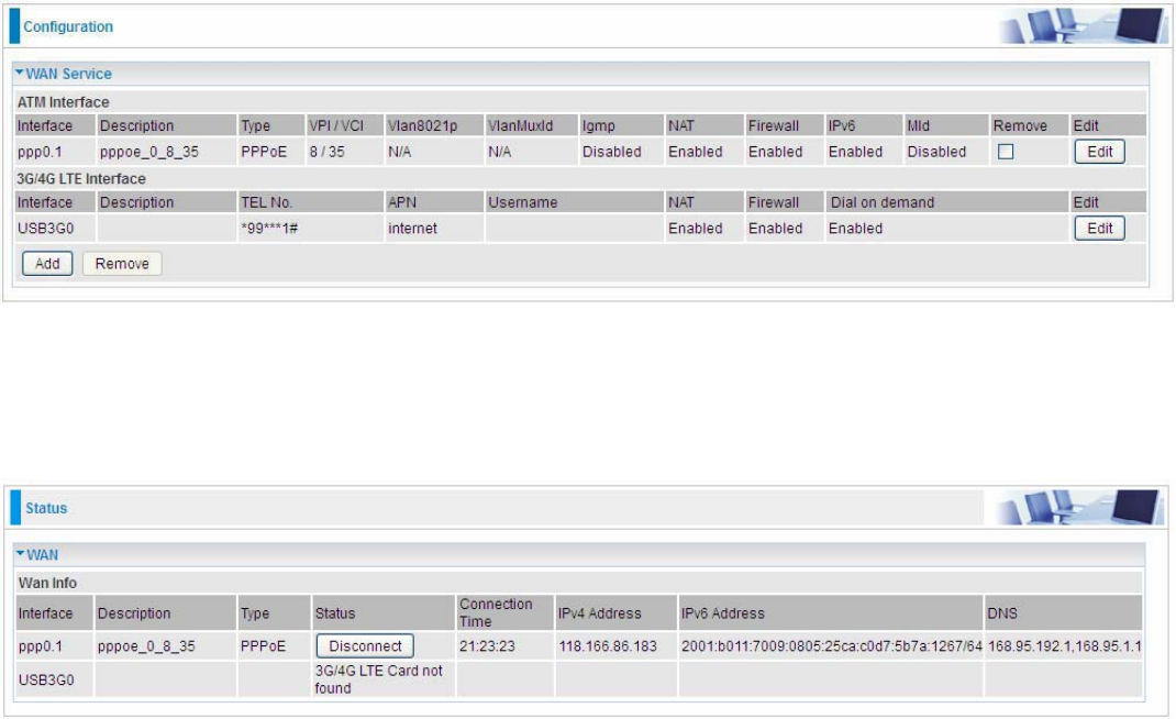
101
If you don’t need a service, select the item you want to remove, check the checkbox, then press
Remove.
Press Edit button to re-edit this service settings.
Here you can configure WAN Service, if it is OK, you can access the internet. You can go to Status
>WAN or Summary to view the WAN connection information (if your ISP provides IPv6 service, then
you will obtain an IPv6 address).
(IPv4 or IPv6)
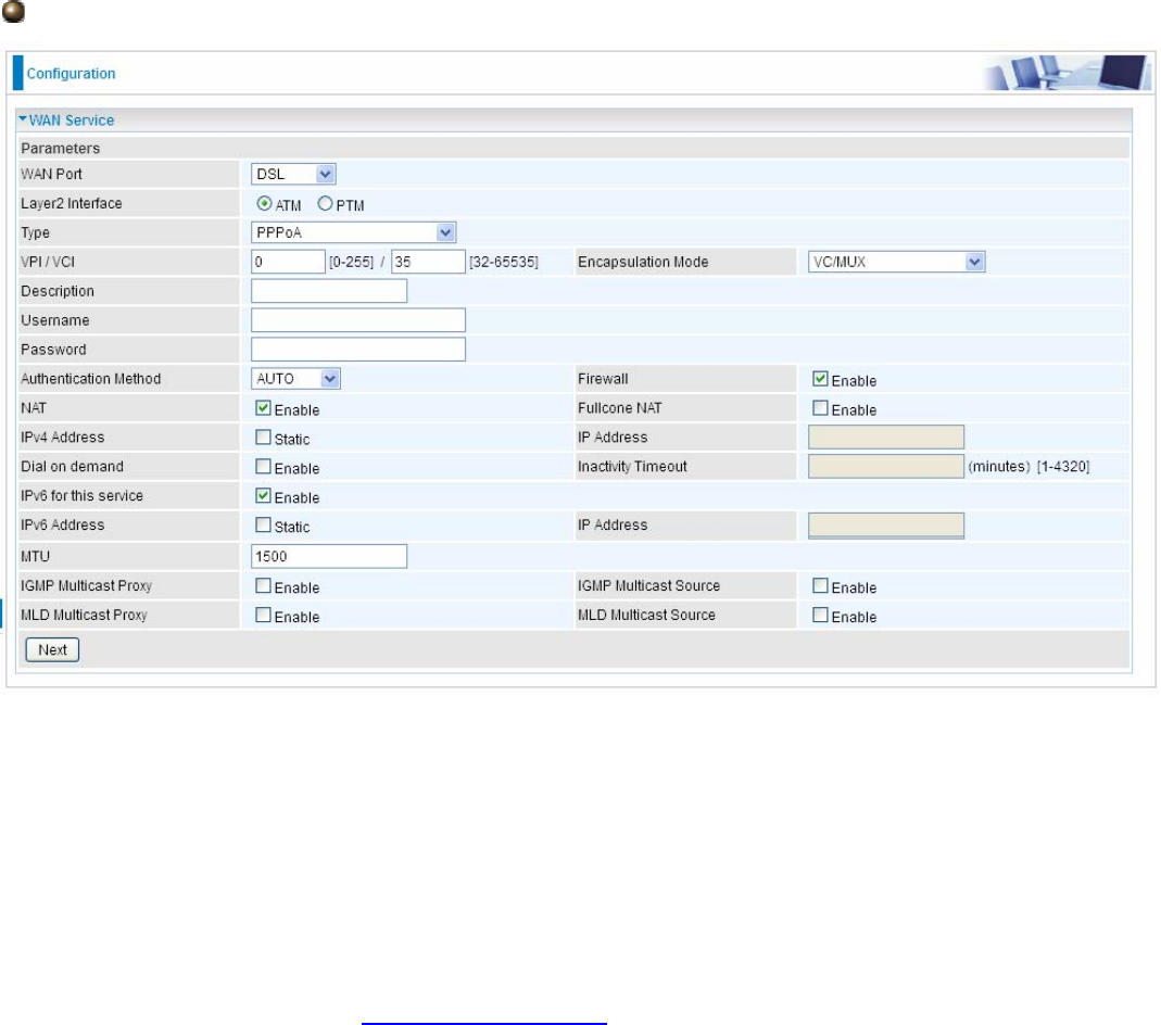
102
PPPoA
VPI/VCI: Enter the VPI/VCI combination from you ISP.
Encapsulation Mode: Select the encapsulation mode, LLC/SNAP-BRIDGING, or VC/MUX.
Description: User-defined description for the connection.
Username: Enter the account obtained from the ISP.
Password: Enter the password obtained from the ISP.
Authentication Method: Default is Auto. Or else your ISP will advise you the appropriate mode.
Firewall: Enable to drop all traffic from WAN side. If enabled, all incoming packets by default would
be dropped, and please turn to IP Filtering Incoming to add allowing rules.
NAT: The NAT (Network Address Translation) feature allows multiple users to access the Internet
through a single IP account by sharing the single IP address. If users on your LAN have their own
public IP addresses to access the Internet, NAT function can be disabled. When enabled, a Fullcone
NAT parameter will appear, you can determine whether to enable Fullcone NAT. While only NAT
enabled, the default NAT type Port-Restricted cone NAT will be used.
Fullcone NAT: Enable or disable fullcone NAT. Fullcone is a kind of NAT, in this mode, all requests
from the same internal IP address and port are mapped to the same external IP address and port.
Furthermore, any external host can send a packet to the internal host, by sending a packet to the
mapped external address.
Note: In this connection, NAT is enabled by default, you can determine whether to enable Fullcone
NAT or disable Fullcone NAT and only use NAT, the default NAT type is Port Restricted cone NAT.
With Port-Restricted cone NAT, the restriction includes port numbers. Specifically, an external host
can send a packet, with source IP address X and source port P, to the internal host only if the
internal host had previously sent a packet to IP address X and port P
IPv4 Address: Select whether to set static IPv4 address or obtain automatically.
IP Address: If Static is enabled in the above field, enter the static IPv4 address get from the ISP.
Dial on demand: It is a parameter to let users to dial for connection to internet themselves. It is
103
useful when saving internet fees.
Inactivity Timeout: The set Inactivity timeout period, unit: minutes. It is combined use with Dial on
Demand, users should specify the concrete time interval for dial on demand.
IPv6 for this service: Enable to use IPv6 service.
IPv6 Address: Select whether to set static IPv6 address or obtain automatically.
IP Address: If Static is enabled in the above field, enter the static IPv4 address.
MTU: Maximum Transmission Unit, the size of the largest datagram (excluding media-specific
headers) that IP will attempt to send through the interface.
IGMP Multicast Proxy: Check whether to enable this feature. IGMP (Internet Group Management
Protocol) Proxy intercepts the IGMP request from Clients and set up the multicast-forwarding table,
it takes over some of the router’s job, simplifying the router’s job and multicast communication.
IGMP Multicast Source: Enable to support the “source filtering” which is the ability for a system to
report interest in receiving packets “only ” from specific source address(es), or “all but” specific
source address(es), sent to a particular multicast address. Note: It works only on IGMP version 3.
MLD Multicast Proxy: check whether to enable this function. MLD (Multicast Listener Discovery
Protocol) Proxy intercepts the MLD request from Clients a set up the multicast-forwarding table. it
takes over some of the router’s job, simplifying the router’s job and multicast communication.
Support MLDv1 and MLDv2.
MLD Multicast Source: Used in a similar way by IPv6 system as IGMP Multicast source in IPv4
system. Enable it to support the source filtering functionality for IPv6 system. Note: It works only on
MLD version 2.
Click Next to continue to set the default gateway and DNS for IPv4 and IPv6.
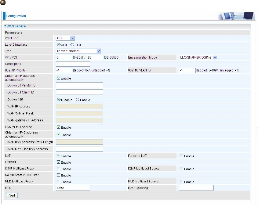
104
IP over Ethernet
VPI/VCI: Enter the VPI/VCI combination from you ISP.
Encapsulation Mode: Select the encapsulation mode, LLC/SNAP-BRIDGING, or VC/MUX.
Description: User-defined description for the connection, commonly for friendly use.
802.1P Priority: The parameter indicates the frame priority level from 0 (lowest) to 7 (highest), which
can be used to prioritize different classes of traffic (voice, video, data, etc). Enter the priority
identification, tagged: 0-1, untagged: -1.
802.1Q VLAN ID: It is a parameter to specify the VLAN which the frame belongs. Enter the VLAN ID
identification, tagged: 0-4094, untagged : -1.
Here two modes are supported for users to deal with the IP and DNS. You can select obtain
automatically or manually input the information according to your ISP.
Obtain an IP address automatically: Check whether to enable this function.
Option 60 Vendor ID: Enter the associated information by your ISP. This option is used by DHCP
clients to optionally identify the vendor type and configuration of a DHCP client. The information is a
string of n octets, interpreted by servers. Vendors may choose to define specific vendor class
identifiers to convey particular configuration or other identification information about a client.
Option 61 ClientID: Enter the associated information provided by your ISP.
Option 125: Option 125 is a complementary standard of DHCP protocol, it is used to encapsulate
option 125 message into DHCP offer packet before forward it to clients. After the clients receive the

105
packet, it check the option 125 field in the packet with the prestored message, if it is matched, then
the client accepts this offer, otherwise it will be abandoned. Check Enable or Disable this function.
Default setting is Disable.
WAN IP Address: Enter your IPv4 address to the device provided by your ISP.
WAN Subnet Mask: Enter your submask to the device provided by your ISP.
WAN gateway IP Address: Enter your gateway IP address to the device provided by your ISP.
IPv6 for this service: Enable to use IPv6 service.
Obtain an IPv6 address automatically: check whether to enable or disable this feature.
WAN IPv6 Address/Prefix Length: Enter the WAN IPv6 Address/Prefix Length from your ISP.
WAN Next-Hop IPv6 Address: Enter the WAN Next-Hop IPv6 Address from your ISP.
Note: If you don’t know well about the DHCP Option, you can leave it empty or leave it as default.
NAT: The NAT (Network Address Translation) feature allows multiple users to access the Internet
through a single IP account by sharing the single IP address. If users on your LAN have their own
public IP addresses to access the Internet, NAT function can be disabled. When enabled, a Fullcone
NAT parameter will appear, you can determine whether to enable Fullcone NAT. While only NAT
enabled, the default NAT type Port-Restricted cone NAT will be used.
Fullcone NAT: Enable or disable fullcone NAT. Fullcone is a kind of NAT, in this mode, all requests
from the same internal IP address and port are mapped to the same external IP address and port.
Furthermore, any external host can send a packet to the internal host, by sending a packet to the
mapped external address.
Firewall: Enable to drop all traffic from WAN side. If enabled, all incoming packets by default would
be dropped, and please turn to IP Filtering Incoming to add allowing rules.
IGMP Multicast Proxy: Check whether to enable this feature. IGMP (Internet Group Management
Protocol) Proxy intercepts the IGMP request from Clients and set up the multicast-forwarding table,
it takes over some of the router’s job, simplifying the router’s job and multicast communication.
IGMP Multicast Source: Enable to support the “source filtering” which is the ability for a system to
report interest in receiving packets “only ” from specific source address(es), or “all but” specific
source address(es), sent to a particular multicast address. Note: It works only on IGMP version 3.
No Multicast VLAN Filter: Enable to deactivate the multicast VLAN filter which allows users to filter
on all multicast packets or on specific multicast groups.
MLD Multicast Proxy: check whether to enable this function. MLD (Multicast Listener Discovery
Protocol) Proxy intercepts the MLD request from Clients a set up the multicast-forwarding table. it
takes over some of the router’s job, simplifying the router’s job and multicast communication.
Support MLDv1 and MLDv2. Note: It works only on MLD version 2.
MLD Multicast Source: Used in a similar way by IPv6 system as IGMP Multicast source in IPv4
system. Enable it to support the source filtering functionality for IPv6 system.
MTU: Maximum Transmission Unit, the size of the largest datagram (excluding media-specific
headers) that IP will attempt to send through the interface.
MAC Spoofing: This option is required by some service providers specifying some specific MAC
allowed for joining network. You must fill in the MAC address specified by your service provider
when this information is required.
Click Next to continue to set the default gateway and DNS for IPv4 and IPv6.
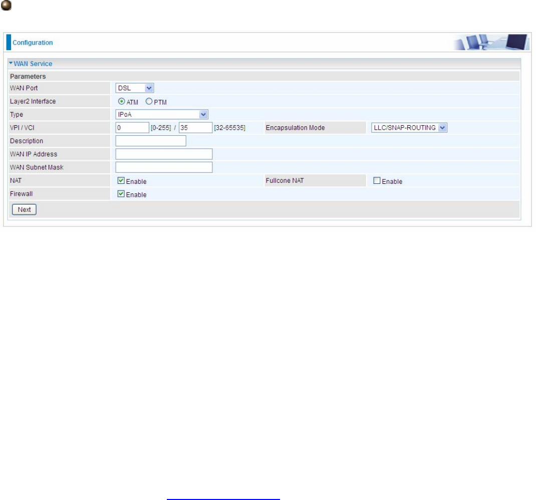
106
IPoA
VPI/VCI: Enter the VPI/VCI combination from you ISP.
Encapsulation Mode: Select the encapsulation mode, LLC/SNAP-BRIDGING, or VC/MUX.
Description: User-defined description for the connection, commonly for friendly use.
WAN IP Address: Enter the WAN IP from the ISP.
WAN Subnet Mask: Enter the WAN Subnet Mask from the ISP.
NAT: The NAT (Network Address Translation) feature allows multiple users to access the Internet
through a single IP account by sharing the single IP address. If users on your LAN have their own
public IP addresses to access the Internet, NAT function can be disabled. When enabled, a Fullcone
NAT parameter will appear, you can determine whether to enable Fullcone NAT. While only NAT
enabled, the default NAT type Port-Restricted cone NAT will be used.
Fullcone NAT: Enable or disable fullcone NAT. Fullcone is a kind of NAT, in this mode, all requests
from the same internal IP address and port are mapped to the same external IP address and port.
Furthermore, any external host can send a packet to the internal host, by sending a packet to the
mapped external address.
Firewall: Enable to drop all traffic from WAN side. If enabled, all incoming packets by default would
be dropped, and please turn to IP Filtering Incoming to add allowing rules.
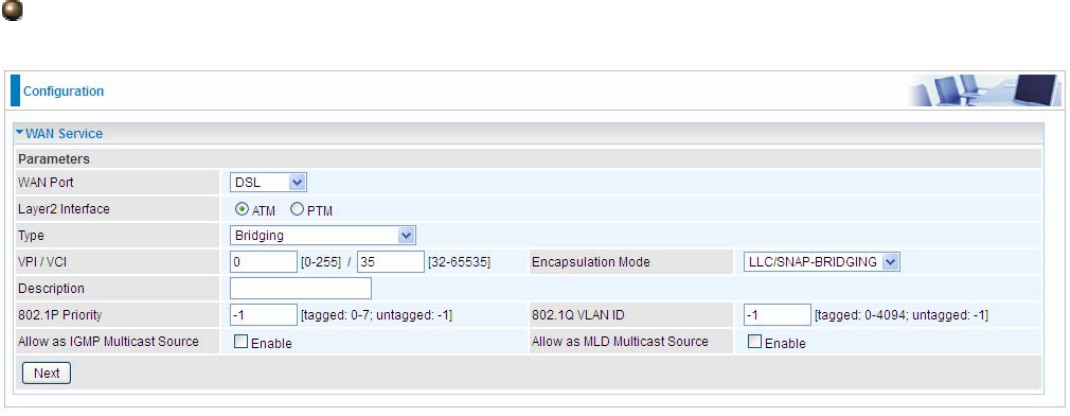
107
Bridging
VPI/VCI: Enter the VPI/VCI combination from you ISP.
Encapsulation Mode: Select the encapsulation mode, LLC/SNAP-BRIDGING, or VC/MUX.
Description: User-defined description for the connection, commonly for friendly use.
802.1P Priority: The parameter indicates the frame priority level from 0 (lowest) to 7 (highest), which
can be used to prioritize different classes of traffic (voice, video, data, etc). Enter the priority
identification, tagged: 0-1, untagged: -1.
802.1Q VLAN ID: It is a parameter to specify the VLAN which the frame belongs. Enter the VLAN ID
identification, tagged: 0-4094, untagged : -1.
Allow as IGMP Multicast Source: Enable to support the “source filtering” which is the ability for a
system to report interest in receiving packets “only ” from specific source address(es), or “all but”
specific source address(es), sent to a particular multicast address. Note: It works only on IGMP
version 3.
Allow as MLD Multicast Source: Used in a similar way by IPv6 system as IGMP Multicast source
in IPv4 system. Enable it to support the source filtering functionality for IPv6 system. Note: It works
only on MLD version 2.
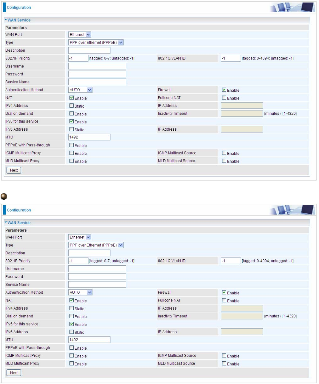
108
L Ethernet
Ethernet WAN connection is well known as directly broadband WAN connection.
PPPoE
Description: User-defined description for the connection, commonly for friendly use.
802.1P Priority: The parameter indicates the frame priority level from 0 (lowest) to 7 (highest), which
can be used to prioritize different classes of traffic (voice, video, data, etc). Enter the priority
identification, tagged: 0-1, untagged: -1.
802.1Q VLAN ID: It is a parameter to specify the VLAN which the frame belongs. Enter the VLAN ID

109
identification, tagged: 0-4094, untagged : -1.
Username: Enter the account obtained from the ISP.
Password: Enter the password obtained from the ISP.
Service Name: The item is for identification purpose, user can define it yourselfe.
Authentication Method: Default is Auto. Or else your ISP will advise you the appropriate mode.
Firewall: Enable to drop all traffic from WAN side. If enabled, all incoming packets by default would
be dropped, and please turn to IP Filtering Incoming to add allowing rules.
NAT: The NAT (Network Address Translation) feature allows multiple users to access the Internet
through a single IP account by sharing the single IP address. If users on your LAN have their own
public IP addresses to access the Internet, NAT function can be disabled. When enabled, a Fullcone
NAT parameter will appear, you can determine whether to enable Fullcone NAT. While only NAT
enabled, the default NAT type Port-Restricted cone NAT will be used.
Fullcone NAT: Enable or disable fullcone NAT. Fullcone is a kind of NAT, in this mode, all requests
from the same internal IP address and port are mapped to the same external IP address and port.
Furthermore, any external host can send a packet to the internal host, by sending a packet to the
mapped external address.
Note: In PPPoE connection, NAT is enabled by default, you can determine whether to enable
Fullcone NAT. and while you disable Fullcone NAT and only use NAT, the default NAT type is Port
Restricted or Port-Restricted cone NAT, the restriction includes port numbers. Specifically, an
external host can send a packet, with source IP address X and source port P, to the internal host
only if the internal host had previously sent a packet to IP address X and port P.
IPv4 Address: Select whether to set static IPv4 address or obtain automatically.
IP Address: If Static is enabled in the above field, enter the static IPv4 address get from the ISP.
Dial on demand: It is a parameter to let users to dial for connection to internet themselves. It is
useful when saving internet fees.
Inactivity Timeout: The set Inactivity timeout period, unit: minutes. It is combined use with Dial on
Demand, users should specify the concrete time interval for dial on demand.
IPv6 for this service: Enable to use IPv6 service.
IPv6 Address: Select whether to set static IPv6 address or obtain automatically.
IP Address: If Static is enabled in the above field, enter the static IPv4 address.
MTU: Maximum Transmission Unit, the size of the largest datagram (excluding media-specific
headers) that IP will attempt to send through the interface.
PPPoE with Pass-through: Enable or disable PPPoE pass-through. If it is enabled, PCs behind the
router can dial itself.
IGMP Multicast Proxy: Check whether to enable this feature. IGMP (Internet Group Management
Protocol) Proxy intercepts the IGMP request from Clients and set up the multicast-forwarding table,
it takes over some of the router’s job, simplifying the router’s job and multicast communication.
IGMP Multicast Source: Enable to support the “source filtering” which is the ability for a system to
report interest in receiving packets “only ” from specific source address(es), or “all but” specific
source address(es), sent to a particular multicast address. Note: It works only on IGMP version 3.
MLD Multicast Proxy: check whether to enable this function. MLD (Multicast Listener Discovery
Protocol) Proxy intercepts the MLD request from Clients a set up the multicast-forwarding table. it
takes over some of the router’s job, simplifying the router’s job and multicast communication.
Support MLDv1 and MLDv2.
MLD Multicast Source: Used in a similar way by IPv6 system as IGMP Multicast source in IPv4
system. Enable it to support the source filtering functionality for IPv6 system. Note: It works only on
MLD version 2.
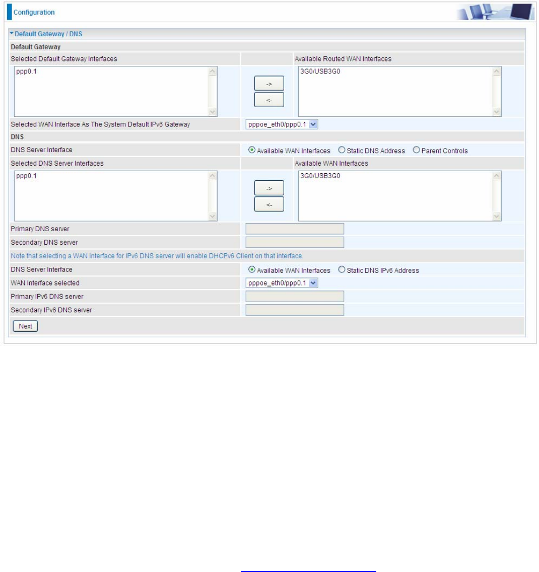
110
Click Next to continue to set the default gateway and DNS for IPv4 and IPv6.
Default Gateway
Select default gateway for you connection (IPv4 and IPv6).
DNS
¾ IPv4
Three ways to set an IPv4 DNS server
L Available WAN interfaces: Select a desirable WAN interface as the IPv4 DNS server.
L Static DNS Address: To specify DNS server manually by entering your primary and
secondary DNS server addresses.
L Parent Controls: If user registers and gets a DNS account in the parental control provider
website, expecting to enjoy a more reliable and safer internet surfing environment, please
select this option (need to configure at Parental Control Provider).
¾ IPv6
Obtain IPv6 DNS info from a WAN interface
WAN Interface selected: Select one configured IPv6 WAN connection from the menu to be as an
IPv6 DNS.
Static DNS IPv6 Address
Primary IPv6 DNS Server / Secondary IPv6 DNS Server: Type the specific primary and secondary
IPv6 DNS Server address.
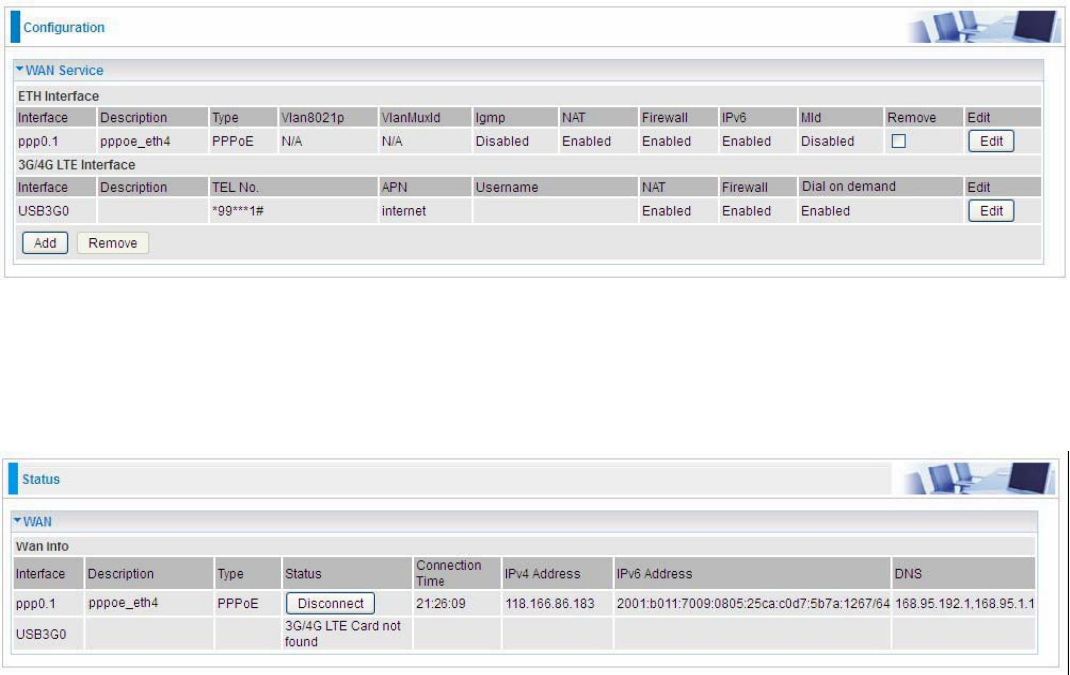
111
If you don’t need the service, select the item you want to remove, check the checkbox, then press
Remove, it will be OK.
Press Edit button to re-edit this service settings.
Here the corresponding WAN Service have been configured, if it is OK, you can access the internet.
You can go to Status>WAN or Summary to view the WAN connection information (if your ISP
provides IPv6 service, then you will obtain an IPv6 address).
(IPv4 or IPv6)
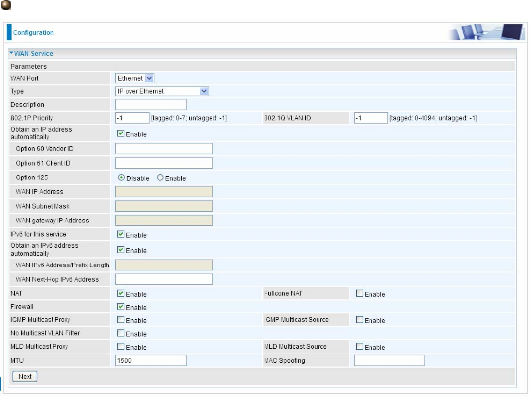
112
IP over Ethernet
Description: User-defined description for the connection, commonly for friendly use.
802.1P Priority: The parameter indicates the frame priority level from 0 (lowest) to 7 (highest), which
can be used to prioritize different classes of traffic (voice, video, data, etc). Enter the priority
identification, tagged: 0-1, untagged: -1.
802.1Q VLAN ID: It is a parameter to specify the VLAN which the frame belongs. Enter the VLAN ID
identification, tagged: 0-4094, untagged : -1.
Here two modes are supported for users to deal with the IP and DNS. You can select obtain
automatically or manually input the information according to your ISP.
Obtain an IP address automatically: Check whether to enable this function.
Option 60 Vendor ID: Enter the associated information by your ISP. This option is used by DHCP
clients to optionally identify the vendor type and configuration of a DHCP client. The information is a
string of n octets, interpreted by servers. Vendors may choose to define specific vendor class
identifiers to convey particular configuration or other identification information about a client.
Option 61 ClientID: Enter the associated information provided by your ISP.
Option 125: Option 125 is a complementary standard of DHCP protocol, it is used to encapsulate
option 125 message into DHCP offer packet before forward it to clients. After the clients receive the
packet, it check the option 125 field in the packet with the pre-stored message, if it is matched, then
the client accepts this offer, otherwise it will be abandoned. Check Enable or Disable this function.
Default setting is Disable.
WAN IP Address: Enter your IPv4 address to the device provided by your ISP.
WAN Subnet Mask: Enter your submask to the device provided by your ISP.

113
WAN gateway IP Address: Enter your gateway IP address to the device provided by your ISP.
IPv6 for this service: Enable to use IPv6 service.
Obtain an IPv6 address automatically: check whether to enable or disable this feature.
WAN IPv6 Address/Prefix Length: Enter the WAN IPv6 Address/Prefix Length from your ISP.
WAN Next-Hop IPv6 Address: Enter the WAN Next-Hop IPv6 Address from your ISP.
Note: If you don’t know well about the DHCP Option, you can leave it empty or leave it as default.
NAT: The NAT (Network Address Translation) feature allows multiple users to access the Internet
through a single IP account by sharing the single IP address. If users on your LAN have their own
public IP addresses to access the Internet, NAT function can be disabled. When enabled, a Fullcone
NAT parameter will appear, you can determine whether to enable Fullcone NAT. While only NAT
enabled, the default NAT type Port-Restricted cone NAT will be used.
Fullcone NAT: Enable or disable fullcone NAT. Fullcone is a kind of NAT, in this mode, all requests
from the same internal IP address and port are mapped to the same external IP address and port.
Furthermore, any external host can send a packet to the internal host, by sending a packet to the
mapped external address.
Firewall: Enable to drop all traffic from WAN side. If enabled, all incoming packets by default would
be dropped, and please turn to IP Filtering Incoming to add allowing rules.
IGMP Multicast Proxy: IGMP (Internet Group Membership Protocol) is a protocol used by IP
hosts to report their multicast group memberships to any immediately neighboring multicast routers.
Check this item to enable IGMP multicast on that WAN interface for multicast forwarding.
IGMP Multicast Source: Enable to support the “source filtering” which is the ability for a system to
report interest in receiving packets “only ” from specific source address(es), or “all but” specific
source address(es), sent to a particular multicast address. Note: It works only on IGMP version 3.
No Multicast VLAN Filter: Enable to deactivate the multicast VLAN filter which allows users to filter
on all multicast packets or on specific multicast groups.
MLD Multicast Proxy: check whether to enable this function. MLD (Multicast Listener Discovery
Protocol) Proxy intercepts the MLD request from Clients a set up the multicast-forwarding table. it
takes over some of the router’s job, simplifying the router’s job and multicast communication.
Support MLDv1 and MLDv2.
MLD Multicast Source: Used in a similar way by IPv6 system as IGMP Multicast source in IPv4
system. Enable it to support the source filtering functionality for IPv6 system. Note: It works only on
MLD version 2.
MTU: Maximum Transmission Unit, the size of the largest datagram (excluding media-specific
headers) that IP will attempt to send through the interface.
MAC Spoofing: This option is required by some service providers specifying some specific MAC
allowed to join in network. You must fill in the MAC address specified by your service provider when
this information is required.
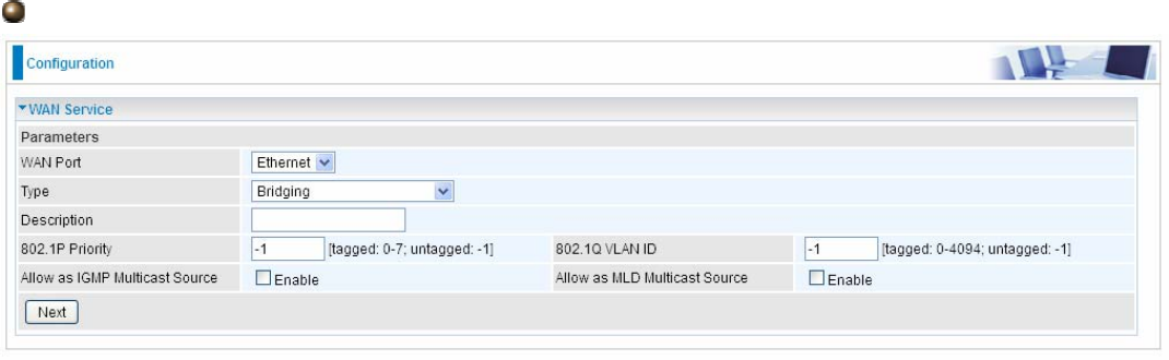
114
Bridging
Description: User-defined description for the connection, commonly for friendly use.
802.1P Priority: The parameter indicates the frame priority level from 0 (lowest) to 7 (highest), which
can be used to prioritize different classes of traffic (voice, video, data, etc). Enter the priority
identification, tagged: 0-1, untagged: -1.
802.1Q VLAN ID: It is a parameter to specify the VLAN which the frame belongs. Enter the VLAN ID
identification, tagged: 0-4094, untagged : -1.
Allow as IGMP Multicast Source: Enable to support the “source filtering” which is the ability for a
system to report interest in receiving packets “only ” from specific source address(es), or “all but”
specific source address(es), sent to a particular multicast address. Note: It works only on IGMP
version 3.
Allow as MLD Multicast Source: Used in a similar way by IPv6 system as IGMP Multicast source
in IPv4 system. Enable it to support the source filtering functionality for IPv6 system. Note: It works
only on MLD version 2.
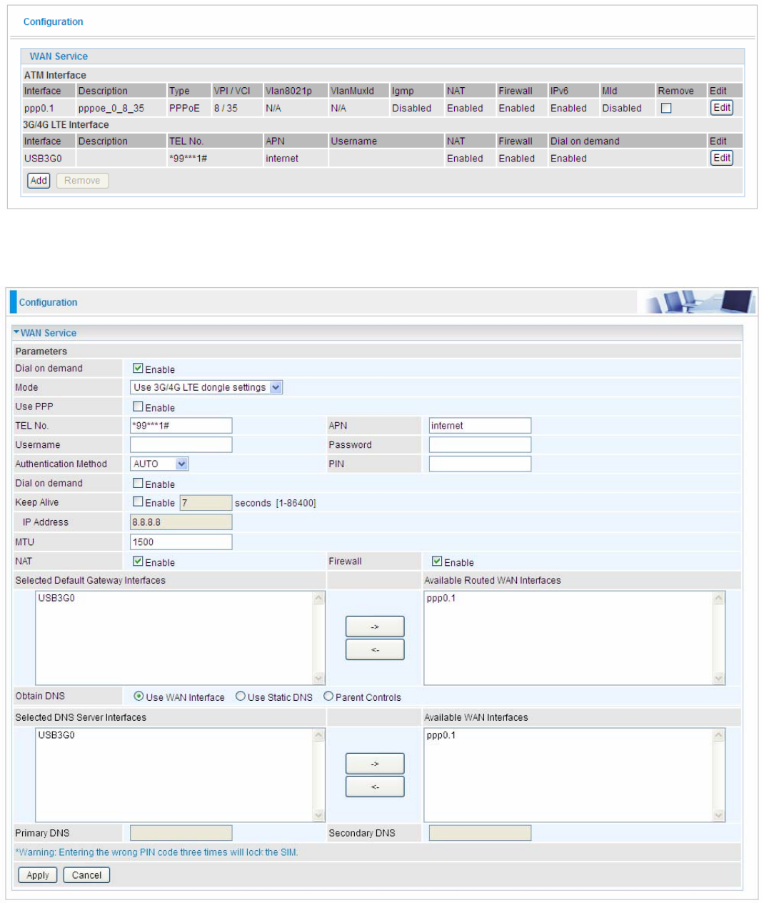
115
L 3G/4G LTE
Select 3G/4G LTE to configure the route to enjoy the mobility. By default the 3G/4G LTE interface is
on, user can edit the parameters to meet your own requirements.
Click Edit button to enter the 3G/4G LTE configuration page.
Dial on demand: If enabled, the 3G/LTE will work in dial on demand and be brought up only when
there is no active default route. In this mode, 3G/4G LTE work as a backup for the WAN connectivity.
While if disabled, 3G/4G LTE serves as a normal interface, and can only be brought up when it has
been configured to achieve a mobile connectivity.
Mode: There are 6 options of phone service standards: GSM 2G only, UTMS 3G only, GSM 2G
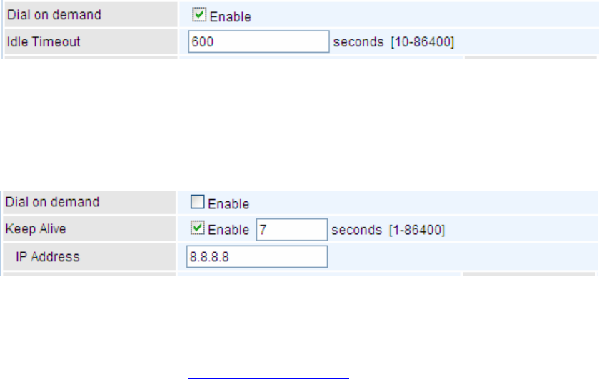
116
preferred, UMTS 3G preferred, Automatic, and Use 3G/4G LTE dongle settings. If you are uncertain
what services are available to you, and then please select Automatic.
TEL No.: The dial string to make a 3G/4G LTE user internetworking call. It may provide by your
mobile service provider.
APN: An APN is similar to a URL on the WWW, it is what the unit makes a GPRS / UMTS call. The
service provider is able to attach anything to an APN to create a data connection, requirements for
APNs varies between different service providers. Most service providers have an internet portal
which they use to connect to a DHCP Server, thus giving you access to the internet i.e. some 3G
operators use the APN ‘internet’ for their portal. The default value is “internet”.
Username/Password: Enter the username and password provided by your service provider. The
username and password are case sensitive.
Authentication Method: Default is Auto. Please consult your service provider on whether to use
PAP, CHAP or MSCHAP.
PIN: PIN stands for Personal Identification Number. A PIN code is a numeric value used in certain
systems as a password to gain access, and authenticate. In mobile phones a PIN code locks the
SIM card until you enter the correct code. If you enter the PIN code incorrectly into the phone 3 times
in a row, then the SIM card will be blocked and you will require a PUK code from your network/
service provider.
L Dial on Demand: If you want to make UMTS/GPRS call only when there is a packet
requesting access to the Internet (i.e. when a program on your computer attempts to access
the Internet). In this mode, you must set Idle Timeout value at same time. Click on Connect on
Demand, the Idle Timeout field will display.
Idle Timeout: Auto-disconnect the broadband firewall gateway when there is no activity on
the line for a predetermined period of time. Default is 600 seconds.
L Keep Alive: Check Enable to allow the router to send message out every 7 seconds (can be
changed base on need) to prevent the connection being dropped by ISP.
IP Address: The IP address is used to “ping”, and router will ping the IP to find whether the
connection is still on.
NAT: Check to enable the NAT function.
Firewall: Enable to drop all traffic from WAN side. If enabled, all incoming packets by default would
be dropped, and please turn to IP Filtering Incoming to add allowing rules.
MTU: MTU (Maximum Transmission Unit) is the size of the largest datagram that IP will attempt to
send through the interface.
Select default gateway interfaces: Select from the interfaces the default gateway, here commonly
we select USB3G0.
Selected DNS Server Interfaces: Three ways to set a DNS server.
L Use WAN interface: Select a desirable WAN interface as the DNS server.
L Use Static DNS: To specify DNS server manually by entering your primary and secondary
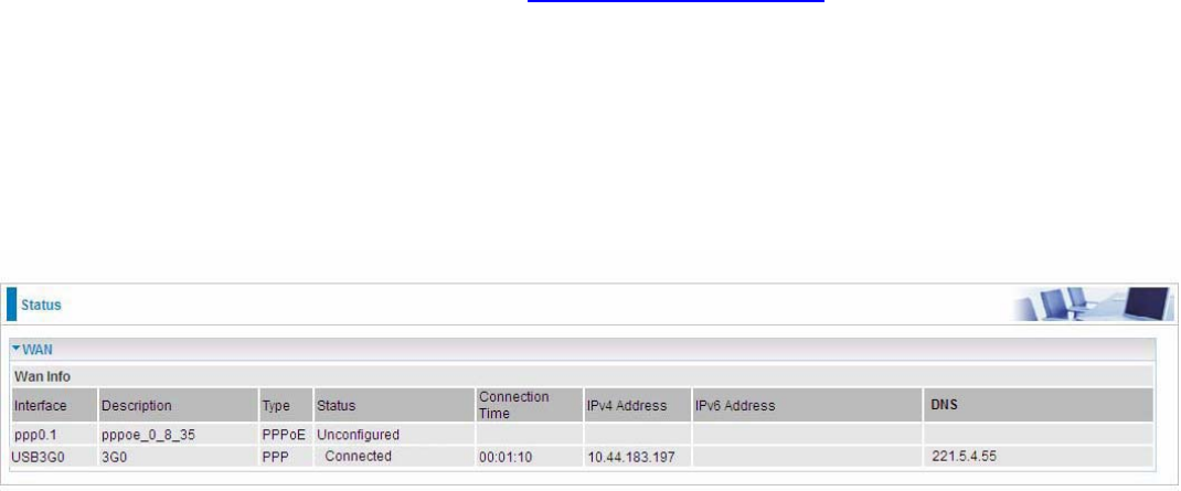
117
DNS server addresses.
L Parent Controls: If user registers and gets a DNS account in the parental control provider
website, expecting to enjoy a more reliable and safer internet surfing environment, please
select this option (need to configure at Parental Control Provider).
Click Apply to confirm the settings.
Here you can configure WAN Service, if it is OK, you can access the internet. You can go to Status
>WAN or Summary to view the WAN connection information.
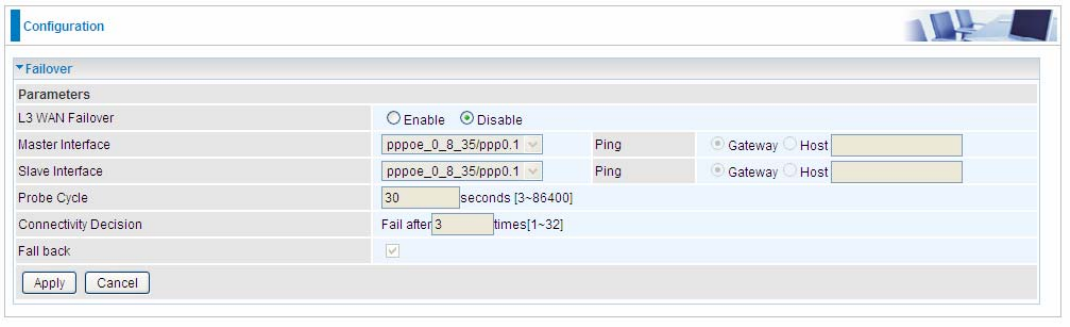
118
Failover
Auto failover/failback is to ensure an always-on internet connection. Users can set a Master WAN
interface (main WAN) and a slave interface (backup WAN), and when Master WAN fails, it will switch
to slave WAN, and when master WAN restores, it will switch to master WAN interface again.
L3 WAN Failover: Check Enable to activate L3 WAN failover.
Master Interface: Select a master WAN interface.
Ping: To ping to check the master WAN interface’s connectivity.
L Gateway: It will send ping packets to gateway of master interface and wait for response from
it in every “Probe Cycle” to check the connectivity of the gateway of master interface.
L Host: It will send ping packets to specific host and wait for response in every “Probe Cycle”.
Slave Interface: Select a slave WAN interface as backup port.
Ping: To ping to check the slave WAN inteface’s connectivity.
L Gateway: It will send ping packets to gateway of slave interface and wait for response from it
in every “Probe Cycle” to check the connectivity of the gateway of slave interface.
L Host: It will send ping packets to specific host and wait for response in every “Probe Cycle”.
Probe Cycle: Set the time duration for the Probe Cycle to determine when the router will switch to
the backup connection once the main connection (main port) fails. For example, when set to 30
seconds, the probe will be conducted every 30 seconds.
Connectivity Decision: Set how many times of probing failure to switch to backup port.
Fallback: Enable to reconnect to the master interface when master interface connection recovers.
Note:
1) The time set is for each probe cycle, but the decision to change to the backup port is determined
by Probe Cycle multiplied by connection Decision amount (e.g. From the image above it will be
30 seconds multiplied by 3 consecutive fails, the router will determine failover to slave interface.
2).The failback setting follow the same decision policy as the failover. For example, according to
settings above in the screenshot, the connection probe will be carried out every 30 seconds, and 3
consecutive times of probe success is found, the router will determine failback to master interface.
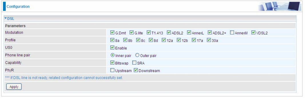
119
DSL
This screen allows you to set DSL parameters. DSL knowledge is required to configure these
settings. Contact your ISP to make sure that these parameters are correct.
Modulation: There are 8 modes “G.Dmt”, “G.lite”, “T1.413”, “ADSL2”, “AnnexL”, ”ADSL2+”,
“AnnexM”, that user can select for this connection.
Profile: VDSL profiles up to 30a.
US0: Select to enable US0. In VDSL mode, profiles like 8a, 8b, 8c, 8d and 12a need users to enable
US0 band.
Phone line pair: This is for reserved only. You can choose "Inner Pair" or "Outer Pair".
Capability: There are 2 options “Bitswap Enable” and “SRA Enable” that user can select for this
connection.
L Bitswap Enable: Allows bitswaping function.
L SRA Enable: Allows seamless rate adaptation.
PhyR: A new technology to control impulse and noise to improve the BER and DSL data quality.
Click Apply to confirm the settings.
.
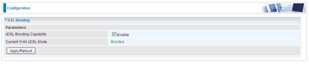
120
DSL Bonding
This feature allows you to double your VDSL2/ADSL2+ data rate. Contact your ISP to see if you can
upgrade your Internet service in order to use this feature.
xDSL Bonding Capability: To enable or disable the Dual VDSL2/ADSL2+ feature.
L Enable: The device will attempt to make connection in two-pair VDSL2/ADSL2+ mode.
L Disable: The device will only make a connection in single-pair VDSL2/ADSL2+ mode.
Current WAN xDSL Mode: This displays your current VDSL2/ADSL2+ connection mode on the
DSLAM/ISP. two-pair VDSL2/ADSL2+ or single-pair VDSL2/ADSL2+ is available.
Click Apply/Reboot to save settings then reboot the system to activate the changes.
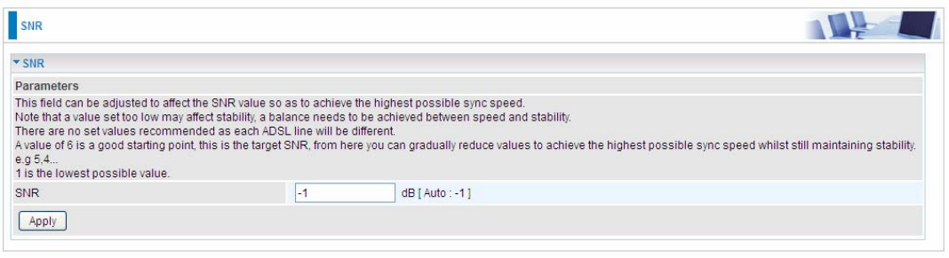
121
SNR
Signal-to-noise ratio (often abbreviated SNR or S/N) is a measure used in science and engineering
that compares the level of a desired signal to the level of background noise. It is defined as the ratio
of signal power to the noise power.
SNR: Change the value to adjust the DSL link rate, more suitable for an advanced user.