Billion Electric BIL-8920NX600 Dual-lines VDSL2/ADSL2+ Wireless-N 600Mbps 3G/4G LTE VPN Firewall Router User Manual 3
Billion Electric Co., Ltd. Dual-lines VDSL2/ADSL2+ Wireless-N 600Mbps 3G/4G LTE VPN Firewall Router Users Manual 3
Contents
- 1. Users Manual-1
- 2. Users Manual-2
- 3. Users Manual-3
Users Manual-3
224
DNS
DNS, Domain Name System, is a distributed database of TCP/IP application. DNS provides
translation of Domain name to IP.
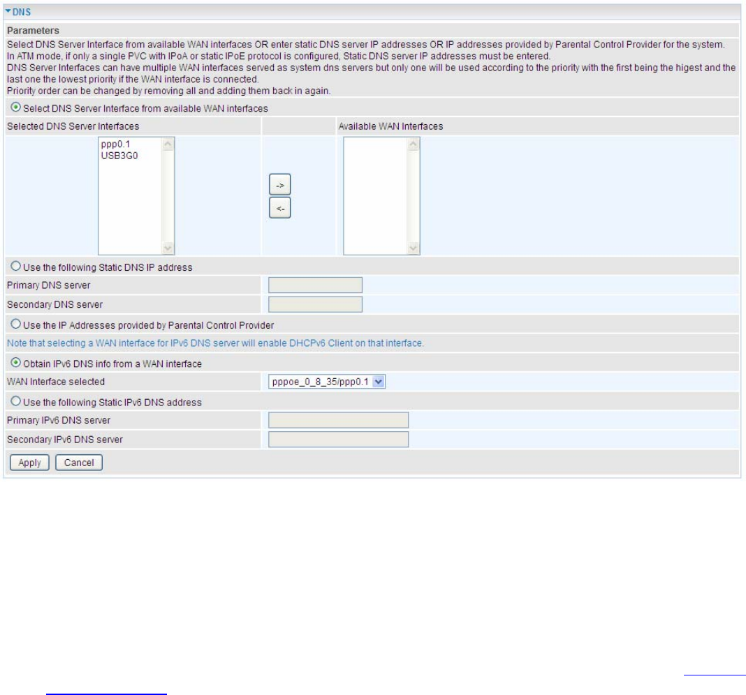
DNS
¾ IPv4
Three ways to set an IPv4 DNS server
L Select DNS server interface from available WAN interfaces: Select a desirable WAN
interface as the IPv4 DNS server.
L User the following Static DNS IP address: To specify DNS server manually by entering your
primary and secondary DNS server addresses.
L Use the IP address provided by Parental Control Provider: If user registers and gets an
DNS account in the parental control provider website, expecting to enjoy a more reliable and
safer internet surfing environment, please select this option (need to configure at Parental
Control Provider).
¾ IPv6:
IPv6 DNS Server’s operation is similar to IPv4 DNS server. There are two modes to get DNS server
address: Auto and Static mode.
Obtain IPv6 DNS info from a WAN interface
WAN Interface selected: Select one configured IPv6 WAN connection from the drop-down menu to
be as an IPv6 DNS.
Use the following Static IPv6 DNS address
225
Primary IPv6 DNS Server / Secondary IPv6 DNS Server: Type the specific primary and secondary
IPv6 DNS Server address.
226
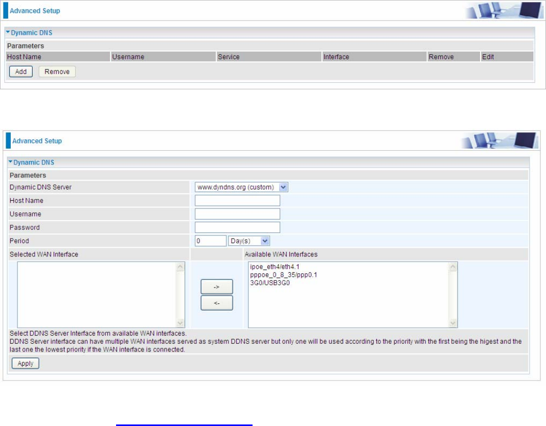
Dynamic DNS
The Dynamic DNS function allows you to alias a dynamic IP address to a static hostname, allowing
users whose ISP does not assign them a static IP address to use a domain name. This is especially
useful for hosting servers via your ADSL connection, so that anyone wishing to connect to you may
use your domain name, rather than having to use your dynamic IP address, which changes from
time to time. This dynamic IP address is the WAN IP address of the router, which is assigned to you
by your ISP.
Here users can register different WAN interfaces with different DNS(es).
Click Add to register a WAN interface with the exact DNS.
You will first need to register and establish an account with the Dynamic DNS provider using their
website, for example http://www.dyndns.org/
Dynamic DNS Server: Select the DDNS service you have established an account with.
Host Name, Username and Password: Enter your registered domain name and your username
and password for this service.
Period: Set the time period between updates, for the Router to exchange information with the DDNS
server. In addition to updating periodically as per your settings, the router will perform an update
when your dynamic IP address changes.
Selected WAN Interface: Select the Interface that is bound to the registered Domain name.
227
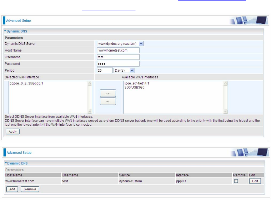
User can register different DDNS to different interfaces.
Examples: Note first users have to go to the Dynamic DNS registration service provider to register
an account.
User test register two Dynamic Domain Names in DDNS provider http://www.dyndns.org/ .
1. pppoe_0_8_35 with DDNS: www.hometest.com using username/password test/test
228
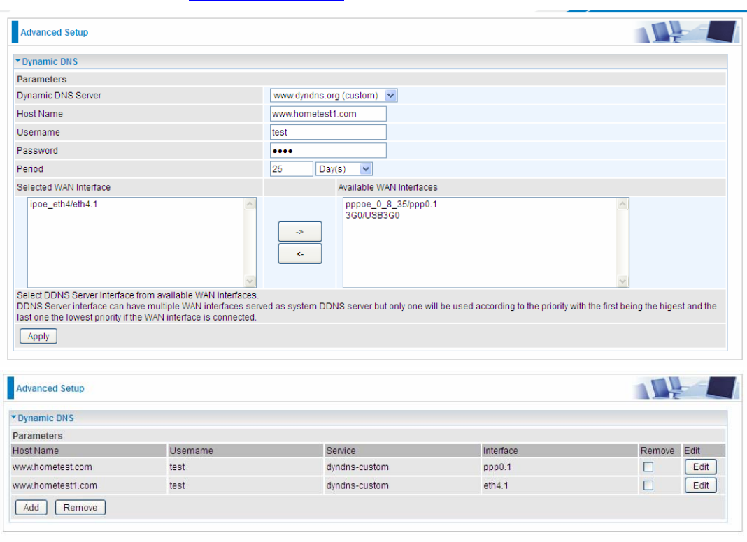
2. ipoe_eth4 with DDNS: www.hometest1.com using username/password test/test.
229
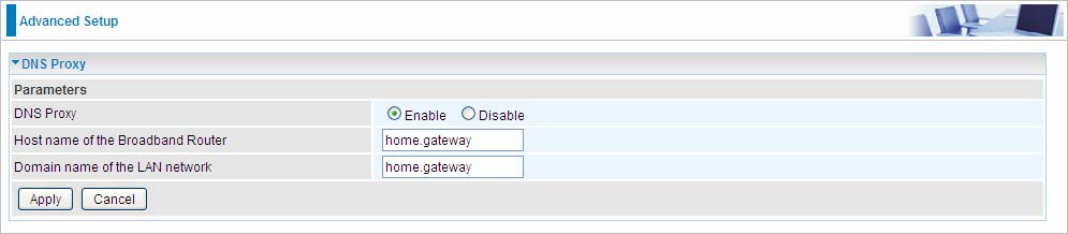
DNS Proxy
DNS proxy is used to forward request and response message between DNS Client and DNS Server.
Hosts in LAN can use router serving as a DNS proxy to connect to the DNS Server in public to
correctly resolve Domain name to access the internet.
DNS Proxy: Select whether to enable or disable DNS Proxy function, default is enabled.
Host name of the Broadband Router: Enter the host name of the router. Default is home.gateway.
Domain name of the LAN network: Enter the domain name of the LAN network. home.gateway.
230
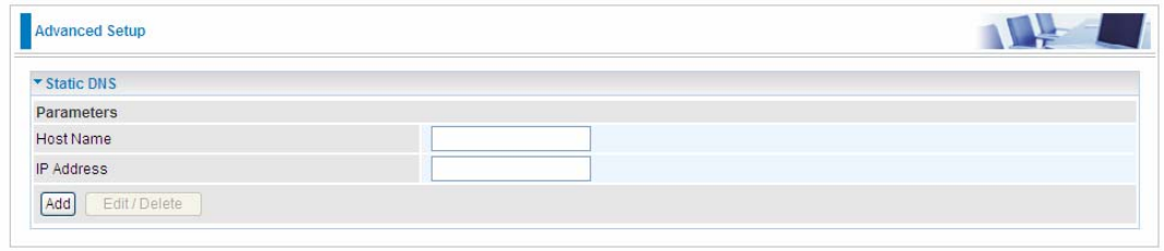
Static DNS
Static DNS is a concept relative to Dynamic DNS; in static DNS system, the IP mapped is static
without change.
You can map the specific IP to a user-friendly domain name. In LAN, you can map a PC to a domain
name for convenient access. Or you can set some well-known Internet IP mapping item so your
router will response quickly for your DNS query instead of querying from the ISP’s DNS server.
Host Name: Type the domain name (host name) for the specific IP .
IP Address: Type the IP address bound to the set host name above.
Click Add to save your settings.
231
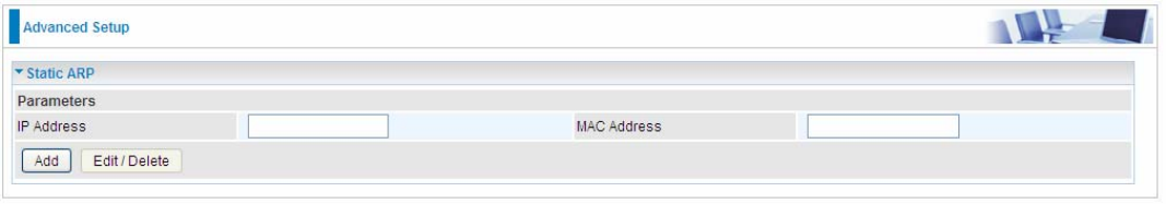
Static ARP
ARP (Address Resolution Protocol) is a TCP/IP protocol that allows the resolution of network layer
addresses into the link layer addresses. And “Static ARP” here allows user to map manually the
layer-3 MAC (Media Access Control) address to the layer-2 IP address of the device.
IP Address: Enter the IP of the device that the corresponding MAC address will be mapped to.
MAC Address: Enter the MAC address that corresponds to the IP address of the device.
Click Add to confirm the settings.
232
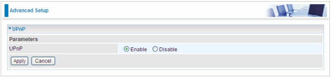
UPnP
UPnP offers peer-to-peer network connectivity for PCs and other network devices, along with control
and data transfer between devices. UPnP offers many advantages for users running NAT routers
through UPnP NAT Traversal, and on supported systems makes tasks such as port forwarding
much easier by letting the application control the required settings, removing the need for the user to
control advanced configuration of their device.
Both the user’s Operating System and the relevant application must support UPnP in addition to the
router. Windows XP and Windows Me natively support UPnP (when the component is installed), and
Windows 98 users may install the Internet Connection Sharing client from Windows XP in order to
support UPnP. Windows 2000 does not support UPnP.
UPnP:
L Enable: Check to enable the router’s UPnP functionality.
L Disable: Check to disable the router’s UPnP functionality.
233
Installing UPnP in Windows Example
Follow the steps below to install the UPnP in Windows Me.
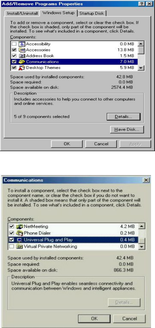
Step 1: Click Start and Control Panel. Double-click Add/Remove Programs.
Step 2: Click on the Windows Setup tab and select Communication in the Components selection
box. Click Details.
Step 3: In the Communications window, select the Universal Plug and Play check box in the
Components selection box.
Step 4: Click OK to go back to the Add/Remove Programs Properties window. Click Next.
234
Step 5: Restart the computer when prompted.
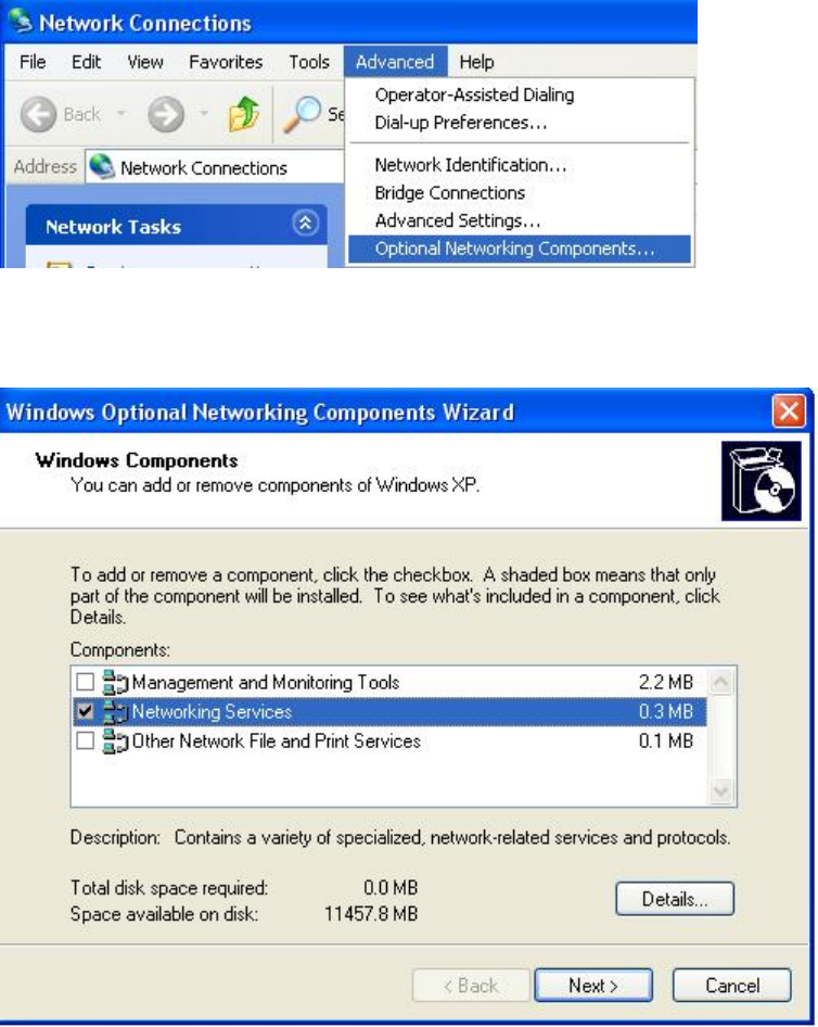
Follow the steps below to install the UPnP in Windows XP.
Step 1: Click Start and Control Panel.
Step 2: Double-click Network Connections.
Step 3: In the Network Connections window, click Advanced in the main menu and select Optional
Networking Components ….
The Windows Optional Networking Components Wizard window displays.
Step 4: Select Networking Service in the Components selection box and click Details.
235
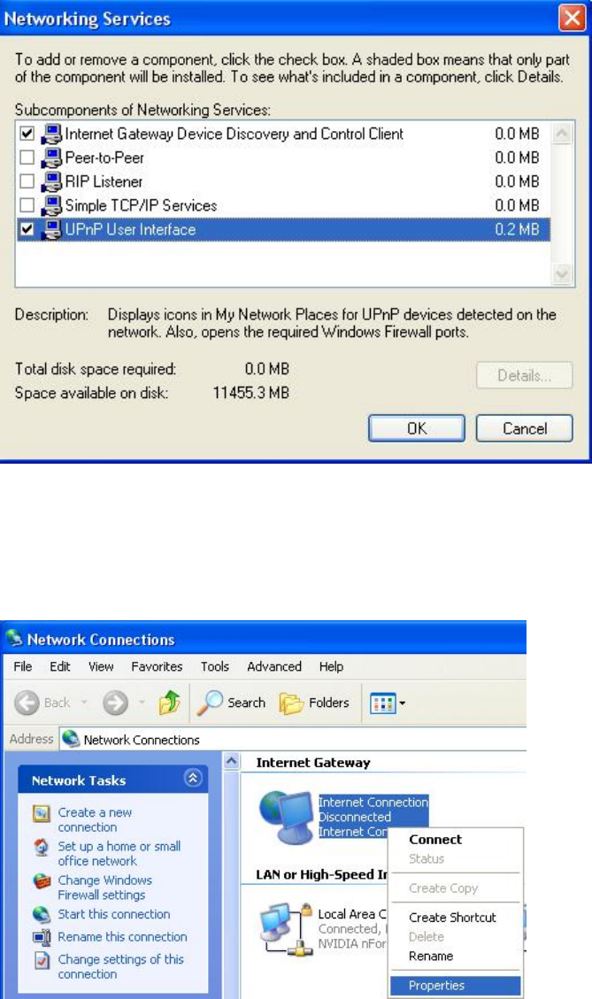
Step 5: In the Networking Services window, select the Universal Plug and Play check box.
Step 6: Click OK to go back to the Windows Optional Networking Component Wizard window and
click Next.
Auto-discover Your UPnP-enabled Network Device
Step 1: Click start and Control Panel. Double-click Network Connections. An icon displays under
Internet Gateway.
Step 2: Right-click the icon and select Properties.
236
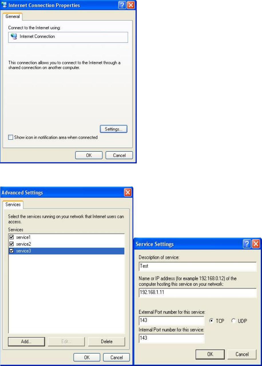
Step 3: In the Internet Connection Properties window, click Settings to see the port mappings that
were automatically created.
Step 4: You may edit or delete the port mappings or click Add to manually add port mappings.
Step 5: Select Show icon in notification area when connected option and click OK. An icon displays
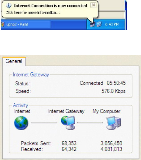
237
in the system tray
Step 6: Double-click on the icon to display your current Internet connection status.
238
Certificate
This feature is used for TR069 ACS Server authentication of the device using certificate, if
necessary. If the imported certificate does not match the authorized certificate of the ACS Server,
the device will have no access to the server.
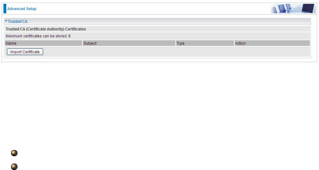
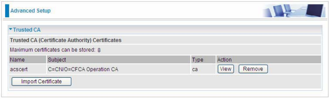
Trusted CA
Name: The certificate identification name.
Subject: The certificate subject.
Type: The certificate type information. "ca", indicates that the certificate is a CA-signed certificate.
"self", indicates that the certificate is a certificate owner signed one.
"x.509", indicates the certificate is the one created and signed according to the definition of Public-
Key System suggested by x.509.
Action:
View: view the certificate.
Remove: remove the certificate.
239
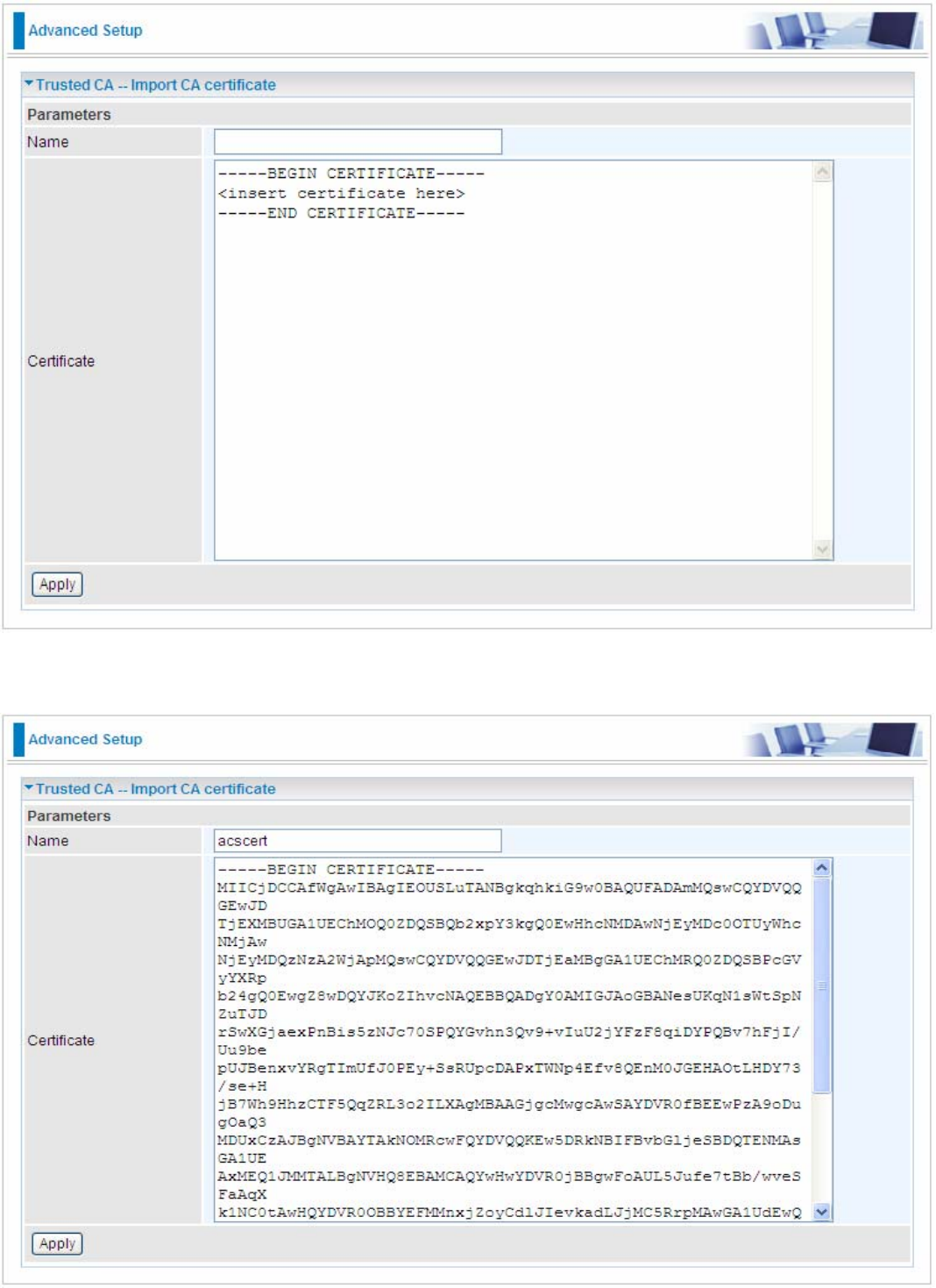
Click Import Certificate button to import your certificate.
Enter the certificate name and insert the certificate.
240
Click Apply to confirm your settings.
241
Multicast
Multicast is one of the three network transmission modes, Unicast, Multicast, Broadcast. It is a
transmission mode that supports point-to-multipoint connections between the sender and the
recipient. IGMP protocol is used to establish and maintain the relationship between IP host and the
host directly connected multicast router.
IGMP stands for Internet Group Management Protocol, it is a communications protocols used to
manage the membership of Internet Protocol multicast groups. IGMP is used by IP hosts and the
adjacent multicast routers to establish multicast group members. There are three versions for IGMP,
that is IGMPv1, IGMPv2 and IGMPv3.
MLD, short for Multicast Listener Discovery protocol, is a component if the Internet Protocol
version 6(IPv6) suite. MLD is used by IPv6 to discover multicast listeners on a directly attached link,
much as IGMP used in IPv4. The protocol is embedded in ICMPv6 instead of using a separate
protocol. MLDv1 is similar to IGMPv2 and MLDv2 is similar to IGMPv3.
IGMP
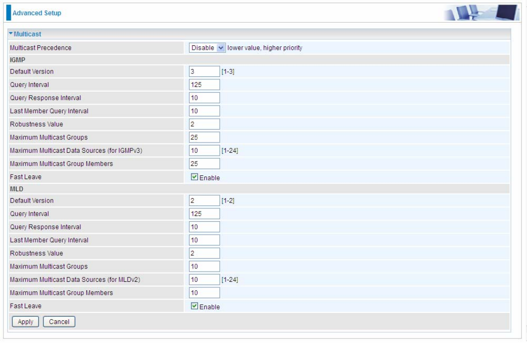
Multicast Precedence: It is for multicast QoS. With lower multicast precedence, IGMP packets will
be put into higher-priority queue. Default is set to disable.
Default Version: Enter the supported IGMP version, 1-3, default is IGMP v3.
Query Interval: Enter the periodic query interval time (sec) the multicast router sending the query
message to hosts to understand the group membership information.
Query Response Interval: Enter the response interval time (sec).
Last Member Query Interval: Enter the interval time (sec) the multicast router query the specified
group after it has received leave message.
242
Robustness Value: Enter the router robustness parameter, 2-7, the greater the robustness value,
the more robust the Querier is.
Maximum Multicast Groups: Enter the Maximum Multicast Groups.
Maximum Multicast Data Sources( for IGMP v3): Enter the Maximum Multicast Data Sources,1-
24.
Maximum Multicast Group Members: Enter the Maximum Multicast Group Members.
Fast leave: Check to determine whether to support fast leave. If this value is enabled, IGMP proxy
removes the membership of a group member immediately without sending an IGMP membership
query on downstream. This is very helpful if user wants fast channel (group change) changing in
cases like IPTV environment.
MLD
Default Version: Enter the supported MLD version, 1-2, default is MLDv2.
Query Interval: Enter the periodic query interval time (sec) the multicast router sending the query
message to hosts to understand the group membership information.
Query Response Interval: Enter the response interval time (sec).
Last Member Query Interval: Enter the interval time (sec) the multicast router query the specified
group after it has received leave message.
Robustness Value: Enter the router robustness parameter, default is 2, the greater the robustness
value, the more robust the Querier is.
Maximum Multicast Groups: Enter the Maximum Multicast Groups.
Maximum Multicast Data Sources( for MLDv2): Enter the Maximum Multicast Data Sources,1-24.
Maximum Multicast Group Members: Enter the Maximum Multicast Group Members.
Fast leave: Check to determine whether to support fast leave. If this value is enabled, MLD proxy
removes the membership of a group member immediately without sending an MLD membership
query on downstream. This is very helpful if user wants fast channel (group change) changing in
cases like IPTV environment.
.
243
Management
SNMP Agent
SNMP, Simple Network Management Protocol, is the most popular one in network. It consists of
SNMP Manager,SNMP Agent and MIB. Every network device supporting SNMP will have a SNMP
Agent which is a management software running in the device.
SNMP Manager, the management software running on the server, it uses SNMP protocol to send
GetRequest、GetNextRequest, SetRequest message to Agent to view and change the information
of the device.
SNMP Agents, the management software running in the device, accepts the message from the
manager, Reads or Writes the management variable in MIB accordingly and then generates
Response message to send it to the manager. Also, agent will send Trap message to the manager
when agent finds some exceptions.
Trap message, is the message automatically sent by the managed device without request to the
manager about the emergency events.
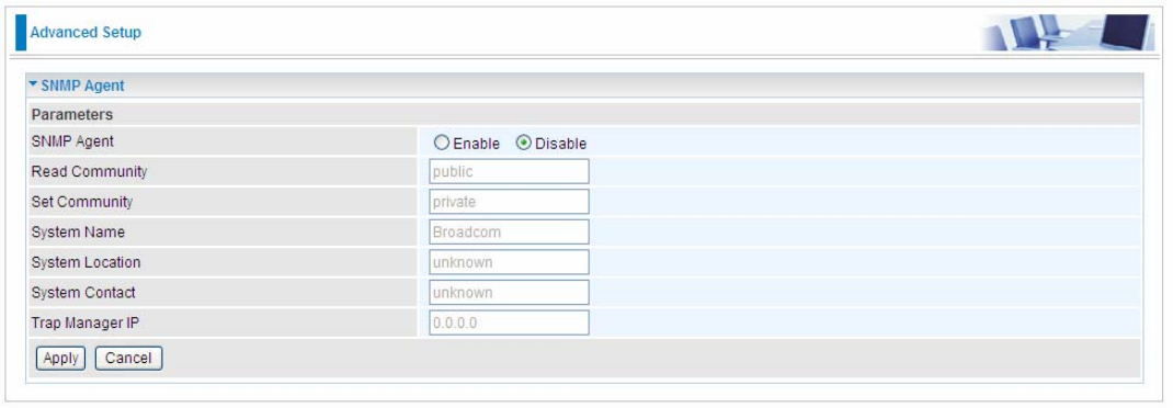
SNMP Agent: enable or disable SNMP Agent.
Read Community: Type the Get Community, which is the authentication for the incoming Get-and
GetNext requests from the management station.
Set Community: Type the Set Community, which is the authentication for incoming Set requests
from the management station.
System Name: here it refers to your router.
System Location: user-defined location.
System Contact: user-defined contact message.
Trap manager IP: enter the IP address of the server receiving the trap sent by SNMP agent.
244
TR-069 Client
TR-069 (short for Technical Report 069) is a DSL Forum (which was later renamed as Broadband
Forum) technical specification entitled CPE WAN Management Protocol (CWMP). It defines an
application layer protocol for remote management of end-user devices.
As a bidirectional SOAP/HTTP based protocol it can provides the communication between customer
premises equipment (CPE) and Auto Configuration Server (ACS). It includes both a safe
configuration and the control of other CPE management functions within an integrated framework. In
the course of the booming broadband market, the number of different internet access possibilities
grew as well (e.g. modems, routers, gateways, set-top box, VoIP-phones).At the same time the
configuration of this equipment became more complicated –too complicated for end-users. For this
reason, TR-069 was developed. It provides the possibility of auto configuration of the access types.
Using TR-069 the terminals can get in contact with the Auto Configuration Servers (ACS) and
establish the configuration automatically and let ACS configure CPE automatically.
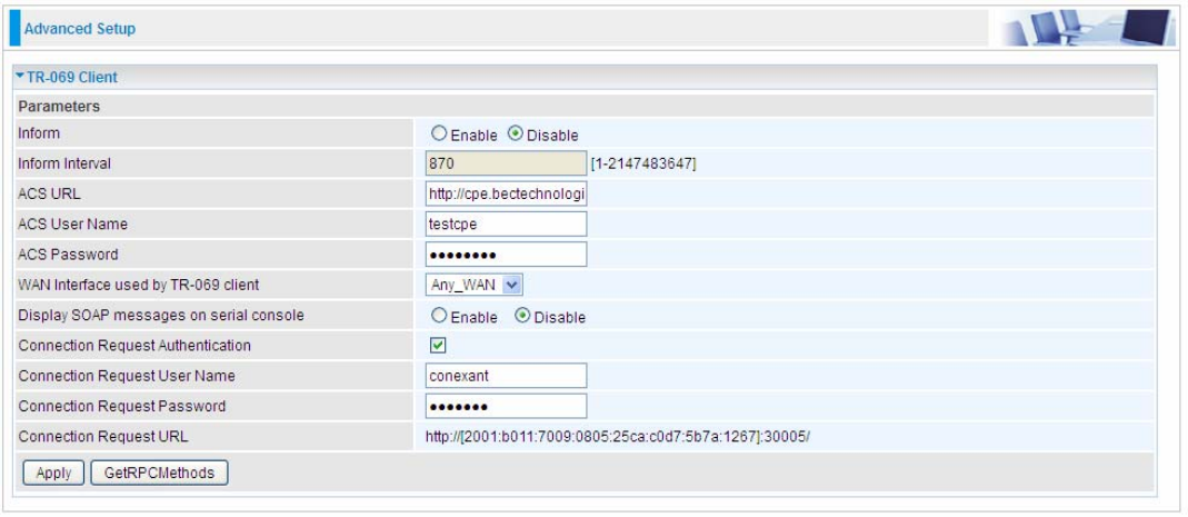
Inform: select enable to let CPE be authorized to send Inform message to automatically connect to
ACS.
Inform Interval: Specify the inform interval time (sec) which CPE used to periodically send inform
message to automatically connect to ACS. When the inform interval time arrives, the CPE will send
inform message to automatically connect to ACS.
ACS URL: Enter the ACS server login name.
ACS User Name: Specify the ACS User Name for ACS authentication to the connection from CPE.
ACS password: Enter the ACS server login password.
WAN interface used by TR-069: select the interface used by TR-069.
Display SOAP message on serial console: select whether to display SOAP message on serial
console.
Connection Request Authentication: Check to enable connection request authentication feature.
Connection Request User Name: Enter the username for ACS server to make connection request.
Connection Request User Password: Enter the password for ACS server to make connection
request.
Connection Request URL: Automatically match the URL for ACS server to make connection
request.
245
GetRPCMethods:Supported by both CPE and ACS, display the supported RFC listing methods.
Click Apply to apply your settings.
246
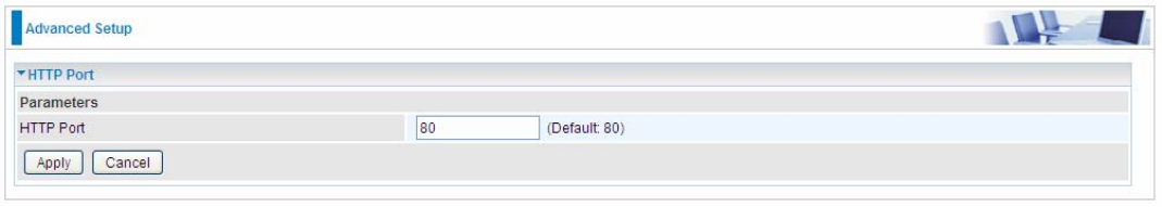
HTTP Port
The device equips user to change the embedded web server accessing port. Default is 80.
247
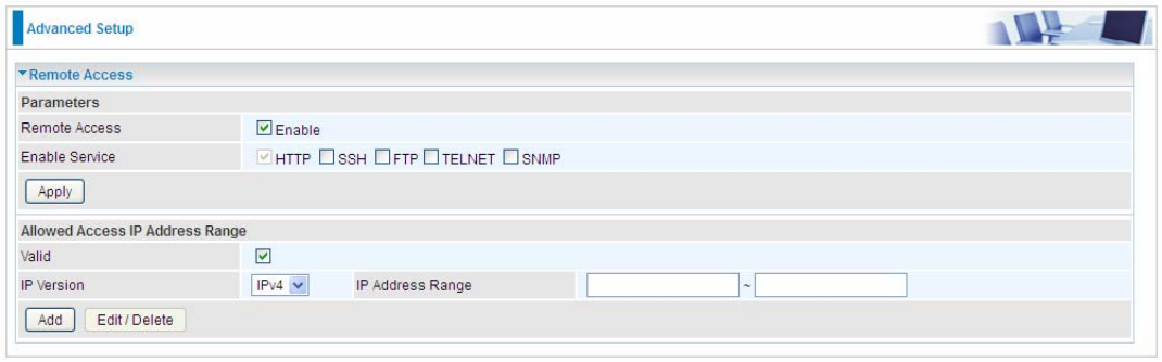
Remote Access
It is to allow remote access to the router to view or configure.
Remote Access: Select “Enable” to allow management access from remote side (mostly from
internet). If disabled, no remote access is allowed for any IPs even if you set allowed access IP
address. So, please note that enabling remote access is an essential step before granting remote
access to IPs.
Enable Service: Select to determine which service(s) is (are) allowed for remote access when
remote access is enabled. By default (on condition that remote access is enabled), the web service
(HTTP) is allowed for remote access.
Click Apply button to submit your settings.
"Allowed Access IP Address Range" was used to restrict which IP address could login to access
system web GUI.
Valid: Enable/Disable Allowed Access IP Address Range
IP Address Range: Specify the IP address Range, IPv4 and IPv6 address range can be supported,
users can set IPv4 and IPv6 address range individually.
Click Add to add an IP Range to allow remote access.
Note: 1. If user wants to grant remote access to IPs, first enable Remote Access.
2. Remote Access enabled:
1) Enable Valid for the specific IP(s) in the IP range to allow the specific IP(s) to remote access the
router.
2) Disable Valid for all specific IP(s) in the IP range to allow any IP(s) to remote access the router.
3) No listing of IP range is to allow any IP(s) to remote access the router.
248
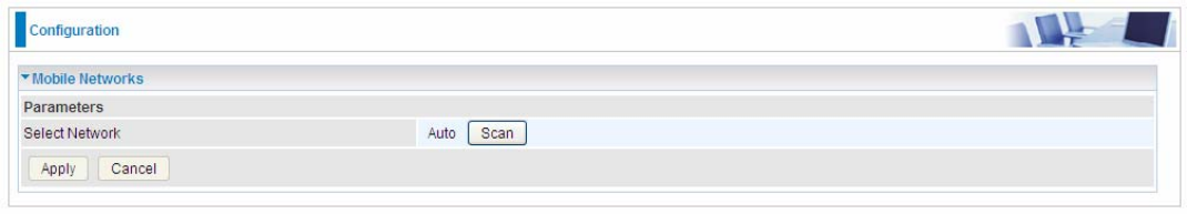
Mobile Networks
User can press Scan to discover available 3G/4G LTE mobile network.
249
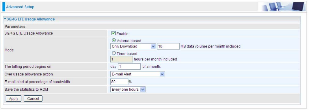
3G/4G LTE Usage Allowance
3G/4G LTE usage allowance is designated for users to monitor and control the 3G flow usage.
8920NXL-600’s 3G/4G LTE usage allowance offers exact control settings for each SIM card.
3G/LTE Usage Allowance: Enable to monitor 3G/4G LTE usage.
Mode: include Volume-based and Time-based control.
L Volume-based include “only Download”, ”only Upload” and “Download and Upload” to limit
the flow.
L Time-based control the flow by providing specific hours per month.
The billing period begins on: The beginning day of billing each month.
Over usage allowance action: What to do when the flow is over usage allowance, the available
methods are “E-mail Alert”, ”Email Alert and Disconnect” and “Disconnect”.
E-mail alert at percentage of bandwidth: When the used bandwidth exceeds the set proportion,
the system will send email to alert.
Save the statistics to ROM: To save the statistics to ROM system.
250
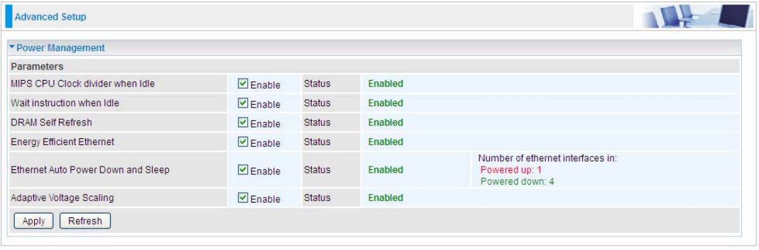
Power Management
Power management is a feature of some electrical appliances, especially computers that turn off the
power or switch to a low-power state when inactive.
Five main parameters are listed for users to check to manage the performance of the router.
251
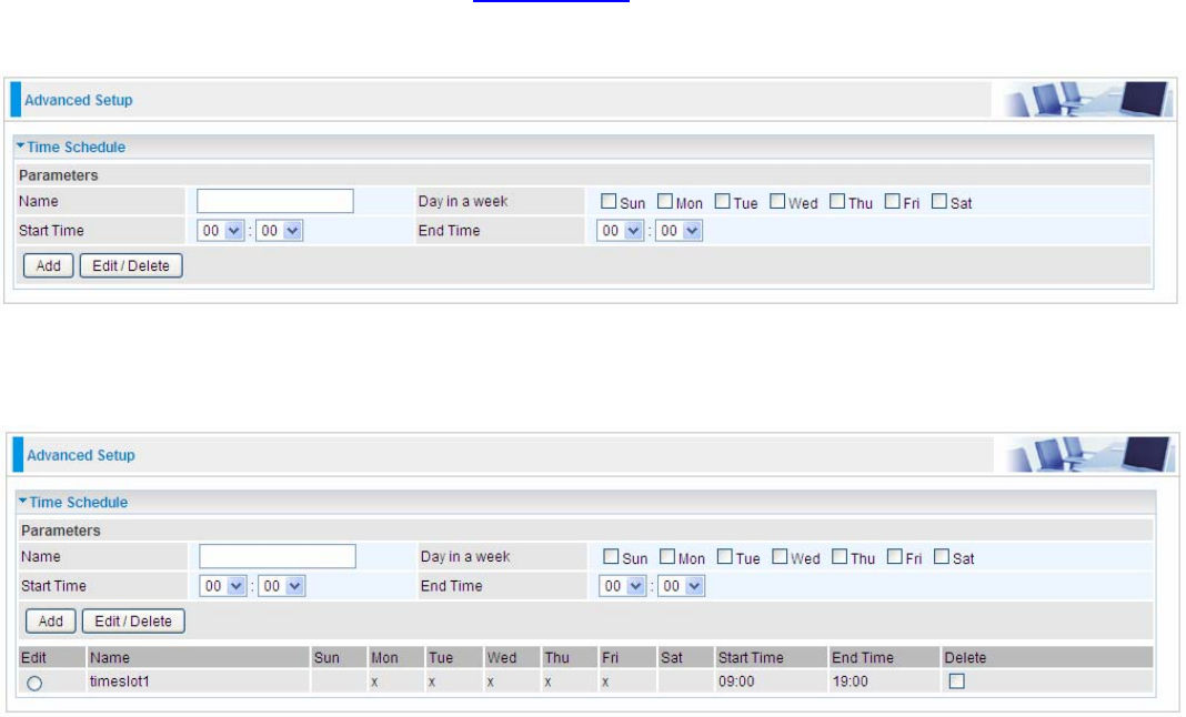
Time Schedule
The Time Schedule supports up to 32 timeslots which helps you to manage your Internet connection.
In each time profile, you may schedule specific day(s) i.e. Monday through Sunday to restrict or
allowing the usage of the Internet by users or applications.
This Time Schedule correlates closely with router’s time, since router does not have a real time
clock on board; it uses the Simple Network Time Protocol (SNTP) to get the current time from an
SNTP server from the Internet. Refer to Internet Time for details. You router time should synchronize
with NTP server.
For example, user can add a timeslot named “timeslot1” features a period of 9:00-19:00 on every
weekday.
252
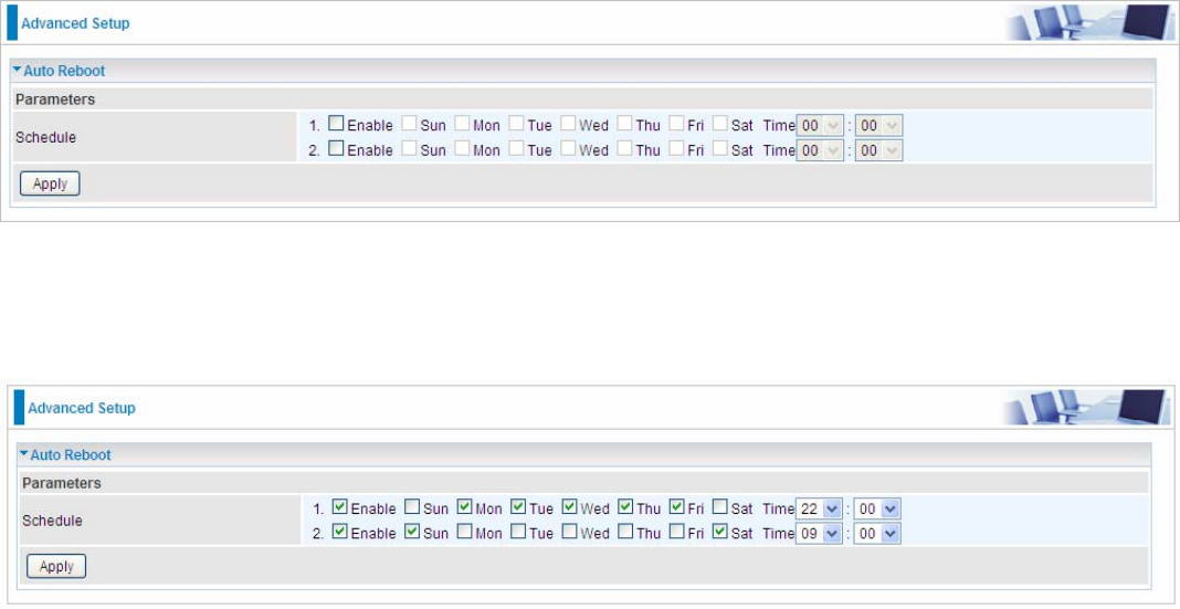
Auto Reboot
Auto reboot offers flexible rebooting service (reboot with the current configuration) of router for users
in line with scheduled timetable settings.
Enable to set the time schedule for rebooting.
For example, the router is scheduled to reboot at 22:00 every single weekday, and to reboot at 9:00
on Saturday and Sunday. You can set as follows:
253
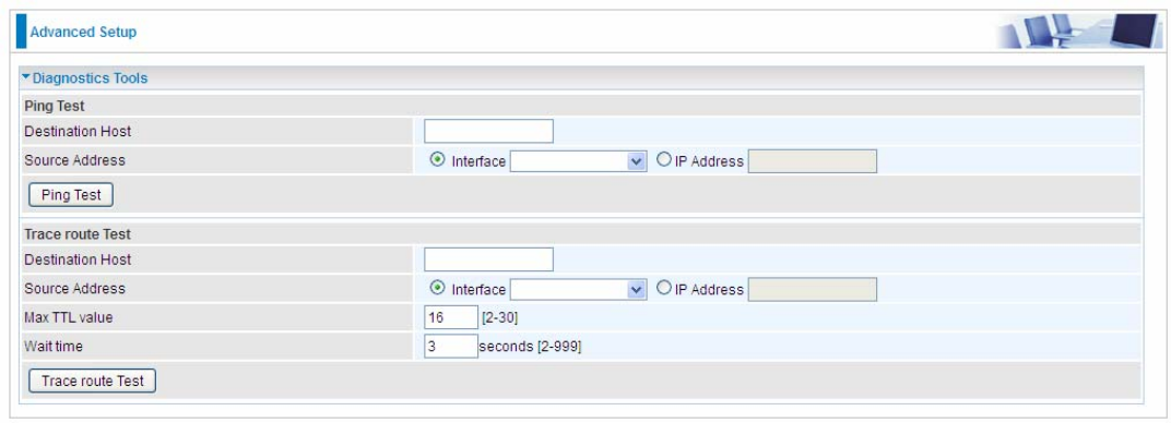
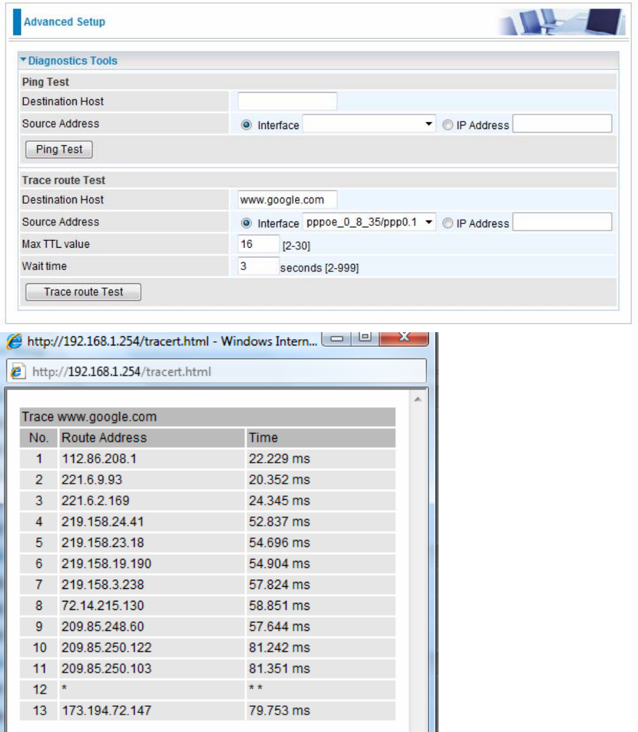
Diagnostics
Diagnostics Tools
BiPAC 8920NXL-600 offers diagnostics tools including “Ping” and “Trace route test” tools to check
for problems associated with network connections.
Ping Test: to verify the connectivity between source and destination.
Destination Host: Enter the destination host (IP, domain name) to be checked for connectivity.
Source Address: Select or set the source address to test the connectivity from the source to the
destination.
Ping Test: Press this button to proceed ping test.
Trace route Test: to trace the route to see how many hops (also see the exact hops) the packet of
data has to take to get to the destination.
Destination Host: Set the destination host (IP, domain name) to be traced.
Source Address: Select or set the source address to trace the route from the source to the
destination.
Max TTL value: Set the max Time to live (TTL) value.
Wait time: Set waiting time for each response in seconds.
254
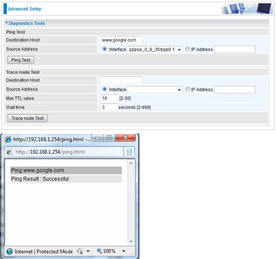
Example: Ping www.google.com
255
Example: “trace” www.google.com
256
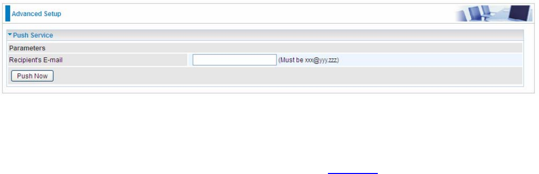
Push Service
With push service, the system can send email messages with consumption data and system
information.
Recipient’s E-mail: Enter the destination mail address. The email is used to receive system log ,
system configuration,security log sent by the device when the Push Now button is pressed
(information sent only when pressing the button ), but the mail address is not remembered.
Note: Please first set correct the SMTP server parameters in Mail Alert.
257
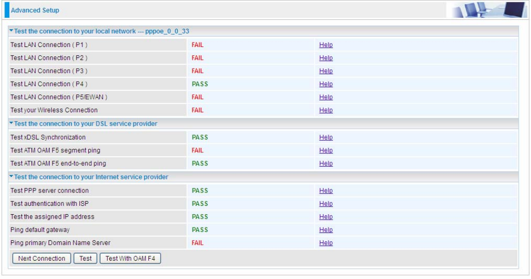
Diagnostics
Check the connections, including Ethernet connection, Internet Connection and wireless connection.
Click Help link that can lead you to the interpretation of the results and the possible, simply
troubleshooting.
258
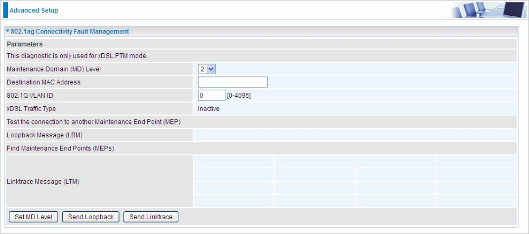
Fault Management
IEEE 802.1ag Connectivity Fault Management (CFM) is a standard defined by IEEE. It defines
protocols and practices for OAM (Operations, Administration, and Maintenance) for paths through
802.1 bridges and local area networks (LANs). Fault Management is to uniquely test the PTM
connection; Push service
Maintenance Domain (MD) Level: Maintenance Domains (MDs) are management spaces on a
network, typically owned and operated by a single entity. MDs are configured with Names and
Levels, where the eight levels range from 0 to 7. A hierarchal relationship exists between domains
based on levels. The larger the domain, the higher the level value.
Maintenance End Point: Points at the edge of the domain, define the boundary for the domain. A
MEP sends and receives CFM frames through the relay function, drops all CFM frames of its level or
lower that come from the wire side.
Link Trace: Link Trace messages otherwise known as Mac Trace Route are Multicast frames that a
MEP transmits to track the path (hop-by-hop) to a destination MEP which is similar in concept to
User Datagram Protocol (UDP) Trace Route. Each receiving MEP sends a Trace route Reply directly
to the Originating MEP, and regenerates the Trace Route Message.
Loop-back: Loop-back messages otherwise known as Mac ping are Unicast frames that a MEP
transmits, they are similar in concept to an Internet Control Message Protocol (ICMP) Echo (Ping)
messages, sending Loop-back to successive MIPs can determine the location of a fault. Sending a
high volume of Loop-back Messages can test bandwidth, reliability, or jitter of a service, which is
similar to flood ping. A MEP can send a Loop-back to any MEP or MIP in the service. Unlike CCMs,
Loop back messages are administratively initiated and stopped.
259
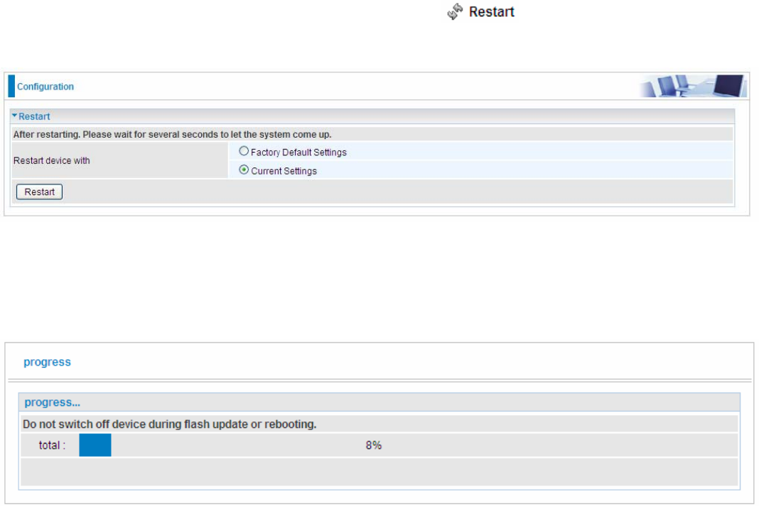
Restart
This section lets you restart your router if necessary. Click in the low right corner of each
configuration page.
If you wish to restart the router using the factory default settings (for example, after a firmware
upgrade or if you have saved an incorrect configuration), select Factory Default Settings to reset to
factory default settings. Or you just want to restart after the current setting, the select the Current
Settings, and Click Restart.

260
Chapter 5: Troubleshooting
If your router is not functioning properly, please refer to the suggested solutions provided in this
chapter. If your problems persist or the suggested solutions do not meet your needs, please kindly
contact your service provider or Billion for support.
Problems with the router
Problem
Suggested Action
None of the LEDs is on when you turn
on the router Check the connection between the router and the
adapter. If the problem persists, most likely it is due
to the malfunction of your hardware. Please contact
your service provider or Billion for technical support.
Y
ou have forgotten your login username
or password Try the default username "admin" and password
"admin". If this fails, you can restore your router to
its factory settings by pressing the reset button on
the device rear side.
Problems with WAN interface
Problem
Suggested Action
Frequent loss of ADSL line sync
(disconnections) Ensure that all other devices connected to the same
telephone line as your router (e.g. telephones, fax
machines, analogue modems) have a line filter
connected between them and the wall socket (unless
you are using a Central Splitter or Central Filter
installed by a qualified and licensed electrician), and
ensure that all line filters are correctly installed and the
right way around. Missing line filters or line filters
installed the wrong way around can cause problems
with your ADSL connection, including causing frequent
disconnections. If you have a back-to-base alarm
system you should contact your security provider for a
technician to make any necessary changes.

261
Problem with LAN interface
Problem
Suggested Action
Cannot PING any PC on LAN Check the Ethernet LEDs on the front panel.
The LED should be on for the port that has a PC
connected. If it does not lit, check to see if the cable
between your router and the PC is properly
connected. Make sure you have first uninstalled your
firewall program before troubleshooting.
Verify that the IP address and the subnet mask are
consistent for both the router and the workstations.

262
Appendix: Product Support & Contact
If you come across any problems please contact the dealer from where you purchased your
product.
Contact Billion
Worldwide:
http://www.billion.com
MAC OS is a registered Trademark of Apple Computer, Inc.
Windows XP, Windows Vista, Windows 7 and Windows 8 are registered Trademarks of Microsoft
Corporation.
263
Federal Communication Commission Interference Statement
This equipment has been tested and found to comply with the limits for a Class B digital device,
pursuant to Part 15 of the FCC Rules. These limits are designed to provide reasonable protection
against harmful interference in a residential installation. This equipment generates, uses, and can
radiate radio frequency energy and, if not installed and used in accordance with the instructions,
may cause harmful interference to radio communications. However, there is no guarantee that
interference will not occur in a particular installation. If this equipment does cause harmful
interference to radio or television reception, which can be determined by turning the equipment off
and on, the user is encouraged to try to correct the interference by one or more of the following
measures:
Reorient or relocate the receiving antenna.
Increase the separation between the equipment and receiver.
Connect the equipment into an outlet on a circuit different from that to which the receiver is
connected.
Consult the dealer or an experienced radio/TV technician for help.
FCC Caution:
This device complies with Part 15 of the FCC Rules. Operation is subject to the following two
conditions:
(1) This device may not cause harmful interference
(2) This device must accept any interference received, including interference that may cause
undesired operation.
Any changes or modifications not expressly approved by the party responsible for compliance
could void the user's authority to operate this equipment. . This device and its antenna(s) must not
be co-located or operating in conjunction with any other antenna or transmitter.
Co-location statement
This device and its antenna(s) must not be co-located or operating in conjunction with any other
antenna or transmitter.
FCC Radiation Exposure Statement
This equipment complies with FCC radiation exposure limits set forth for an uncontrolled
environment. This equipment should be installed and operated with minimum distance 20cm
between the radiator & your body.