Billion Electric BIL-8920NX600 Dual-lines VDSL2/ADSL2+ Wireless-N 600Mbps 3G/4G LTE VPN Firewall Router User Manual 2
Billion Electric Co., Ltd. Dual-lines VDSL2/ADSL2+ Wireless-N 600Mbps 3G/4G LTE VPN Firewall Router Users Manual 2
Contents
- 1. Users Manual-1
- 2. Users Manual-2
- 3. Users Manual-3
Users Manual-2
122
System
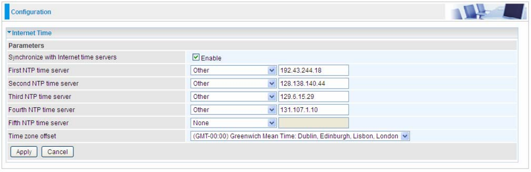
Internet Time
The router does not have a real time clock on board; instead, it uses the Network Time Protocol
(NTP) to get the most current time from an NTP server.
NTP is a protocol for synchronization of computers. It can enable computers synchronize to the NTP
server or clock source with a high accuracy.
Choose the NTP time server from the drop-down menu, if you prefer to specify an NTP server other
than those in the drop-down list, simply enter its IP address in their appropriate blanks provided as
shown above. Your ISP may also provide an SNTP server for you to use.
Choose your local time zone from the drop-down menu. After a successful connection to the Internet,
the router will retrieve the correct local time from the NTP server you have specified. If you prefer to
specify an NTP server other than those in the drop-down list, simply enter its IP address in their
appropriate blanks provided as shown above. Your ISP may also provide an NTP server for you to
use.
Click Apply to apply your settings.
123
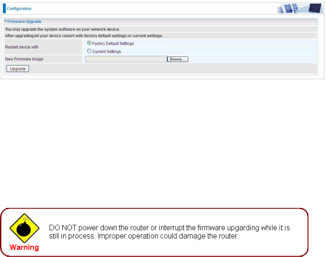
Firmware Upgrade
Software upgrading lets you experience new and integral functions of your router.
Restart device with:
L Factory Default Settings: Restart the device with factory default settings automatically when
finishing upgrading.
L Current Settings: Restart the device with the current settings automatically when finishing
upgrading.
Your router’s “firmware” is the software that allows it to operate and provides all its functionality.
Think of your router as a dedicated computer, and the firmware as the software it runs. Over time
this software may be improved and revised, and your router allows you to upgrade the software it
runs to take advantage of these changes.
Clicking on Browse will allow you to select the new firmware image file you have downloaded to
your PC. Once the correct file is selected, click Upgrade to update the firmware in your router.
124
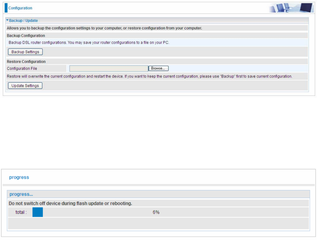
Backup / Update
These functions allow you to save and backup your router’s current settings to a file on your PC, or
to restore from a previously saved backup. This is useful if you wish to experiment with different
settings, knowing that you have a backup handy in the case of any mistakes. It is advisable to
backup your router’s settings before making any significant changes to your router’s configuration.
Click Backup Settings, a window appears, click save , then browse the location where you want to
save the backup file.
Click Browse and browse to the location where your backup file is saved, the click Open. Then in
the above page, click Update Settings, the following process indicating screen will appear. Let it
update to 100%, it will automatically turn to the Device Info page.
125
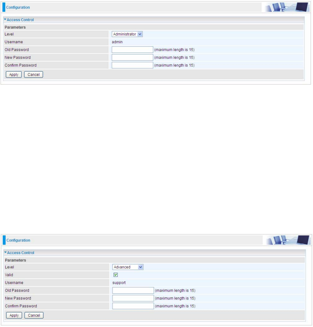
Access Control
Access Control is used to prevent unauthorized access to the router configuration page. Here you
can change the login user password. Three user levels are provided here. Each user level there’s a
default provided user. You must access the router with the appropriate username and password.
Here the corresponding passwords are allowed to change.
Level: select which level you want to change password to. There are three default levels.
L Administrator: the root user, corresponding default username and password are admin and
admin respectively.
L Advanced: username for the remote user to login, corresponding default username and
password are support and support respectively.
L User: username for the general user, when logon to the web page, only few items would be
listed for common user, corresponding default username password are user and user
respectively.
Username: The default username for each user level.
Old Password: Enter the old password.
New Password: Enter the new password.
Confirm Password: Enter again the new password to confirm.
Note: By default the accounts of Advanced and User are disabled, please click Valid check-box to
activate the accounts.
Click Apply to apply your new settings.
126
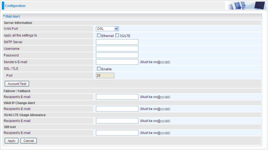
Mail Alert
Mail alert is designed to keep system administrator or other relevant personnel alerted of any
unexpected events that might have occurred to the network computers or server for monitoring
efficiency. With this alert system, appropriate solutions may be tackled to fix problems that may have
arisen so that the server can be properly maintained.
WAN Port: Mail Alert feature can be applicable to every WAN mode: Ethernet,DSL and 3G/4G
LTE. Select the port you want to use Mail Alert.
For example DSL, then when the WAN connection is in DSL mode and when there is any
unexpected event, the alert message will be sent to your specified E-mail.
Apply all settings to: check whether you want to have a copy of the settings to apply to other WAN
port, suppose the above Main port is DSL, then if you enable this function, then Ethernet port will
have the same configuration.
SMTP Server: Enter the SMTP server that you would like to use for sending emails.
Username: Enter the username of your email account to be used by the SMTP server.
Password: Enter the password of your email account.
Sender’s Email: Enter your email address.
SSL/TLS: Check to whether to enable SSL/TLS encryption feature.
Port: the port, default is 25.
Account Test: Press this button to test the connectivity and feasibility to your sender’s e-mail.
Recipient’s Email (Failover / Failback): Enter the email address that will receive the alert message
once the WAN-interface failover or failback occurs.
Recipient’s Email (WAN IP Change Alert): Enter the email address that will receive the alert
message once a WAN IP change has been detected.
Recipient’s Email (3G/4G LTE Usage Allowance ): Enter the email address that will receive the
alert message once the 3G over Usage Allowance occurs.
Recipient’s Email (SIM lost): Enter the email address that will receive the alert message once the
127
SIM card loss has been detected.
128
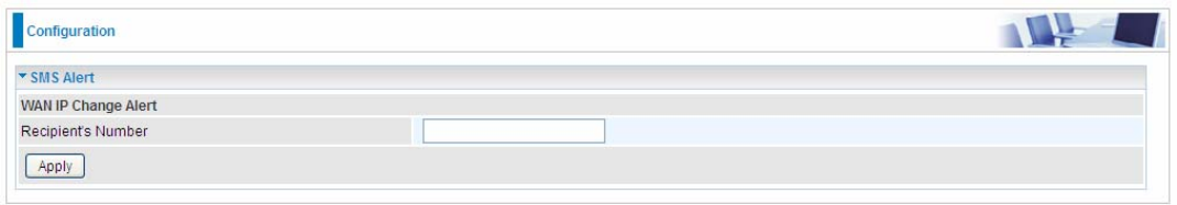
SMS Alert
SMS, Short Message Service, is to inform clients the information clients subscribe. The BiPAC
8920NXL-600 offers SMS alert sending clients alert messages when a WAN IP change is detected.
Recipient’s Number (WAN IP Change Alert): Enter the Recipient’s number that will receive the
alert message once a WAN IP change has been detected.
129
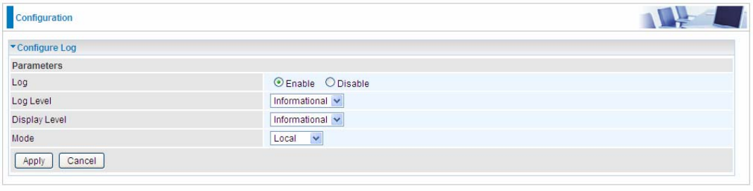
Configure Log
Log: Enable or disable this function.
Log level: Select your log level. The log level allows you to configure which types of events are
logged. There are eight log levels from high to low are displayed below:
L Emergency = system is unusable
L Alert = action must be taken immediately
L Critical = critical conditions
L Error = error conditions
L Warning = warning conditions
L Notice = normal but significant conditions
L Informational = information events
L Debugging = debug-level messages
The gateway records all log events at the chosen level and above. For instance, if you set the log
level to Critical, all critical, alert, and emergency events are logged, but none of the others are
recorded
Display Level: Display the log according to the level you set when you view system log. Once you
set the display level, the logs of the same or higher priority will be displayed.
Mode: Select the mode the system log adopted. Three modes: local, Remote and Both.
L Local: Select this mode to store the logs in the router’s local memory.
L Remote: Select this mode to send the log information to a remote log server. Then you must
assign the remote log server and port, 514 is often used.
L Both: Logs stored adopting above two ways.
Click Apply to save your settings.
130
USB
Storage here refers to network sharing in the network environment, USB devices act as the storage
carrier for DLNA, common file sharing.
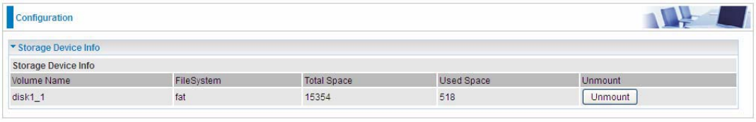
Storage Device Info
This part provides users direct access to the storage information like the total volume, the used and
the remaining capacity of the device.
Volume Name: Display the storage volume name
FileSystem: Display the storage device’s file system format, well-known is FAT.
Total Space: Display the total space of the storage, with unit MB.
Used Space: Display the remaining space of each partition, unit MB.
Unmount: Click Unmount button if you want to uninstall the USB device. Please Note that first click
Unmount before you uninstall your USB storage.
131
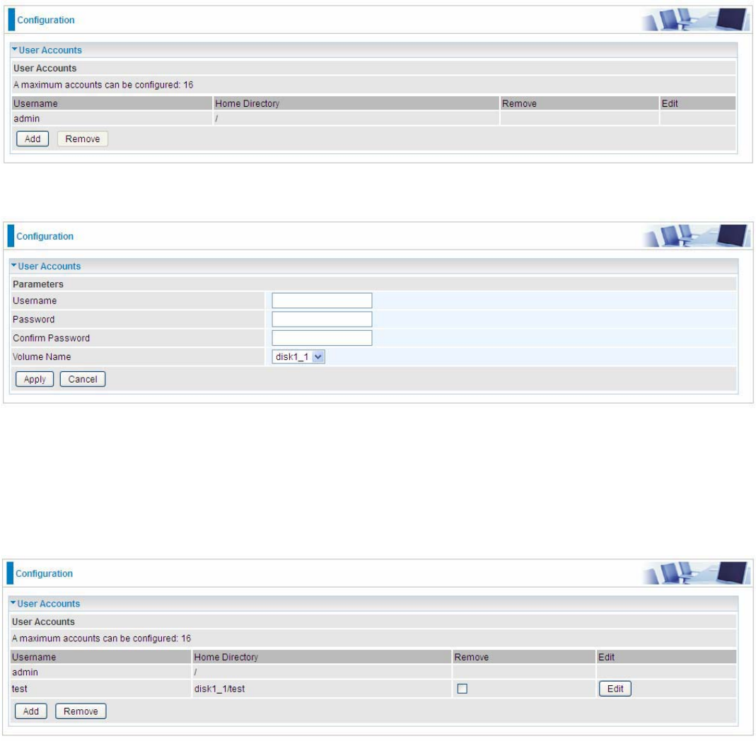
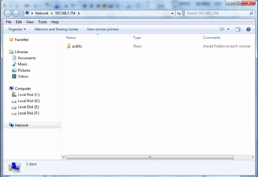
User Accounts
Users here can add user accounts for access to the storage, in this way users can access the
network sharing storage with the specified account, and again protect their own data.
Default user admin.
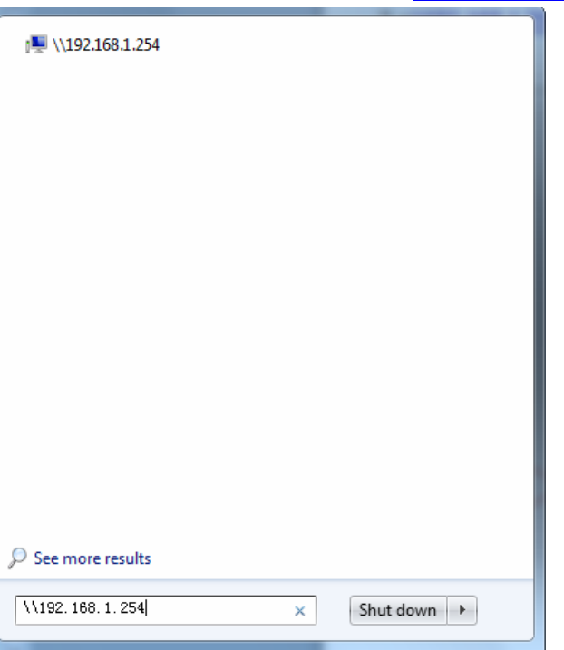
Click Add button, enter the user account-adding page:
Username: user-defined name, but simpler and more convenient to remember would be favorable.
Password: Set the password.
Confirm Password: Reset the password for confirmation.
Volume Name: Select Volume name, as to create access to the volume of the specified partition of
the storage.
For example, a user test is setup behind the disk1_1.
133
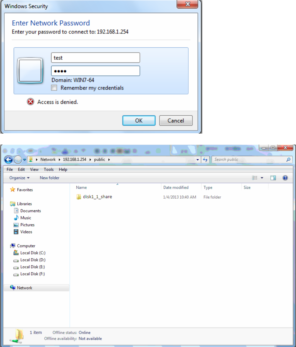
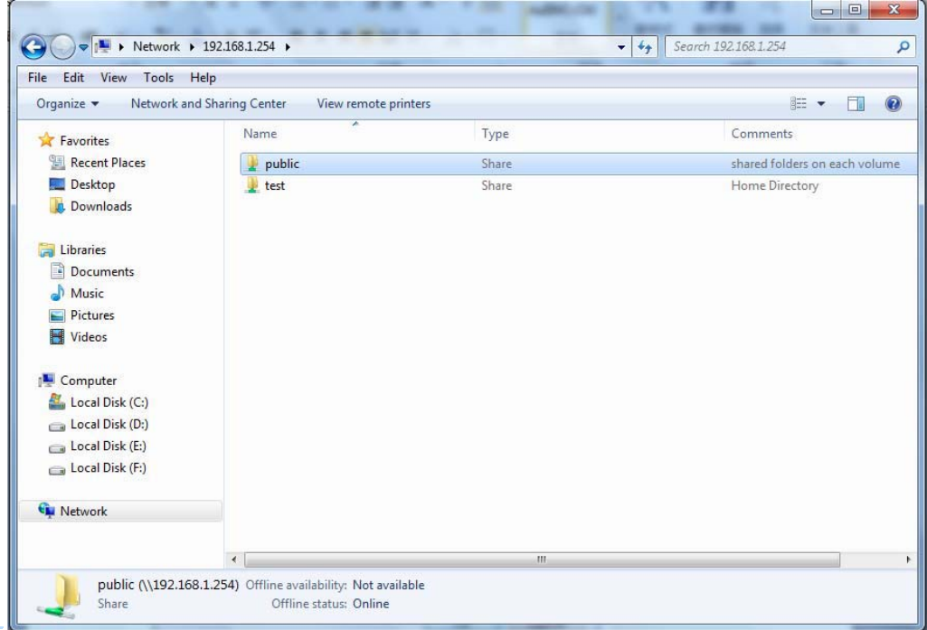
When accessing the network storage, you can see a folder named “public”, users should have the
account to enter, and the account can be set at the User Accounts section.
When first logged on to the network folder, you will see the “public” folder.
Public: The public sharing space for each user in the USB Storage.
When user register a USB account and log successfully, a private folder (the same name as the user
account registered) exclusive for each user is established. Go on to see the details.
134
Access the folder public.
135
When successfully accessed, the private folder of each user is established, and user can see from
the following picture. The test fold in the picture is the private space for each user.
136
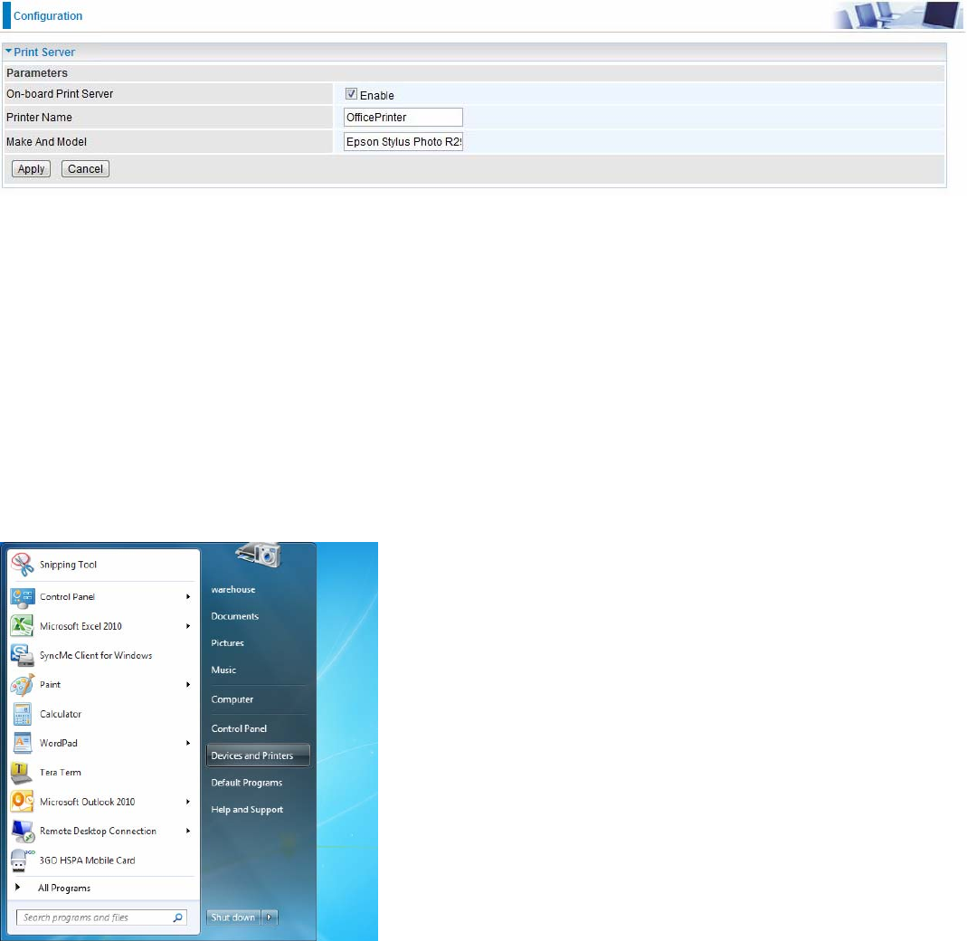
Print Server
The Print Server feature allows you to share a printer on your network by connecting a USB cable
from your printer to the USB port on the BiPAC 8920NX(L)-600. This allows you to print from any
location on your network.
Note: Only USB printers are supported.
Setup of the printer is a 3 -step process
1. Connect the printer to the router’s USB port
2. Enable the print server on the router
3. Install the printer drivers on the PC you want to print from
On-board Print Server: Check Enable to activate the print server
Printer Name: Enter the Printer name, for example, OfficePrinter
Make and Model: Enter in the Make and Model information for the printer, for example, Epson
Stylus Photo R290
Note:
The Printer name can be any text string up to 40 characters. It cannot contain spaces.
The Make and Model can be any text string up to 128 characters.
Set up of Printer client (Windows 7)
Step 1: Click Start and select “Devices and Printers”
137
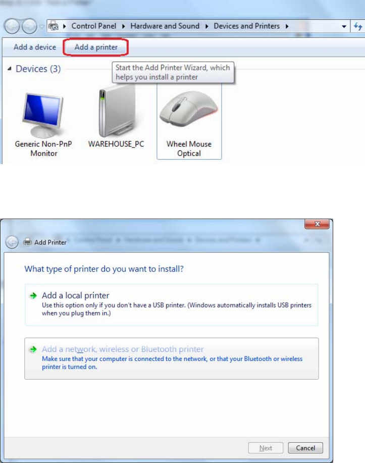
Step 2: Click ‘’Add a Printer’’.
Step 3: Click “Add a network, wireless or Bluetooth printer
138
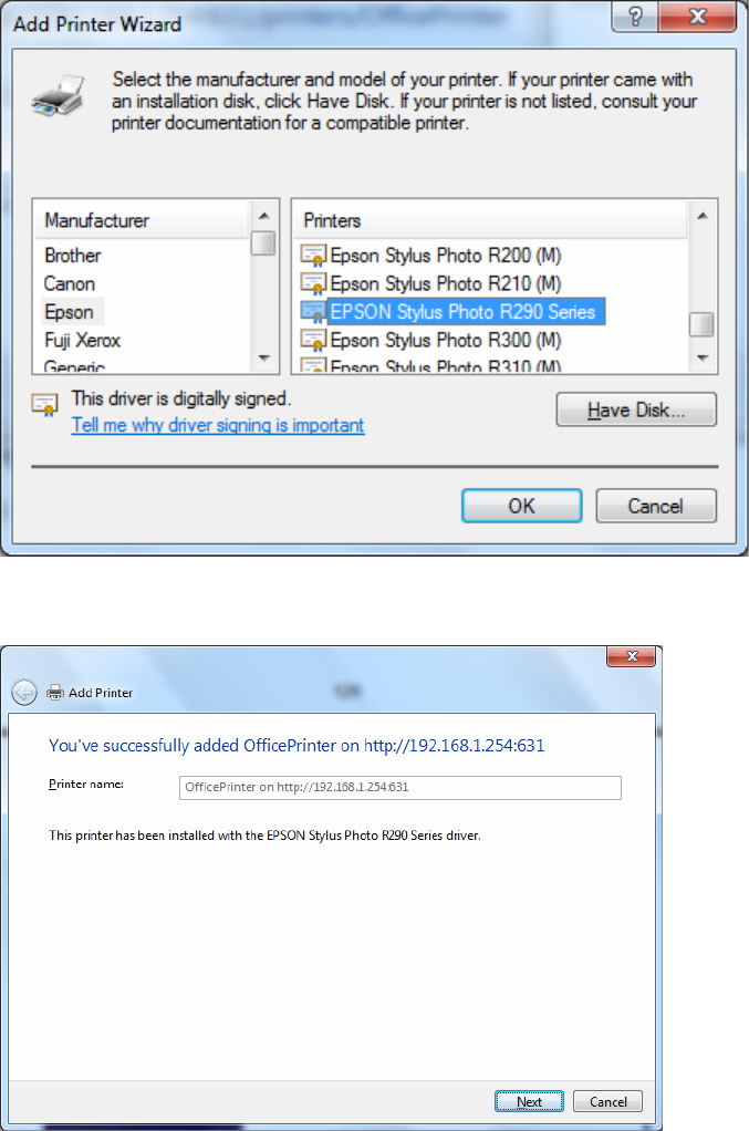
Step 4: Click “The printer that I want isn’t listed”
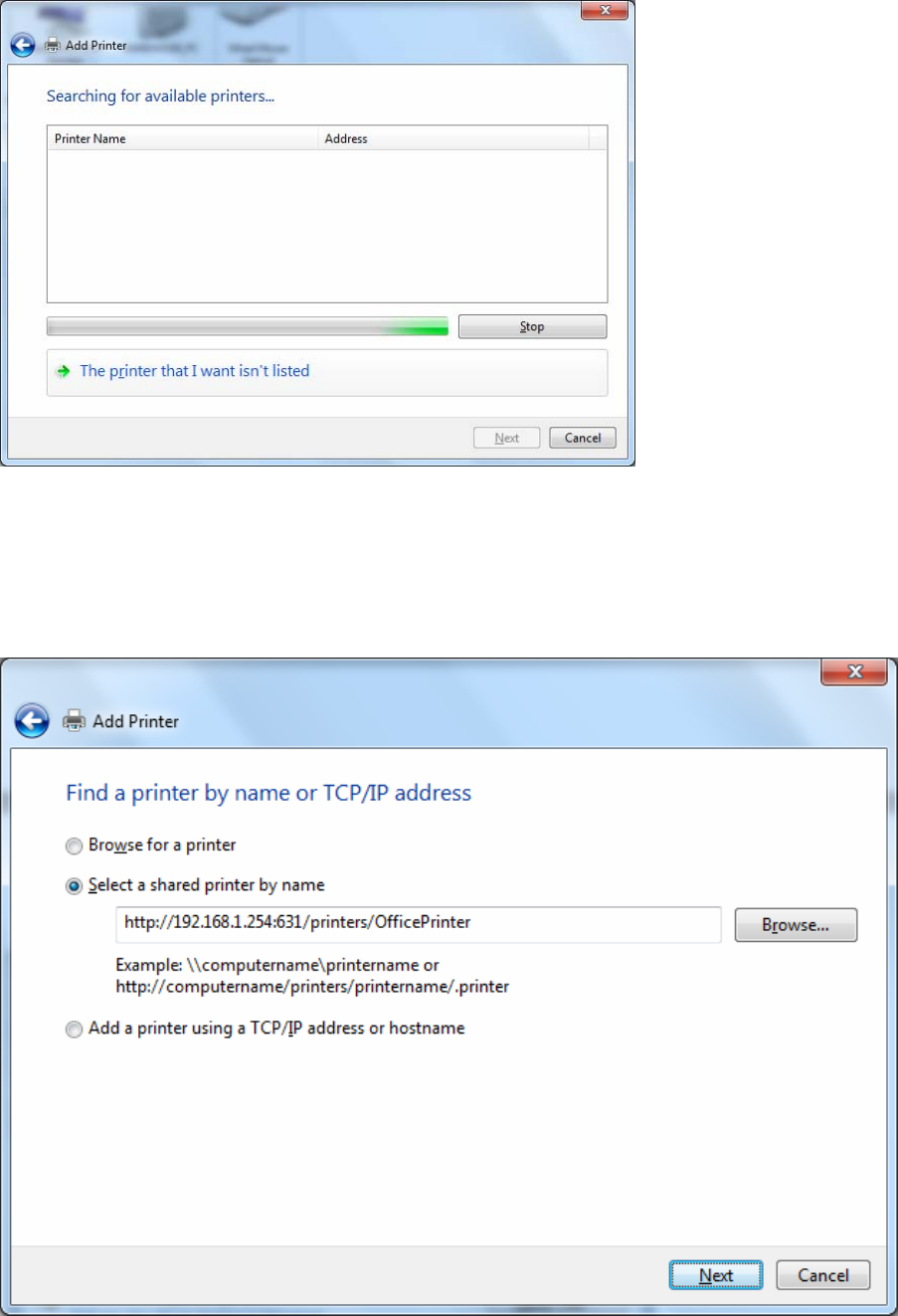
Step 5: Select “Select a shared printer by name”
Enter http://8920NXL600- LAN-IP:631/printers/printer-name or. Make sure printer’s name is the same as what you
set in the router earlier
For Example: http://192.168.1.254:631/printers/OfficePrinter
OfficePrinter is the Printer Name we setup earlier
139
Step 6: Click “Next” to add the printer driver. If your printer is not listed and your printer came with an installation
disk, click “Have Disk” find it and install the driver.
Step 7: Click “Next”
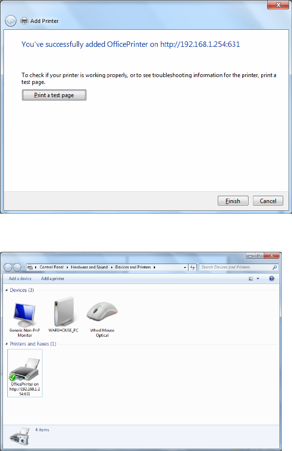
140
Step 8: Click “Next” and you are done
You will now be able to see your printer on the Devices and Printers Page
141
DLNA
The Digital Living Network Alliance (DLNA) is a non-profit collaborative trade organization
established by Sony in June 2003, which is responsible for defining interoperability guidelines to
enable sharing of digital media between consumer devices such as computers, printers, cameras,
cell phones and other multiple devices.
DLNA uses Universal Plug and Play (UPnP) for media management, discovery and control. UPnP
defines the types of devices (‘server’, ‘renderer’, ‘controller’) that DLNA supports and the mechanism
for accessing media over a network.
Overall, DLNA allows more convenience, more choices and enjoyment of your digital content
through DLNA certified devices. Any DLNA certified devices or software can access the DLNA
server.
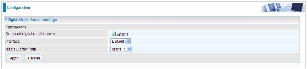
With USB storage, 8920NXL-600 can serve as a DLNA server.
On-board digital media server: Enable to share the device as a DLNA server.
Interface: The VLAN group, it is the bound interface for DLNA server accessing.
Media Library Path: Default is disk1_1, total USB space (pictures, videos, music, etc, all can be
accessed with this path).
142
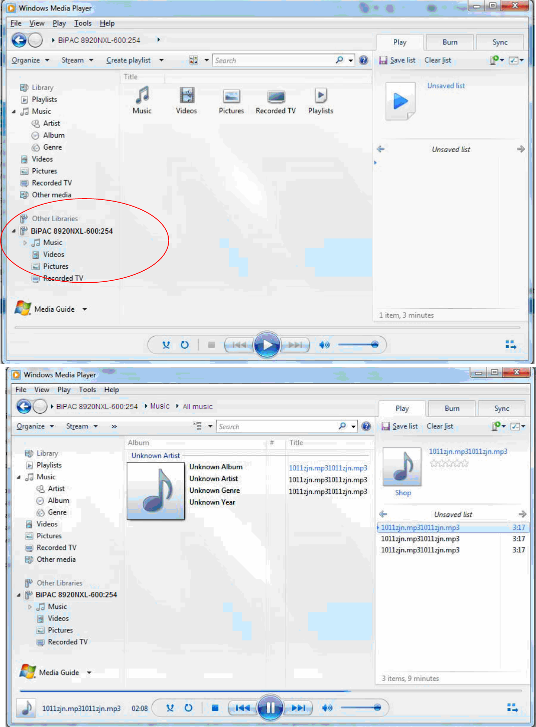
Take Windows media player in Windows 7 accessing the DLNA server for example for usage of
DLNA. The windows media player lists the resources (music, videos, etc) stored by the router’s
DLNA-based library under file “BiPAC 8920NXL-600, for example”.
143
IP Tunnel
An IP Tunnel is an Internet Protocol (IP) network communication channels between two networks of
different protocols. It is used to transport another network protocol by encapsulation of its packets.
IP Tunnels are often used to connect two disjoint IP networks that do not have a native routing path
to each other, via an underlying routable protocol across an intermediate transport network, like VPN.
Another prominent use of IP Tunnel is to connect islands of IPv6 installations across the IPv4
internet.
IPv6inIPv4
6in4 is an Internet transition mechanism for migrating from IPv4 to IPv6. 6in4 uses tunneling to
encapsulate IPv6 traffic over explicitly configured IPv4 links. The 6in4 traffic is sent over the IPv4
Internet inside IPv4 packets whose IP headers have the IP Protocol number set to 41. This protocol
number is specifically designated for IPv6 capsulation.
6RD:
6RD is a mechanism to facilitate IPv6 rapid deployment across IPv4 infrastructures of internet
service providers (ISPs).
It is derived from 6to4, a preexisting mechanism to transporting IPv6 packets over IPv4
infrastructure network, with the significant change that it operates entirely within the enduser’s ISP
network, thus avoiding the major architectural problems inherent in the original design of 6to4.
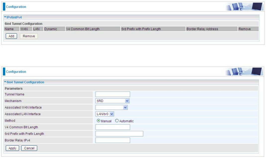
Click Add button to manually add the 6in4 rules.
Tunnel Name: User-defined name.
Mechanism: Here only 6RD.
Associated WAN Interface: The applied WAN interface with the set tunnel, thus when there are
144
packets from/to the WAN interface, the tunnel would be used to transport the packets.
Associated LAN Interface: Set the linked LAN interface with the tunnel.
Method: 6rd operation mechanism: manually configured or automatically configured. If manually,
please fill out the following 6rd parameters.
V4 Common Bit Length: Specify the length of IPv4 address carried in IPv6 prefix, for example, 0
means to carry all the 32 bits of IPv4 address while 8 carries 24 bits of the IPv4 address.
6rd Prefix with Prefix Length: Enter the 6rd prefix and prefix length you uniquely designate to 6rd
by the ISP( The 6rd prefix and prefix length are to replace the standard 6to4 prefix 2002::/16 by an
IPv6 prefix that belongs to the ISP-assigned.)
Border Relay IPv4: The IPv4 address of the border relay. The relay is used to unwrap capsulated
IPv4 packets into IPv6 packets and send them to the IPv6 network.

145
IPv4inIPv6
4in6 refers to tunneling of IPv4 in IPv6. It is an inherent internet interoperation mechanism allowing
IPv4 to be used in an IPv6 only network.
4in6 uses tunneling to encapsulate IPv4 traffic over configured IPv6 tunnels. 4in6 tunnels are usually
manually configured but they can be automated using protocols such as TSP to allow easy
connection to a tunnel broker.
DS – Lite
DS –Lite, or Dual-Stack Lite, is designed to let an ISP omit the deployment of any IPv4 address to
the customer’s CPE. Instead, only global IPv6 addresses are provided (Regular Dual-Stack Lite
deploys global addresses for both IPv4 and IPv6).
The CPE distributes private IPv4 addresses for the LAN clients, the same as a NAT device. The
subnet information is chosen by the customer, identically to the NAT model. However, instead of
performing the NAT itself, the CPE encapsulates the IPv4 packet inside an IPv6 packet.
Click Add button to manually add the 4in6 rules.
Tunnel Name: User-defined tunnel name.
Mechanism: It is the 4in6 tunnel operation technology. Please select DS-Lite.
Associated WAN Interface: The applied WAN interface with the set tunnel, and when there are
packets from/to the WAN interface, the tunnel would be used to transport the packets.
Associated LAN Interface: Specify the linked LAN interface with the tunnel.
Method: Manually to specify the AFTP (Address Family Transition Router) address or Automatic.
AFTR: Specify the address of AFTP (Address Family Transition Router) from your ISP.
146
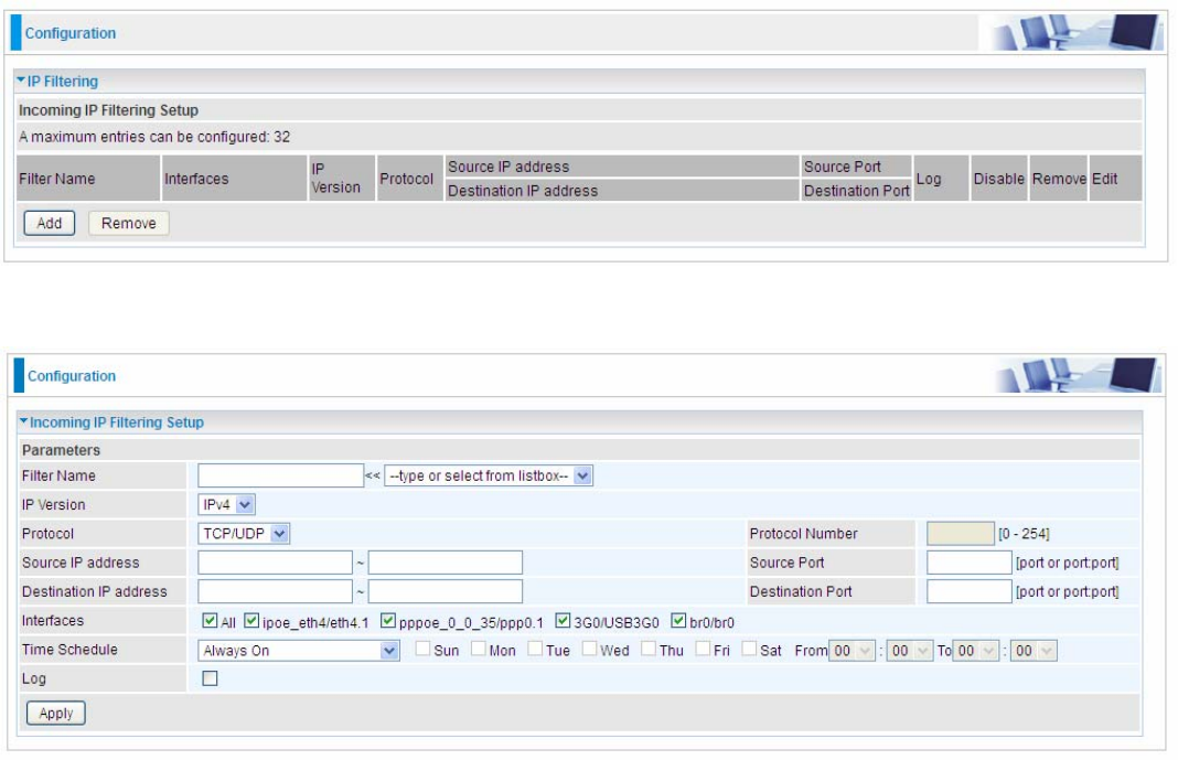
Security
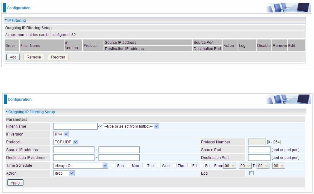
IP Filtering Outgoing
IP filtering enables you to configure your router to block specified internal/external users (IP address)
from Internet access, or you can disable specific service requests (Port number) to /from Internet.
The relationship among all filters is “or” operation, which means that the router checks these
different filter rules one by one, starting from the first rule. As long as one of the rules is satisfied, the
specified action will be taken.
Note: The maximum number of entries: 32.
Click Add button to enter the exact rule setting page.
Filter Name: A user-defined rule name. User can select simply from the list box for the application
for quick setup.
IP Version: Select the IP Version, IPv4 or IPv6.
Protocol: Set the traffic type (TCP/UDP, TCP, UDP, ICMP, RAW, Any) rule applies to.
Source IP address: This is the Address-Filter used to allow or block traffic to/from particular IP
address(es) featured in the IP range. If you leave empty, it means any IP address.
Source Port [port or port:port]: The port or port range defines traffic from the port (specific
application) or port in the set port range blocked to go through the router. Default is set port from
range 1 – 65535.
Destination IP address: Traffic from LAN with the particular traffic destination address specified in
the IP range is to be blocked from going through the router, similarly set as the Source IP address
above.
Destination Port [port or port: port]: Traffic with the particular set destination port or port in the set
port range is to be blocked from going through the router. Default is set port from port range: 1 –
147
65535.
Time Schedule: Select or set exactly when the rule works. When set to “Always On”, the rule will
work all time; and also you can set the precise time when the rule works, like 01:00 - 19:00 from
Monday to Friday. Or you can select the already set timeslot in “Time Schedule” during which the
rule works. And when set to “Disable”, the rule is disabled or inactive and there will be an icon”
” in list table indicating the rule is inactive. See Time Schedule.
Action: Select to drop or forward the packets fit the outgoing filtering rule.
Log: check the check-box to record the security log. To check the log, users can turn to Security Log.
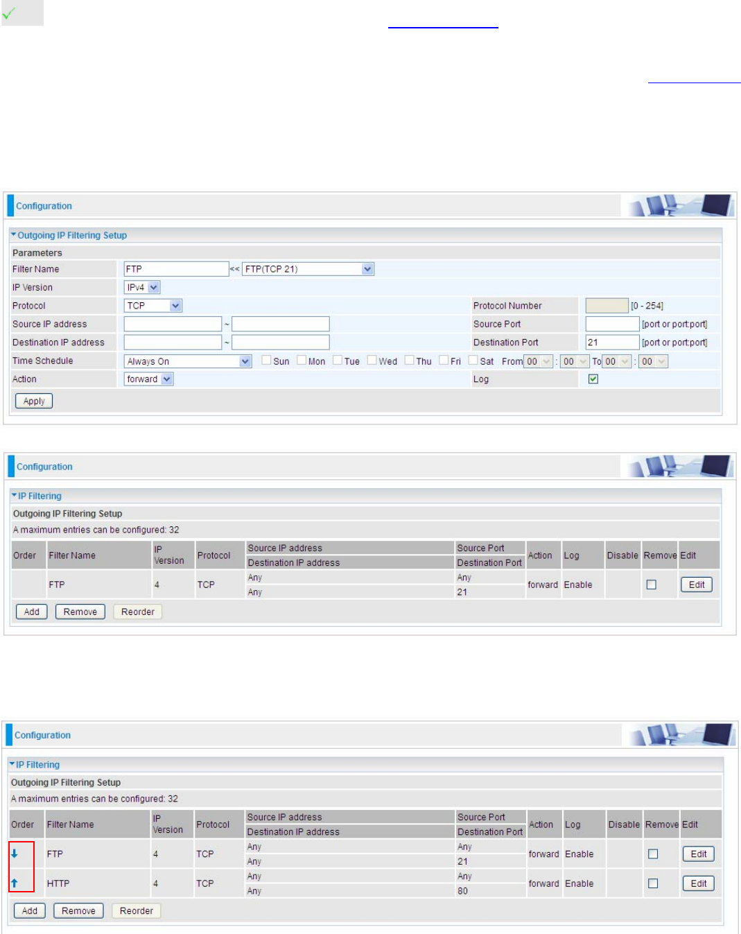
Example: For example, if there is an outgoing rule set as follows, then the 21 application between
source IP and destination IP will be blocked. Or exactly in the rule below, all traffic trying to access
FTP will be forwarded.
(The rule is active; disable field shows the status of the rule, active or inactive)
Add another Outgoing IP Filtering rule, users will find the “arrow” icon to change the IP outgoing filter
rule working orders.
148
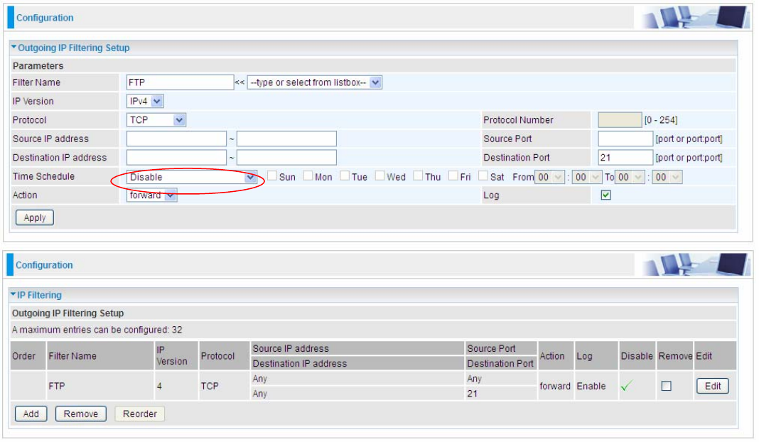
How to disable set rule.
(Rule inactive)
149
IP Filtering Incoming
Incoming IP Filtering is set by default to block all incoming traffic, but user can set rules to forward
the specific incoming traffic.
Note:
1. The maximum number of entries: 32.
2. When LAN side firewall or firewall in WAN interface(s) is enabled, user can move here to add
allowing rules to pass through the firewall.
Click Add button to enter the exact rule setting page.
Filter Name: A user-defined rule name. User can select simply from the list box for the application
for quick setup.
IP Version: Select the IP Version, IPv4 or IPv6.
Protocol: Set the traffic type (TCP/UDP, TCP, UDP, ICMP, RAW, Any ) that the rule applies to.
Source IP address: This is the Address-Filter used to allow or block traffic to/from particular IP
address(es) featured in the IP range.. If you leave empty, it means any IP address.
Source Port [port or port:port]: The port or port range defines traffic from the port (specific
application) or port in the set port range blocked to go through the router. Default is set port from
range 1 – 65535.
Destination IP address: Traffic from LAN with the particular traffic destination address specified in
the IP range is to be blocked from going through the router, similarly set as the Source IP address
above.
Destination Port [port or port : port]: Traffic with the particular set destination port or port in the
set port range is to be blocked from going through the router. Default is set port from port range: 1 –
65535
Interfaces: Check if the filter rule applies to all interfaces. User can base on need select interfaces
to make the rule take effect with those interfaces.

150
Time Schedule: Select or set exactly when the rule works. When set to “Always On”, the rule will
work all time; and also you can set the precise time when the rule works, like 01:00 - 19:00 from
Monday to Friday. Or you can select the already set timeslot in “Time Schedule” during which the
rule works. And when set to “Disable”, the rule is disabled or inactive and there will be an icon”
” in the list table indicating the rule is inactive. See Time Schedule.
Log: check the check-box to record the security log. To check the log, users can turn to Security Log.
151
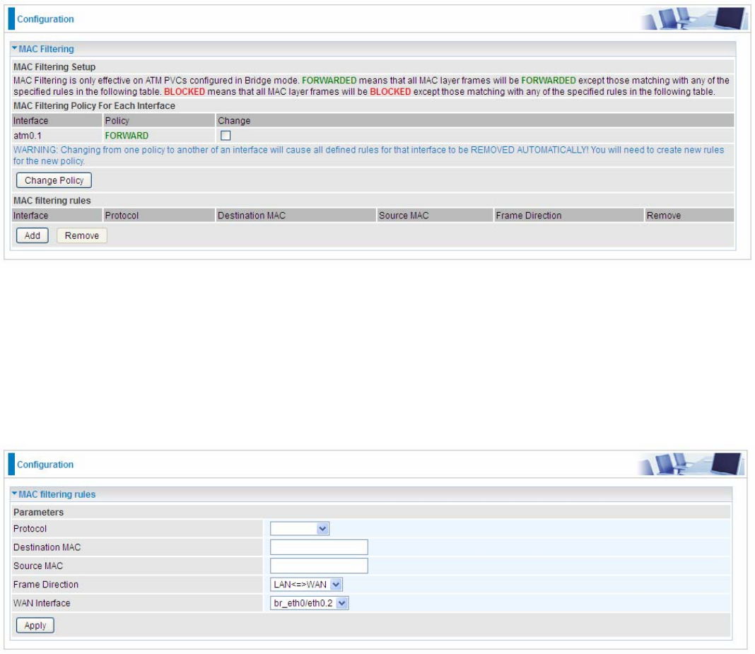
MAC Filtering
MAC Filtering is only effective on ATM PVCs configured in Bridged mode.
FORWARDED means that all MAC layer frames will be forwarded except those matching with any
of the specified rules in the following table.
BLOCKED means that all MAC layer frames will be blocked except those matching with any of the
specified rules in the following table.
By default, all MAC frames of the interface in Bridge Mode will be forwarded, you can check
Change checkbox and then press Change Policy to change the settings to the interface.
For example, from above, the interface atm0.1 is of bridge mode, and all the MAC layer frames will
be forward, but you can set some rules to let some item matched the rules to be blocked.
Click Add button to add the rules.
Protocol: Select from the drop-down menu the protocol that applies to this rule.
Destination /Source MAC Address: Enter the destination/source address.
Frame Direction: Select the frame direction this rule applies, both LAN and WAN: LAN <=>WAN,
only LAN to WAN: LAN=>WAN, only WAN to LAN: WAN=>LAN.
WAN Interfaces: Select the interfaces configured in Bridge mode.
152
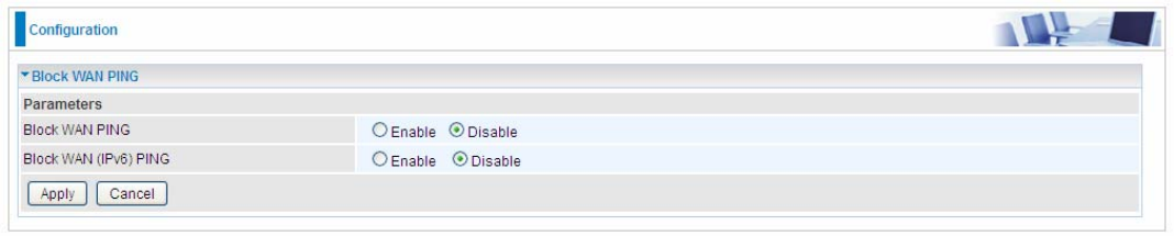
Block WAN PING
This feature is enabled to let your router not respond to any ping command when someone others
“Ping” your WAN IP.
153
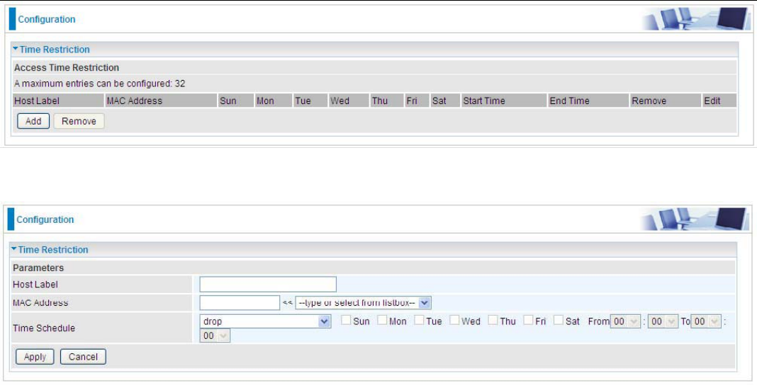
Time Restriction
A MAC (Media Access Control) address is the unique network hardware identifier for each PC on
your network’s interface (i.e. its Network Interface Card or Ethernet card). Using your router’s MAC
Address Filter function, you can configure the network to block specific machines from accessing
your LAN during the specified time.
This page adds time of day restriction to a special LAN device connected to the router. Please click
Add button to add the device(s) to be subject to Time Restriction rules (forward or drop connection to
internet). Devices Not added will not comply with the rules and access internet and router willingly.
To find out the MAC address of a window based PC, go to command window, and type “ipconfig/all”.
Note: The maximum entries configured: 32.
Click Add to add the rules.
Host Label: User-defined name.
MAC Address: Enter the MAC address(es) you want to allow or block to access the router and LAN.
The format of MAC address could be: xx:xx:xx:xx:xx:xx or xx-xx-xx-xx-xx-xx. For convenience, user
can select from the list box.
Time Schedule: Configure to control the PC from accessing router and internet.
L Drop: To drop the MAC entries always; in other words, the MACs are blocked access to router
and internet always.
L Forward: To forward the MAC entries always; in other words, the MACs are granted access to
the router and internet always.
L Check or select from listbox: To set the time duration during which the MACs are blocked
from access the router and internet. “select from listbox” means that you can select the
already set timeslot in “Time Schedule” section during which the MACs are blocked from
access the router and internet.
Click Apply to confirm your settings. The following prompt window will appear to remind you of the
attention.
154
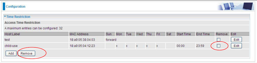
An example:
Here you can see that the user “child-use” with a MAC of 18:a9:05:04:12:23 is blocked to access the
router from 00:00 to 23:59 Monday through Friday.
The “test” can access the internet always.
If you needn’t this rule, you can check the box, press Remove, it will be OK.
.
155
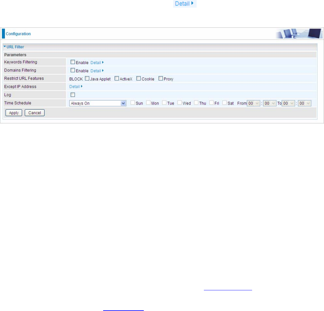
URL Filter
URL (Uniform Resource Locator – e.g. an address in the form of http://www.abcde.com or
http://www.example.com) filter rules allow you to prevent users on your network from accessing
particular websites by their URL. There are no pre-defined URL filter rules; you can add filter rules to
meet your requirements.
Note:
1) URL Filter rules apply to both IPv4 and IPv6 sources.
2) But in Exception IP Address part, user can click to set the exception IP address(es) for
IPv4 and IPv6 respectively.
Keywords Filtering: Allow blocking against specific keywords within a particular URL rather than
having to specify a complete URL (e.g.to block any image called “advertisement.gif”). When enabled,
your specified keywords list will be checked to see if any keywords are present in URLs accessed to
determine if the connection attempt should be blocked. Please note that the URL filter blocks web
browser (HTTP) connection attempts using port 80 only.
Domains Filtering: This function checks the whole URL address but not the IP address against
your list of domains to block or allow. If it is matched, the URL request will either be sent (Trusted) or
dropped (Forbidden).
Restrict URL Features: Click Block Java Applet to filter web access with Java Applet components.
Click Block ActiveX to filter web access with ActiveX components. Click Block Cookie to filter web
access with Cookie components. Click Block Proxy to filter web proxy access.
Except IP Address: You can input a list of IP addresses as the exception list for URL filtering.
These IPs will not be covered by the URL rules.
Time Schedule: Select or set exactly when the rule works. When set to “Always On”, the rule will
work all time; and also you can set the precise time when the rule works, like 01:00 - 19:00 from
Monday to Friday. Or you can select the already set timeslot in “Time Schedule” during which the
rule works. And when set to “Disable”, the rule is disabled. See Time Schedule.
Log: Select Enable for this option if you will like to capture the logs for this URL filter policy. To
check the log, users can turn to Security Log.
156
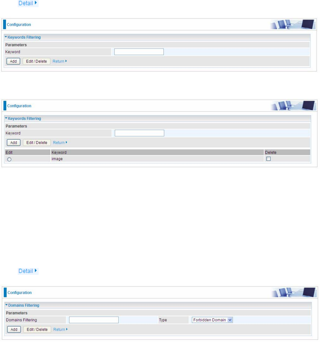
Keywords Filtering
Note: Maximum number of entries: 32.
Click to add the keywords.
Enter the Keyword, for example image, and then click Add.
You can add other keywords like this. The keywords you add will be listed as above. If you want to
reedit the keyword, press the Edit radio button left beside the item, and the word will listed in the
Keyword field, edit, and then press Edit/Delete to confirm. If you want to delete certain keyword,
check Delete checkbox right beside the item, and press Edit/Delete. Click Return to be back to the
previous page.
Domains Filtering
Note: Maximum number of entries: 32.
Click to add Domains.
Domain Filtering: enter the domain you want this filter to apply.
Type: select the action this filter deals with the Domain.
L Forbidden Domain: The domain is forbidden access.
L Trusted Domain: The domain is trusted and allowed access.
Enter a domain and select whether this domain is trusted or forbidden with the pull-down menu. Next,
click Add. Your new domain will be added to either the Trusted Domain or Forbidden Domain listing,
depending on which you selected previously. For specific process, please refer to Keywords
157
Filtering.
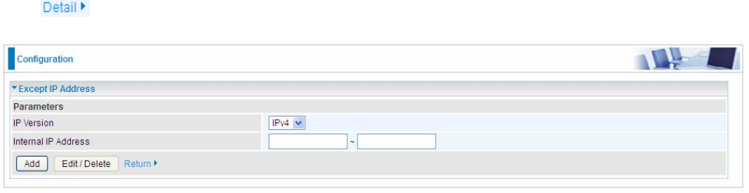
Except IP Address
In the section, users can set the exception IP respectively for IPv4 and IPv6.
Click to add the IP Addresses.
Enter the except IP address. Click Add to save your changes. The IP address will be entered into
the Exception List, and excluded from the URL filtering rules in effect. For specific process, please
refer to Keywords Filtering.
For example, users can set IPv4 client 192.168.1.103 in your network as a exception address that is
not limited to the rules set in URL filter ( or IPv4 clients (a range) ). And also an IPv6 client
(2000:1211:1002:6ba4:d160:5adb:9009:87ae) or IPv6 clients(a range ) can be the exceptions from
the URL rules.
At the URL Filter page, press Apply to confirm your settings.
158
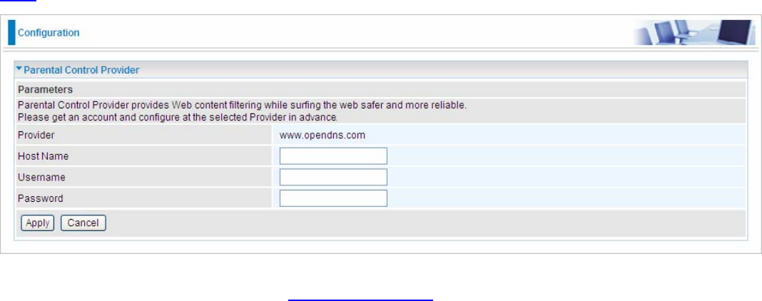
Parental Control Provider
Parental Control Provider provides Web content filtering offering safer and more reliable web surfing
for users. Please get an account and configure at the selected Provider “www.opendns.com” in
advance. To use parental control (DNS), user needs to configure to use parental control (DNS
provided by parental control provider) to access internet at WAN configuration or DNS page(See
DNS).
Host Name, Username and Password: Enter your registered domain name and your username
and password at the provider website www.opendns.com.
159
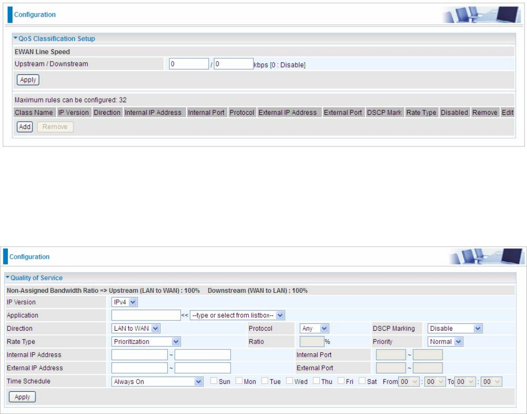
QoS - Quality of Service
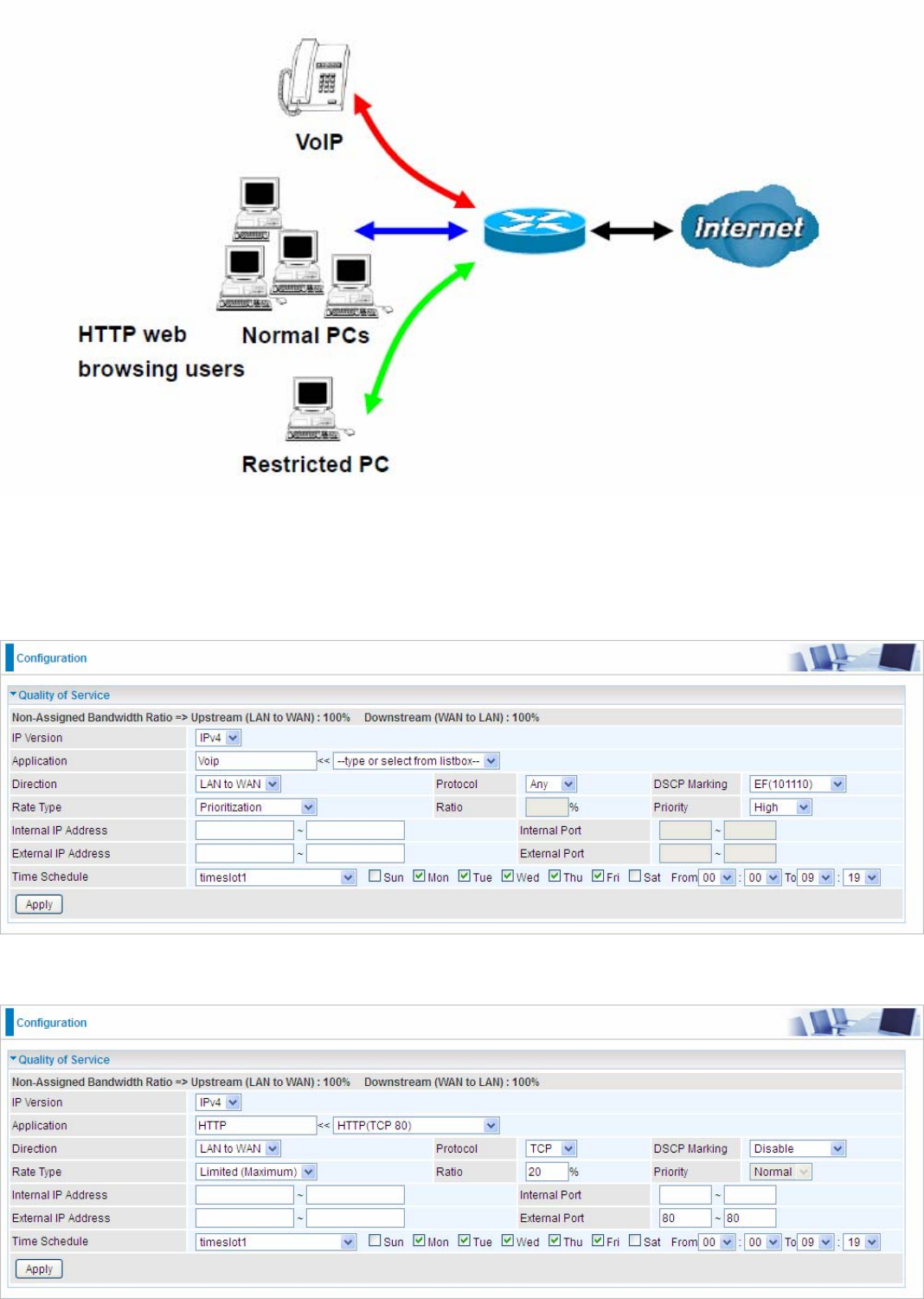
Quality of Service
QoS helps you to control the data upload traffic of each application from LAN (Ethernet) to WAN
(Internet). This feature allows you to control the quality and speed of throughput for each application
when the system is running with full upstream load.
Note: VDSL/ADSL line speed is based on the VDSL/ADSL sync rate. But there is no QoS on 3G/4G
LTE as the 3G/4G LTE line speed is various and can not be known exactly.
EWAN Line Speed
Upstream / Downstream: Specify the upstream and downstream rate of the EWAN interface.
Click Apply to save the EWAN rate settings.
Click Add to enter QoS rules.
IP Version: Select either IPv4 or IPv6 base on need.
Application: Assign a name that identifies the new QoS application rule. Select from the list box for
quick setup.
Direction: Shows the direction mode of the QoS application.
L LAN to WAN: You want to control the traffic from local network to the outside (Upstream).
You can assign the priority for the application or you can limit the rate of the application.
Eg: you have a FTP server inside the local network, and you want to have a limited control by
the QoS policy and so you need to add a policy with LAN to WAN direction setting.
L WAN to LAN: Control traffic from WAN to LAN (Downstream).

160
Protocol: Select the supported protocol from the drop down list.
DSCP Marking: Differentiated Services Code Point (DSCP), it is the first 6 bits in the ToS byte.
DSCP Marking allows users to classify the traffic of the application to be executed according to the
DSCP value.
IP Precedence and DSCP Mapping Table
Mapping Table
Default
(
000000
)
Best Effort
EF(101110) Expedited Forwarding
AF11 (001010) Assured Forwarding Class1(L)
AF12 (001100) Assured Forwarding Class1(M)
AF13 (001110) Assured Forwarding Class1(H)
AF21 (010010) Assured Forwarding Class1(L)
AF22 (010100) Assured Forwarding Class1(M)
AF23 (010110) Assured Forwarding Class1(H)
AF31 (011010) Assured Forwarding Class1(L)
AF32 (011100) Assured Forwarding Class1(M)
AF33 (011110) Assured Forwarding Class1(H)
AF41 (100010) Assured Forwarding Class1(L)
AF42 (100100) Assured Forwarding Class1(M)
AF43 (100110) Assured Forwarding Class1(H)
CS1(001000) Class Selector(IP precedence)1
CS2(010000) Class Selector(IP precedence) 2
CS3(011000) Class Selector(IP precedence)3
CS4(100000) Class Selector(IP precedence) 4
CS5(101000) Class Selector(IP precedence) 5
CS6(110000) Class Selector(IP precedence) 6
CS7(111000) Class Selector(IP precedence) 7
DSCP offers three levels of service, Class Selector (CS), Assured Forwarding (AF) and Expedited
Forwarding (EF). AF1, AF2, AF3 and AF4 are four levels of assured forwarding services. Each AF
has three different packet loss priorities from high, medium, to low. Also, CS1-CS7 indicates the IP
precedence.
Rate Type: You can choose Limited or Prioritization.
L Limited (Maximum): Specify a limited data rate for this policy. It also is the maximum rate
for this policy. When you choose Limited, type the Ratio proportion. As above FTP server
example, you may want to “throttle” the outgoing FTP speed to 20% of 256K and limit to it,
you may use this type.
L Prioritization: Specify the rate type control for the rule to used. If you choose Prioritization
for the rule, you parameter Priority would be available, you can set the priority for this rule.
L Set DSCP Marking: When select Set DSCP Marking, the packets matching the rule will be
forwarded according to the pre-set DSCP marking.
Ratio: The rate percent of each application/policy compared to total traffic on the interface with
limited rate type. For example, we want to only allow 20% of the total data for the LAN-to-WAN
direction to be used for FTP server. Then we can specify here with data ratio = 20. If you have ADSL
LINE with 256K/bps.rate, the estimated data rate, in kbps, for this rule is 20%*256*0.9 = 46kbps.
(For 0.9 is an estimated factor for the effective data transfer rate for an ADSL LINE from LAN to
WAN. For WAN-to-LAN, it is 0.85 to 0.8)
Priority: Set the priority given to each policy/application. Specify the priority for the use of bandwidth.
You can specify which application can have higher priority to acquire the bandwidth. Its default
setting is set to Normal. You may adjust this setting to fit your policy / application.

161
Internal IP Address: The IP address values for Local LAN devices you want to give control.
Internal Port: The Port number on the LAN side, it is used to identify an application.
External IP Address: The IP address on remote / WAN side.
External Port: The Port number on the remote / WAN side.
Time Schedule: Select or set exactly when the rule works. When set to “Always On”, the rule will
work all time; and also you can set the precise time when the rule works, like 01:00 - 19:00 from
Monday to Friday. Or you can select the already set timeslot in “Time Schedule” during which the
rule works. And when set to “Disable”, the rule is disabled or inactive and there will be an icon”
” indicating the rule is inactive. See Time Schedule.
162
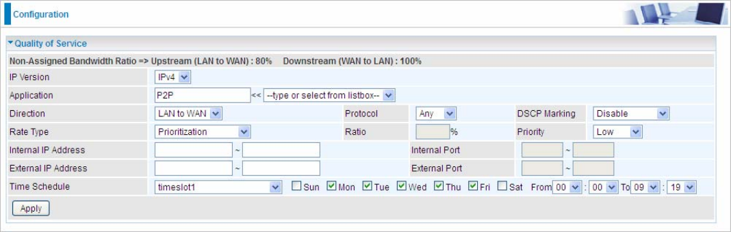
Examples: Common usage
1. Give outgoing VoIP traffic more priority.
The default queue priority is normal, so if you have VoIP users in your local network, you can set a
higher priority to the outgoing VoIP traffic.
2. Give regular web http access a limited rate
163
3. If you are actively engaged in P2P and are afraid of slowing down internet access for other users
within your network, you can then use QoS to set a rule that has low priority. In this way, P2P
application will not congest the data transmission with other applications.
Other applications, like FTP, Mail access, users can use QoS to control based on need.
164
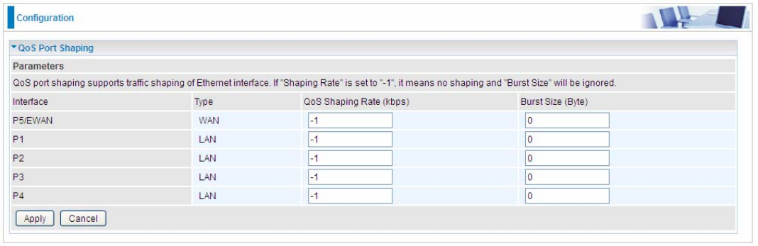
QoS Port Shaping
QoS port shaping supports traffic shaping of Ethernet interfaces. It forcefully maximizes the
throughput of the Ethernet interface. When “Shaping Rate” is set to “-1”, no shaping will be in place
and the “Burst Size” is to be ignored.
Interface: P1-P5. P5 used as EWAN also covered.
Type: All LAN when P5 is LAN port; P5 used as EWAN, type WAN and all others LAN.
QoS Shaping Rate (Kbps): Set the forcefully maximum rate.
Burst Size(Bytes): Set the forcefully Burst Size.
165
NAT
NAT (Network Address Translation) feature translates a private IP to a public IP, allowing multiple
users to access the Internet through a single IP account, sharing the single IP address. It is a natural
firewall for the private network.
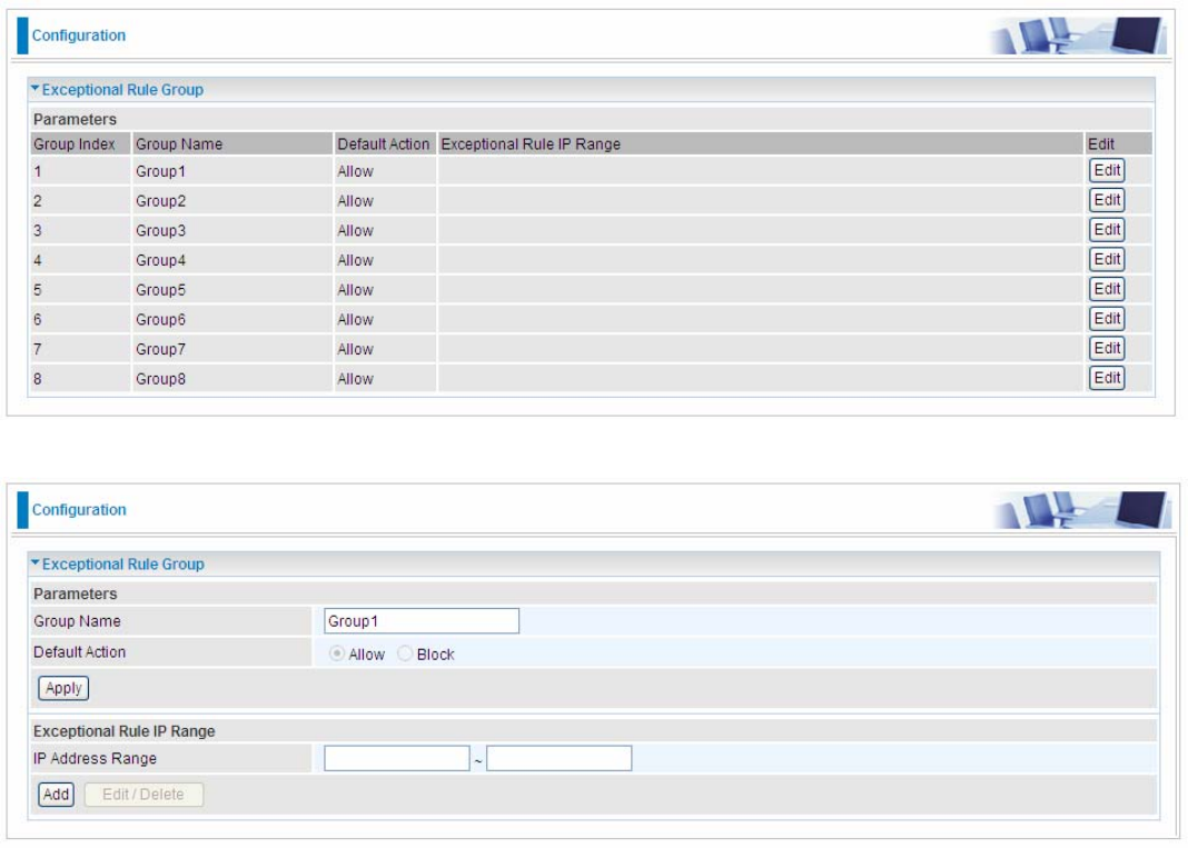
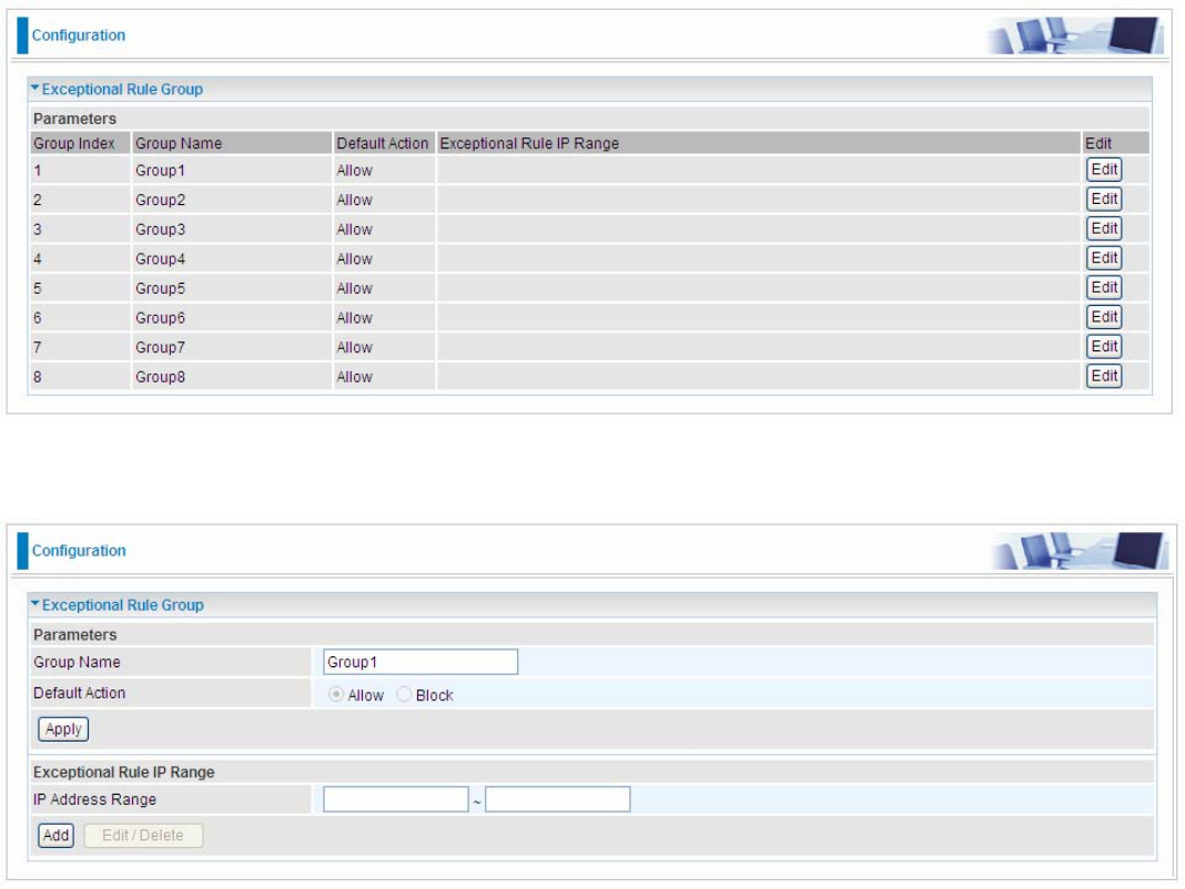
Exceptional Rule Group
Exceptional Rule is dedicated to giving or blocking NAT/DMZ access to some specific IP or
IPs(range). Users are allowed to set 8 different exceptional rule groups at most. In each group, user
can add specific IP or IP range.
Press Edit to set the exceptional IP (IP Range).
Default Action: Please first set the range to make “Default Action” setting available. Select “Allow”
to grant access to the listed IP or IPs to Virtual Server and DMZ Host.
While choose “Block” to ban the listed IP or IPs to access the Virtual Server and DMZ Host.
Apply: Press Apply button to apply the change.
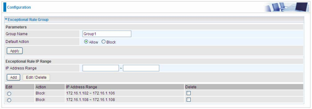
Exceptional Rule Range
IP Address Range: Specify the IP address range; IPv4 address range can be supported.
Click Add to add the IP Range.
For instance, if user wants block IP range of 172.16.1.102-172.16.1.106 from accessing your set
virtual server and DMZ host, you can add this IP range and valid it.
166
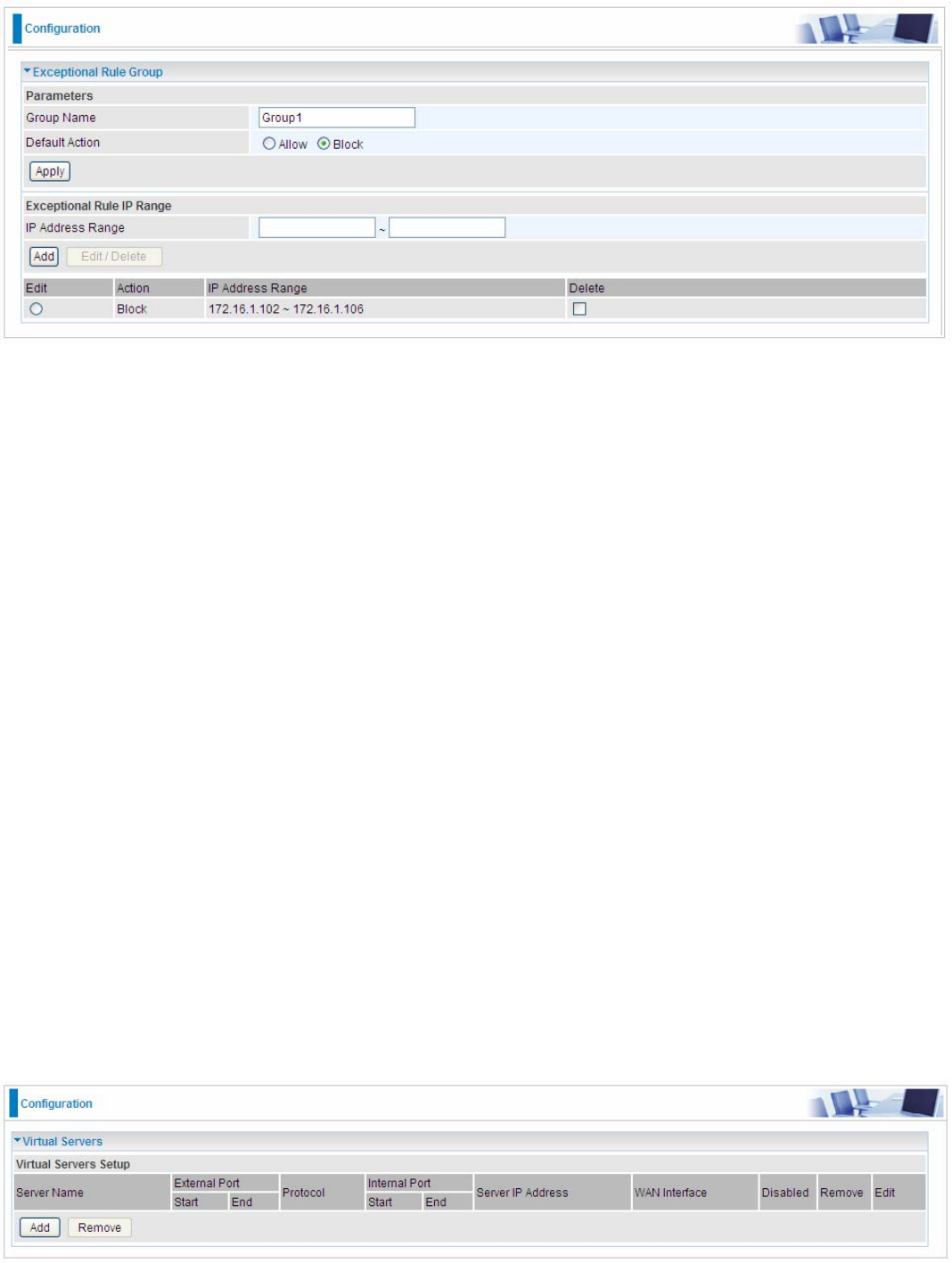
Virtual Servers
In TCP/IP and UDP networks a port is a 16-bit number used to identify which application program
(usually a server) incoming connections should be delivered to. Some ports have numbers that are
pre-assigned to them by the IANA (the Internet Assigned Numbers Authority), and these are referred
to as “well-known ports”. Servers follow the well-known port assignments so clients can locate them.
If you wish to run a server on your network that can be accessed from the WAN (i.e. from other
machines on the Internet that are outside your local network), or any application that can accept
incoming connections (e.g. Peer-to-peer/P2P software such as instant messaging applications and
P2P file-sharing applications) and are using NAT (Network Address Translation), then you will
usually need to configure your router to forward these incoming connection attempts using specific
ports to the PC on your network running the application. You will also need to use port forwarding if
you want to host an online game server.
The reason for this is that when using NAT, your publicly accessible IP address will be used by and
point to your router, which then needs to deliver all traffic to the private IP addresses used by your
PCs. Please see the WAN configuration section of this manual for more information on NAT.
The device can be configured as a virtual server so that remote users accessing services such as
Web or FTP services via the public (WAN) IP address can be automatically redirected to local
servers in the LAN network. Depending on the requested service (TCP/UDP port number), the
device redirects the external service request to the appropriate server within the LAN network.
This part is only available when NAT is enabled.
Note: The maximum number of entries: 64.
It is virtual server listing table as you see, Click Add to move on.
167
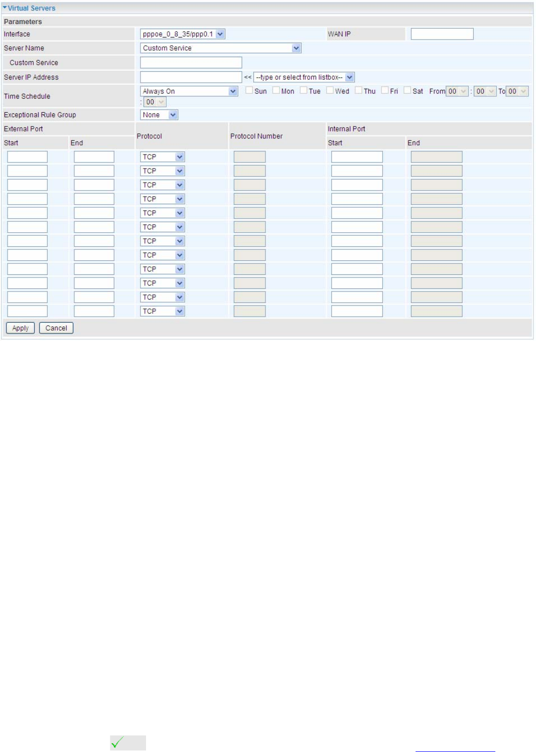
The following configuration page will appear to let you configure.
Interface: Select from the drop-down menu the interface you want the virtual server(s) to apply.
WAN IP: To specify the exact WAN IP address. It can be flexible while there are multiple WAN IPs
on one interface. If the WAN IP field is empty, 8920NXL-600 uses the current WAN IP of this
interface.
Server Name: Select the server name from the drop-down menu.
Custom Service: It is a kind of service to let users customize the service they want. Enter the user-
defined service name here. It is a parameter only available when users select Custom Service in
the above parameter.
Server IP Address: Enter your server IP Address here. User can select from the list box for quick
setup.
External Port
L Start: Enter a port number as the external starting number for the range you want to give
access to internal network.
L End: Enter a port number as the external ending number for the range you want to give
access to internal network.
Internal Port
L Start: Enter a port number as the internal staring number.
L End: Here it will generate automatically according to the End port number of External port
and can’t be modified.
Protocol: select the protocol this service used: TCP/UDP, TCP, UDP, ICMP, etc.
Time Schedule: Select or set exactly when the Virtual Server works. When set to “Always On”, the
Virtual Server will work all time; and also you can set the precise time when Virtual Server works,
like 01:00 - 19:00 from Monday to Friday. Or you can select the already set timeslot in Time
Schedule during which the Virtual Server works. And when set to “Disable”, the rule is disabled and
there will be an icon in the list table indicating the rule is disabled. See Time Schedule.
Exceptional Rule Group: Select the exceptional group listed. It is to grant or block Virtual Server
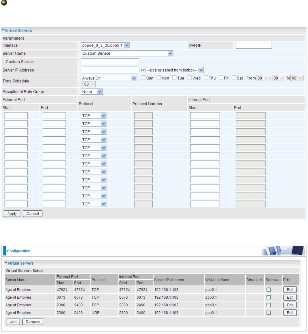
168
access to a group of IPs. For example, as we set previously group 1 blocking access to
172.16.1.102-172.16.1.106. If here you want to block Virtual Server access to this IP range, you can
select Group1.
Set up
1. Select a Server Name from the drop-down menu, then the port will automatically appear, modify
some as you like, or you can just leave it as default. Remember to enter your server IP Address.
2. Press Apply to conform, and the items will be list in the Virtual Servers Setup table.
169
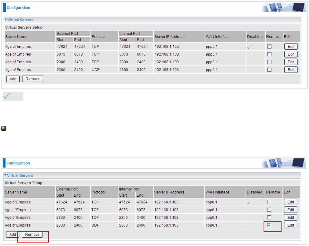
(Means the rule is inactive)
Remove
If you don’t need a specified Server, you can remove it. Check the check box beside the item you
want to remove, then press Remove, it will be OK.
170
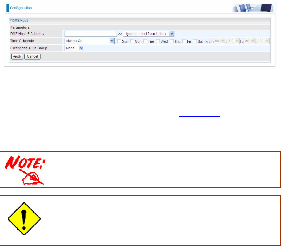
DMZ Host
The DMZ Host is a local computer exposed to the Internet. When setting a particular internal IP
address as the DMZ Host, all incoming packets will be checked by Firewall and NAT algorithms
before being passed to the DMZ host, when a packet received does not use a port number used by
any other Virtual Server entries.
DMZ Host IP Address: Enter the IP Address of a host you want it to be a DMZ host. Select from the
list box to quick set the DMZ.
Time Schedule: Select or set exactly when the DMZ works. When set to “Always On”, the DMZ will
work all time; and also you can set the precise time when DMZ works, like 01:00 - 19:00 from
Monday to Friday. Or you can select the already set timeslot in Time Schedule during which the
DMZ works. And when set to “Disable”, the rule is disabled. See Time Schedule.
Exceptional Rule Group: Select the exceptional group listed. It is to grant or block DMZ access to
a group of IPs. For example, as we set previously group 1 blocking access to 172.16.1.102-
172.16.1.106. If here you want to block DMZ Access to this IP range, you can select Group1.
Using port mapping does have security implications, since outside users are able to connect
to PCs on your network. For this reason you are advised to use specific Virtual Server
entries just for the ports your application requires instead of simply using DMZ or creating a
Virtual Server entry for “All” protocols, as doing so results in all connection attempts to your
public IP address accessing the specified PC.
Attention
If you have disabled the NAT option in the WAN-ISP section, the Virtual Server function will
hence be invalid.
If the DHCP server option is enabled, you have to be very careful in assigning the IP
addresses of the virtual servers in order to avoid conflicts. The easiest way of configuring
Virtual Servers is to manually assign static IP address to each virtual server PC, with an
address that does not fall into the range of IP addresses that are to be issued by the DHCP
server. You can configure the virtual server IP address manually, but it must still be in the
same subnet as the router.
171
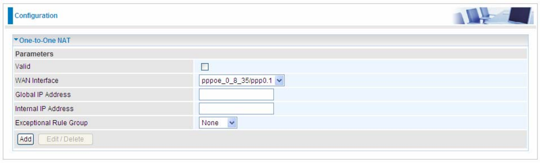
One-to-One NAT
One-to-One NAT maps a specific private/local address to a global/public IP address. If user has
multiple global/public IP addresses from your ISP, you are free to use one-to-one NAT to assign
some specific public IP for an internal IP like a public web server mapped with a global/public IP for
outside access.
Valid: Check whether to valid the one-to-one NAT mapping rule.
WAN Interface: Select one based WAN interface to configure the one-to-one NAT.
Global IP Address: The Global IP mapped to an internal device. It can be left empty, and under this
circumstance, it can be reached through the WAN IP of interface set in the field above.
Internal Address: The IP address of an internal device in the LAN.
Exceptional Rule Group: Select the exceptional group listed. It is to give or block access to a group
of IPs to the server after One-to-One NAT. For example, a server with 192.168.1.3 is mapped to
123.1.1.2 by One-to-One NAT, then the exceptional group can be designated to have or have not
access to 123.1.1.2.
For example, you have an ADSL connection of pppoe_0_8_35/ppp0.1 interface with three fixed
global IP, and you then can assign the other two global IPs to two internal devices respectively.
If you have a WEB server (IP address: 192.168.1.3) and a FTP server (IP address: 192.168.1.4) in
local network, owning a public IP address range of 123.1.1.2 to 123.1.1.4 assigned by ISP. 123.1.1.2
is used as WAN IP address of the router, 123.1.1.3 is used for WEB server and 123.1.1.4 is used for
FTP server. With One-to-One NAT, the servers with private IP addresses can be accessed at the
corresponding valid public IP addresses
172
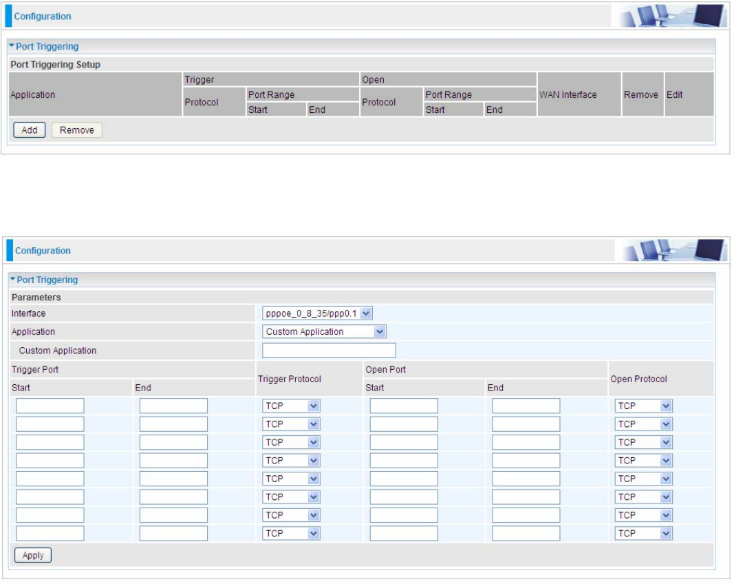
Port Triggering
Port triggering is a way to automate port forwarding with outbound traffic on predetermined ports
(‘triggering ports’), incoming ports are dynamically forwarded to the initiating host, while the
outbound ports are in use. Port triggering triggers can open an incoming port when a client on the
local network makes an outgoing connection on a predetermined port or a range of ports.
Click Add to add a port triggering rule.
Interface: Select from the drop-down menu the interface you want the port triggering rules apply to.
Application: Preinstalled applications or Custom Application user can customize the utility yourself.
Custom Application: It is a kind of service to let users themselves customizes the service they
want. Enter the user-defined service name here.
Trigger Port
L Start: Enter a port number as the triggering port starting number.
L End: Enter a port number as the triggering port ending number.
Any port in the range delimited by the ‘Start’ and ‘End’ would be the trigger port.
173
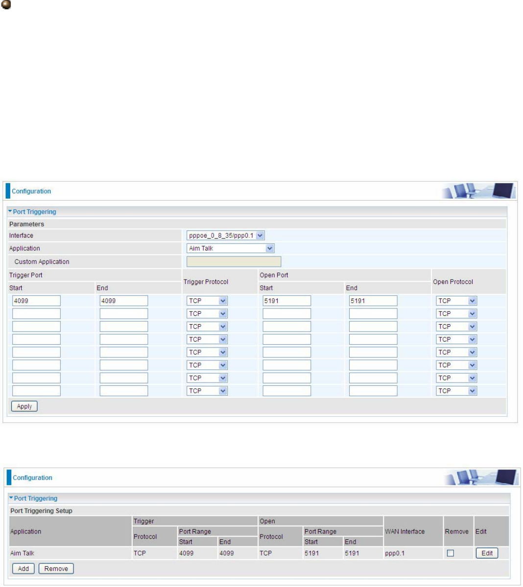
Open port
L Start: Enter a port number as the open port staring number.
L End: Enter a port number as the open port ending number.
Any port in the range delimited by the ‘Start’ and ‘End’ would be the preset forwarding port or open
port.
Protocol: select the protocol this service used: TCP/UDP, TCP, UDP.
Set up
An example of how port triggering works, when a client behind a NAT router connecting to Aim Talk,
it is a TCP connection with the default port 4099.
When connecting to Aim Talk, the client typically makes an outgoing connection on port 4099 to the
Aim Talk server, but when the computer is behind the NAT, the NAT silently drops this connection
because it does not know which computer behind the NAT to send the request to connect.
So, in this case, port triggering in the router is working, when an outbound connection is attempted
on port 4099 (or any port in the range set), it should allow inbound connections to that particular
computer.
1. Select a Server Name from the drop-down menu, then the port will automatically appear, modify
some as you like, or you can just leave it as default. Remember to enter your server IP Address.
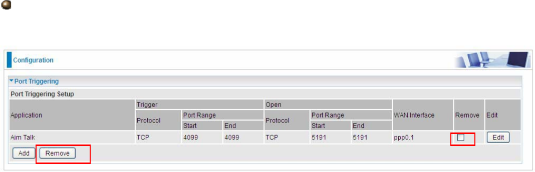
2. Press Apply to conform, and the items will be list in the Port Triggering Setup table.
174
Remove
If you don’t need a specified Server, you can remove it. Check the check box beside the item you
want to remove, and then press Remove.
175
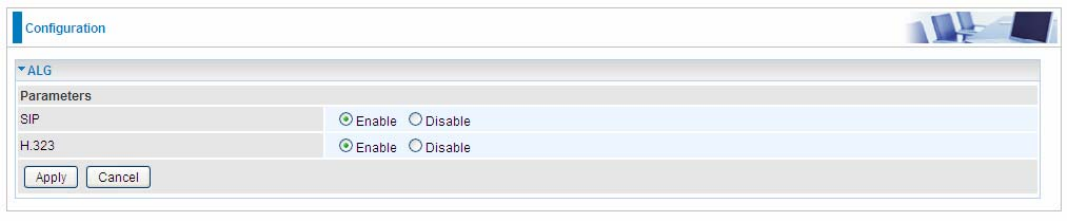
ALG
The ALG Controls enable or disable protocols over application layer.
SIP: Enable the SIP ALG when SIP phone needs ALG to pass through the NAT. Disable the SIP
when SIP phone includes NAT-Traversal algorithm.
H.323: Enable to secure the voice communication using H.323 protocol when one or both terminals
are behind a NAT.
176
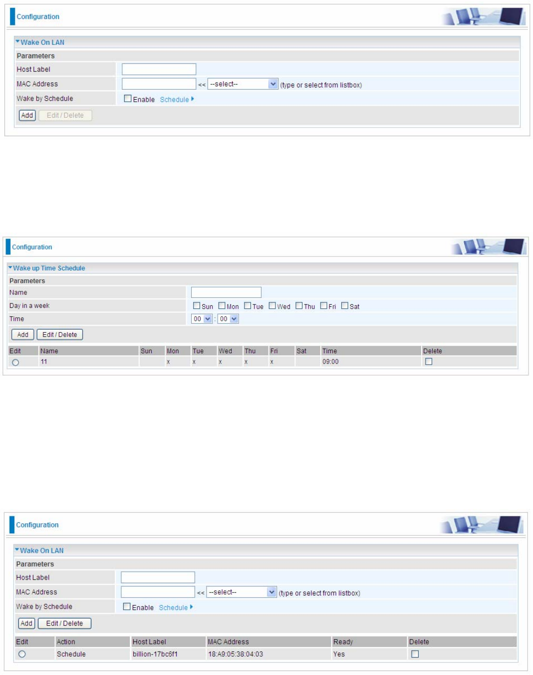
Wake On LAN
Wake on LAN (WOL, sometimes WoL) is an Ethernet computer networking standard that allows a
computer to be turned on or woken up remotely by a network message.
Host Label: Enter identification for the host.
MAC Address: Select MAC address of the computer that you want to wake up or turn on remotely.
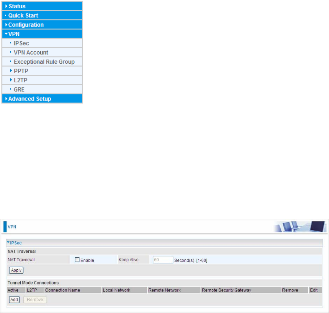
Wake by Schedule: Enable to wake up your set device at some specific time. For instance, user
can set to get some device woken up at 8:00 every weekday. Click Schedule to enter time schedule
configuring page to set the exact timeline.
Add: After selecting, click Add then you can submit the Wake-up action.
Edit/Delete: Click to edit or delete the selected MAC address.
Ready:
“Yes” indicating the remote computer is ready for your waking up.
“No” indicating the machine is not ready for your waking up.
Delete: Delete the selected MAC address.
177
VPN(BiPAC 8920NX-600 only)
A virtual private network (VPN) is a private network that interconnects remote (and often
geographically separate) networks through primarily public communication infrastructures such as
the Internet. VPNs provide security through 2222tunneling protocols and security procedures such as
2222encryption. For example, a VPN could be used to securely connect the branch offices of an
organization to a head office network through the public Internet.
IPSec
Internet Protocol Security (IPsec) is a 2222protocol suite for securing 2222Internet Protocol (IP)
communications by 2222authenticating and 2222encrypting each 2222IP packet of a communication session. IPsec
also includes protocols for establishing 2222mutual authentication between agents at the beginning of the
session and negotiation of 2222cryptographic keys to be used during the session.
IPsec is an end-to-end security scheme operating in the 2222Internet Layer of the 2222Internet Protocol Suite.
It can be used in protecting data flows between a pair of security gateways (network-to-network), or
between a security gateway and a host (network-to-host).
Note: A maximum of 16 sessions for IPSec.
NAT Traversal
NAT Traversal: This directive enables use of the NAT-Traversal IPsec extension (NAT-T). NAT-T
allows one or both peers to reside behind a NAT gateway (i.e., doing address- or port-translation).
Keep Alive: Type the interval time(sec) for sending packets to keep the NAT Traversal alive.
Click Apply to save and apply your settings.
178
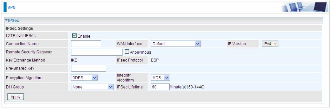
Click Add to create IPSec connections.
IPSec Settings
L2TP over IPSec: Select Enable if user wants to use L2TP over IPSec. See 2222L2TPover IPSec
Connection Name: A given name for the connection, but it should contain no spaces (e.g.
“connection-to-office”).
WAN Interface: Select the set used interface for the IPSec connection, when you select adsl
pppoe_0_0_35/ppp0.1 interface, the IPSec tunnel would transmit data via this interface to connect to
the remote peer.
IP Version: Select the IP version base on your network framework.
Local Network: Set the IP address or subnet of the local network.
L Single Address: The IP address of the local host, for establishing an IPSec
connection between a security gateway and a host (network-to-host).
L Subnet: The subnet of the local network, for establishing an IPSec tunnel between a
pair of security gateways (network-to-network)
IP Address: The local network address.
Netmask: The local network netmask.
Remote Security Gateway: The IP address of the remote VPN device that is connected and
establishes a VPN tunnel.
Anonymous: Enable any IP to connect in.
Remote Network: Set the IP address or subnet of the remote network.
L Single Address: The IP address of the local host, for establishing an IPSec
connection between a security gateway and a host (network-to-host). If the remote
peer is a host, select Single Address.
L Subnet: The subnet of the local network, for establishing an IPSec tunnel between a
pair of security gateways (network-to-network), If the remote peer is a network, select
Subnet.
179
Key Exchange Method: Displays key exchange method.
Pre-Shared Key: This is for the Internet Key Exchange (IKE) protocol, a string from 1 to 32
characters. Both sides should use the same key. IKE is used to establish a shared security policy
and authenticated keys for services (such as IPSec) that require a key. Before any IPSec traffic can
be passed, each router must be able to verify the identity of its peer. This can be done by manually
entering the pre-shared key into both sides (router or hosts).
Local ID Type and Remote ID Type: When the mode of phase 1 is aggressive, Local and Remote
peers can be identified by other IDs.
ID content: Enter ID content the name you want to identify when the Local and Remote Type are
Domain Name; Enter ID content IP address you want to identify when the Local and Remote Type
are IP addresses (IPv4 and IPv6 supported).
Phase 1
Mode: Select IKE mode from the drop-down menu: Main or Aggressive. This IKE provides
secured key generation and key management.
Encryption Algorithm: Select the encryption algorithm from the drop-down menu. There are
several options: 3DES and AES (128, 192 and 256). 3DES and AES are more powerful but
increase latency.
L DES: Stands for Triple Data Encryption Standard, it uses 56 bits as an encryption method.
L 3DES: Stands for Triple Data Encryption Standard, it uses 168 (56*3) bits as an encryption
method.
L AES: Stands for Advanced Encryption Standards, you can use 128, 192 or 256 bits as
encryption method.
Integrity Algorithm: Authentication establishes the integrity of the datagram and ensures it is not
tampered with in transmit. There are 2 options: Message Digest 5 (MD5) and Secure Hash
Algorithm (SHA1). SHA1 is more resistant to brute-force attacks than MD5. However, it is slower.
L MD5: A one-way hashing algorithm that produces a 128−bit hash.
L SHA1: A one-way hashing algorithm that produces a 160−bit hash.
DH Group: It is a public-key cryptography protocol that allows two parties to establish a shared
secret over an unsecured communication channel (i.e. over the Internet). MODP stands for Modular
Exponentiation Groups.
SA Lifetime: Specify the number of minutes that a Security Association (SA) will stay active before
new encryption and authentication key will be exchanged. Enter a value to issue an initial
connection request for a new VPN tunnel. Default is 480 minutes (28800 seconds). A short SA time
increases security by forcing the two parties to update the keys. However, every time when the VPN
tunnel re-negotiates, access through the tunnel will be temporarily disconnected.
Phase 2
Encryption Algorithm: Select the encryption algorithm from the drop-down menu. There are
several options: 3DES and AES (128, 192 and 256). 3DES and AES are more powerful but
increase latency.
Integrity Algorithm: Authentication establishes the integrity of the datagram and ensures it is not
tampered with in transmit. There are 2 options: Message Digest 5 (MD5) and Secure Hash
Algorithm (SHA1). SHA1 is more resistant to brute-force attacks than MD5. However, it is slower.
DH Group: It is a public-key cryptography protocol that allows two parties to establish a shared
secret over an unsecured communication channel (i.e. over the Internet). MODP stands for Modular
Exponentiation Groups.
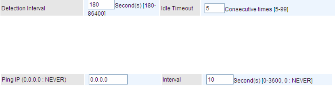
180
IPSec Lifetime: Specify the number of minutes that IPSec will stay active before new encryption
and authentication key will be exchanged. Enter a value to negotiate and establish secure
authentication. Default is 60 minutes (3600 seconds). A short time increases security by forcing the
two parties to update the keys. However, every time when the VPN tunnel re- negotiates, access
through the tunnel will be temporarily disconnected.
Ping for Keep Alive: Select the operation methods:
L None: The default setting is “None”. To this mode, it will not detect the remote IPSec peer
has been lost or not. It only follows the policy of Disconnection time after no traffic, which the
remote IPSec will be disconnected after the time you set in this function.
L DPD: Dead peer detection (DPD) is a keeping alive mechanism that enables the router to be
detected lively when the connection between the router and a remote IPSec peer has lost.
Please be noted, it must be enabled on the both sites.
Detection Interval: The period cycle for dead peer detection. The interval can be 180~86400
seconds.
Idle Timeout: Auto-disconnect the IPSec connection after trying several consecutive times.
L Ping: This mode will detect whether the remote IPSec peer has lost or not by pinging specify IP
address.
Ping IP: Type the IP for ping operation. It is able to IP Ping the remote PC with the specified IP
address and alert when the connection fails. Once alter message is received, Router will drop this
tunnel connection. Reestablish of this connection is required. Default setting is 0.0.0.0 which
disables the function.
Interval: This sets the time interval between Pings to the IP function to monitor the connection
status. Default interval setting is 10 seconds. Time interval can be set from 0 to 3600 second, 0
second disables the function.
MTU: Maximum Transmission Unit, maximum value is 1500.
181
IPSec for L2TP
Connection Name: A given name for the connection, but it should contain no spaces (e.g.
“connection-to-office”).
WAN Interface: Select the set interface for the IPSec tunnel.
Remote Security Gateway: Input the IP of remote security gateway.
Key Exchange Method: Displays key exchange method.
Pre-Shared Key: This is for the Internet Key Exchange (IKE) protocol, a string from 1 to 32
characters. Both sides should use the same key. IKE is used to establish a shared security policy
and authenticated keys for services (such as IPSec) that require a key. Before any IPSec traffic can
be passed, each router must be able to verify the identity of its peer. This can be done by manually
entering the pre-shared key into both sides (router or hosts).
Encryption Algorithm: Select the encryption algorithm from the drop-down menu. There are
several options: 3DES and AES (128, 192 and 256). 3DES and AES are more powerful but
increase latency.
L 3DES: Stands for Triple Data Encryption Standard, it uses 168 (56*3) bits as an encryption
method.
L AES: Stands for Advanced Encryption Standards, you can use 128, 192 or 256 bits as
encryption method.
Integrity Algorithm: Authentication establishes the integrity of the datagram and ensures it is not
tampered with in transmit. There are 2 options: Message Digest 5 (MD5) and Secure Hash
Algorithm (SHA1). SHA1 is more resistant to brute-force attacks than MD5. However, it is slower.
L MD5: A one-way hashing algorithm that produces a 128−bit hash.
L SHA1: A one-way hashing algorithm that produces a 160−bit hash.
DH Group: It is a public-key cryptography protocol that allows two parties to establish a shared
secret over an unsecured communication channel (i.e. over the Internet). MODP stands for Modular
Exponentiation Groups.
IPSec Lifetime: Specify the number of minutes that IPSec will stay active before new encryption
and authentication key will be exchanged. Enter a value to negotiate and establish secure
authentication. Default is 60 minutes (3600 seconds). A short time increases security by forcing the
two parties to update the keys. However, every time when the VPN tunnel re- negotiates, access
through the tunnel will be temporarily disconnected.
182
Examples:
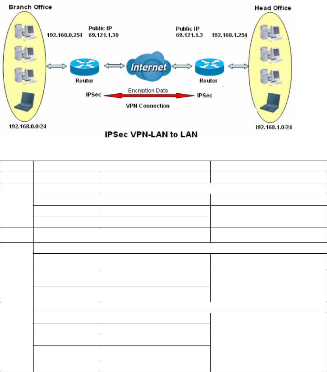
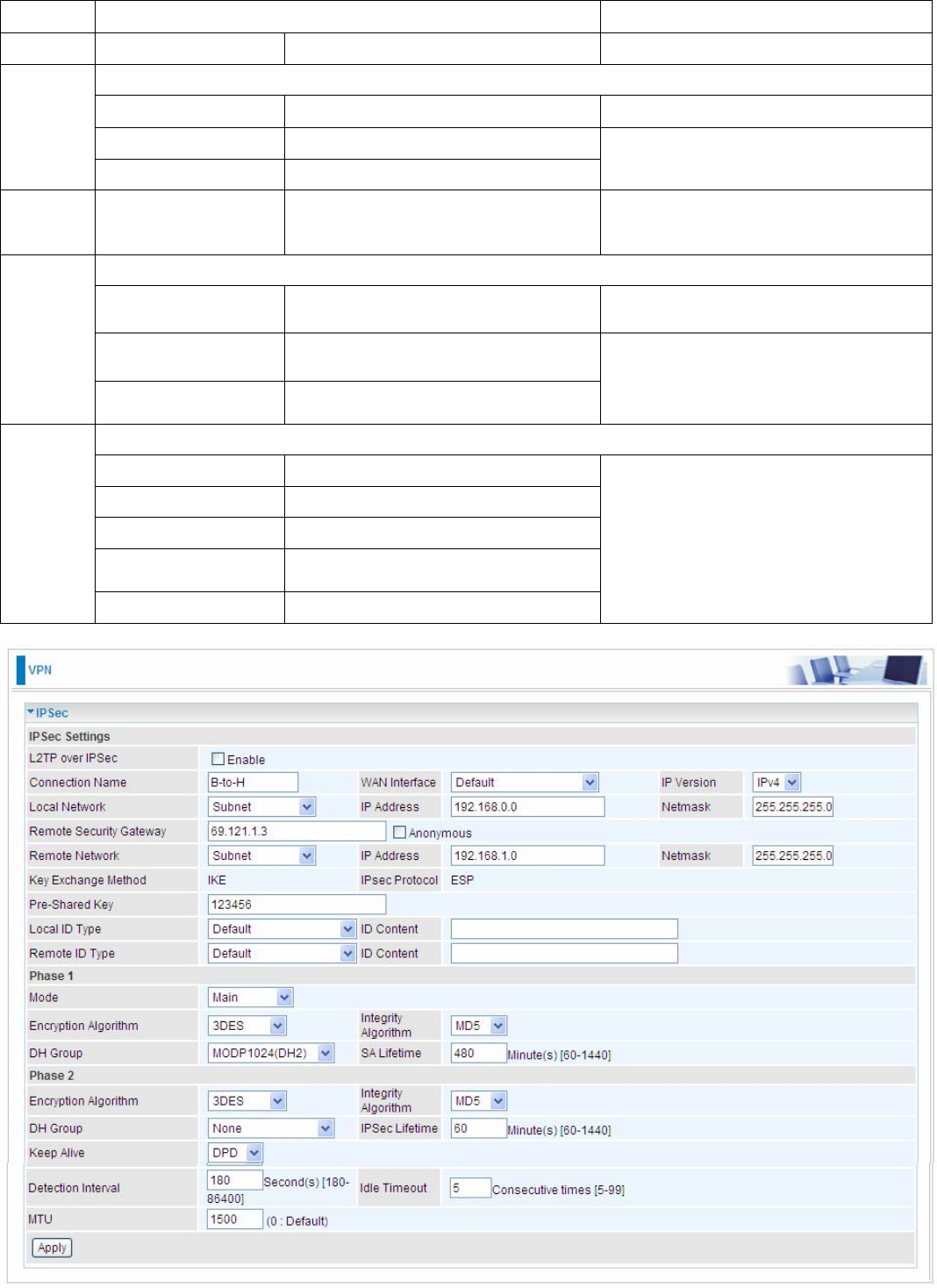
1. LAN-to-LAN connection
Two BiPAC 89200NX-600s want to setup a secure IPSec VPN tunnel
Note: The IPSec Settings shall be consistent between the two routers.
Head Office Side:
Setup details:
Item Function
Description
1 Connection Name H-to-B Give a name for IPSec connection
Local Network
Subnet Select Subnet
IP Address 192.168.1.0
2
Netmask 255.255.255.0 Head Office network
3 Secure Gateway
Address(Hostanme) 69.121.1.30 IP address of the Branch office router
(on WAN side)
Remote Network
Subnet Select Subnet
IP Address 192.168.0.0
4
Netmask 255.255.255.0
Branch office network
Proposal
Method ESP
Authentication MD5
Encryption 3DES
Prefer Forward
Security MODP 1024(group2)
5
Pre-shared Key 123456
Security Plan
183
184
Branch Office Side:
Setup details: the same operation as done in Head Office side
Item Function Description
1 Connection Name B-to-H Give a name for IPSec connection
Local Network
Subnet Select Subnet
IP Address 192.168.0.0
2
Netmask 255.255.255.0 Branch Office network
3
Remote Secure
Gateway
Address(Hostanme)
69.121.1.3 IP address of the Head office router
(on WAN side)
Remote Network
Subnet Select Subnet
IP Address 192.168.1.0
4
Netmask 255.255.255.0
Head office network
Proposal
Method ESP
Authentication MD5
Encryption 3DES
Prefer Forward
Security MODP 1024(group2)
5
Pre-shared Key 123456
Security Plan
185
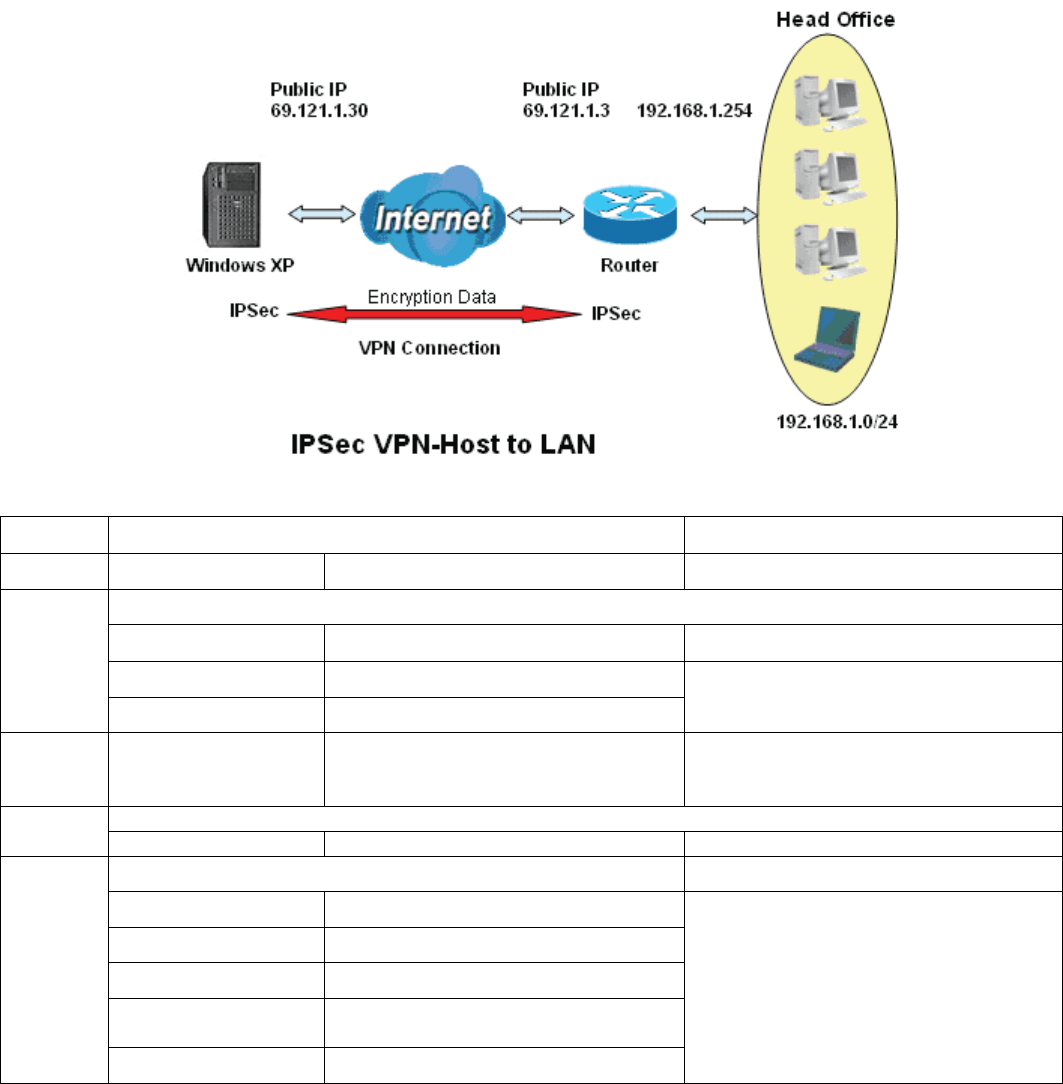
1. Host to LAN
Router servers as VPN server, and host should install the IPSec client to connect to head office
through IPSec VPN.
Item Function
Description
1 Connection Name
Headoffice-to-Host Give a name for IPSec connection
Local Network
Subnet Select Subnet
IP Address 192.168.1.0
2
Netmask 255.255.255.0 Head Office network
3
Remote Secure
Gateway
(Hostanme)
69.121.1.30 IP address of the Branch office router
(on WAN side)
Remote Network
4 Single Address 69.121.1.30 Host
Proposal
Method ESP
Authentication MD5
Encryption 3DES
Prefer Forward
Security MODP 1024(group2)
5
Pre-shared Key 123456
Security Plan

186
187
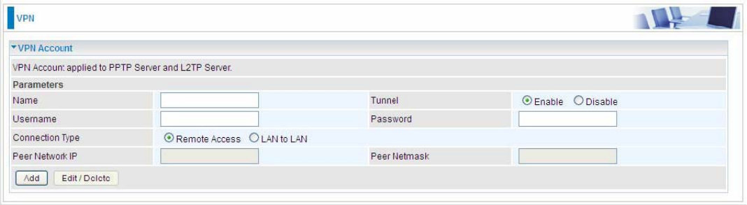
VPN Account
PPTP and L2TP server share the same account database set in VPN Account page.
Name: A user-defined name for the connection.
Tunnel: Select Enable to activate the account. PPTP(L2TP) server is waiting for the client to
connect to this account.
Username: Please input the username for this account.
Password: Please input the password for this account.
Connection Type: Select Remote Access for single user, Select LAN to LAN for remote gateway.
Peer Network IP: Please input the subnet IP for remote network.
Peer Netmask: Please input the Netmask for remote network.
188
Exceptional Rule Group
Exceptional Rule is dedicated to giving or blocking PPTP/L2TP server access to some specific IP or
IPs(range). Users are allowed to set 8 different exceptional rule groups at most. In each group, user
can add specific IP or IP range.
Press Edit to set the exceptional IP (IP Range).
Default Action: Please first set the range to make “Default Action” setting available. Set “Allow” to
ban the listed IP or IPs to access the PPTP and L2TP server.
Check “Block” to grant access to the listed IP or IPs to the PPTP and L2TP server.
Apply: Press Apply button to apply the change.
189
Exceptional Rule Range
IP Address Range: Specify the IP address range; IPv4 address range can be supported.
Click Add to add the IP Range.
For instance, if user wants to block IP range of 172.16.1.102-172.16.1.106 from accessing your
PPTP and L2TP server, you can add this IP range and valid it.
190
PPTP
The Point-to-Point Tunneling Protocol (PPTP) is a Layer2 tunneling protocol for implementing
virtual private networks through IP network. PPTP uses an enhanced GRE (Generic Routing
Encapsulation) mechanism to provide a flow- and congestion-controlled encapsulated datagram
service for carrying PPP packets.
In the Microsoft implementation, the tunneled PPP traffic can be authenticated with 2222PAP, 2222CHAP,
2222Microsoft CHAP V1/V2 or 2222EAP-TLS. The PPP payload is encrypted using 2222Microsoft Point-to-Point
Encryption (MPPE) when using MSCHAPv1/v2 or EAP-TLS.
Note: 4 sessions for Client and 4 sessions for Server respectively.
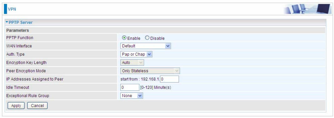
PPTP Server
In PPTP session, users can set the basaic parameters(authentication, encyption, peer address, etc)
for PPTP Server, and accounts in the next page of PPTP Account. They both constitutes the PPTP
Server setting.
PPTP Funtion: Select Enable to activate PPTP Server. Disable to deactivate PPTP Server function.
WAN Interface: Select the exact WAN interface configured for the tunnel. Select Default to use the
now-working WAN interface for the tunnel.
Auth. Type: The authentication type, Pap or Chap, PaP, Chap and MS-CHAPv2. When using PAP,
the password is sent unencrypted, whilst CHAP encrypts the password before sending, and also
allows for challenges at different periods to ensure that an intruder has not replaced the client. When
passed the authentication with MS-CHAPv2, the MPPE encryption is supported.
Encryption Key Length: The data can be encrypted by MPPE algorithm with 40 bits or 128 bits.
Default is Auto, it is negotiated when establishing a connection. 128 bit keys provide stronger
encryption than 40 bit keys.
Peer Encryption Mode: You may select “Only Stateless” or “Allow Stateless and Stateful” mode.
The key will be changed every packet when you select Stateless mode.
IP Addresses Assigned to Peer: 192.168.1.x: please input the IP assigned range from 1~ 254.
Idle Timeout: Specify the time for remote peer to be disconnected without any activities, from 0~120
191
minutes.
Exceptional Rule Group: Select to grant or block access to a group of IPs to the PPTP server. See
2222Exceptional Rule Group. If there is not any restriction, select none.
Click Apply to submit your PPTP Server basic settings.
PPTP Client
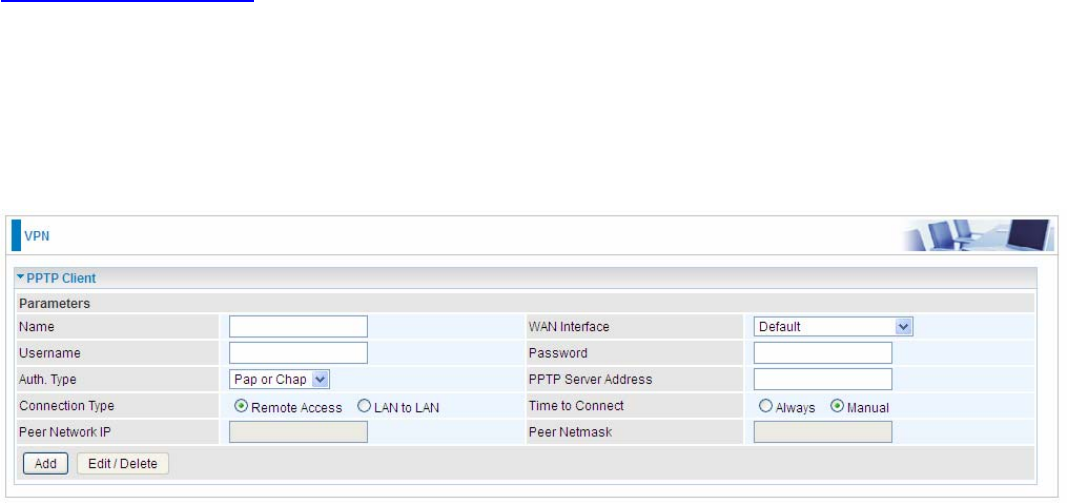
PPTP client can help you dial-in the PPTP server to establish PPTP tunnel over Internet.
Name: user-defined name for identification.
WAN Interface: Select the exact WAN interface configured for the tunnel. Select Default to use the
now-working WAN interface for the tunnel.
Username: Enter the username provided by your VPN Server.
Password: Enter the password provided by your VPN Server.
Auth. Type: Default is Auto if you want the router to determine the authentication type to use, or
else manually specify CHAP (Challenge Handshake Authentication Protocol) or PAP (Password
Authentication Protocol) if you know which type the server is using (when acting as a client), or else
the authentication type you want clients connecting to you to use (when acting as a server). When
using PAP, the password is sent unencrypted, whilst CHAP encrypts the password before sending,
and also allows for challenges at different periods to ensure that an intruder has not replaced the
client.
PPTP Server Address: Enter the IP address of the PPTP server.
Connection Type: Select Remote Access for single user, Select LAN to LAN for remote gateway.
Time to Connect: Select Always to keep the connection always on, or Manual to connect manually
any time.
Peer Network IP: Please input the subnet IP for Server peer.
Peer Netmask: Please input the Netmask for server peer.
Click Add button to save your changes.
192
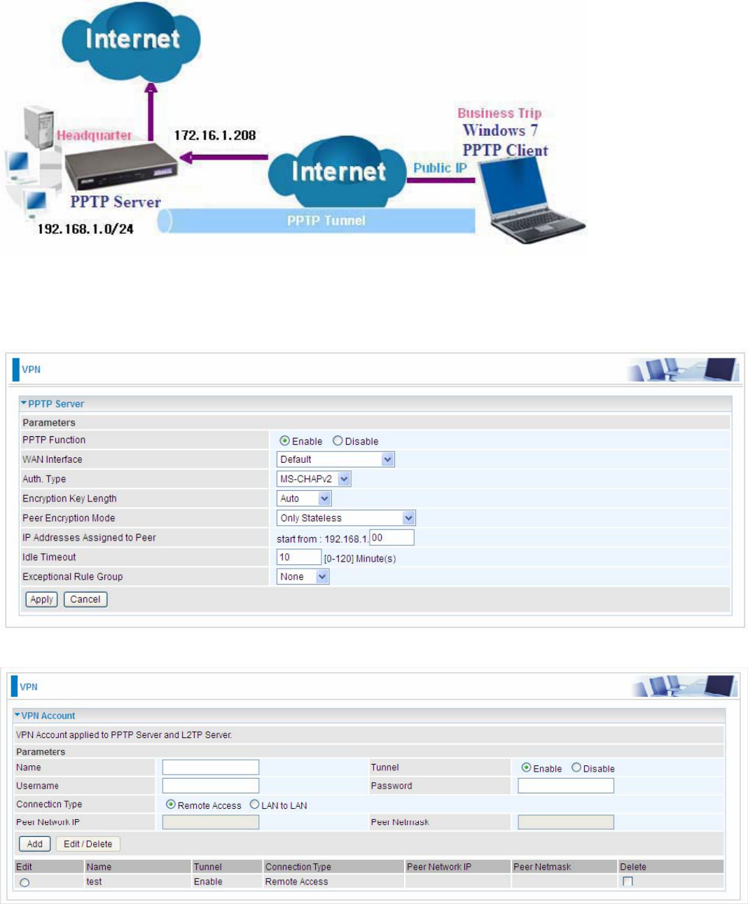
Example: PPTP Remote Access with Windows7
(Note: inside test with 172.16.1.208, just an example for illustration)
Server Side:
1. Configuration > VPN > PPTP and Enable the PPTP function, Click Apply.
2. Create a PPTP Account “test”.
193
Client Side:
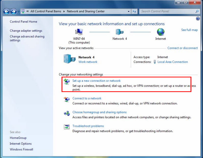
1. In Windows7 click Start > Control Panel> Network and Sharing Center, Click Set up a new
connection network.
194
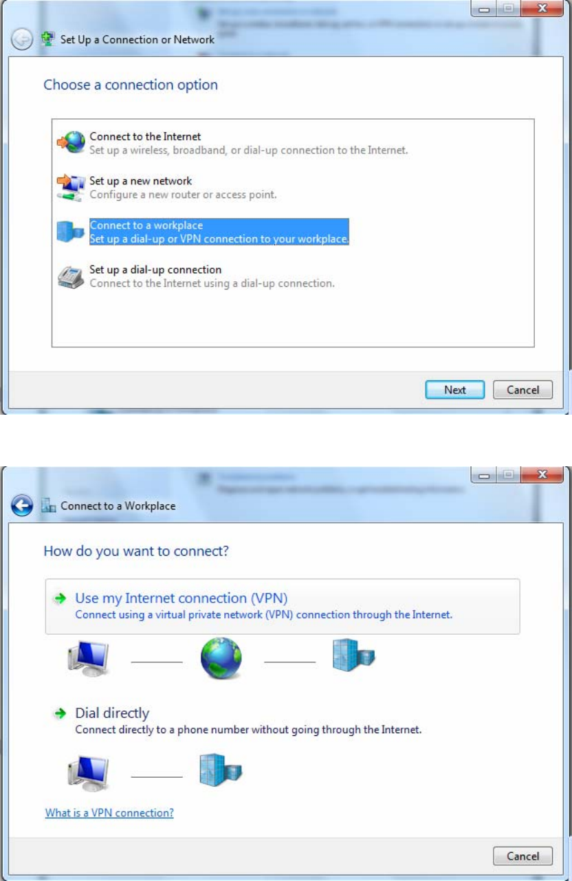
2. Click Connect to a workplace, and press Next.
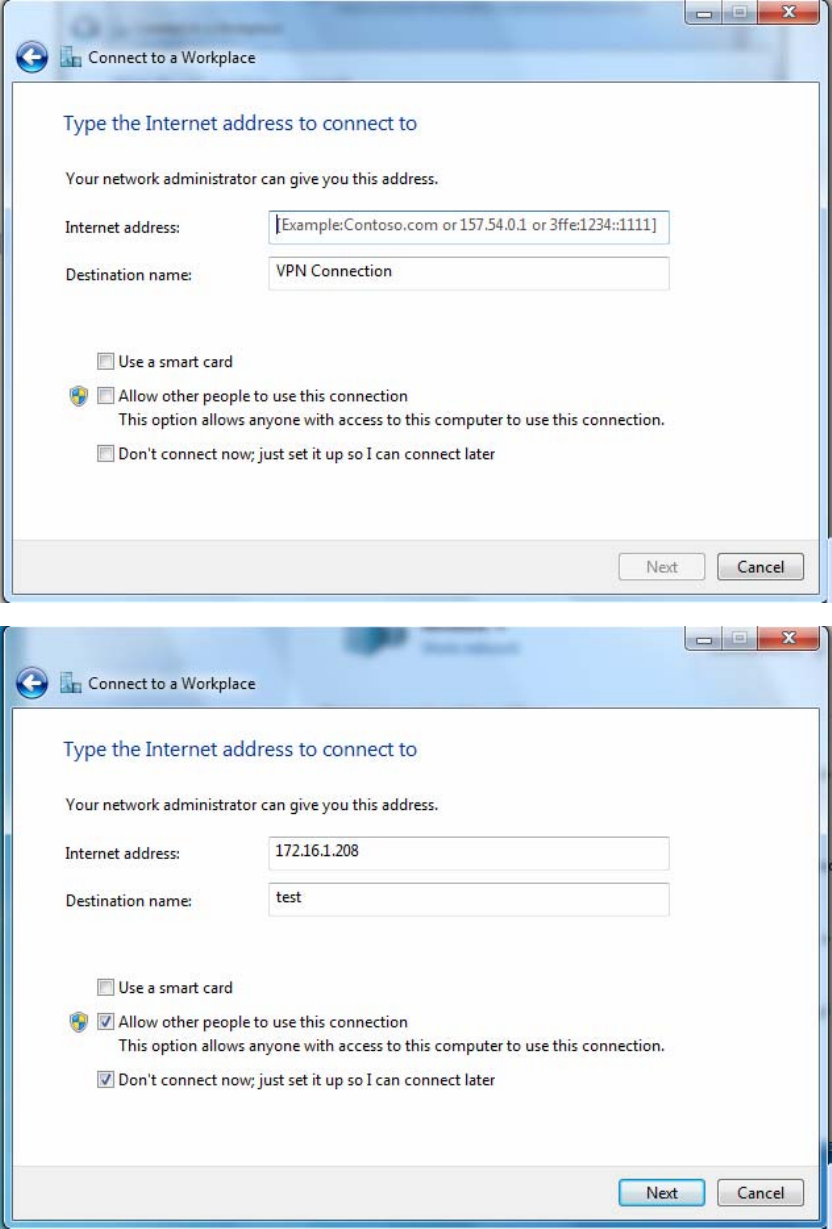
3. Select Use my Internet connection (VPN) and press Next.
195
4. Input Internet address and Destination name for this connection and press Next.
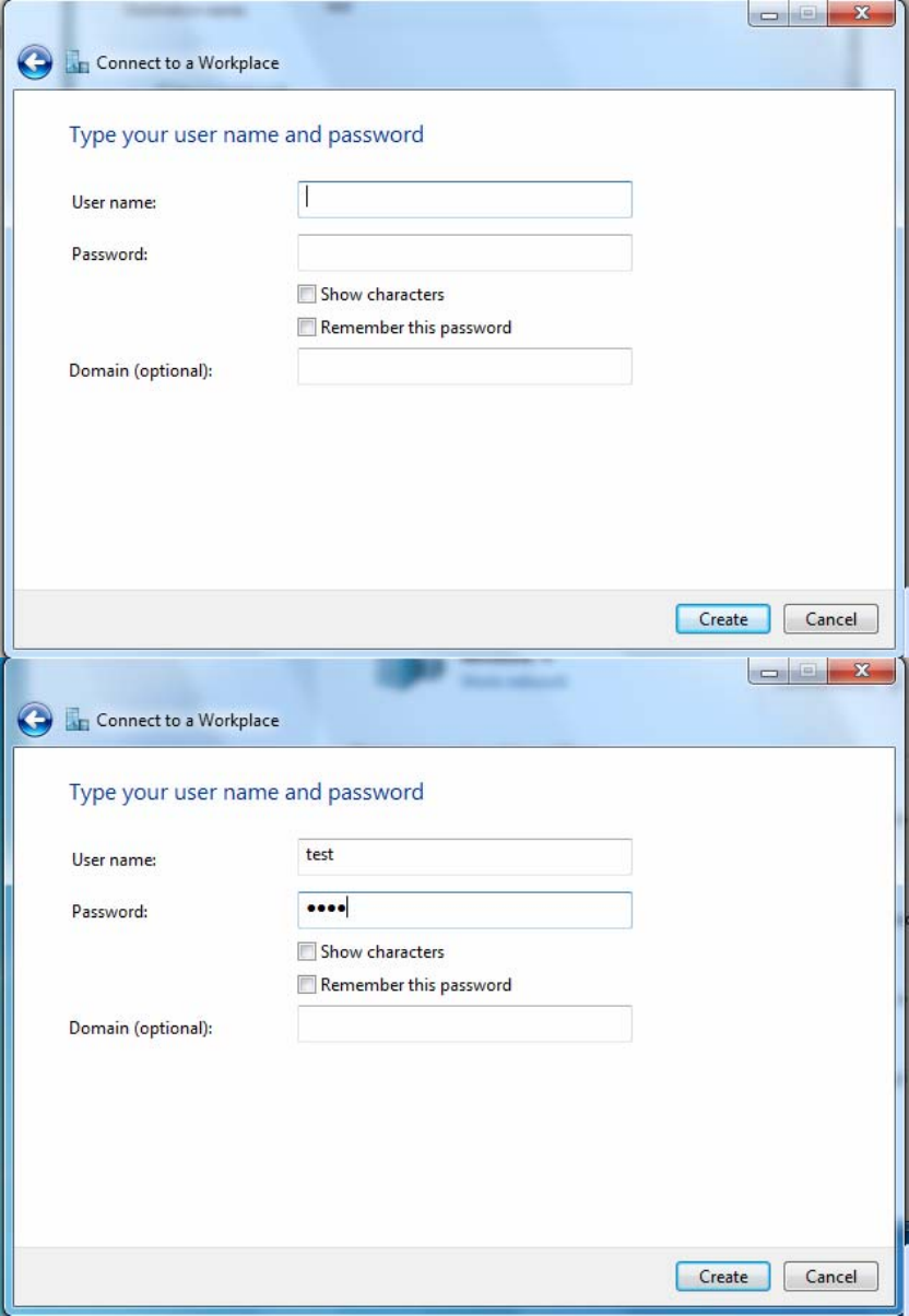
196
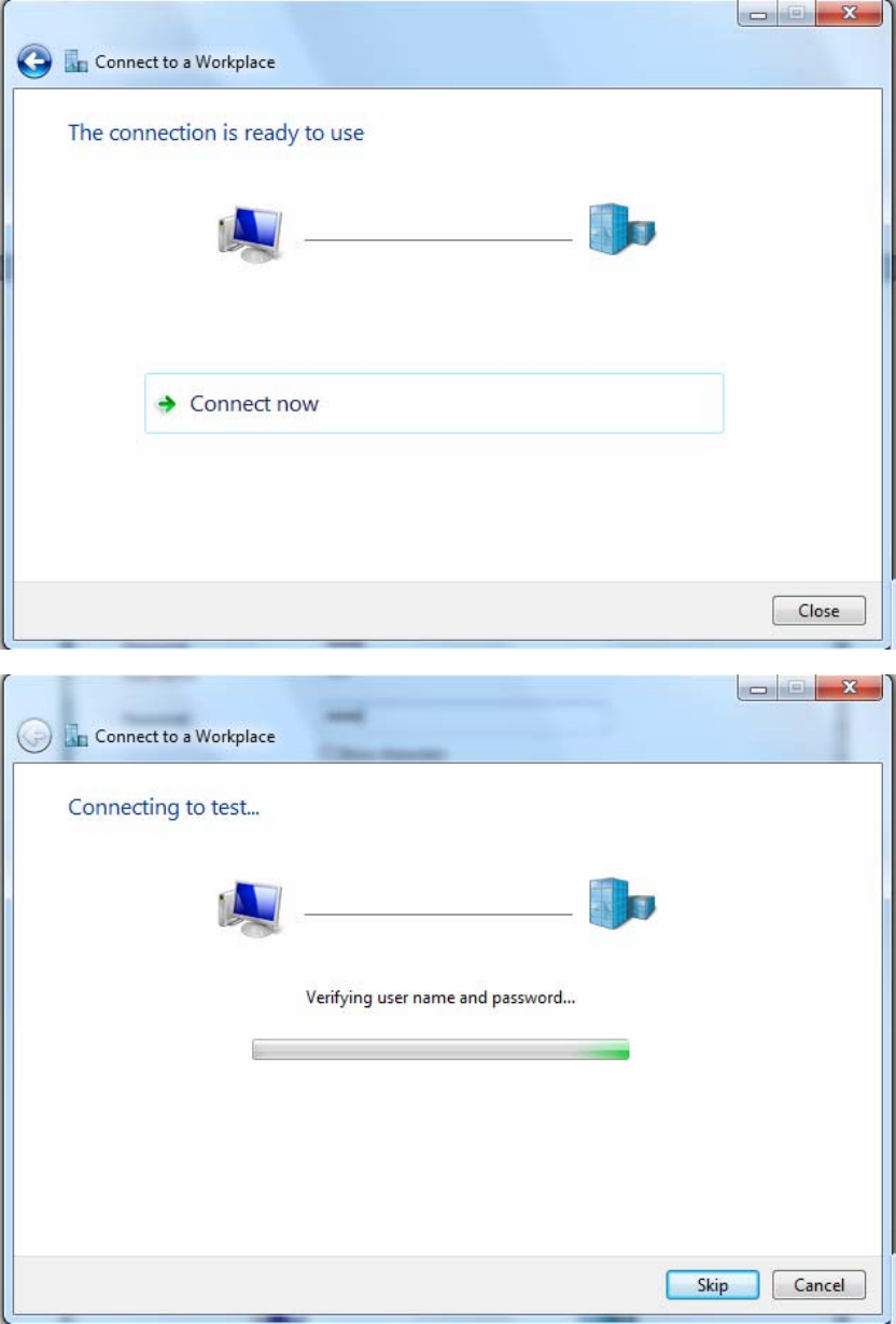
5. Input the account (user name and password) and press Create.
197
6. Connect to the server.
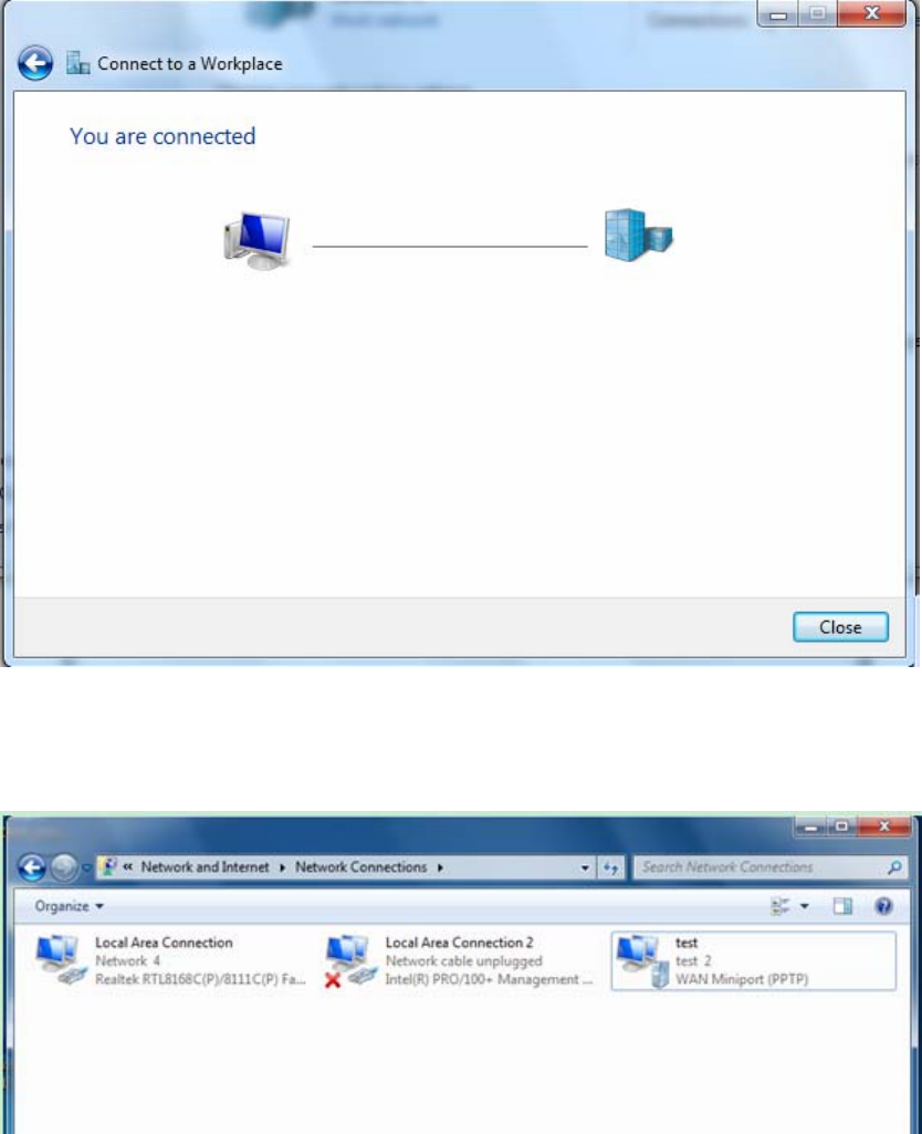
198
7. Successfully connected.
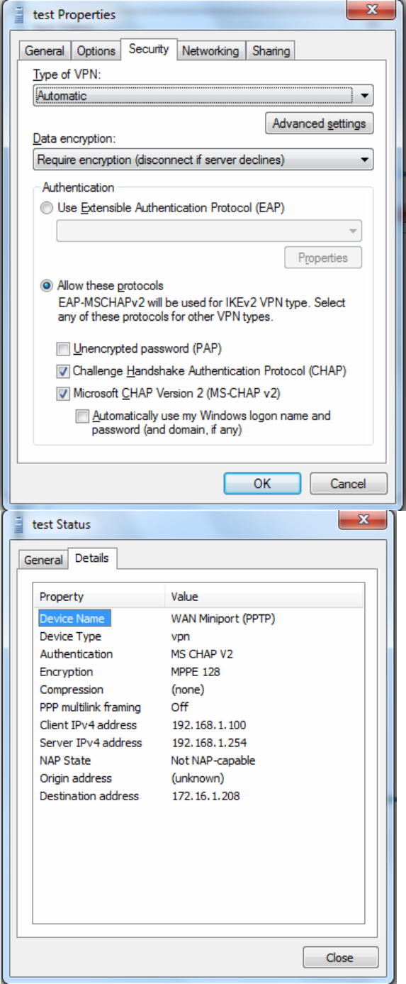
PS: You can also go to Network Connections shown below to check the detail of the connection.
Right click “test” icon, and select “Properties” to change the security parameters (if the connection
fails, users can go here to change the settings)
199
200
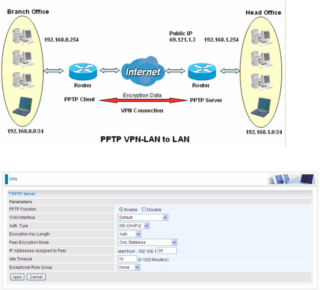
Example: Configuring a LAN-to-LAN PPTP VPN Connection
The branch office establishes a PPTP VPN tunnel with head office to connect two private networks
over the Internet. The routers are installed in the head office and branch offices accordingly.
Server side: Head Office
The above is the common setting for PPTP Server, set as you like for authentication and encryption.
The settings in Client side should be in accordance with settings in Server side.
201
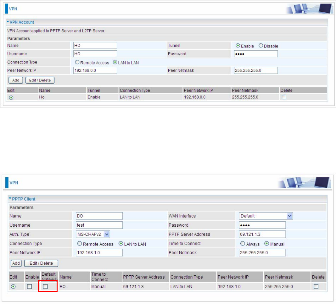
Then the PPTP Account.
Client Side: Branch Office
The client user can set up a tunnel connecting to the PPTP server, and can also set the tunnel as
the default route for all outgoing traffic.
Note: users can see the “Default Gateway” item in the bar, and user can check to select the tunnel
as the default gateway (default route) for traffic. If selected, all outgoing traffic will be forwarded to
this tunnel and routed to the next hop.
202
L2TP
The Layer 2 Tunneling Protocol (L2TP) is a Layer2 tunneling protocol for implementing virtual
private networks.
L2TP does not provide confidentiality or strong authentication by itself. 2222IPsec is often used to secure
L2TP packets by providing confidentiality, authentication and integrity. The combination of these two
protocols is generally known as L2TP/IPsec.
In L2TP section, both pure L2TP and L2TP/IPSec are supported. Users can choose your preferable
option for your own needs.
Note: 4 sessions for Client and only one for Server respectively.
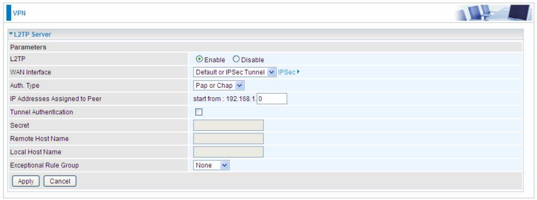
L2TP Server
In L2TP session, users can set the bassic parameters(authentication, encyption, peer address, etc)
for L2TP Server, and accounts in the page of VPN Account. They both constitutes the complete
L2TP Server settings.
L2TP: Select Enable to activate L2TP Server. Disable to deactivate L2TP Server.
WAN Interface: Select the exact WAN interface configured as source for the tunnel. Select different
interfaces, you will decide whether to use L2TP over IPSec or the pure L2TP.
L L2TP over IPSec, Select “Default or IPSec Tunnel” only when there is IPSec for L2TP rule in
place.
L Pure L2TP, Select Default (there is no IPSec for L2TP in place) or other interface to activate
the pure L2TP.
Auth. Type: The authentication type, Pap or Chap, PaP, Chap. When using PAP, the password is
sent unencrypted, whilst CHAP encrypts the password before sending, and also allows for
challenges at different periods to ensure that an intruder has not replaced the client.
IP Addresses Assigned to Peer: 192.168.1.x: please input the IP assigned range from 1~ 254.
Tunnel Authentication: Select whether to enable L2TP tunnel authentication. Enable it if needed

203
and set the same in the client side.
Secret: Enter the secretly pre-shared password for tunnel authentication.
Remote Host Name: Enter the remote host name (of peer) featuring the destination of the L2TP
tunnel.
Local Host Name: Enter the local host name featuring the source of the L2TP tunnel.
Exceptional Rule Group: Select to grant or block access to a group of IPs to the L2TP server. See
2222Exceptional Rule Group. If there is not any restriction, select none.
Click Apply to submit your L2TP Server basic settings.
204
L2TP Client
L2TP client can help you dial-in the L2TP server to establish L2TP tunnel over Internet.
Name: user-defined name for identification.
L2TP over IPSec: If your L2TP server has used L2TP over IPSec feature, please enable this item.
under this circumstance, client and server communicate using L2TP over IPSec.
L Enable
IPSec Tunnel: Select the appropriate IPSec for L2TP rule configured for the L2TP Client.
Username: Enter the username provided by your L2TP Server.
Password: Enter the password provided by your L2TP Server.
Auth. Type: Default is Pap or CHap if you want the router to determine the authentication type to
use, or else manually specify CHAP (Challenge Handshake Authentication Protocol) or PAP
(Password Authentication Protocol) if you know which type the server is using. When using PAP, the
password is sent unencrypted, whilst CHAP encrypts the password before sending, and also allows
for challenges at different periods to ensure that an intruder has not replaced the client.
L2TP Server Address: Enter the IP address of the L2TP server.
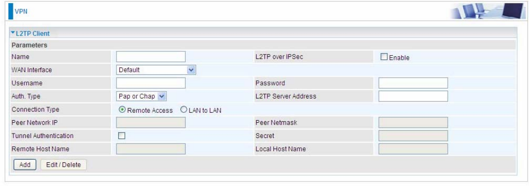
205
Connection Type: Select Remote Access for single user, Select LAN to LAN for remote gateway.
Peer Network IP: Please input the subnet IP for Server.
Peer Netmask: Please input the Netmask for Server.
Tunnel Authentication: Select whether to enable L2TP tunnel authentication, if the server side
enables this feature, please follow.
Secret: Enter the set secret password in the server side.
Remote Host Name: Enter the remote host name featuring the destination of the L2TP tunnel.
Local Host Name: Enter the local host name featuring the source of the L2TP tunnel.
Click Add button to save your changes.
L Disable
WAN Interface: Select the exact WAN interface configured for the tunnel. Select Default to use the
now-working WAN interface for the tunnel. Under this circumstance, client and server communicate
through pure L2TP server.
Username: Enter the username provided by your L2TP Server.
Password: Enter the password provided by your L2TP Server.
Auth. Type: Default is Pap or CHap if you want the router to determine the authentication type to
use, or else manually specify CHAP (Challenge Handshake Authentication Protocol) or PAP
(Password Authentication Protocol) if you know which type the server is using. When using PAP, the
password is sent unencrypted, whilst CHAP encrypts the password before sending, and also allows
for challenges at different periods to ensure that an intruder has not replaced the client.
L2TP Server Address: Enter the IP address of the L2TP server.
Connection Type: Select Remote Access for single user, Select LAN to LAN for remote gateway.
Peer Network IP: Please input the subnet IP for Server.
Peer Netmask: Please input the Netmask for server.
Tunnel Authentication: Select whether to enable L2TP tunnel authentication, if the server side
enables this feature, please follow.
206
Secret: Enter the set secret password in the server side.
Remote Host Name: Enter the remote host name featuring the destination of the L2TP tunnel.
Local Host Name: Enter the local host name featuring the source of the L2TP tunnel.
Click Add button to save your changes.
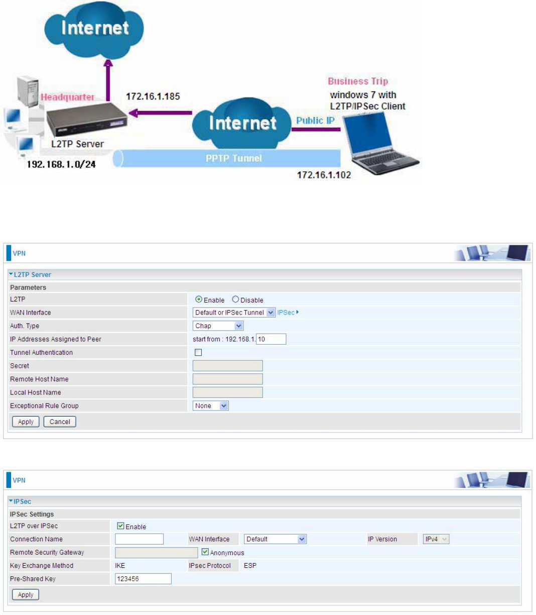
207
Example: L2TP over IPSec Remote Access with Windows7
(Note: inside test with 172.16.1.185, just an example for illustration)
Server Side:
1. Configuration > VPN > L2TP and Enable the L2TP function, Click Apply.
The IPSec for L2TP rule
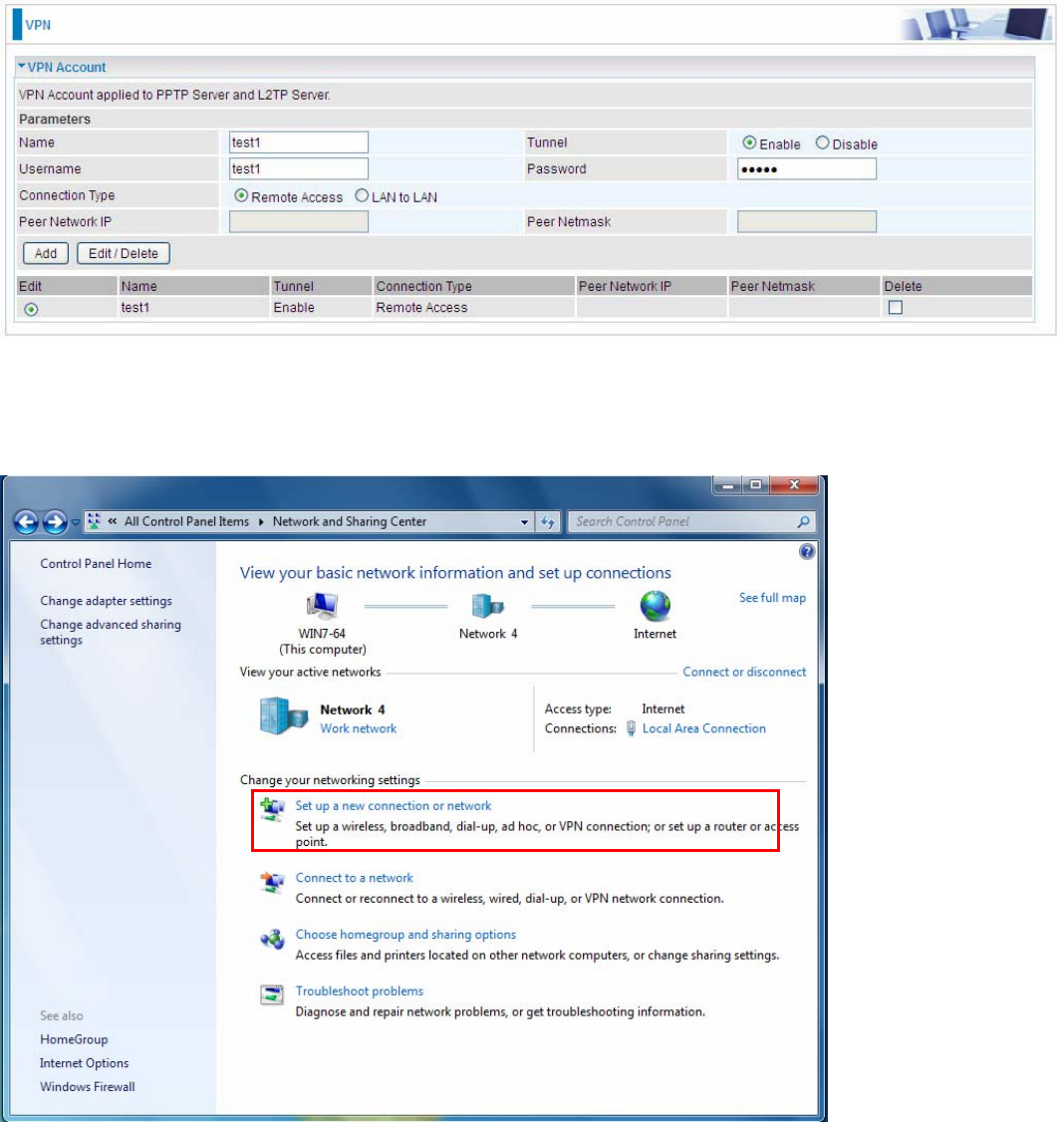
208
2. Create a L2TP Account “test1”.
Client Side:
1. In Windows7 click Start > Control Panel> Network and Sharing Center, Click Set up a new
connection network.
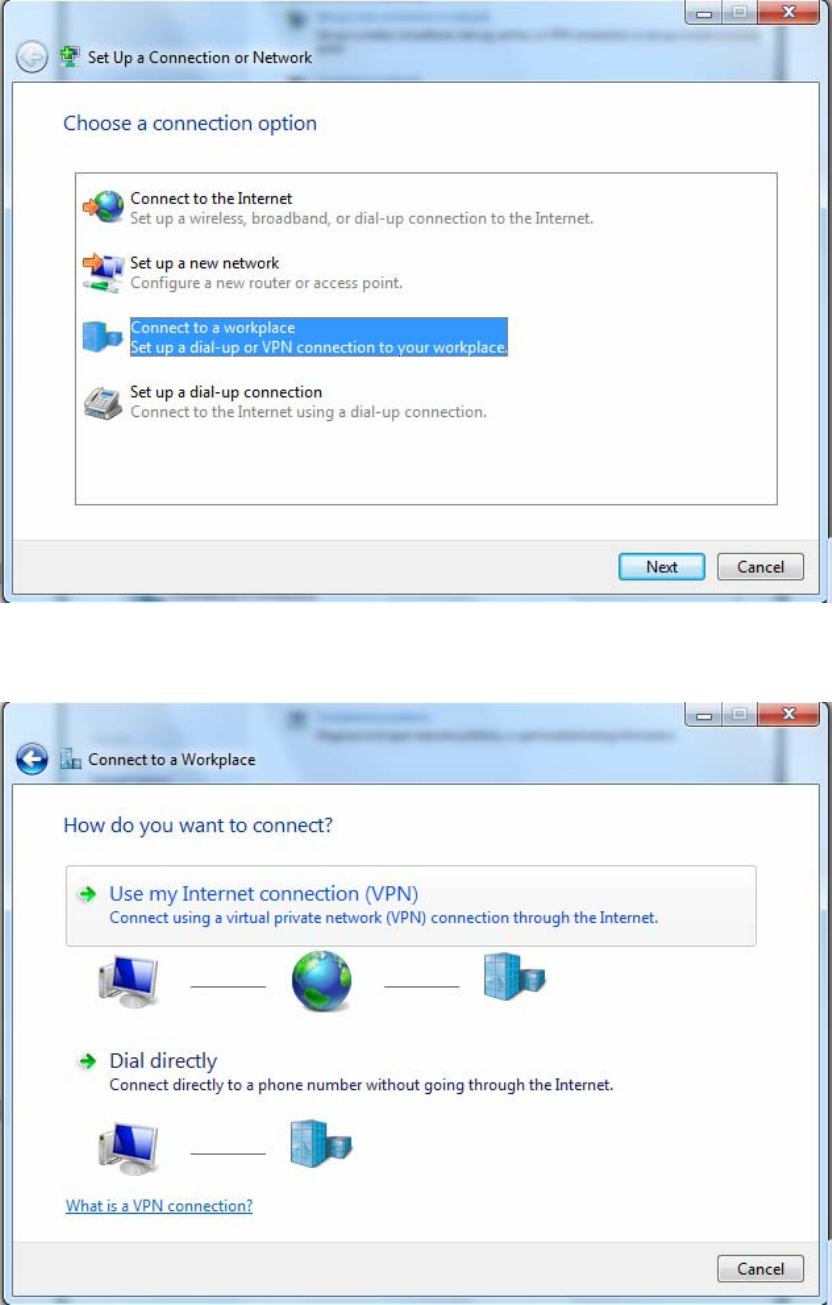
209
2. Click Connect to a workplace, and press Next.
3. Select Use my Internet connection (VPN) and press Next.
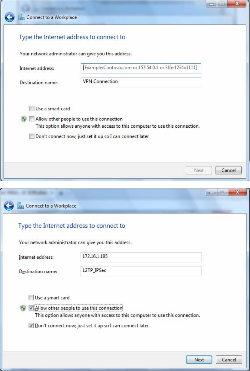
210
4. Input Internet address and Destination name for this connection and press Next.
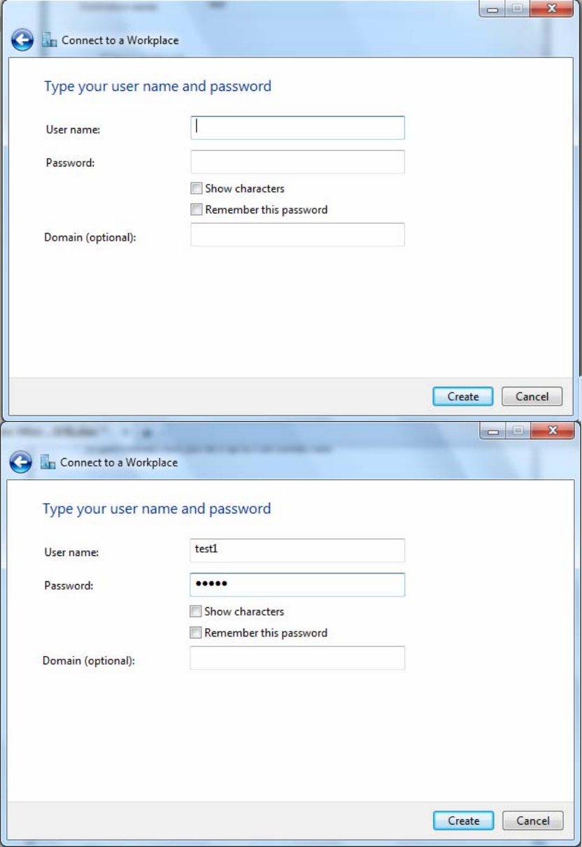
211
5. Input the account (user name and password) and press Create.
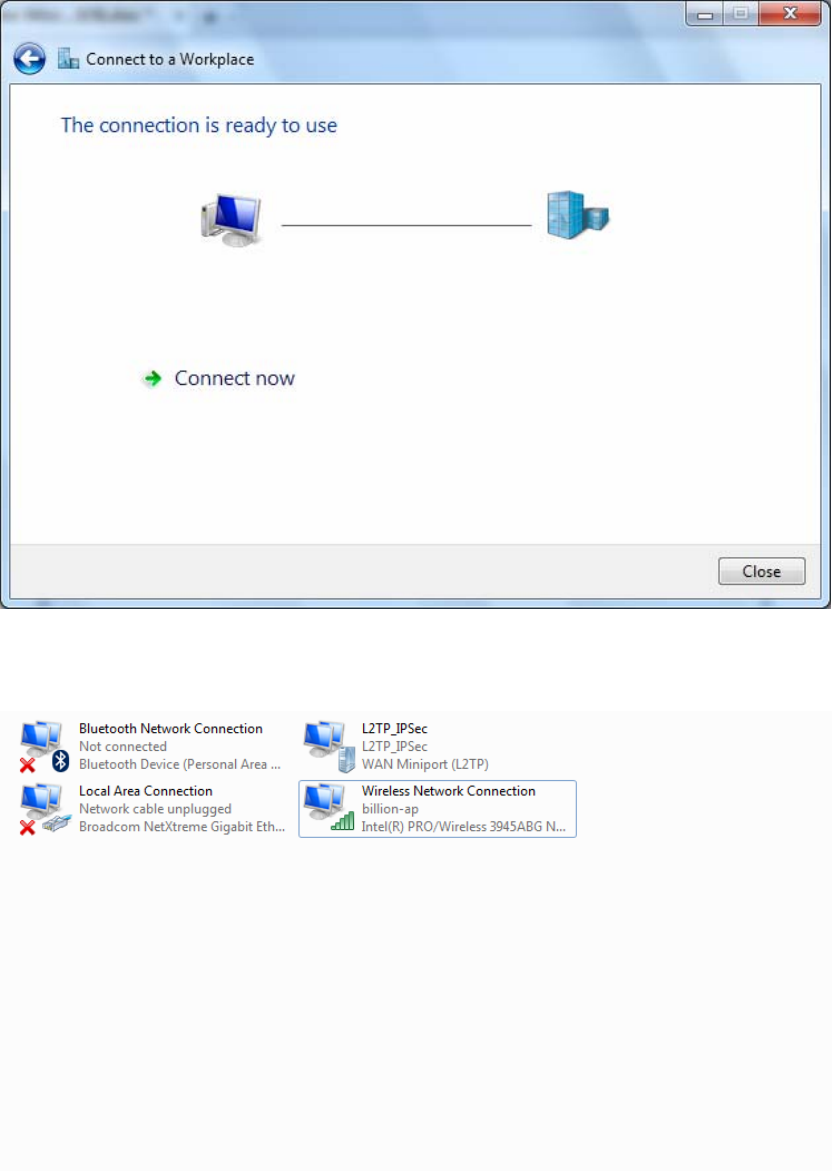
212
6. Connection created. Press Close.
7. Go to Network Connections shown below to check the detail of the connection. Right click
“L2TP_IPSec” icon, and select “Properties” to change the security parameters.
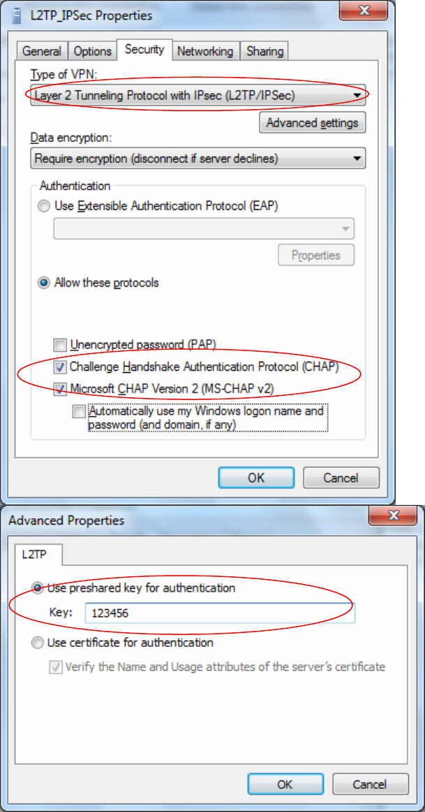
213
8. Chang the type of VPN to “Layer 2 Tunneling Protocol with IPSec (L2TP/IPSec)” and Click
Advanced Settings to set the pre-shared (set in IPSec) key for authentication.
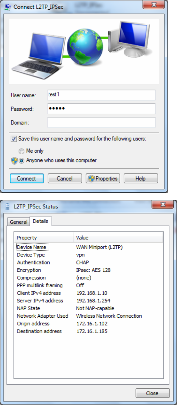
214
9. Go to Network connections, enter username and password to connect L2TP_IPSec and check
the connection status.
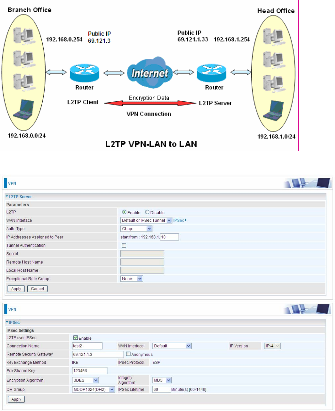
215
Example: Configuring L2TP LAN-to-LAN VPN Connection
The branch office establishes a L2TP VPN tunnel with head office to connect two private networks
over the Internet. The routers are installed in the head office and branch office accordingly.
Note: Both office LAN networks must be in different subnets with the LAN-LAN application.
Server side: Head Office
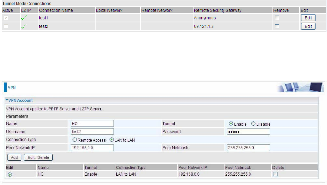
216
The above is the commonly setting for L2TP Server, set as you like for authentication and encryption.
The settings in Client side should be in accordance with settings in Server side.
Then account the L2TP Account.
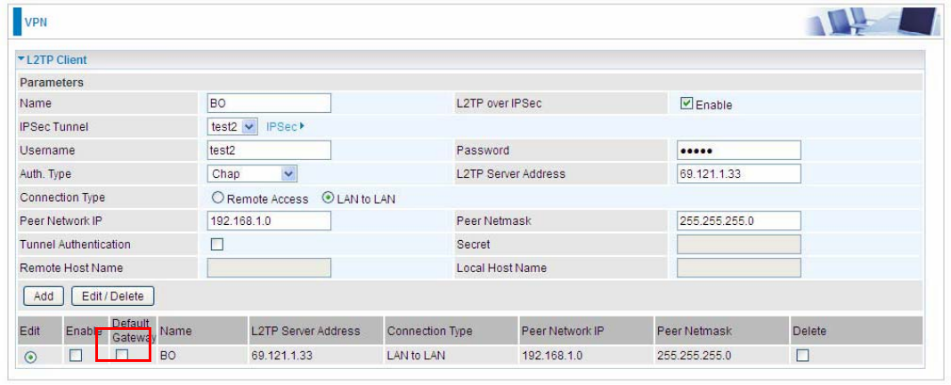
217
Client Side: Branch Office
The client user can set up a tunnel connecting to the L2TP server, and can also set the tunnel as the
default route for all outgoing traffic.
Note: users can see the “Default Gateway” item in the bar, and user can check to select the tunnel
as the default gateway (default route) for traffic. If selected, all outgoing traffic will be forwarded to
this tunnel and routed to the next hop.
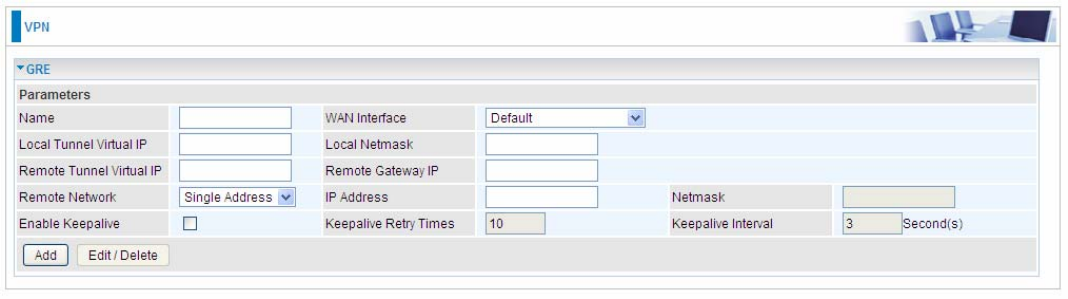
218
GRE
Generic Routing Encapsulation (GRE) is a tunneling protocol that can encapsulate a wide variety
of network layer protocol packets inside virtual point-to-point links over an Internet Protocol (IP)
network.
Note: up to 8 tunnels can be added, but only 4 can be activated.
Name: User-defined identification.
WAN Interface: Select the exact WAN interface configured for the tunnel as the source tunnel IP.
Select Default to use the now-working WAN interface for the tunnel.
Local Tunnel Virtual IP: Please input the virtual IP for the local tunnel.
Local Netmask: Input the netmask for the local tunnel.
Remote Tunnel Virtual IP: Please input the virtual destination IP for tunnel.
Remote Gateway IP: Set the destination IP for the tunnel.
Remote Network: Select the peer topology, Single address (client) or Subnet.
IP Address: Set the IP address if the peer is a client. If the peer is a subnet, please enter the IP and
netmask.
Enable Keepalive: Normally, the tunnel interface is always up. Enable keepalive to determine when
the tunnel interface is to be closed. The local router sends keepalive packets to the peer router, if
keepalive response is not received from peer router within the allowed time (‘retry time’ multiply
‘interval’, based on default settings, the time interval can be 30 seconds), the local router will shut up
its tunnel interface.
Keepalive Retry Times: Set the keepalive retry times, default is 10.
Keepalive Interval: Set the keepalive Interval, unit in seconds. Default is 3 seconds.
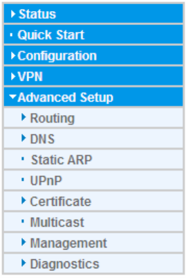
219
Advanced Setup
There are sub-items within the System section: Routing, DNS, Static ARP, UPnP, Certificate,
Multicast, Management, and Diagnostics.
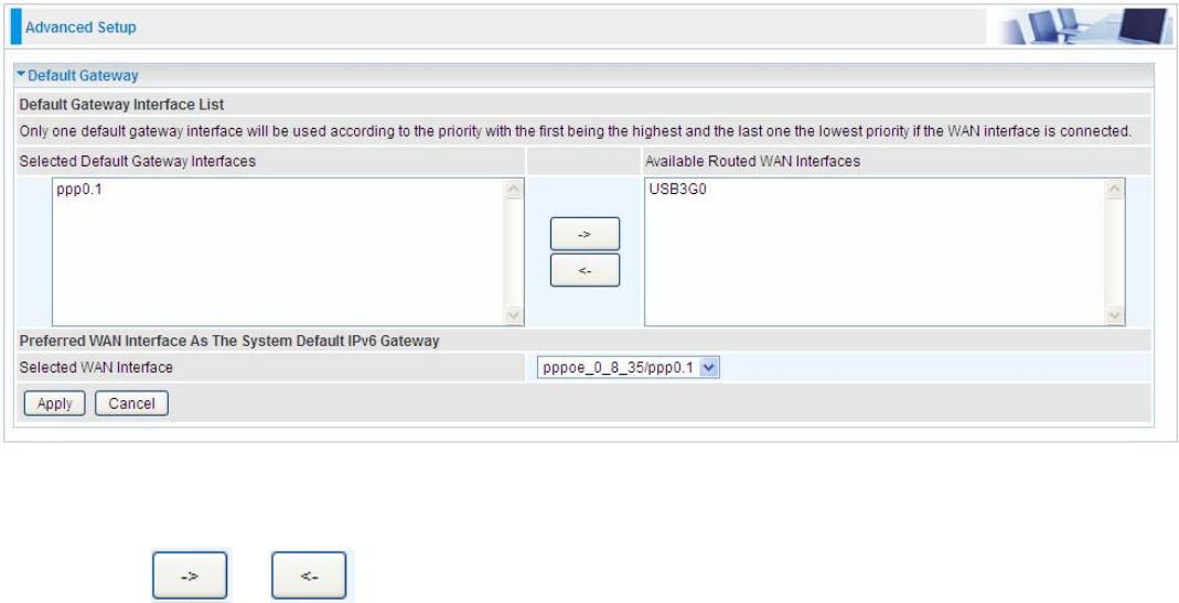
220
Routing
Default Gateway
To set Default Gateway and Available Routed WAN Interface. This interfaces are the ones you
have set in WAN section, here select the one you want to be the default gateway by moving the
interface via or . And select a Default IPv6 Gateway from the drop-down menu.
Note: Only one default gateway interface will be used according to the priority with the first being the
highest and the last one the lowest priority if the WAN interface is connected.
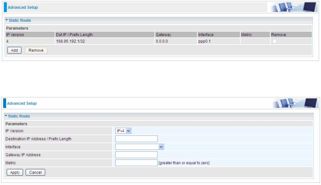
221
Static Route
With static route feature, you can control the routing of all the traffic across your network. With each
routing rule created, you can specifically assign the destination where the traffic will be routed.
Above is the static route listing table, click Add to create static routing.
IP Version: Select the IP version, IPv4 or IPv6.
Destination IP Address / Prefix Length: Enter the destination IP address and the prefix length. For
IPv4, the prefix length means the number of ‘1’ in the submask, it is another mode of presenting
submask. One IPv4 address,192.168.1.0/24, submask is 255.255.255.0. While in IPv6, IPv6
address composes of two parts, thus, the prefix and the interface ID, the prefix is like the net ID in
IPv4, and the interface ID is like the host ID in IPv4. The prefix length is to identify the net ID in the
address. One IPv6 address, 3FFE:FFFF:0:CD30:0:0:0:0 / 64, the prefix is 3FFE:FFFF:0:CD3.
Interface: Select an interface this route associated.
Gateway IP Address: Enter the gateway IP address.
Metric: Metric is a policy for router to commit router, to determine the optimal route. Enter one
number greater than or equal to 0.
Click Apply to apply this route and it will be listed in the route listing table.
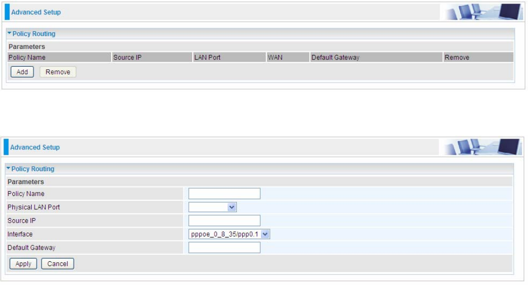
222
Policy Routing
Here users can set a route for the host (source IP) in a LAN interface to access outside through a
specified Default Gateway or a WAN interface.
The following is the policy Routing listing table.
Click Add to create a policy route.
Policy Name: User-defined name.
Physical LAN Port: Select the LAN port.
Source IP: Enter the Host Source IP.
Interface: Select the WAN interface which you want the Source IP to access outside through.
Default Gateway: Enter the default gateway which you want the Source IP to access outside
through.
Click Apply to apply your settings. And the item will be listed in the policy Routing listing table. Here
if you want to remove the route, check the remove checkbox and press Remove to delete it.
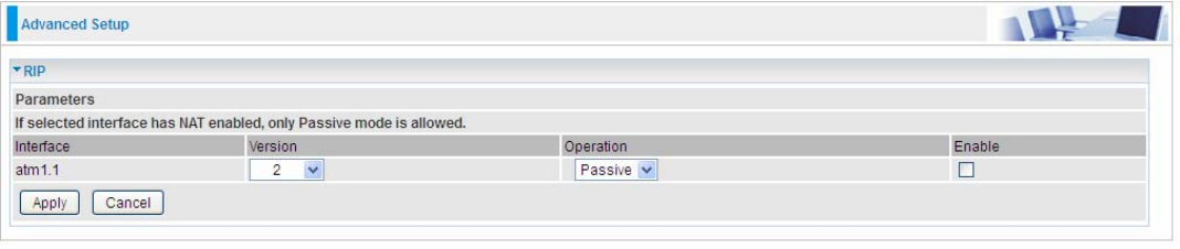
223
RIP
RIP, Router Information Protocol, is a simple Interior Gateway Protocol (IGP). RIP has two versions,
RIP-1 and RIP-2.
Interface: the interface the rule applies to.
Version: select the RIP version, RIP-1, RIP-2 and both.
Operation: RIP has two operation mode.
L Passive: only receive the routing information broadcasted by other routers and modifies its
routing table according to the received information.
L Active: working in this mode, the router sends and receives RIP routing information and
modifies routing table according to the received information.
Enable: check the checkbox to enable RIP rule for the interface.
Note: RIP can’t be configured on the WAN interface which has NAT enabled (such as PPPoE).
Click Apply to apply your settings.