Billion Electric BIL-AWDL060 4G LTE Embedded Mini-Card Module User Manual

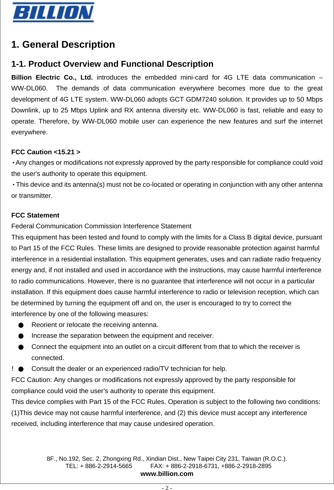
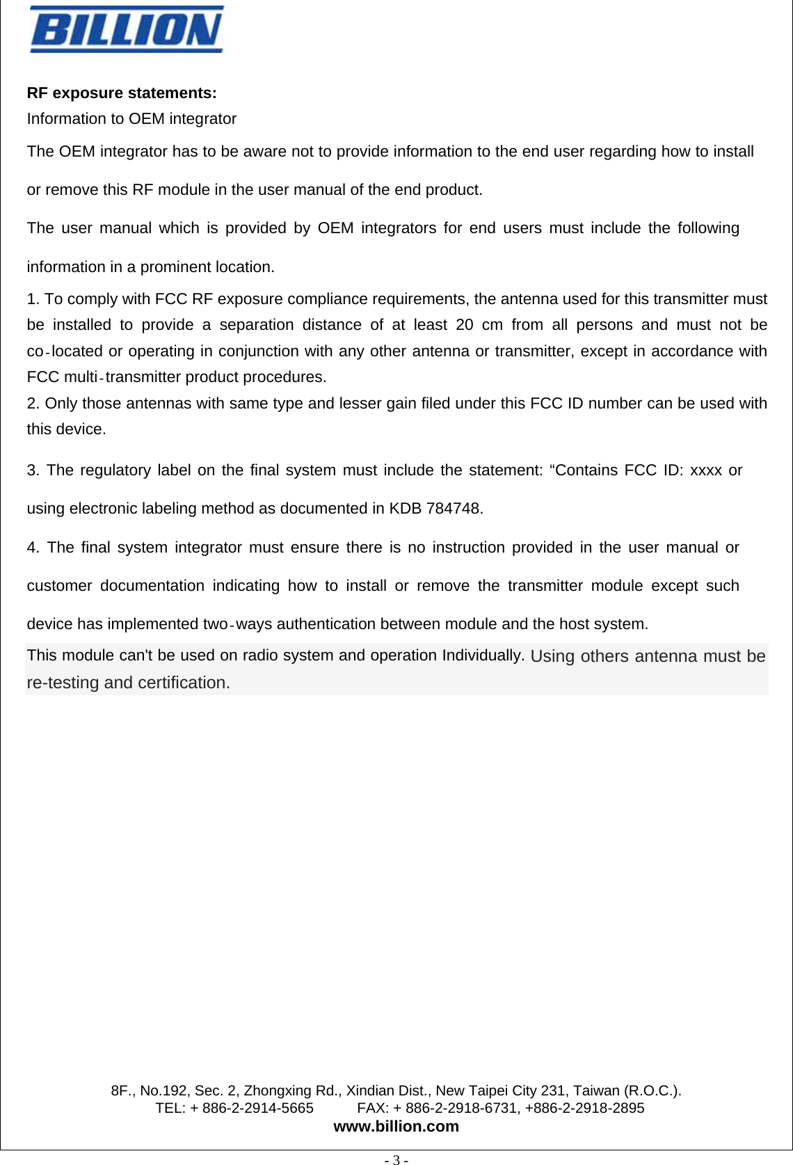
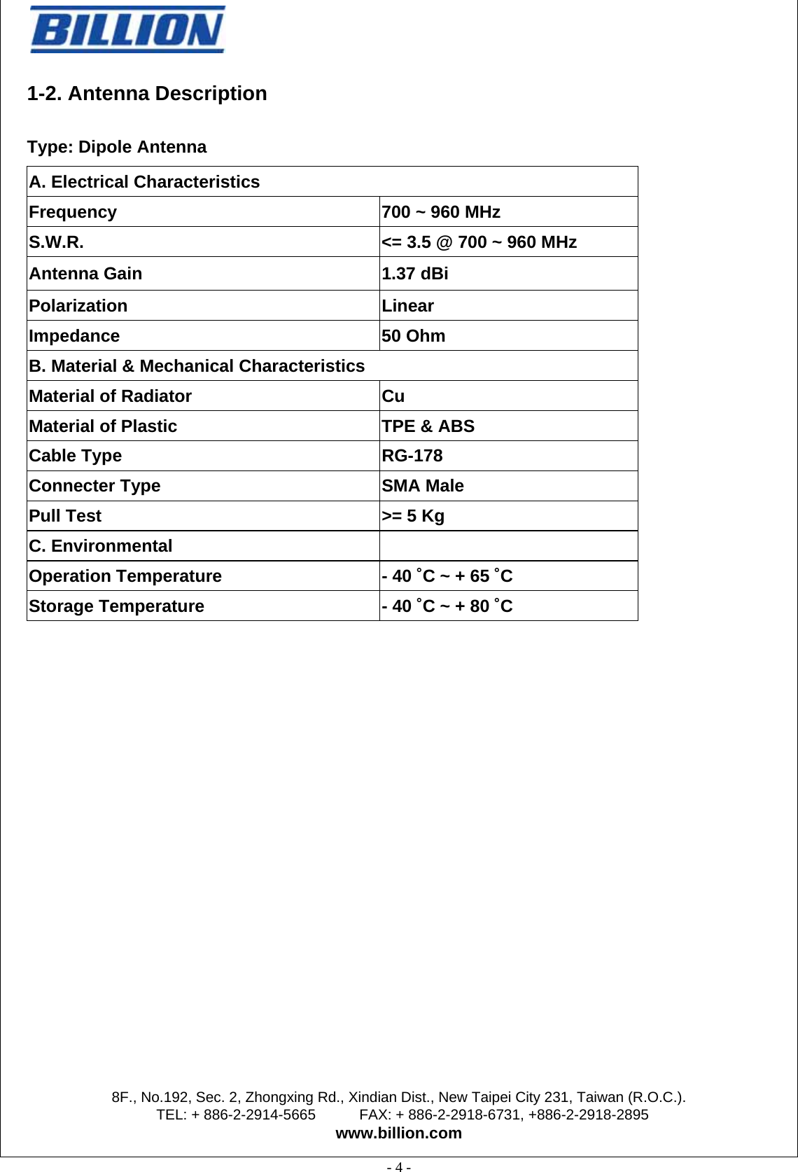
Billion Electric Co., Ltd. 4G LTE Embedded Mini-Card Module

User Manual

                                                 8F., No.192, Sec. 2, Zhongxing Rd., Xindian Dist., New Taipei City 231, Taiwan (R.O.C.). TEL: + 886-2-2914-5665      FAX: + 886-2-2918-6731, +886-2-2918-2895 www.billion.com  - 1 -     WW-DL060   4G LTE Embedded Mini-Card Module Standard     Version 0.4  Document release  Date Modification  Initials Approved Version 0.1  2013/06/10 Initial version  James Li  Daniel Lee Verison 0.2  2013/07/09 Spec update    Daniel  Daniel Verison 0.3  2013/07/09 Add packing SOP  Irene Lin  Irene Lin Version 0.4  2013/07/29 Update packing SOP  Fiona Liang  Fiona Liang
                                                 8F., No.192, Sec. 2, Zhongxing Rd., Xindian Dist., New Taipei City 231, Taiwan (R.O.C.). TEL: + 886-2-2914-5665      FAX: + 886-2-2918-6731, +886-2-2918-2895 www.billion.com  - 2 -   1. General Description 1-1. Product Overview and Functional Description Billion Electric Co., Ltd. introduces the embedded mini-card for 4G LTE data communication – WW-DL060.  The demands of data communication everywhere becomes more due to the great development of 4G LTE system. WW-DL060 adopts GCT GDM7240 solution. It provides up to 50 Mbps Downlink, up to 25 Mbps Uplink and RX antenna diversity etc. WW-DL060 is fast, reliable and easy to operate. Therefore, by WW-DL060 mobile user can experience the new features and surf the internet everywhere. FCC Caution <15.21 >   ‧Any changes or modifications not expressly approved by the party responsible for compliance could void the user's authority to operate this equipment.   ‧This device and its antenna(s) must not be co-located or operating in conjunction with any other antenna or transmitter.   FCC Statement Federal Communication Commission Interference Statement This equipment has been tested and found to comply with the limits for a Class B digital device, pursuant to Part 15 of the FCC Rules. These limits are designed to provide reasonable protection against harmful interference in a residential installation. This equipment generates, uses and can radiate radio frequency energy and, if not installed and used in accordance with the instructions, may cause harmful interference to radio communications. However, there is no guarantee that interference will not occur in a particular installation. If this equipment does cause harmful interference to radio or television reception, which can be determined by turning the equipment off and on, the user is encouraged to try to correct the interference by one of the following measures:   ●    Reorient or relocate the receiving antenna.   ●    Increase the separation between the equipment and receiver.   ●    Connect the equipment into an outlet on a circuit different from that to which the receiver is connected. ! ●    Consult the dealer or an experienced radio/TV technician for help. FCC Caution: Any changes or modifications not expressly approved by the party responsible for compliance could void the user’s authority to operate this equipment. This device complies with Part 15 of the FCC Rules. Operation is subject to the following two conditions: (1)This device may not cause harmful interference, and (2) this device must accept any interference received, including interference that may cause undesired operation.
                                                 8F., No.192, Sec. 2, Zhongxing Rd., Xindian Dist., New Taipei City 231, Taiwan (R.O.C.). TEL: + 886-2-2914-5665      FAX: + 886-2-2918-6731, +886-2-2918-2895 www.billion.com  - 3 -   RF exposure statements:   Information to OEM integrator The OEM integrator has to be aware not to provide information to the end user regarding how to install or remove this RF module in the user manual of the end product. The user manual which is provided by OEM integrators for end users must include the following information in a prominent location. 1. To comply with FCC RF exposure compliance requirements, the antenna used for this transmitter must be installed to provide a separation distance of at least 20 cm from all persons and must not be co located or operating in conjunction with any other antenna or transmitter, except in accordance with FCC multi transmitter product procedures. 2. Only those antennas with same type and lesser gain filed under this FCC ID number can be used with this device.  3. The regulatory label on the final system must include the statement: “Contains FCC ID: xxxx or using electronic labeling method as documented in KDB 784748. 4. The final system integrator must ensure there is no instruction provided in the user manual or customer documentation indicating how to install or remove the transmitter module except such device has implemented two ways authentication between module and the host system. This module can't be used on radio system and operation Individually. Using others antenna must be re-testing and certification.
                                                 8F., No.192, Sec. 2, Zhongxing Rd., Xindian Dist., New Taipei City 231, Taiwan (R.O.C.). TEL: + 886-2-2914-5665      FAX: + 886-2-2918-6731, +886-2-2918-2895 www.billion.com  - 4 -   1-2. Antenna Description Type: Dipole Antenna A. Electrical Characteristics  Frequency  700 ~ 960 MHz S.W.R.  <= 3.5 @ 700 ~ 960 MHz Antenna Gain  1.37 dBi   Polarization Linear Impedance 50 Ohm B. Material & Mechanical Characteristics  Material of Radiator  Cu Material of Plastic  TPE & ABS Cable Type  RG-178 Connecter Type  SMA Male Pull Test  >= 5 Kg C. Environmental    Operation Temperature  - 40 ˚C ~ + 65 ˚C  Storage Temperature  - 40 ˚C ~ + 80 ˚C
                                                 8F., No.192, Sec. 2, Zhongxing Rd., Xindian Dist., New Taipei City 231, Taiwan (R.O.C.). TEL: + 886-2-2914-5665      FAX: + 886-2-2918-6731, +886-2-2918-2895 www.billion.com  - 5 -   1-2. Key Features   Supporting Following Standards LTE : Long Term Evaluation (3GPP E-UTRA Release 8) E-UTRA: Evolved Universal Terrestrial Radio Access    Supporting Following Service LTE packet data service    Supporting Following Features FDD: Frequency Division Duplex RX diversity Uplink data rate up to 25 Mbps Downlink data rate up to 50 Mbps Mini PCI Express form factor, USB interface   *Maximum data rate is subject to 4G services provided by network operators Operating Systems Supported Microsoft Windows XP ,Microsoft Vista , Microsoft Windows 7 Android: 2.3, 3.0, 4.0 Linux:
                                                 8F., No.192, Sec. 2, Zhongxing Rd., Xindian Dist., New Taipei City 231, Taiwan (R.O.C.). TEL: + 886-2-2914-5665      FAX: + 886-2-2918-6731, +886-2-2918-2895 www.billion.com  - 6 -   1-3. Specifications Table Model Name  WW-DL060  Product Description  4G LTE embedded mini card module Technical Standard  z LTE (3GPP R8)  Host Interface  USB (through mini-PCI Express interface) Operating Conditions Voltage  3.3V Temperature  Operating: -20~70 Storage: -40~85Humidity  15% ~ 95% Dimension  51mm X 30mm Form Factor  Mini PCI Express Card Electrical Specifications Operating Frequency FDD 700 MHz (Band 12): z UP-Link:699~716 MHz z DL-Link: 729~746 MHz Maximum Output Power  z LTE 700 MHz: 23dBm (Class 3) Antenna   Dual IPEX antenna port Receive Sensitivity  z LTE 700 MHz: compliant with 3GPP TS 36.521-1
                                                 8F., No.192, Sec. 2, Zhongxing Rd., Xindian Dist., New Taipei City 231, Taiwan (R.O.C.). TEL: + 886-2-2914-5665      FAX: + 886-2-2918-6731, +886-2-2918-2895 www.billion.com  - 7 -   2. Electrical Characteristics 2-1. Recommended Operating Conditions Power  Parameter  Tolerance  Units 3.3V  Module power supply  +-9%  V  2-2. Power supply and Current Requirement: The WW-DL060 complies with PCI express Mini CEM specifications v1.2.   PCI express Mini CEM specifications define as the below Table: Power  Tolerance  Max. Current  Idle Current 3.3V  +-9%  700 mA  TBD mA Note. The idle current is generally less than 100mA, depending on the FW version.
                                                 8F., No.192, Sec. 2, Zhongxing Rd., Xindian Dist., New Taipei City 231, Taiwan (R.O.C.). TEL: + 886-2-2914-5665      FAX: + 886-2-2918-6731, +886-2-2918-2895 www.billion.com  - 8 -   3. Pin Definition 3-1.   Pin Assignment  Pin No  Definition  Basic Description  Type   1  NC  No connect     2  3.3V  3.3V DC supply  Input   3  NC  No connect     4  GND  Ground     5  NC  No connect     6  NC  No connect     7  NC  No connect     8  UIM_PWR  Power source for external UIM/SIM  Output   9  GND  Ground     10  UIM_DATA  External UIM/SIM data signal  Input/output  11  NC  No connect     12  UIM_CLK  External UIM/SIM clock signal  Output   13  NC  No connect    14  UIM_RESET  External UIM/SIM reset signal  Output   15  GND  Ground     16  NC  No connect     17  NC  No connect     18  GND  Ground     19  NC  No connect     20  NC  No connect     21  GND  Ground     22  *NC  No connect   Note 1 23  NC  No connect     24  3.3Vaux  3.3V_FMC DC supply     25  NC  No connect     26  GND  Ground     27  GND  Ground     28  NC  No connect     29  GND  Ground     30  NC  No connect
                                                 8F., No.192, Sec. 2, Zhongxing Rd., Xindian Dist., New Taipei City 231, Taiwan (R.O.C.). TEL: + 886-2-2914-5665      FAX: + 886-2-2918-6731, +886-2-2918-2895 www.billion.com  - 9 -   Pin No  Definition  Basic Description  Type   31  NC  No connect     32  NC  No connect     33  NC  No connect     34  GND  Ground     35  GND  Ground     36  USB_D-  USB signal D-  Input/Output  37  GND  Ground     38  USB_D+  USB signal D+  Input/Output  39  3.3Vaux  3.3V_FMC DC supply  Input   40  GND  Ground     41  3.3Vaux  3.3V_FMC  DC supply  Input   42  LED_WWAN_1  Active Low LED signal for indicating the state of the module open drain structure If no use this pin, connect to GND  Output   43  GND  Ground     44  NC  No connect     45  NC  No connect     46  NC  No connect     47  NC  No connect     48  NC  No connect     49  NC  No connect     50  GND  Ground     51  NC  No connect     52  3.3V  3.3V DC power supply  Input   Note: Please don’t series NC pin to ground or bias voltage.  Note1: Please keep pin 22 NC If want to preset module Recommend to add a switch to turn off and turn on 3.3V DC power
                                                 8F., No.192, Sec. 2, Zhongxing Rd., Xindian Dist., New Taipei City 231, Taiwan (R.O.C.). TEL: + 886-2-2914-5665      FAX: + 886-2-2918-6731, +886-2-2918-2895 www.billion.com  - 10 -   4. Mechanical drawing

Navigation menu