Bird Technologies Group 5PI616850 SIGAL BOOSTER 2 User Manual 9386S1 1
Bird Technologies Group SIGAL BOOSTER 2 9386S1 1
Contents
- 1. USERS MANUAL 1
- 2. USERS MANUAL 2
- 3. USERS MANUAL 3
- 4. USERS MANUAL 4
USERS MANUAL 2
Manual 7-9386-1 Page 9TX RX Systems Inc. 09/30/04
61-68-50 UserMan page 9 of 25
the unit and the possibility for injury if the unit
should become detached from its mounting sur-
faces for any reason.
Although signal boosters can operate for years
without being attended to, the unit will need to be
accessed by service personnel with troubleshoot-
ing equipment, such as digital multimeters and
spectrum analyzer or a laptop computer from time
to time. The location of the power source will also
have a bearing on the mounting location. SB II
uses external heat sinks and needs to be mounted
where there can be an unobstructed air flow over
the heat sinks fins. The SB II cabinet will stay warm
during normal operation so in the interest of equip-
ment longevity, avoid locations that carry hot
exhaust air or are continually hot.
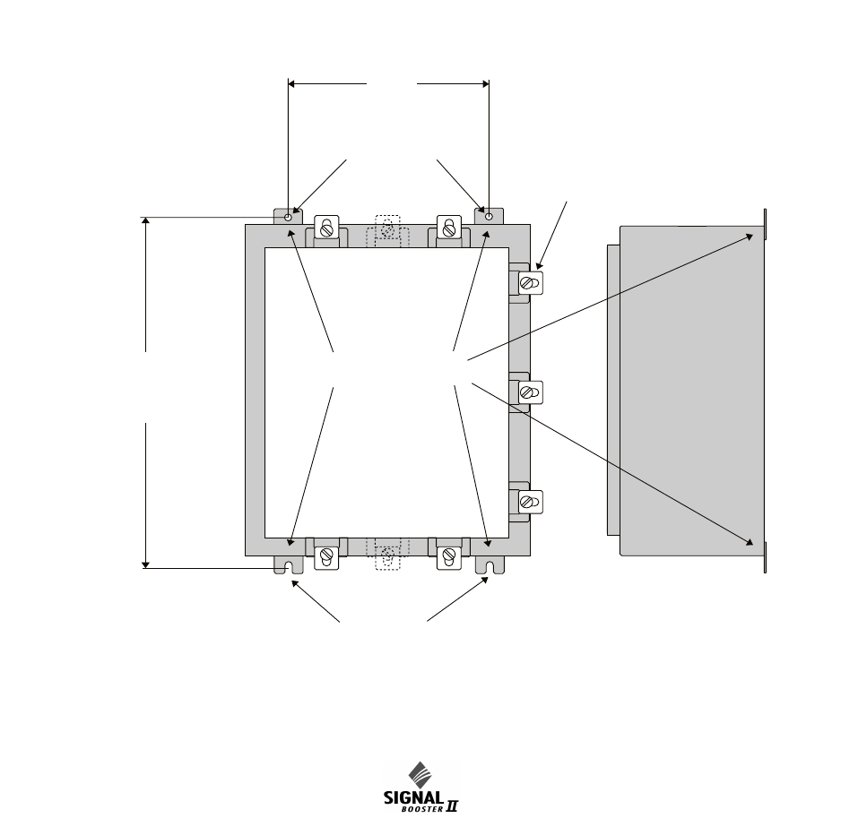
Mounting
Figure 1 shows mounting hole dimensions and lay-
out for the cabinet. Mount the cabinet using 3/8”
(10 mm) diameter steel bolts (not supplied). We
recommend flat washers on both ends and a lock
washer under the nut. Nut and bolt mounting is pre-
ferred to the use of lag bolts. Use backer blocks
where necessary to spread the force over a larger
surface area. In areas of known seismic activity,
additional devices such as tether lines may be nec-
essary.
Because TX RX Systems, Inc. cannot anticipate all
the possible mounting locations and structure
types where these devices will be located, we rec-
ommend consulting local building inspectors, engi-
neering consultants or architects for advice on how
to properly mount objects of this type, size and
weight in your particular situation.
MOUNTING TABS
DOOR
CLAMPS
0.433" DIA.
(11mm)
0.433" DIA.
(11mm)
SIDE VIEW
24.0" (610mm)
OR
18" (458mm)
37.25" (946mm)
OR
31.26" (794mm)
Figure 1: SB II cabinet mounting hole layout.
Manual 7-9386-1 Page 10TX RX Systems Inc. 09/30/04
61-68-50 UserMan page 10 of 25
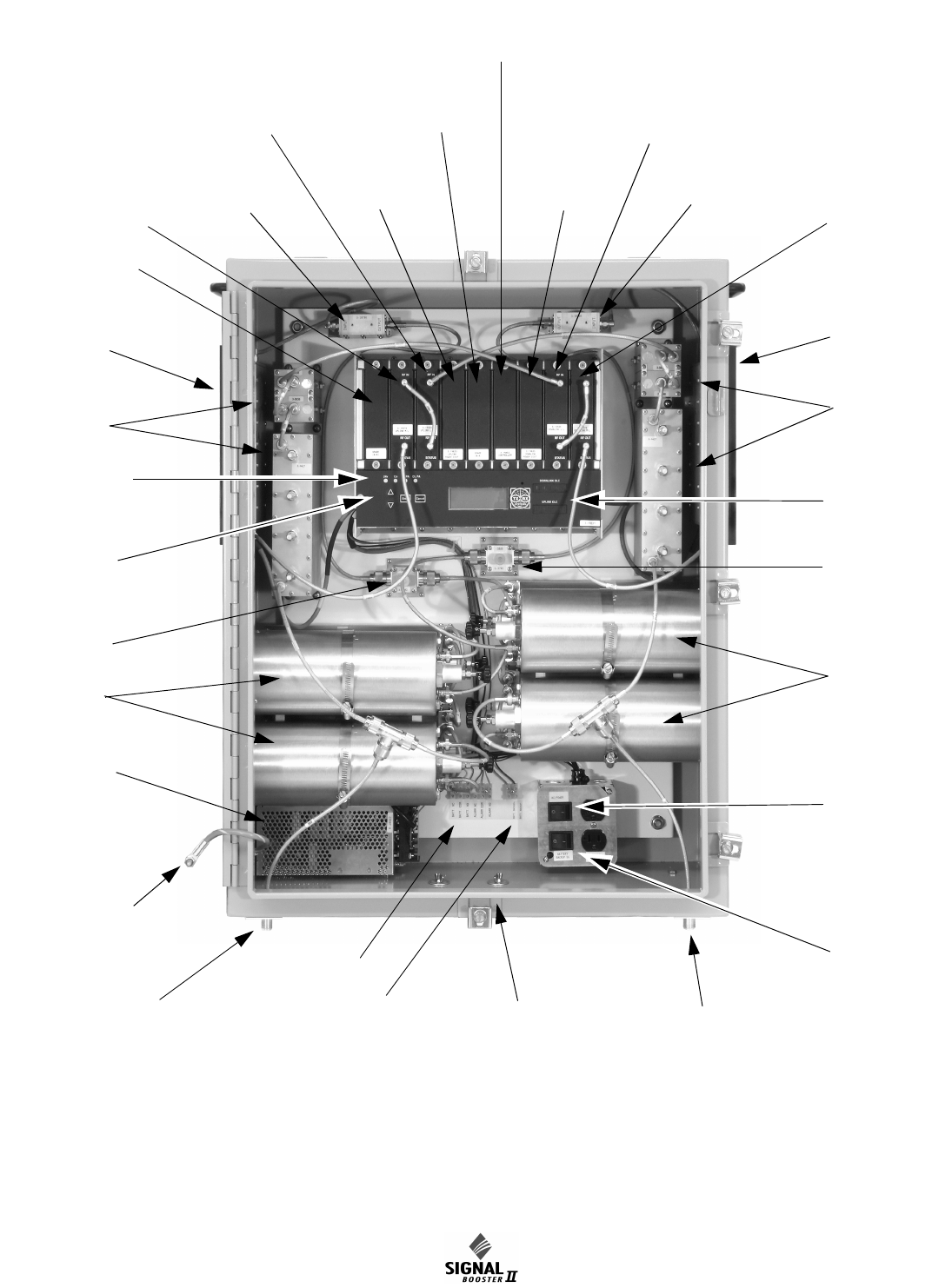
AC Power
Entry
Uplink Out
Downlink In
Connect Backup
Battery here
Form-C
Contacts
Downlink In
Uplink Out
Battery
Backup
Switch
AC Power
Switch
OLC Light
Bars
Power
Supply
Ground Strap
to
Cabinet Door
Menu
Select
Buttons
Duplexer
Signal
Sampler
Status LED’s
Filters
Uplink
Power
Amplifier
Filters
Downlink
Power
Amplifier
Duplexer
Signal
Sampler
Spare
(unused slot)
Isolator Isolator
Downlink M/L Card
(for full gain model)
Downlink Low Gain Card
(for mid gain Model)
Downlink Attenuator Card
(for low gain Model)
Uplink L/L Card
(for high gain model)
Uplink Low Gain Card
(for mid gain model)
Uplink Attenuator Card
(for low gain model)
Uplink
Power
Distribution
Uplink M/L Card
(for full gain model)
Uplink Low Gain Card
(for mid gain Model)
Uplink Attenuator Card
(for low gain Model)
Downlink L/L Card
(for high gain model)
Downlink Low Gain Card
(for mid gain model)
Downlink Attenuator Card
(for low gain model)
Downlink
Power
Distribution
Controller
Comm-Card
(optional)
Figure 2: Front view of SB II. Part number 61-68-50 two-way signal booster shown as an example.