Bird Technologies Group 5PI616850 SIGAL BOOSTER 2 User Manual 9386S1 1
Bird Technologies Group SIGAL BOOSTER 2 9386S1 1
Contents
- 1. USERS MANUAL 1
- 2. USERS MANUAL 2
- 3. USERS MANUAL 3
- 4. USERS MANUAL 4
USERS MANUAL 3
Manual 7-9386-1 Page 11TX RX Systems Inc. 09/30/04
61-68-50 UserMan page 11 of 25
It is the customer’s responsibility to make sure
these devices are mounted safely and in compli-
ance with local building codes.
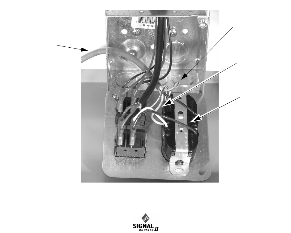
CONNECTIONS
All cabling connections to the booster should be
made and checked for correctness prior to power-
ing up the system.
AC Line
Signal Booster II is designed to be hard-wired to
110 single phase AC lines at 50 - 60 Hz (see Fig-
ures 2 and 3). A junction box is provided for this
purpose. There is a hole provided in the cabinet
bottom-wall for bringing in the AC line. The entry
box contains a standard two-receptacle AC outlet
that serves as a junction for the incoming line and
also provides a convenient AC outlet for running
test equipment. See figure 3 below. Use conduit for
running the wiring into SB II and #14 gauge or
larger conductors.
Backup DC Power
SB II may be run on a DC power source that can
supply 24 to 30 volts DC at 2.5 amps. Screw termi-
nals are provided for this purpose (see figure 2).
This line should be equipped with a fast-acting 3
Amp fuse. Use #16 or #18 gauge wire for this con-
nection.
The power system in SB II automatically switches
to this backup DC input when the AC supply fails
for any reason including a power outage or inten-
tional disconnection.
It is not necessary that this connection be made for
normal operation on the AC line.
Alarm Terminals (Form-C contacts)
Two sets of contacts are provided to monitor the
general operating condition of SB II and are
intended for connection to a supervisory system.
See figure 2.
One set changes state when the AC power supply
shuts down for any reason and the unit switches to
operation on the backup DC power system.
The other set of contacts changes state when any
of a number of fault conditions arises within the
electronics such as current drain outside of the
expected operating range in some module.
Figure 3: Wiring of AC line entry.
AC Line
Ground Wire
(green or
green/yellow)
Neutral Wire
(white)
Hot Wire
(black)

Manual 7-9386-1 Page 12TX RX Systems Inc. 09/30/04
61-68-50 UserMan page 12 of 25
A six-terminal strip is provided for the interface and
uses screw terminals for ease of connection. Route
the alarm wires through one of the access holes in
the bottom of the box, strip about 3/16” of insula-
tion from each end, loosen the screw terminal,
insert and retighten. Use #20 or #22 gauge insu-
lated wire.
Use of these terminals is optional. SB II also has a
number of status LEDs built-in to individual mod-
ules to indicate a fault condition.
RF Connections
N(F) bulkhead connectors are provided on the bot-
tom of the cabinet for connection to the signal dis-
tribution system. Be sure that the correct branch of
the distribution system is connected to its corre-
sponding Uplink/Downlink connector or the system
will not work properly. Using high-quality connec-
tors with gold center pins is advised. Flexible
jumper cables made of high-quality coax are also
acceptable for connecting to rigid cable sections.
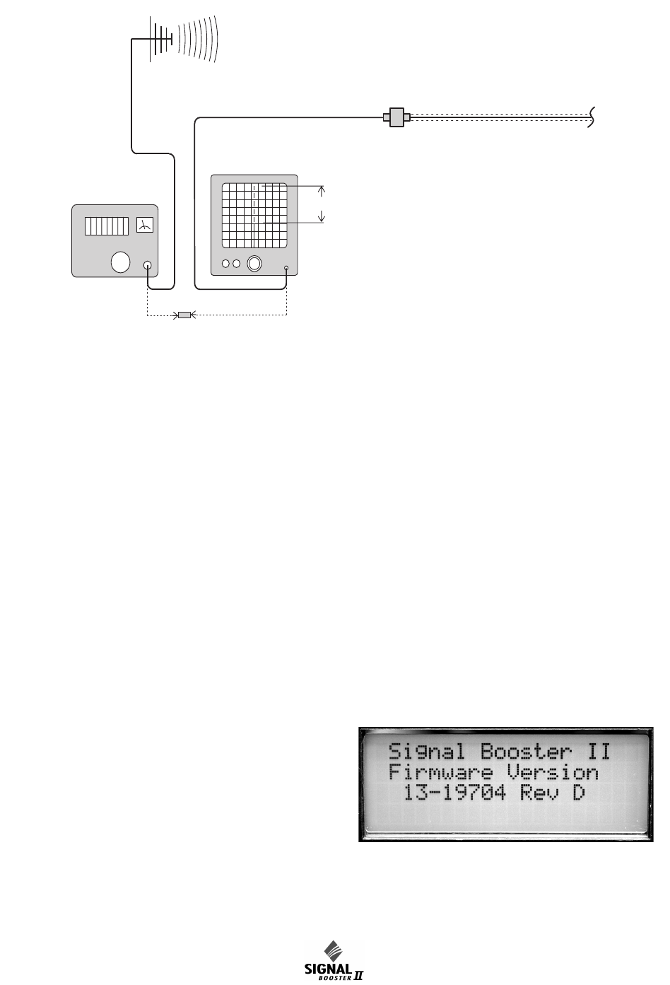
PRE-RF CONNECTION TESTS
Antenna isolation between the uplink and downlink
branches should be measured before connecting
the signal booster to the antenna system. This step
is necessary to insure that no conditions exist that
could possibly damage the signal booster and
should not be skipped for even the most thoroughly
designed system.
Note: The 80 dB gain models are fac-
tory preset to 50 dB gain and should
only be reset to a higher value after
determining the safe maximum gain
based on antenna isolation
Test Equipment
The following equipment is required in order to per-
form the pre-installation measurements.
1) Signal generator for the frequencies of interest
capable of a 0 dBm output level. Modulation is
not necessary.
2) Spectrum analyzer that covers the frequencies
of interest and is capable of observing signal
levels down to -100 dBm or better.
3) Double shielded coaxial test cables made from
RG142, RG55 or RG223 coaxial cable.
Antenna Isolation
Just like the feedback squeal that can occur when
the microphone and speaker get too close to each
other in a public address system, a signal booster
can start to self oscillate. This can occur when the
isolation between the input antenna or signal
source and the output distribution system does not
exceed the signal boosters gain by at least 15 dB.
Oscillation will reduce the effectiveness of the sys-
tem and may possibly damage the power amplifier
stages.
In general, if one or both antenna ports are con-
nected to sections of radiating coaxial cable (lossy
cable) the isolation will be more than adequate
because of the high coupling loss values that are
encountered with this type of cable. When a net-
work of antennas are used for the input and output,
this problem is much more likely. Isolation values
are relatively easy to measure with a spectrum
analyzer and signal generator.
Procedure for Measuring Antenna Isolation
1) Set the signal generator for a 0 dBm output
level at the center frequency of the signal boost-
ers passbands.
2) Set the spectrum analyzer for the same center
frequency and a sweep width equal to or just
slightly greater than the passband chosen in
step one.
3) Connect the test leads of the signal generator
and the spectrum analyzer together using a
female barrel connector, see Figure 4. Observe
the signal on the analyzer and adjust the input
attenuator of the spectrum analyzer for a signal
level that just reaches the 0 dBm level at the top
of the graticule.
4) Referring to figure 4, connect the generator test
lead to one side of the signal distribution system
(external antenna) and the spectrum analyzer
lead to the other (internal distribution system)
and observe the signal level. The difference
between this observed level and 0 dBm is the
isolation between the sections. If the signal is
too weak to observe, the spectrum analyzer's
bandwidth may have to be narrowed and its
input attenuation reduced. Record the isolation
value. The isolation value measured should
exceed the signal booster’s gain figure by at
least 15 dB.
NOTE
Manual 7-9386-1 Page 13TX RX Systems Inc. 09/30/04
61-68-50 UserMan page 13 of 25
It is wise to repeat the procedure listed above for
measuring antenna isolation with the signal gener-
ator set to frequencies at the passbands edges in
order to see if the isolation is remaining relatively
constant over the complete width of the passband.
Repeat the isolation measurements at the other
passband in bi-directional systems and use the
lesser of the two values to determine the maximum
gain setting.
Increase Isolation or decrease gain?
Modification of the signal distribution system is
required to increase isolation between the up and
downlink path. This will require significant changes
that may or may not be practical from a cost or
logistical standpoint. Gain reduction may be the
only alternative but this is easy to achieve with Sig-
nal Booster II. Gain for both the uplink and down-
link path can be set from 50 to 80 dB. Here are the
steps to follow.
1) Subtract 15 dB from the measured isolation
between uplink and downlink branches of the
antenna/signal distribution system. This is the
maximum usable gain level for both the uplink
and downlink path.
2) Accessing the user menu through the front
panel, set the gain of the uplink path to the level
determined in step 1. A detailed explanation of
how to negotiate the menu system is given on
page 9.
3) Repeat step 2 for the downlink path.
NORMAL OPERATION
Power is applied to the signal booster by turning on
the AC power switch located on the junction box
inside the cabinet, refer to figure 2. The following
startup sequence occurs.
INTERNAL
SIGNAL DISTRIBUTION
SYSTEM
SPECTRUM
ANALYZER
EXTERNAL
ANTENNA
SIGNAL
GENERATOR
ZERO LOSS
REFERENCE
ISOLATION (dB)
Figure 4: Typical test equipment interconnection for measuring antenna isolation.
Figure 5: Software version is displayed briefly
during the boot-up sequence.
Manual 7-9386-1 Page 14TX RX Systems Inc. 09/30/04
61-68-50 UserMan page 14 of 25
1) At turn-on, the four status LEDs on the front
panel glow red for about 5 seconds as the result
of entering a self-check mode.
2) The two green OLC light bars will be fully lit
along their length for approximately 5 seconds.
3) The LCD display shows the firmware revision
screen for about 5 seconds (see Figure 5).
4) After the self check is complete, the four status
lights should turn green and the light bars
should be dark unless a signal is activating OLC
action in either the uplink or downlink.
If the OLC light-bar segments on both the Uplink
and Downlink display light-up and pulse on and off
every 1 to 3 seconds simultaneously, SHUT OFF
THE POWER IMMEDIATELY! The booster may be
oscillating. Disconnect the uplink and downlink
antenna connections and measure the isolation
between the two branches to insure there is suffi-
cient isolation. Reset the booster gain as needed.
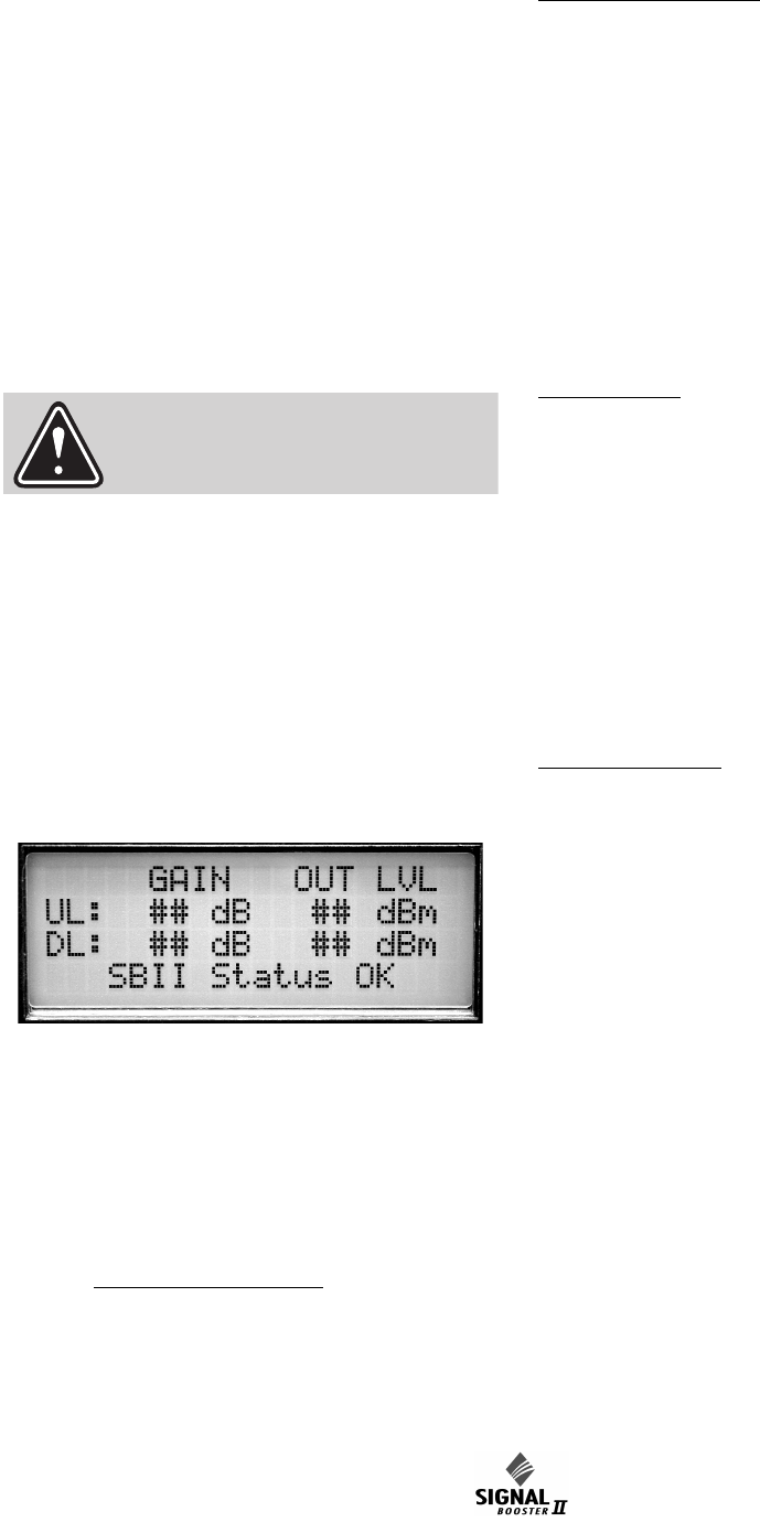
5) The LCD display should appear similar to Fig-
ure 6 after the self check is complete.
LED Status indicators
The SB II front panel has 4 status LEDs that glow
green or red to indicate the general health of 4 sub-
systems from a DC perspective. Additionally, the
plug-in, Low-Level and Mid-Level amplifier cards
have tri-color (green-orange-red) status LEDs visi-
ble when the cabinet door is open.
FRONT PANEL LEDS:
24V: Green indicates the 24 volt DC Power system
is operating properly.
12V: Green indicates the 12 volt DC power system
is operating properly.
UL PA: Green indicates that the uplink power
amplifier is drawing current within the expected
operating range and at a safe temperature.
DL PA: Green indicates that the downlink power
amplifier is drawing current within the expected
operating range and at a safe temperature.
Module LEDS;
Mid-Level, Low-Level, Low Gain Module: Green
indicates current or device temperature within the
expected operating range. Orange indicates cur-
rent or temperature slightly out of the expected
range but the overall booster operation may still
appear normal. Red indicates a large departure
from normal current or device temperature and
booster operation is likely to be affected. See page
11 for more details about alarm operation.
Attenuator Module: Green only indicating DC
power is applied to the card.
OLC LIGHT BARS
Ideally, there should be little or no light bar activity.
Each light bar segment represents an average 3
dB of OLC gain reduction. OLC (output level con-
trol) is meant to reduce gain for transient episodes
of very strong signals. However, when OLC is
active, gain is reduced for all signals being pro-
cessed by that booster branch and that reduction
may compromise communications for weaker sig-
nals in the booster’s passband.
If more than 2 or 3 light-bar segments are lit up
more than occasionally, it is advised that the gain
of that branch be reduced. See the SET GAIN
paragraph on page 10 for details.
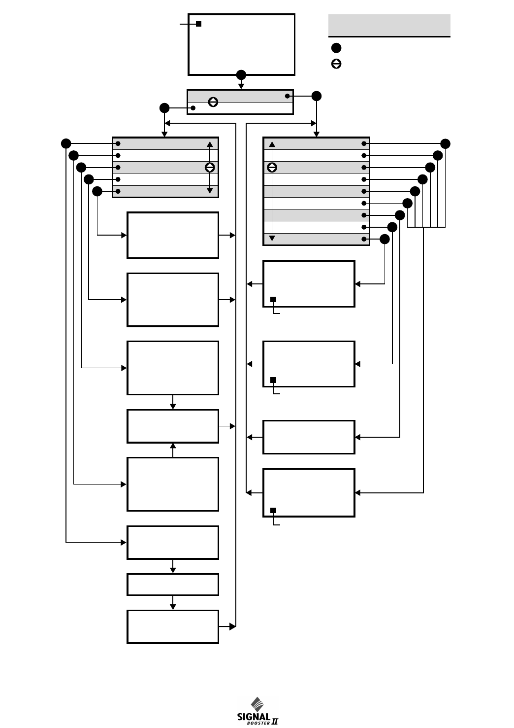
Front Panel Controls & the LCD Display
SB II is software directed so control of the system
is accomplished via user interface with the control
panel using the LCD display screen and the menu
select buttons, see figure 2. A flow chart showing
all of the possible user menu selections is shown in
Figure 7.
WARNING
Figure 6: Normal Operational LCD Display.
Manual 7-9386-1 Page 15TX RX Systems Inc. 09/30/04
61-68-50 UserMan page 15 of 25
GAIN
## dB
## dB
OUT LVL
## dBm
## dBm
UL:
DL:
SBII Status OK
Calibrate Currents
Set Gain
Set Output Level
Change Gain Config
Restore Orig Config
Uplink Low Level Amp
Uplink Mid Level Amp
Uplink Power Amp
Downlink Low Amp
Downlink Mid Amp
Downlink Power Amp
Power Supply
Current OLC Status
OLC Historical Info
OLC Historical Info
Avg
# dB
# %
Day
# dB
# %
UL
Current OLC Status
Uplink
# dB
# %
Downlink
# dB
# %
Name of Amp
Current # Temp #
Amp Status Message
Power Supply Status
24v ### 12v ###
Set Desired Gain
Uplink
## dB
Downlink
## dB
Done
Save Changes?
Yes No
Uplink
## dBm
Downlink
## dBm
Done
Set Output Levels
UL >
DL >
_ _ _ _ Gain ## dB
_ _ _ _ Gain ## dB
Done
Change Gain Config
Are you sure
you want to restore
the Factory Presets?
Yes No
Press Enter to
Calibrate Currents
Calibrating . . .
Done Calibrating
Press Enter to Save
Press ENTER key
KEY
SBII USER MENU 1 (8-20460B)
Press Item Select arrow key
E
EE
E
E
E
E
E
E
E
E
E
E
E
E
E
E
E
Detailed Status
Configuration
NOTE:
Press ENTER
to see Downlink
NOTE:
Button press required
to exit this display
NOTE:
Pressing CANCEL always returns
you to the previous menu without
saving changes
NOTE:
If no button is pressed within
2 minutes, system returns to
Main Status Display Screen
NOTE:
This menu screen will also give you
the option to place an amplifier into
Bypass or take one out of Bypass.
Figure 7: Signal Booster II Menu System.

Manual 7-9386-1 Page 16TX RX Systems Inc. 09/30/04
61-68-50 UserMan page 16 of 25
LCD Screen
Once the boot-up sequence is completed (after
several seconds) the LCD screen will switch to the
main status display as shown in figure 6. This is the
normal display for the signal booster. The system
will return to this display from any other display if
none of the menu interface buttons are pressed
within 2 minutes. The exception is the OLC status
display which does require a button press to exit.
The main status display shows the uplink and
downlink gain in dB as well as the uplink and down-
link output level in dBm.
The last line of the main status display gives a
summary status message for the entire signal
booster. In this example “Status OK” is being dis-
played. Pressing the “ENTER” button will move you
from the main status display into the menu selec-
tions and will permit interaction with the system.
There are two main functions available within the
software menus including configuration settings
and detailed status displays.
Configuration Settings
In most cases, the factory default settings are the
optimum values for adjustable parameters. The
most common setting to be changed by the sys-
tem’s technician is the gain setting. This is normally
done to compensate for varying values of antenna
isolation as outlined earlier in this manual or to
reduce excessive OLC action resulting from exces-
sive gain.
Please thoroughly study this section before making
any adjustments to the configuration values. Each
configured item is discussed in detail.
Note: Changes to configuration set-
tings do not take affect until the Main
Status screen is re-enabled. This
occurs automatically after 2 minutes
without button input or manually by
pressing the Enter/Done/Cancel buttons to return
to the status screen.
RESTORE ORIG CONFIG
This command will restore all configured settings to
their original factory default values. SB II ships from
the factory preset to the lowest gain possible.
CALIBRATE CURRENTS
Use this command when replacing an RF amplifier.
This function automatically calibrates the current
alarm “trip” point of each amplifier in the system.
Due to manufacturing tolerances there are small
differences in current draw between amplifier
assemblies. This software function matches the
alarm sensing circuit to the respective amplifier
assembly and should be repeated whenever an
amplifier assembly is replaced.
SET GAIN
This function allows the user to electronically set
the gain of the booster in 0.5 dB increments over a
range of 30 dB. Gain can be adjusted indepen-
dently for both the uplink and downlink channels
but in most cases both uplink and downlink should
be set to the same gain value.
Know your antenna isolation before making this
adjustment. We recommend that you temporarily
disconnect both the uplink and downlink antennas
when setting the gain to avoid the possibility of
causing the unit to oscillate. After changing the set-
ting, power the unit down, reconnect the antennas
and power-up the booster.
Note: A reduction in system gain will
also result in an equal reduction in the
OLC dynamic range, refer to the sec-
tion titled “OLC” on page 11.
SET OUTPUT LEVEL
Allows the output power for the uplink and downlink
channels to be independently adjusted in 0.5 dB
increments up to +31 dBm. Note that the OLC cir-
cuitry will maintain the systems output level at the
values you have selected in this menu.
Use this function ONLY if your system is causing
some form of interference to another radio system.
You can only reduce the booster’s output power
with this command.
CHANGE GAIN CONFIGURATION
Insures proper gain readings when changing basic
booster gain by changing the type of plug-in card
assemblies.
Use of this menu is ONLY needed when converting
your stock SB II to a different gain level by chang-
ing the low level, mid-level plug-in amplifier card or
the addition of an attenuator card. The addition of
these cards will change the unit to another model
within the UHF SB II family, see table 2. Don’t con-
fuse this with simple amplifier bypassing to reduce
gain. Uplink and down link can be set indepen-
NOTE
NOTE

Manual 7-9386-1 Page 17TX RX Systems Inc. 09/30/04
61-68-50 UserMan page 17 of 25
dently. Choices for gain are Full, Mid or Low and
the ENTER key toggles the gain setting. The corre-
sponding gain level is displayed. Select DONE
using the arrow keys and press ENTER to return to
the menu. Use the CANCEL button to return to the
Status Display.
Detailed Status Screens
These items allow a detailed examination of sys-
tem components including; all amplifiers (current
draw and temperature), the power supply (voltage
level), and the OLC function (present status and
historical archive). Each item is discussed below in
detail.
AMPLIFIERS
A separate status screen is available for each
amplifier in the system. When an amplifier is
selected this function will display the present cur-
rent draw of that amp as well as its present operat-
ing temperature in degrees Celsius. In addition, a
status message will indicate if the amplifier is con-
nected and whether the amplifier is bypassed or
not bypassed. This menu selection also provides
the option of placing an amplifier in bypass or tak-
ing an amplifier out of bypass.
The current draw will be blank if an amplifier is not
connected, will display BYP if the amplifier is
bypassed, and will display ATTEN if an attenuator
card is being used in place of the amplifier card.
The power amplifier currents will nor-
mally fluctuate up to 850 ma when sig-
nals are present.
POWER SUPPLY
This function displays the real time power supply
voltages for both 24 volt and 12 volt supplies.
OLC
This screen shows the amount of attenuation pres-
ently being used by the OLC for both the uplink and
downlink channels. In addition, the percentage of
OLC presently being used is also shown.
The amount of OLC currently being
used in either the uplink or downlink
channels is also indicated by LED bar
graph displays located on the display
panel. Each segment represents 2 to
4 dB of attenuation depending on the gain setting
of the booster. The OLC bars should only be active
occasionally and no more than 3 or 4 segments
briefly lit. Constant light bar activity means the
booster gain needs to be reduced for optimum per-
formance.
The system has 60 dB of OLC
dynamic range. However, the
dynamic range of the OLC is reduced
when the user selectable gain is
reduced. The reduction will be an
equal amount. For instance, if the user selectable
gain is reduced by 20 dB then the OLC dynamic
range will also be reduced by 20 dB.
OLC DATALOG
This screen displays an OLC Datalog which is the
OLC data over the past 100 days for both uplink
and downlink branches of the system. This is a roll-
ing 100 day log with day 101 overlapping day 1 and
so forth. Day zero represents the current day while
day one represents yesterday and so on. The
logged data is stored in non-volatile memory and
will not be erased when the unit is powered down.
The average OLC attenuation used when the OLC
was active is given both for individual days and
over the entire past 100 days. The percentage of
time the OLC was active is also given for both indi-
vidual days and over the past 100 days. This
archived information will permit the creation of a
user signal profile to facilitate optimum system con-
figuration and performance.
This archive feature will allow you to see if the gain
of the unit is set too high or if there are transient
episodes of strong signals perhaps desensing
other channels being amplified by the booster.
Alarms
The system continuously monitors the current draw
and operating temperature of each amplifier as well
as the voltage level of the +12 and +24 VDC sup-
plies. If any of these parameters exceed normal
operating levels by a factory preset percentage the
system enters an alarm condition. Notification of an
alarm condition is provided by LED indicators and
Form-C contacts available via the alarm terminal
screws.
NOTE
NOTE
NOTE