Bird Technologies Group 5PI616850 SIGAL BOOSTER 2 User Manual 9386S1 1
Bird Technologies Group SIGAL BOOSTER 2 9386S1 1
Contents
- 1. USERS MANUAL 1
- 2. USERS MANUAL 2
- 3. USERS MANUAL 3
- 4. USERS MANUAL 4
USERS MANUAL 4
Manual 7-9386-1 Page 18TX RX Systems Inc. 09/30/04
61-68-50 UserMan page 18 of 25
LED INDICATORS
There are LED indicators for each amplifier in the
system as well as the +12 and +24 VDC power
supply voltages. The LED indicators for the low,
mid, and low gain amplifiers are located on the
individual plug-in module. These are tri-color LED’s
with green representing NORMAL operation,
orange representing a WARNING condition, and
red indicating a FAULT. A warning condition occurs
when the current draw of the amplifier exceeds
nominal by +/- 20%. Fault conditions occur when
the current draw exceeds +/- 30% or the amplifiers
operating temperature exceeds 80° Celsius. The
LED for the attenuator card is green only and indi-
cates DC power applied to the card.
The LED indicators for the power amplifiers are
located on the display panel next to the menu
select buttons and are dual color LED’s. Green rep-
resents NORMAL operation while red indicates a
FAULT condition. Fault conditions occur when the
current draw exceeds 900 ma or falls below 200
ma. Also, whenever the amplifiers operating tem-
perature exceeds 95° Celsius. The power amplifi-
ers do not have a warning state.
The power supply LED indicators are located on
display panel next to the menu selection buttons
and are also dual color. Green representing normal
operation and red a fault condition. A fault condition
for the +24 VDC supply occurs whenever the volt-
age potential drops below +16 VDC (30% below
nominal). Likewise, a fault for the +12 VDC supply
occurs when the potential is below +8 VDC (30%
below nominal).
FORM-C CONTACTS
Form-C contacts are available inside the cabinet
next to the power supply assembly, see figure 2.
These screw terminals are intended for connection
to the customers supervisory alarm or data acqui-
sition system. One set of terminals supplies notifi-
cation of any alarm condition occurring and the
second set of contacts indicate the system is oper-
ating on battery backup power.
PERFORMANCE SURVEY
It is a good idea to document the performance of
the system after installation so that a reference
exists for future comparisons. This information can
make troubleshooting an interference problem or
investigation of a complaint about system perfor-
mance much easier. If there are coverage prob-
lems with a system, this survey will usually reveal
them allowing corrective measures to be taken
before the system is put into routine use. The fol-
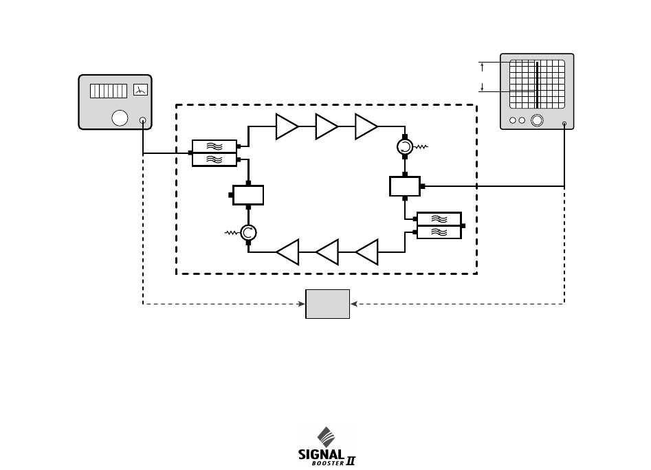
Signal
Generator
Zero
Reference
Spectrum
Analyzer
Gain
Sample
Sample
Test Port
Test Port
Figure 8: Measuring signal booster gain.
Manual 7-9386-1 Page 19TX RX Systems Inc. 09/30/04
61-68-50 UserMan page 19 of 25
lowing is an outline of how to do such a survey.
Because the nature of each installation can be
quite different, only a broad outline is given.
1) Measure the gain of the signal booster being
careful not to exceed the maximum input level.
Figure 8 shows this being done using a signal
generator and spectrum analyzer. Record the
measured values for each passband. We rec-
ommend that a 50 ohm load be connected to
the unused RF port on the bottom of the cabinet
during the gain test.
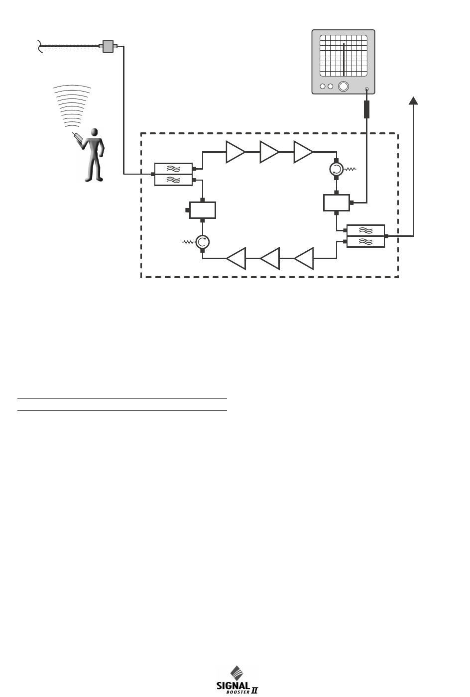
2) The spectrum analyzer is connected to the -30
dB signal sampler port following the final output
amp. This port will allow the observation of the
amplifier output at a considerably reduced out-
put level. This decoupling value (-30 dB) needs
to be added to any measured signal value in
order to arrive at the actual signal level.
3) With a spectrum analyzer connected to the sig-
nal sampler port (see Figure 9), have person-
nel with handheld radios move to several
predetermined points and key their radios.
Record the level of these signals as observed
on the analyzer and also record the location of
the person transmitting. In this way, a map of
the systems performance can be generated.
4) For signals coming from a fixed antenna or sta-
tion, record the level of all the desired incoming
signals for future reference.
MAINTENANCE AND REPAIR
Signal boosters manufactured by TX RX Systems,
Inc. can perform for years with little maintenance
and repair. However, if the amplifiers are subjected
to excessively high signal levels, power surges or
lightning strikes, failures may occur. The following
procedures may be followed for detecting a mal-
functioning unit or as part of a periodic mainte-
nance program.
1) The heatsink area should be cleared of dust
and debris.
2) Inspect the unit to see that the two power sup-
ply LED DC indicators are lit (remove any dust
or debris that may obscure the LEDs). This will
Boosted
RF Signal
Signal Distribution System
Spectrum
Analyzer
10 dB Pad
Sample
Sample
Test Port
Test Port
Figure 9: Methodology for doing a performance survey of the signal distribution system.

Manual 7-9386-1 Page 20TX RX Systems Inc. 09/30/04
61-68-50 UserMan page 20 of 25
verify that DC power is flowing properly. Check
all hardware for tightness.
3) Compare system performance to initial perfor-
mance levels measured when the system was
first installed. The lack of signal can be traced to
a malfunctioning amplifier by progressive signal
monitoring from the output (far end) to the input
end of the system noting the area where the
signal returns to normal level. The next amplifier
toward the output end of the system will proba-
bly be the one that failed.
or
Measure the gain at any convenient frequency
in the working frequency band to verify that the
performance is still within specifications.
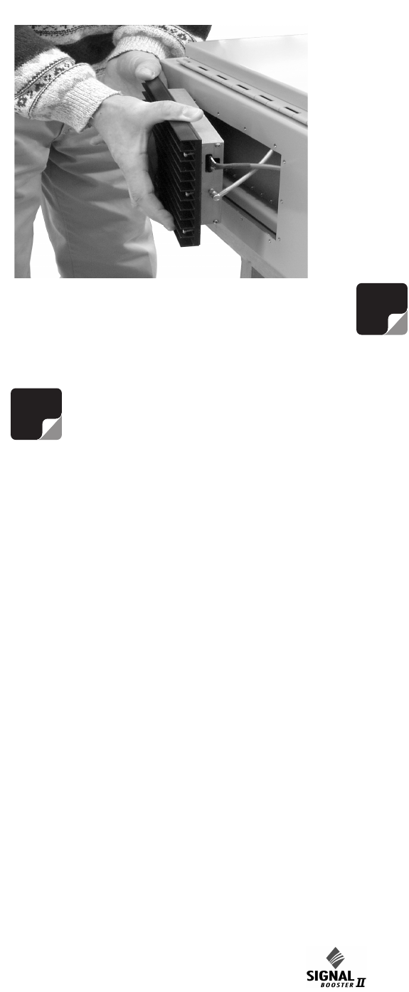
Power Amplifier Replacement
The SB II power amplifiers are field replaceable.
Follow the steps listed below in sequential order.
The required tools are a #1 Phillips screwdriver
and a 5/16” open-ended wrench.
Figure 10: Remove 14 mounting screws to detach amplifier assembly from cabinet.
Remove Screws
Remove Screws
Remove
Screws
Remove
Screws
Figure 11: Slide amplifier towards bottom of cabi-
net to remove upper cable.
Manual 7-9386-1 Page 21TX RX Systems Inc. 09/30/04
61-68-50 UserMan page 21 of 25
Note: Power to the SB II cabinet must
be turned OFF during the power
amplifier replacement process.
1) Remove the Phillips screws which hold the
amplifier into place, refer to Figure 10. The nuts
holding the screws are pressed into the cabinet
and will remain in place when the screws are
removed.
2) Slide the amplifier towards the bottom of the
cabinet as far as it will go. This will allow the top
RF connector to clear the opening. Tilt the top
of the amplifier outwards and remove the top
RF cable at the SMA connector using the 5/16”
wrench. See Figure 11.
3) Slide the amplifier assembly towards the top of
the cabinet as far as it will go. This will allow the
bottom RF connector and grey control cable to
clear the opening. Tilt the bottom of the ampli-
fier outwards and remove the bottom RF cable
at the SMA connector and the grey control
cable. To remove the grey cable from the socket
on the amplifier it is necessary to squeeze the
top and bottom of the connector together to
release a hold down tab. When properly
squeezed the grey cable will disconnect easily
from the amplifier. Refer to Figure 12.
4) To replace the amplifier assembly repeat steps
1 through 3 in reverse order. When replacing
the RF cables do not overtighten the SMA con-
nectors. They should be tightened just slightly
more than hand tight or to the specification of 7
in/lbs. The replacement amplifier comes with an
attached gasket which must press up against
the outside of the cabinet firmly and squarely in
order to provide a correct moisture seal.
Module Replacement
The SB II modules are field replaceable. Follow the
steps listed below in sequential order. The required
tools are a #1 Phillips screwdriver. Two thumb
screws hold each module into place.
Note: Power to the SB II cabinet must
be turned OFF during the module
replacement process except for the
amplifier modules which are “HOT”
switchable.
1) Loosen the two thumb screws which hold the
module into place. Phillips screws are incorpo-
rated into the thumbscrews and they may need
to be loosened first.
2) Grasping the two loosened thumb screws pull
the module straight out of the card cage.
3) To install the replacement module place the
module into the guide-rails of the slot and press
down firmly into place. Each type of module is
keyed uniquely to fit in only one slot within the
card cage. Once the card is seated into place
properly tighten the thumb screws.
The SB II low level and mid level amplifier stages
are field replaceable by simply removing the mod-
ule and plugging in a replacement. These modules
are HOT switchable meaning they can be swapped
without powering down the system. RF cables
attached to the modules must be removed (5/16”
wrench) prior to swapping the modules and must
be re-attached after the new module is in place.
when replacing the RF cables do not overtighten
the SMA connectors. They should be tightened just
slightly more than hand tight or to the specification
of 7 in/lbs.
NOTE
NOTE
Figure 12: Slide amplifier towards top of cabinet to
remove lower cables.
Manual 7-9386-1 Page 22TX RX Systems Inc. 09/30/04
61-68-50 UserMan page 22 of 25
Modules can be swapped between the uplink and
downlink branches for troubleshooting purposes. If
a problem exists in one branch and the problem
moves to the other branch when modules are
swapped around this indicates a defective module.
Note: After an amplifier module is
replaced use the Calibrate Currents
software function to properly set the
amplifiers alarm trip point, see page
10. Due to slight differences in compo-
nent tolerances the trip point must be reset for any
new amplifier assemblies introduced into the sys-
tem.
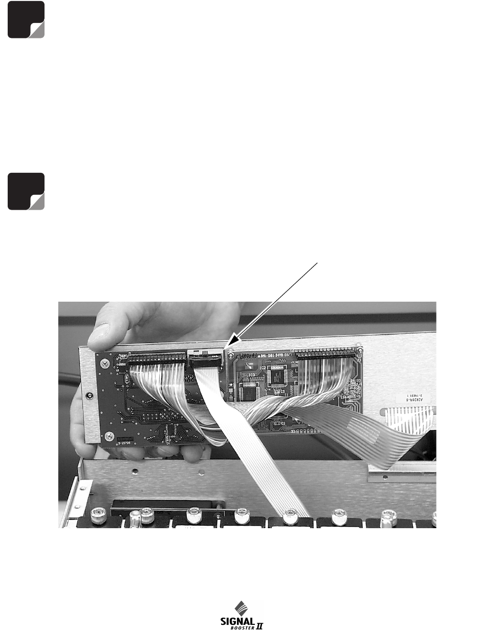
Display/User Interface Assembly Replacement
The SB II Display/User Interface assembly is field
replaceable. Follow the steps listed below in
sequential order. No tools are required.
Note: Power to the SB II cabinet must
be turned OFF during the display/user
interface replacement process.
1) Loosen the two thumb-nuts which hold the dis-
play/user interface assembly to the card cage.
2) Gently tilt only the top of the assembly up from
the card cage. Keep the bottom of the assembly
in place. The bottom mounting plate (part of the
card cage) has an overhang on it to support the
display/user interface board. If the assembly is
lifted straight out the overhang could possibly
damage the interface circuit board.
3) With the display/user interface board standing
up straight gently move it upwards while lifting it
out about an inch or two. This should allow the
overhang to clear the interface circuit board
without damage.
4) Remove the ribbon cable that connects the dis-
play/user interface assembly to the card cage,
see Figure 13.
5) To replace the display/user interface assembly
repeat steps 1 through 4 in reverse order.
NOTE
NOTE
Figure 13: Disconnecting the display/user interface assembly from the card cage.
Disconnect
ribbon cable
here

Manual 7-9386-1 Page 23TX RX Systems Inc. 09/30/04
61-68-50 UserMan page 23 of 25
Power Supply Replacement
The SB II power supply assembly is field replace-
able. Follow the steps listed below in sequential
order. The required tools are a #1 Phillips screw-
driver.
1) Turn off AC power at the junction box.
2) Disconnect the 3 conductor cable that brings
AC power to the supply from the junction box.
3) Disconnect the red and black leads from the
power supply that connect to the card cage.
4) Remove the Phillips screws that hold the power
supply mount bracket to the back plate and
remove the assembly from the cabinet.
5) Reverse steps 4 through 2 to install the replace-
ment power supply.
Duplexer / Filter Replacement
The component assemblies of the duplexer are
field replaceable. Follow the steps listed below in
sequential order. The required tools are a #1 Phil-
lips screwdriver with an extended shaft to reach
down far enough into the unit to loosen mounting
screws.
Note: Power to the SB II cabinet must
be turned OFF during the assembly
replacement process.
1) All RF cables attached to the assembly must be
removed.
2) Remove the Phillips screws that hold the
assembly mount brackets to the back plate and
remove the assembly from the cabinet.
3) Reverse steps 2 and 1 to install the replace-
ment assembly. When replacing the RF cables
do not overtighten the SMA connectors. They
should be tightened just slightly more than hand
tight or to the specification of 7 in/lbs.
Card Cage Replacement
To replace the card cage follow the steps listed
below in sequential order. The required tools are a
#1 Phillips screwdriver with an extended shaft to
reach down far enough into the unit to loosen the
mounting screws.
Note: Power to the SB II cabinet must
be turned OFF during the card cage
replacement process.
1) Disconnect the display/user interface assembly.
2) Disconnect 4 cables at the backplane of the
card cage which are assessable with the dis-
play/user interface board out of the way.
3) Remove the row of Phillips screws which hold
the card cage to the back plate. There is a row
of screws at the top and bottom of the cage.
4) To install a replacement cage perform steps 3
through 1 in reverse order.
RECOMMENDED SPARES
It is recommended that one spare of each of the
following assemblies be kept on hand for emer-
gency repair purposes; Power Supply 8-20667,
Uplink/Downlink Power Amplifier either 3-20806, 3-
20807, 3-20303, or 3-20628 (depending on the
specific model of UHF SB II), Mid Level Amplifier
Card 3-19576, Low Level Amplifier Card 3-19935,
Low Gain Amplifier Card 3-20294, Attenuator Card
3-20208, Power Distribution Card 3-19833, Con-
troller Card 3-19832, and the Display/User Inter-
face Assembly 3-19831.
NOTE
NOTE
Manual 7-9386-1 Page 24TX RX Systems Inc. 09/30/04
61-68-50 UserMan page 24 of 25
Part Number 61-70-50-A2.0-G1 61-71-50-A0.5-G1 61-72-50-A0.5-G1
Maximum Gain: +80 dB +80 dB +80 dB
Gain Adjustment: Programmable attenuation,
0-30 dB, 0.5 dB steps
Programmable attenuation,
0-30 dB, 0.5 dB steps
Programmable attenuation,
0-60 dB, 0.5 dB steps
3rd Order Output Intercept Point: +50 dBm minimum,
with no attenuation
+50 dBm minimum,
with no attenuation
+50 dBm minimum,
with no attenuation
Max RF Power Output +32 dBm (single carrier) +32 dBm (single carrier) +32 dBm (single carrier)
RF Sampler: PA Output sampler ports PA Output sampler ports PA Output sampler ports
Noise Figure (without attenuation): 5.0 dB maximum 8.0 dB maximum 8.0 dB maximum,
Operating Temperature Range: -30°C to +50° C -30°C to +50° C -30°C to +50° C
Nominal Impedance: 50 ohms, <1.5:1 VSWR 50 ohms, <1.5:1 VSWR 50 ohms, <1.5:1 VSWR
Input/Output Connectors: N female N female N female
RF Sampler Connectors: BNC female BNC female BNC female
AC Power Input: 100-240 VAC; 50-60 Hz 100-240 VAC; 50-60 Hz 100-240 VAC; 50-60 Hz
DC Input Voltage: +24 to +30 VDC +24 to +30 VDC +24 to +30 VDC
Unit Power Consumption (AC/DC): <100 VA <100 VA <100 VA
Housing: NEMA 4, NEMA 4X
Rack Mount
NEMA 4, NEMA 4X
Rack Mount
NEMA 4, NEMA 4X
Rack Mount
Nominal Size: 36" x 30" x 12" 30" x 24" x 12" 30" x 24" x 12”
Net Weight: < 100 lbs. < 100 lbs. < 100 lbs.
Manual 7-9386-1 Page 25TX RX Systems Inc. 09/30/04
61-68-50 UserMan page 25 of 25
CELCIUS FARENHEIT
105 221.0
104 219.2
103 217.4
102 215.6
101 213.8
100 212.0
99 210.2
98 208.4
97 206.6
96 204.8
95 203.0
94 201.2
93 199.4
92 197.6
91 195.8
90 194.0
89 192.2
88 190.4
87 188.6
86 186.8
85 185.0
84 183.2
83 181.4
82 179.6
81 177.8
80 176.0
79 174.2
78 172.4
77 170.6
76 168.8
75 167.0
74 165.2
73 163.4
72 161.6
71 159.8
70 158.0
69 156.2
68 154.4
67 152.6
66 150.8
65 149.0
64 147.2
63 145.4
62 143.6
61 141.8
60 140.0
59 138.2
58 136.4
57 134.6
56 132.8
55 131.0
54 129.2
53 127.4
52 125.6
51 123.8
50 122.0
49 120.2
48 118.4
47 116.6
46 114.8
45 113.0
44 111.2
43 109.4
42 107.6
41 105.8
40 104.0
39 102.2
38 100.4
37 98.6
36 96.8
35 95.0
34 93.2
33 91.4
32 89.6
31 87.8
30 86.0
29 84.2
28 82.4
CELCIUS FARENHEIT
27 80.6
26 78.8
25 77.0
24 75.2
23 73.4
22 71.6
21 69.8
20 68.0
19 66.2
18 64.4
17 62.6
16 60.8
15 59.0
14 57.2
13 55.4
12 53.6
11 51.8
10 50.0
948.2
846.4
744.6
642.8
541.0
439.2
337.4
235.6
133.8
032.0
-1 30.2
-2 28.4
-3 26.6
-4 24.8
-5 23.0
-6 21.2
-7 19.4
-8 17.6
-9 15.8
-10 14.0
-11 12.2
CELCIUS FARENHEIT
-12 10.4
-13 8.6
-14 6.8
-15 5.0
-16 3.2
-17 1.4
-18 -0.4
-19 -2.2
-20 -4.0
-21 -5.8
-22 -7.6
-23 -9.4
-24 -11.2
-25 -13.0
-26 -14.8
-27 -16.6
-28 -18.4
-29 -20.2
-30 -22.0
-31 -23.8
-32 -25.6
-33 -27.4
-34 -29.2
-35 -31.0
-36 -32.8
-37 -34.6
-38 -36.4
-39 -38.2
-40 -40.0
-41 -41.8
-42 -43.6
-43 -45.4
-44 -47.2
-45 -49.0
-46 -50.8
-47 -52.6
-48 -54.4
-49 -56.2
-50 -58.0
CELCIUS FARENHEIT
CELSIUS TO FAHRENHEIT CONVERSION TABLE