Bird Technologies Group 5PI616850 SIGAL BOOSTER 2 User Manual 9386S1 1
Bird Technologies Group SIGAL BOOSTER 2 9386S1 1
Contents
- 1. USERS MANUAL 1
- 2. USERS MANUAL 2
- 3. USERS MANUAL 3
- 4. USERS MANUAL 4
USERS MANUAL 1
Part No.
61-68-50 UserMan page 1 of 25
Installation and Operation Manual for the
Two-Way Signal Booster System
Model Number 61-68-50
First Printing: September 2004
7-9386-1
Version Number Version Date
1 09/30/04
Copyright © 2004 TX RX Systems Inc.
61-68-50 UserMan page 2 of 25
NOTE
WARNING
Warranty
This warranty applies for one year from shipping date.
TX RX Systems Inc. warrants its products to be free from defect in material and workman-
ship at the time of shipment. Our obligation under warranty is limited to replacement or
repair, at our option, of any such products that shall have been defective at the time of
manufacture.
TX RX Systems Inc. reserves the right to replace with merchandise of equal performance
although not identical in every way to that originally sold.
TX RX Systems Inc. is not liable for damage caused by lightning or other natural disasters.
No product will be accepted for repair or replacement without our prior written approval.
The purchaser must prepay all shipping charges on returned products. TX RX Systems
Inc. shall in no event be liable for consequential damages, installation costs or expense of
any nature resulting from the purchase or use of products, whether or not they are used in
accordance with instructions. This warranty is in lieu of all other warranties, either ex-
pressed or implied, including any implied warranty or merchantability of fitness. No repre-
sentative is authorized to assume for TX RX Systems Inc. any other liability or warranty
than set forth above in connection with our products or services.
Terms and Conditions of Sale
PRICES AND TERMS: Prices are FOB seller’s plant in Angola, NY domestic packaging
only, and are subject to change without notice. Federal, State and local sales or excise
taxes are not included in prices. When Net 30 terms are applicable, payment is due
within 30 days of invoice date. All orders are subject to a $100.00 net minimum.
QUOTATIONS: Only written quotations are valid.
ACCEPTANCE OF ORDERS: Acceptance of orders is valid only when so acknowledged
in writing by the seller.
SHIPPING: Unless otherwise agreed at the time the order is placed, seller reserves the
right to make partial shipments for which payment shall be made in accordance with
seller’s stated terms. Shipments are made with transportation charges collect unless
otherwise specified by the buyer. Seller’s best judgement will be used in routing, except
that buyer’s routing is used where practicable. The seller is not responsible for selection
of most economical or timeliest routing.
CLAIMS: All claims for damage or loss in transit must be made promptly by the buyer
against the carrier. All claims for shortages must be made within 30 days after date of
shipment of material from the seller’s plant.
SPECIFICATION CHANGES OR MODIFICATIONS: All designs and specifications of
seller’s products are subject to change without notice provided the changes or modifi-
cations do not affect performance.
RETURN MATERIAL: Product or material may be returned for credit only after written
authorization from the seller, as to which seller shall have sole discretion. In the event
of such authorization, credit given shall not exceed 80 percent of the original purchase.
In no case will Seller authorize return of material more than 90 days after shipment from
Seller’s plant. Credit for returned material is issued by the Seller only to the original
purchaser.
ORDER CANCELLATION OR ALTERATION: Cancellation or alteration of acknowledged
orders by the buyer will be accepted only on terms that protect the seller against loss.
NON WARRANTY REPAIRS AND RETURN WORK: Consult seller’s plant for pricing.
Buyer must prepay all transportation charges to seller’s plant. Standard shipping policy
set forth above shall apply with respect to return shipment from TX RX Systems Inc. to
buyer.
Disclaimer
Product part numbering in photographs and drawings is accurate at time of printing.
Part number labels on TX RX products supercede part numbers given within this manual.
Information is subject to change without notice.
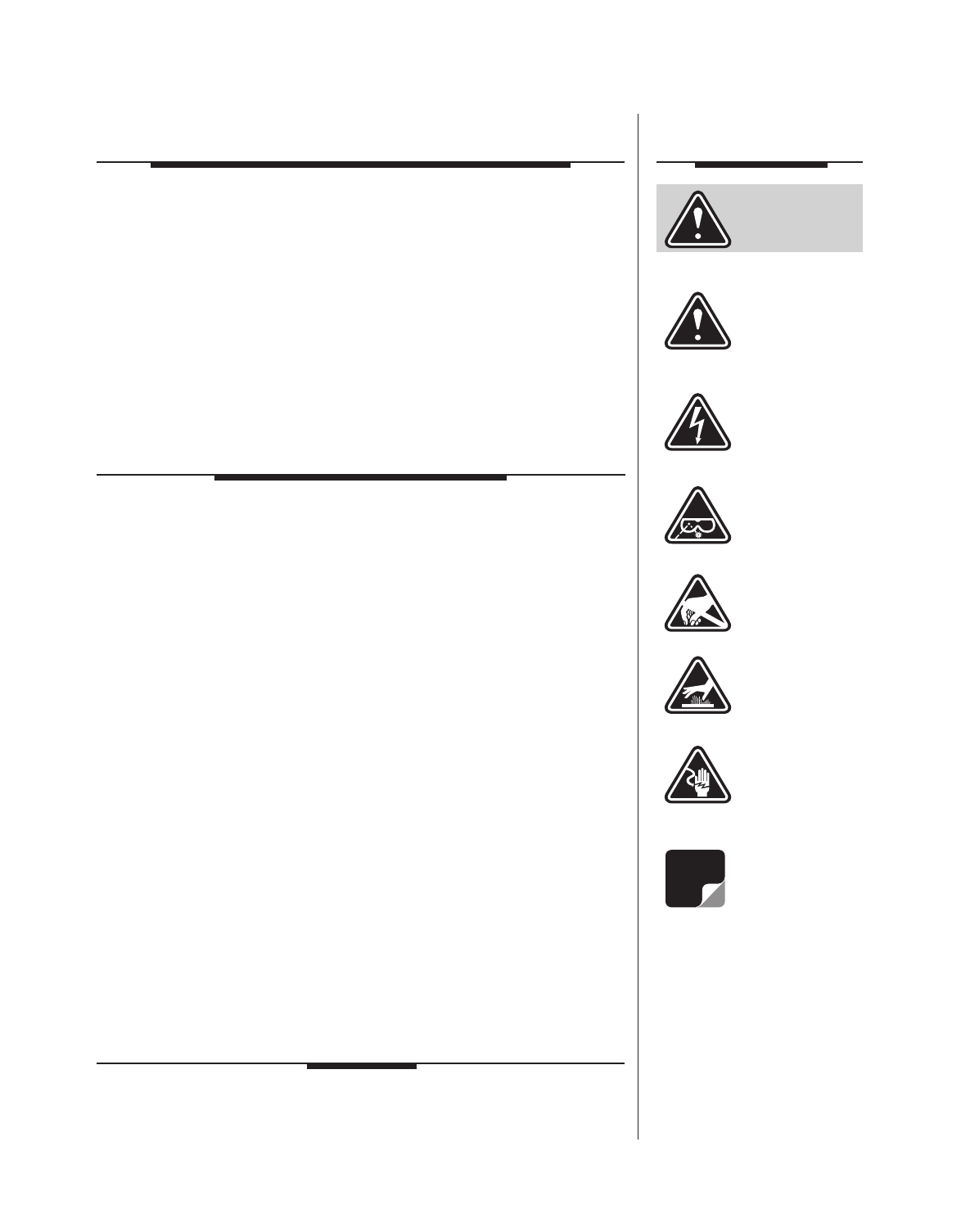
Symbols
Commonly Used
CAUTION or
ATTENTION
High Voltage
Use Safety
Glasses
ESD
Electrostatic
Discharge
Hot Surface
Electrical Shock
Hazard
Important
Information
61-68-50 UserMan page 3 of 25
To satisfy FCC RF exposure requirements for transmitting
devices, a separation distance of 87 Centimeters or more
should be maintained between the UPLINK antenna of this
device and persons during device operation. To satisfy FCC
RF exposure requirements for transmitting devices, a sepa-
ration distance of 30 Centimeters or more should be main-
tained between the DOWNLINK antenna of this device and
persons during device operation. To ensure compliance,
operations at closer than these distances is not recom-
mended.
The antenna used for this transmitter must not be co-located
in conjunction with any other antenna or transmitter.
WARNING
For Class A Unintentional Radiators
This equipment has been tested and found to comply with the limits for a Class A digital device, pursuant to
part 15 of the FCC rules. These limits are designed to provide reasonable protection against harmful inter-
ference when the equipment is operated in a commercial environment. This equipment generates, uses,
and can radiate radio frequency energy and, if not installed and used in accordance with the instruction
manual, may cause harmful interference to radio communications. Operation of this equipment in a resi-
dential area is likely to cause harmful interference in which case the user will be required to correct the
interference at his own expense.
Changes or modifications not expressly approved by TX
RX System Inc. could void the user’s authority to operate
the equipment.
WARNING
This device complies with Part 15 of the FCC Rules. Operation is subject to the
following two conditions: (1) this device may not cause harmful interference and
(2) this device must accept any interference received, including interference
that may cause undesired operation.
61-68-50 UserMan page 4 of 25
Antenna System Installation
The antenna or signal distribution system consists of two branches. An uplink
branch typically uses an outdoor mounted, unidirectional gain antenna such
as a yagi and a downlink signal radiating system consisting of a network of
zero-gain whip antennas or lengths of radiating cable usually mounted inside
of the structure.
Even though the antenna system may not be supplied or installed by TX RX
Systems. The following points need to be observed because both the safety
of the user and proper system performance depend on them.
1) Antenna system installation should only be performed by qualified techni-
cal personnel.
2) The following instructions for your safety describe antenna installation
guidelines based on FCC Maximum RF Exposure Compliance require-
ments.
3) The uplink antenna is usually mounted outside and exchanges signals
with the repeater base station or donor site. It is typically mounted perma-
nently-attached to the building wall or roof. The gain of this antenna should
NOT exceed 10 dB. Only qualified personnel should have access to the
antenna and under normal operating conditions, no one should be able to
touch or approach it within 87 Centimeters (35 inches).
4) The downlink or in-building signal distribution system is connected to the
downlink booster port using coaxial cable. The distribution system may
use radiating coaxial cable or a network 1/4 wave whip antennas whose
gain does not exceed 0 dB for any radiator. These antennas should be
installed so that the user cannot approach any closer than 30 Centimeters
(12 inches) from the antenna.

61-68-50 UserMan page 5 o
f
25
Manual 7-9386-1 09/30/04
Table of Contents
Table of Contents
General Description .............................................................................................. 1
Unpacking ....................................................................................................... 1
Installation ....................................................................................................... 1
Location ....................................................................................................... 1
Mounting ....................................................................................................... 3
Connections ....................................................................................................... 5
AC Line ....................................................................................................... 5
Backup DC Power.................................................................................................. 5
Alarm Terminals (Form-C Contacts) ...................................................................... 5
RF Connections..................................................................................................... 6
Pre-RF Connection Tests ......................................................................................6
Test Equipment ......................................................................................................6
Antenna Isolation ................................................................................................... 6
Procedure for Measuring Antenna Isolation .......................................................... 6
Increase isolation or decrease gain?..................................................................... 7
Normal Operation .................................................................................................. 7
LED Status Indicators............................................................................................8
Front Panel LED’s ................................................................................................ 8
Module LED’s ......................................................................................................8
OLC Light Bars .................................................................................................... 8
Front Panel Controls & the LCD Display................................................................ 8
LCD Screen ....................................................................................................... 10
Configuration Settings ........................................................................................... 10
Restore Orig Configuration.................................................................................10
Calibrate Currents .............................................................................................. 10
Set Gain ....................................................................................................... 10
Set Output Level ................................................................................................. 10
Change Gain Configuration ................................................................................10
Detailed Status Screens ........................................................................................ 11
Amplifiers ....................................................................................................... 11
Power Supply......................................................................................................11
OLC ....................................................................................................... 11
OLC Datalog.......................................................................................................11
Alarms ....................................................................................................... 11
LED Indicators .......................................................................................................12
Form-C contacts ....................................................................................................12
Performance Survey.............................................................................................. 12
Maintenance and Repair ....................................................................................... 13
Power Amplifier Replacement................................................................................14
Module Replacement............................................................................................. 15
Display/User Interface Replacement ..................................................................... 16
Power Supply Replacement...................................................................................17
Duplexer / Filter Replacement ............................................................................... 17
Card Cage Replacement ....................................................................................... 17
Recommended Spares.......................................................................................... 17

61-68-50 UserMan page 6 o
f
25
Manual 7-9386-1 09/30/04
Table of Contents
Figures and Tables
Figure 1 Cabinet mounting hole layout 3
Figure 2 Front internal cabinet view 4
Figure 3 AC power entry 5
Figure 4 Measuring antenna isolation 7
Figure 5 Boot-up display 7
Figure 6 Operational status display 8
Figure 7 Menu System 9
Figure 8 Measuring Booster Gain 12
Figure 9 Performance Survey 13
Figure 10 Removing the Power Amplifier (1 of 3) 14
Figure 11 Removing the Power Amplifier (2 of 3) 14
Figure 12 Removing the Power Amplifier (3 of 3) 15
Figure 13 Disconnecting Display/User Interface 16
Table 1 Model Number Designations 1
Table 2 Product Family 2
Specifications 18
Celsius to Fahrenheit Conversions 19
Manual 7-9386-1 Page 7TX RX Systems Inc. 09/30/04
61-68-50 UserMan page 7 of 25
GENERAL DESCRIPTION
Signal boosters extend radio coverage into areas
where abrupt propagation losses prevent reliable
communication. No frequency translation (conver-
sion) occurs with this device. The UHF version of
Signal Booster II (SB II) is a broadband, bi-direc-
tional signal booster available in a variety of config-
urations as shown in Table 1. The product part
number is used to describe each configuration
available. The UHF version of SB II is available in
the 450 to 512 MHz frequency band. Each of the
three UHF sub-band types are identical except for
differences in the input/output filtering used in the
unit. This manual details the installation and opera-
tion of the 61-68-50 family of boosters which
includes all three sub-bands within the UHF fre-
quency range. The complete product family for the
61-68-50 boosters are listed in Table 2.
The system can be ordered in one of three maxi-
mum gain configurations including Full Gain (+80
dB gain max), Medium Gain (+60 dB gain max),
and Low Gain (+45 dB max gain). The maximum
gain of the system is determined by the exact type
of cards plugged into the low and mid level slots as
shown in the block diagrams at the back of this
manual. The maximum gain of the uplink or down-
link branch is adjustable and can be setup inde-
pendently. In addition, the gain of each branch can
be reduced up to 30 dB in 0.5 dB increments via
software interface.
Three cabinet styles are available. The G1 suffix
denotes a NEMA-4 style cabinet which is suitable
for indoor or outdoor use. The G2 suffix denotes a
stainless steel NEMA-4X style cabinet suitable for
corrosive environments such as salt air and the RM
suffix a rack mount version which is intended for
indoor mounting only.
UNPACKING
It is important to report any visible damage to the
carrier immediately. It is the customer's responsibil-
ity to file damage claims with the carrier within a
short period of time after delivery (1 to 5 days).
Care should be taken when removing the unit from
the packing box to avoid damage to external heat-
sink fins. Use caution because the heatsink fins
can have somewhat sharp corners. Signal Booster
II (SB II) weighs about 100 lbs. so use enough peo-
ple when lifting the unit.
INSTALLATION
The following sections discuss general consider-
ations for installing the booster. All work should be
performed by qualified personal in accordance with
local codes.
Location
The layout of the signal distribution system will be
the prime factor in determining the mounting loca-
tion of Signal Booster II. However, safety and ser-
viceability are also key considerations. The unit
should be located where it cannot be tampered
with by the general public, yet is easily accessible
to service personnel. Also consider the weight of
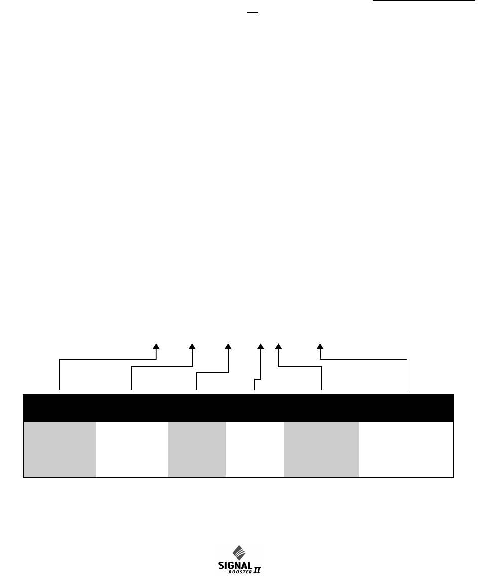
61 - 70 - 50 - A2.0 - G1 (Example)
TYPE SUB-BAND FAMILY COARSE
GAIN
BANDWIDTH ENCLOSURE
TYPE
61 = 2 Way 70 =
71 =
72 =
450 - 470
470 - 490
488 - 512
50 = Signal
Booster
II
A = 80 dB 0.5 =
2.0 =
500 KHz
2.0 MHz
G1 =
G2 =
RM =
Painted, Nema4
Stainless, Nema4X
Rack Mount
Note: Factory preset to 50 dB. Please measure antenna isolation before resetting.
*
*
Table 1 : Part number designations for 61-68-50.
GAI
Manual 7-9386-1 Page 8TX RX Systems Inc. 09/30/04
61-68-50 UserMan page 8 of 25
Part Gain
(dB)
Freq
Range
(MHz)
Band
Width Enclosure
61-70-50-A2.0-G1 80 450-470 2.0MHz NEMA 4
61-71-50-A0.5-G1 80 470-490 500KHz NEMA 4
61-72-50-A0.5-G1 80 488-512 500KHz NEMA 4
Table 2 : SB II model 61-68--50 product family.