Blue Tower Communications TRANSPONDITV9 AMR TRANSMITTER User Manual 72006002 IM 0A
Blue Tower Communications Ltd AMR TRANSMITTER 72006002 IM 0A
UserManual.wiki
>
Blue Tower Communications
>
TRANSPONDITV9 User Manual
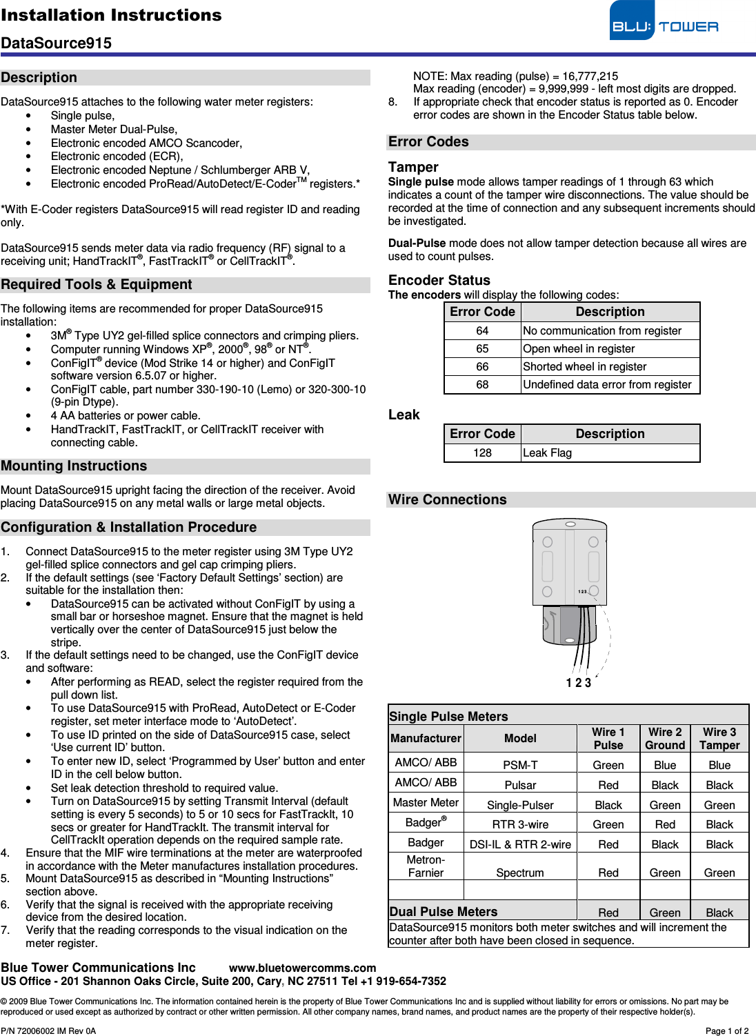
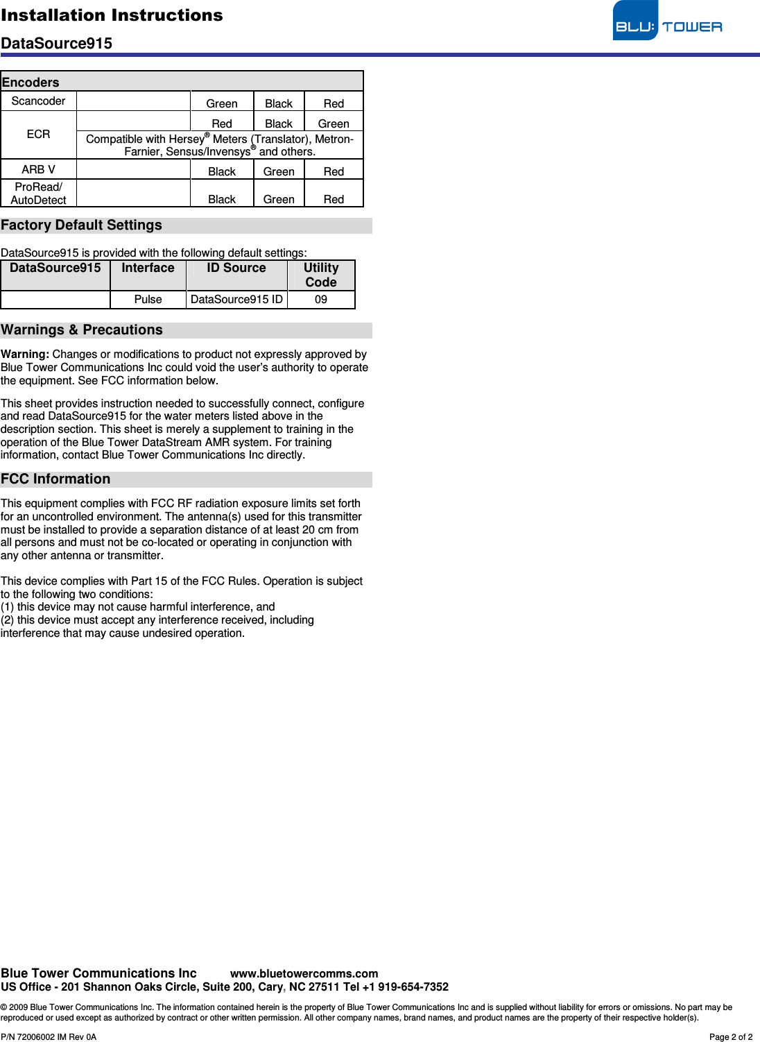
USER MANUAL
Navigation menu
Upload a User Manual
Namespaces
Wiki Guide
HTML
PDF
Info
Views
User Manual
Discussion / Help
Navigation