Blue Tower Communications TRANSPONDITV9 AMR TRANSMITTER User Manual 72006002 IM 0A
Blue Tower Communications Ltd AMR TRANSMITTER 72006002 IM 0A
USER MANUAL
Installation Instructions
DataSource915
Blue Tower Communications Inc
www.bluetowercomms.com
US Office - 201 Shannon Oaks Circle, Suite 200, Cary, NC 27511 Tel +1 919-654-7352
© 2009 Blue Tower Communications Inc. The information contained herein is the property of Blue Tower Communications Inc and is supplied without liability for errors or omissions. No part may be
reproduced or used except as authorized by contract or other written permission. All other company names, brand names, and product names are the property of their respective holder(s).
P/N 72006002 IM Rev 0A Page 1 of 2
Description
DataSource915 attaches to the following water meter registers:
• Single pulse,
• Master Meter Dual-Pulse,
• Electronic encoded AMCO Scancoder,
• Electronic encoded (ECR),
• Electronic encoded Neptune / Schlumberger ARB V,
• Electronic encoded ProRead/AutoDetect/E-Coder
TM
registers.*
*With E-Coder registers DataSource915 will read register ID and reading
only.
DataSource915 sends meter data via radio frequency (RF) signal to a
receiving unit; HandTrackIT
®
, FastTrackIT
®
or CellTrackIT
®
.
Required Tools & Equipment
The following items are recommended for proper DataSource915
installation:
• 3M
®
Type UY2 gel-filled splice connectors and crimping pliers.
• Computer running Windows XP
®
, 2000
®
, 98
®
or NT
®
.
• ConFigIT
®
device (Mod Strike 14 or higher) and ConFigIT
software version 6.5.07 or higher.
• ConFigIT cable, part number 330-190-10 (Lemo) or 320-300-10
(9-pin Dtype).
• 4 AA batteries or power cable.
• HandTrackIT, FastTrackIT, or CellTrackIT receiver with
connecting cable.
Mounting Instructions
Mount DataSource915 upright facing the direction of the receiver. Avoid
placing DataSource915 on any metal walls or large metal objects.
Configuration & Installation Procedure
1. Connect DataSource915 to the meter register using 3M Type UY2
gel-filled splice connectors and gel cap crimping pliers.
2. If the default settings (see ‘Factory Default Settings’ section) are
suitable for the installation then:
• DataSource915 can be activated without ConFigIT by using a
small bar or horseshoe magnet. Ensure that the magnet is held
vertically over the center of DataSource915 just below the
stripe.
3. If the default settings need to be changed, use the ConFigIT device
and software:
• After performing as READ, select the register required from the
pull down list.
• To use DataSource915 with ProRead, AutoDetect or E-Coder
register, set meter interface mode to ‘AutoDetect’.
• To use ID printed on the side of DataSource915 case, select
‘Use current ID’ button.
• To enter new ID, select ‘Programmed by User’ button and enter
ID in the cell below button.
• Set leak detection threshold to required value.
• Turn on DataSource915 by setting Transmit Interval (default
setting is every 5 seconds) to 5 or 10 secs for FastTrackIt, 10
secs or greater for HandTrackIt. The transmit interval for
CellTrackIt operation depends on the required sample rate.
4. Ensure that the MIF wire terminations at the meter are waterproofed
in accordance with the Meter manufactures installation procedures.
5. Mount DataSource915 as described in “Mounting Instructions”
section above.
6. Verify that the signal is received with the appropriate receiving
device from the desired location.
7. Verify that the reading corresponds to the visual indication on the
meter register.
NOTE: Max reading (pulse) = 16,777,215
Max reading (encoder) = 9,999,999 - left most digits are dropped.
8. If appropriate check that encoder status is reported as 0. Encoder
error codes are shown in the Encoder Status table below.
Error Codes
Tamper
Single pulse mode allows tamper readings of 1 through 63 which
indicates a count of the tamper wire disconnections. The value should be
recorded at the time of connection and any subsequent increments should
be investigated.
Dual-Pulse mode does not allow tamper detection because all wires are
used to count pulses.
Encoder Status
The encoders will display the following codes:
Error Code
Description
64 No communication from register
65 Open wheel in register
66 Shorted wheel in register
68 Undefined data error from register
Leak
Error Code
Description
128 Leak Flag
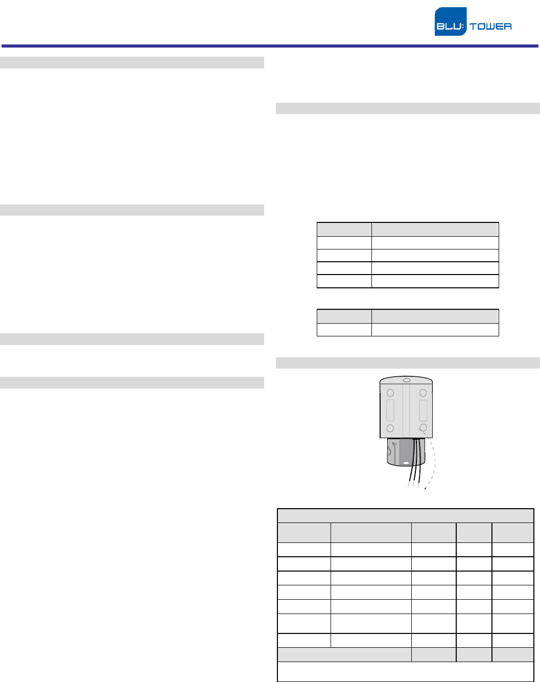
Wire Connections
1 2 3
1 2 3
Single Pulse Meters
Manufacturer
Model Wire 1
Pulse
Wire 2
Ground
Wire 3
Tamper
AMCO/ ABB PSM-T Green Blue Blue
AMCO/ ABB Pulsar Red Black Black
Master Meter
Single-Pulser Black Green Green
Badger
®
RTR 3-wire Green Red Black
Badger DSI-IL & RTR 2-wire
Red Black Black
Metron-
Farnier Spectrum Red Green Green
Dual Pulse Meters
Red Green Black
DataSource915 monitors both meter switches and will increment the
counter after both have been closed in sequence.
Installation Instructions
DataSource915
Blue Tower Communications Inc
www.bluetowercomms.com
US Office - 201 Shannon Oaks Circle, Suite 200, Cary, NC 27511 Tel +1 919-654-7352
© 2009 Blue Tower Communications Inc. The information contained herein is the property of Blue Tower Communications Inc and is supplied without liability for errors or omissions. No part may be
reproduced or used except as authorized by contract or other written permission. All other company names, brand names, and product names are the property of their respective holder(s).
P/N 72006002 IM Rev 0A Page 2 of 2
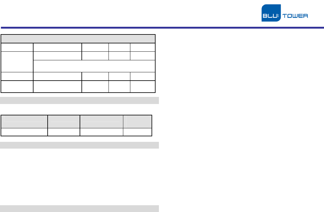
Encoders
Scancoder Green Black Red
Red Black Green
ECR Compatible with Hersey
®
Meters (Translator), Metron-
Farnier, Sensus/Invensys
®
and others.
ARB V Black Green Red
ProRead/
AutoDetect Black Green Red
Factory Default Settings
DataSource915 is provided with the following default settings:
DataSource915 Interface ID Source Utility
Code
Pulse DataSource915 ID
09
Warnings & Precautions
Warning: Changes or modifications to product not expressly approved by
Blue Tower Communications Inc could void the user’s authority to operate
the equipment. See FCC information below.
This sheet provides instruction needed to successfully connect, configure
and read DataSource915 for the water meters listed above in the
description section. This sheet is merely a supplement to training in the
operation of the Blue Tower DataStream AMR system. For training
information, contact Blue Tower Communications Inc directly.
FCC Information
This equipment complies with FCC RF radiation exposure limits set forth
for an uncontrolled environment. The antenna(s) used for this transmitter
must be installed to provide a separation distance of at least 20 cm from
all persons and must not be co-located or operating in conjunction with
any other antenna or transmitter.
This device complies with Part 15 of the FCC Rules. Operation is subject
to the following two conditions:
(1) this device may not cause harmful interference, and
(2) this device must accept any interference received, including
interference that may cause undesired operation.