Bosch Connected Devices and Solutions XDK110 Development Kit User Manual XDK110 2014 12 19 indd
Bosch Connected Devices and Solutions GmbH Development Kit XDK110 2014 12 19 indd
UserManual.wiki
>
Bosch Connected Devices and Solutions
>
XDK110 User Manual
>
UserManual.pdf
Contents
1.
UserManual.pdf
2.
UserManual_Safety.pdf
UserManual.pdf
Navigation menu
Upload a User Manual
Namespaces
Wiki Guide
HTML
PDF
Info
Views
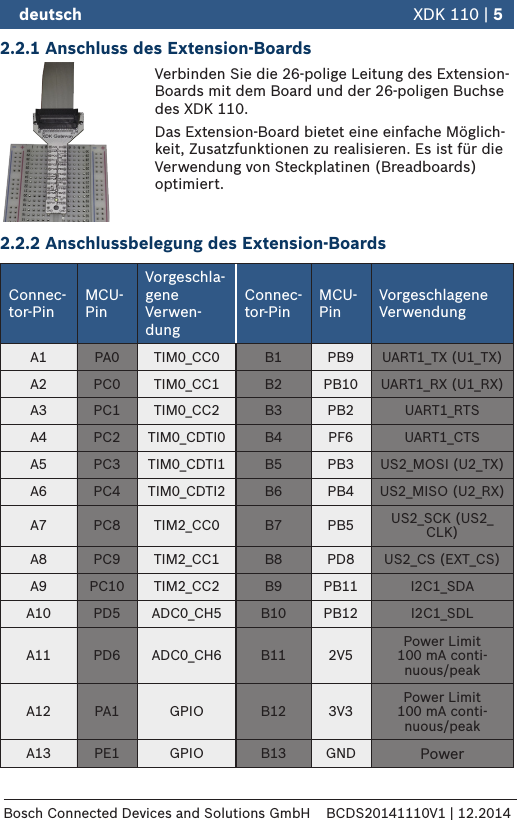
User Manual
Discussion / Help
Navigation