Bosch Connected Devices and Solutions XDK110 Development Kit User Manual XDK110 2014 12 19 indd
Bosch Connected Devices and Solutions GmbH Development Kit XDK110 2014 12 19 indd
Contents
- 1. UserManual.pdf
- 2. UserManual_Safety.pdf
UserManual.pdf

XDK 110 Cross Domain Development Kit
Bosch Connected Devices and
Solutions GmbH
Postfach 13 42
72703 Reutlingen
Germany
Telephone +49 711 811-0
Fax +49 711 35 1084
www.bosch-connectivity.com
Printed in Germany
100 % chlorine free paper
de Bedienungsanleitung
en Operating Instructions

1 Überblick
1. 1 Einsatzzweck des XDK 110
Das XDK 110 Cross Domain Development Kit ist eine Entwicklungsplatt-
form für Anwendungen des „Internets der Dinge“ (IoT) für Windows7
oder höher.
1.2 Lieferumfang
• XDK 110 Development Kit inkl. Lithium-Ionen Akku
• Extension-Board mit Leitung 10 cm, 26-polig
• Micro USB 2.0 Anschlussleitung
• Halteplatte und Schrauben
1.3 Sensorik
• BMA280 Beschleunigung
• BMG160 Drehrate
• BMM150 Magnetfeld
• BMI160 Beschleunigung/Drehrate
• BME280 Feuchtigkeit/Luftdruck/Temperatur
• AKU340 Umgebungslautstärke
• MAX44009 Umgebungslicht
1.4 Speicher
• Micro-SD-Kartenslot
1.5 Kommunikation
• Kabelgebunden: USB 2.0
• Kabellos: Bluetooth; Wireless LAN
• LED: 1x grün, 1x gelb, 1x orange, 1x rot
Im Anwendungsmodus können Sie die LED Rot, Orange und Gelb
ansteuern.
2 | XDK 110 deutsch
BCDS20141110V1 | 12.2014 Bosch Connected Devices and Solutions GmbH
1. 6 Technische Daten
Bezeichnung Wert
Temperaturbereich 0 – 60 °C
Luftfeuchte bis 31 °C max. 80 %; linear fallend
auf 50 % bei 40 °C
Schutzklasse IP 30 nach IEC 60529
Brandschutzklasse HB (IEC 60695-11-10/-20; CSA C 22.2)
Betriebsspannung 5 V Gleichspannung
Stromstärke 500 mA maximal
Kommunikation (kabelgebunden) USB
Wireless LAN IEEE 802.11 b/g/n
Bluetooth 4.0 IEEE 802.15.1
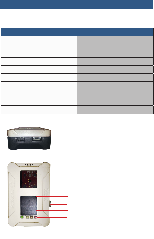
1.7 Anschlüsse, Buttons und LED
deutsch XDK 110 | 3
Bosch Connected Devices and Solutions GmbH BCDS20141110V1 | 12.2014
USB
Power
JTAG
LED
Extension Board
Button 1
Button 2

2 Inbetriebnahme und Software
Die Software für das XDK 110 ist online verfügbar. Rufen Sie die Seite
http://www.xdk.bosch-connectivity.com auf. Unter Downloads finden Sie
die aktuelle Version der Softwarepakete sowie Anwendungsbeispiele
(Demos).
2.1 Softwaredownload und Installation
Laden Sie das Softwarepaket „XDK Workbench“ von der Herstellerweb-
site http://www.xdk.bosch-connectivity.com herunter und starten Sie den
Installer. Das Softwarepaket enthält alle notwendigen Komponenten
sowie Beispiele, Demos und die Toolbox (s. 2.3 Erste Schritte).
2.2 Anschluss des XDK 110
Verbinden Sie das mitgelieferte USB-Kabel mit der USB-Buchse des PC
und der Micro-USB-Buchse des XDK 110.
Folgende Zustände zeigt das XDK 110 mithilfe der LED:
Nach dem ersten Einschalten wird eine Lauflicht-Demo angezeigt.
LED Grün:
Die grüne LED dient der Lade-Erkennung und kann nicht über Software
gesteuert werden.
Dauerlicht: Ladend/Temperatursicherheitsschalter ausgelöst
Blinkend: Sicherheitszeitschalter ausgelöst
Aus: Laden beendet/Akku nicht vorhanden/Fehler in der Span-
nungsversorgung/Ladeschaltkreis deaktiviert
Wenn das Gerät im Bootloadermodus ist, sind folgende LEDs aktiv:
LED Gelb:
Dauerlicht: Bootloadermodus aktiv und USB verbunden; Treiber geladen
LED Rot:
Dauerlicht:
Bootloadermodus aktiv
Blinken 5x:
Keine gültige Anwendung erkannt, XDK bleibt im Bootloadermodus
4 | XDK 110 deutsch
BCDS20141110V1 | 12.2014 Bosch Connected Devices and Solutions GmbH
Funktionseinschränkungen
Das Gerät kann beeinträchtigt oder beschädigt werden, wenn die Span-
nungsversorgung nicht korrekt ist.
• Verwenden Sie keine Verbindungsleitungen >┘3 m.
• Verwenden Sie nur zertifizierte USB-Ladegeräte
Hinweis

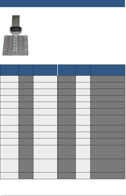
2.2.1 Anschluss des Extension-Boards
Verbinden Sie die 26-polige Leitung des Extension-
Boards mit dem Board und der 26-poligen Buchse
des XDK 110.
Das Extension-Board bietet eine einfache Möglich-
keit, Zusatzfunktionen zu realisieren. Es ist für die
Verwendung von Steckplatinen (Breadboards)
optimiert.
2.2.2 Anschlussbelegung des Extension-Boards
Connec-
tor-Pin
MCU-
Pin
Vorgeschla-
gene
Verwen-
dung
Connec-
tor-Pin
MCU-
Pin
Vorgeschlagene
Verwendung
A1 PA0 TIM0_CC0 B1 PB9 UART1_TX (U1_TX)
A2 PC0 TIM0_CC1 B2 PB10 UART1_RX (U1_RX)
A3 PC1 TIM0_CC2 B3 PB2 UART1_RTS
A4 PC2 TIM0_CDTI0 B4 PF6 UART1_CTS
A5 PC3 TIM0_CDTI1 B5 PB3 US2_MOSI (U2_TX)
A6 PC4 TIM0_CDTI2 B6 PB4 US2_MISO (U2_RX)
A7 PC8 TIM2_CC0 B7 PB5 US2_SCK (US2_
CLK)
A8 PC9 TIM2_CC1 B8 PD8 US2_CS (EXT_CS)
A9 PC10 TIM2_CC2 B9 PB11 I2C1_SDA
A10 PD5 ADC0_CH5 B10 PB12 I2C1_SDL
A11 PD6 ADC0_CH6 B11 2V5 Power Limit
100mA conti-
nuous/peak
A12 PA1 GPIO B12 3V3 Power Limit
100mA conti-
nuous/peak
A13 PE1 GPIO B13 GND Power
deutsch XDK 110 | 5
Bosch Connected Devices and Solutions GmbH BCDS20141110V1 | 12.2014

2.3 Erste Schritte
• Starten Sie die Software „XDK Workbench“.
• Der „Welcome“-Bildschirm erscheint.
• Bei angeschlossenem XDK erscheint das XDK-Symbol.
• Erstellen Sie Ihre Applikation.
• Drücken Sie den „Flash“ Button. Ihre Applikation wird auf das XDK
geladen (s. 2.3.1).
• Überprüfen Sie die Ausgaben des XDK mithilfe der Konsole der
„XDK Workbench“
2.3.1 Flashen
Das XDK 110 lässt sich nur im Bootloader programmieren. Drücken Sie
hierzu den „Flash“-Button. Die Software bringt das XDK 110 in den
Bootloadermodus, flasht das Programm und bootet das XDK neu.
Falls die Software den Bootloadermodus nicht herstellt, kann dies
manuell erfolgen:
• Schalten sie das XDK aus
• Drücken Sie den Button 1
• Halten Sie Button 1 gedrückt und schalten Sie das XDK wieder an.
Die rote LED leuchtet auf. Bei bestehender USB-Verbindung leuchtet
auch die gelbe LED. Drücken Sie den „Flash“-Button.
2.3.2 Demos
Im Softwarepaket sind drei Demos enthalten:
• Data Logger: Speichert Sensordaten auf eine Micro-SD Karte
• Virtual XDK: Rendert auf einem Tablet ein via Bluetooth verbundenes
XDK, das sich analog zum realen XDK bewegt
• Sensor Monitor: Darstellung der Rohdaten der Sensoren in 2D-Dar-
stellung (Samples über Zeit)
6 | XDK 110 deutsch
BCDS20141110V1 | 12.2014 Bosch Connected Devices and Solutions GmbH

2.3.3 Toolbox
Die Toolbox enthält verschiedene Funktionsblöcke und Algorithmen, wie
Filter, FFT (Fast Fourier Transform), etc. Mithilfe der Toolbox kann z. B.
über die Rohdaten des Drehratensensors und des Beschleunigungssen-
sors die Lage im Raum abgeleitet werden.
2.3.4 API-Dokumentation
Die API-Dokumentation kann über die Hilfefunktion der „XDK Workbench“
aufgerufen werden.
2.3.5 Community
Besuchen Sie http://www.xdk.bosch-connectivity.com.Im Forum können
Sie Updates und Programmierbeispiele finden, technischen Support
erhalten und sich mit anderen XDK-Nutzern austauschen.
2.3.6. Zubehör
Ergänzend kann über die Firma Segger (http://www.segger.com) der
J-Link Adapter „J-Link 9-pin Cortex-M Adapter“ bezogen werden. Der
Adapter ermöglicht es, das Programm auf dem XDK110 per JTAG zu
debuggen. Beziehen Sie sich bei Ihrer Bestellung auf das XDK 110 um
den korrekten Adapter zu erhalten.
2.3.7 Weitere Informationen
Das Gerät sollte nicht dauerhaft am Körper getragen werden.
deutsch XDK 110 | 7
Bosch Connected Devices and Solutions GmbH BCDS20141110V1 | 12.2014

1 Overview
1. 1 Intended Use
The XDK 110 Cross-Domain Development Kit is a prototyping platform
for
Internet of Things (IoT) use cases. It works with Windows7 or higher.
1.2 Included in Delivery
• XDK 110 Development Kit with Lithium Ion Battery
• Extension board with cable; 10 cm, 26 pin
• Micro USB 2.0 connector cable
• Mounting plate and screws
1.3 Sensors
• BMA280 Accelerometer
• BMG160 Gyroscope
• BMM150 Magnetometer
• BMI160 Accelerometer/Gyroscope
• BME280 Humidity/Pressure/Temperature
• AKU340 Ambient Noise
• MAX44009 Ambient Light
1.4 Data storage
• Micro-SD card slot
1.5 Communication
• Cable: USB 2.0
• Wireless: Bluetooth; Wireless LAN
• LED: 1x green, 1x yellow, 1x orange, 1x red
The LED Red, Orange and Yellow can be controlled in application mode.
8 | XDK 110 english
BCDS20141110V1 | 12.2014 Bosch Connected Devices and Solutions GmbH

1. 6 Technical Specifications
Name Value
Temperature Range 0 – 60 °C
Humidity up to 31 °C max. 80 %; linear
decrease to 50 % at 40 °C
IP Rating IP 30 (IEC 60529)
Flammability classification HB (IEC 60695-11-10/-20; CSA C 22.2)
Voltage 5 V DC
Charging Current 500 mA maximum
Communication (cable) USB
Wireless LAN IEEE 802.11 b/g/n
Bluetooth 4.0 IEEE 802.15.1
1.7 Connectors, Buttons and LED
english XDK 110 | 9
Bosch Connected Devices and Solutions GmbH BCDS20141110V1 | 12.2014
USB
Power
JTAG
LED
Extension Board
Button 1
Button 2

2 Start-up and Software
The software for the XDK is online available. You can download the
software from http://www.xdk.bosch-connectivity.com. Go to the down-
load section to get the latest software package and demos.
2.1 Download and Installation
Download the software package “XDK Workbench“ from the website
http://www.xdk.bosch-connectivity.com and start the installer. The
software package contains all necessary components. Program examples,
demos and a Toolbox are included (please refer 2.3. “Getting started“).
2.2 Connecting XDK 110
Connect the USB cable that was included in delivery to with the USB
connector of your PC and the Micro-USB Connector of the XDK.
The XDK 110 uses the LED to show the following states:
After XDK 110 has been switched on the first time, a running light demo
will start.
LED Green:
The green LED shows the charging status and cannot be controlled by
software.
Continuous: Charging/Charging suspended by thermal loop.
Flashing: Safety timers expired
Off: Charging done/Recharging after termination/IC disabled
or no valid input power/Battery absent.
The following LED are active if the XDK is in bootloader mode:
LED Yellow:
Continuous:
Bootloader mode active and USB connected; Driver loaded
LED Red:
Continuous: Bootloader mode active
Flashing 5x:No valid application detected; XDK remains in bootloader
mode
10 | XDK 110 english
BCDS20141110V1 | 12.2014 Bosch Connected Devices and Solutions GmbH
Functional Limitations
The device can be impaired or damaged if the power source is inadequate.
• Do not use cables >┘3 m.
• Use only certified USB power adapters
notice
2.2.1 Connecting the Extension Board
Connect the 26-pin cable that was included in
delivery with the extension board to the 26-pin
connector of the XDK 110.
The extension board offers a simple way to imple-
ment additional functions. It is optimized for the use
of breadboards.
2.2.2 Connector Pin Assignment on the Extension Board
Connec-
tor Pin
MCU-
Pin
Suggested
Use
Connec-
tor Pin
MCU-
Pin Suggested Use
A1 PA0 TIM0_CC0 B1 PB9 UART1_TX (U1_TX)
A2 PC0 TIM0_CC1 B2 PB10 UART1_RX (U1_RX)
A3 PC1 TIM0_CC2 B3 PB2 UART1_RTS
A4 PC2 TIM0_CDTI0 B4 PF6 UART1_CTS
A5 PC3 TIM0_CDTI1 B5 PB3 US2_MOSI (U2_TX)
A6 PC4 TIM0_CDTI2 B6 PB4 US2_MISO (U2_RX)
A7 PC8 TIM2_CC0 B7 PB5 US2_SCK (US2_
CLK)
A8 PC9 TIM2_CC1 B8 PD8 US2_CS (EXT_CS)
A9 PC10 TIM2_CC2 B9 PB11 I2C1_SDA
A10 PD5 ADC0_CH5 B10 PB12 I2C1_SDL
A11 PD6 ADC0_CH6 B11 2V5 Power Limit
100mA conti-
nuous/peak
A12 PA1 GPIO B12 3V3 Power Limit
100mA conti-
nuous/peak
A13 PE1 GPIO B13 GND Power
english XDK 110 | 11
Bosch Connected Devices and Solutions GmbH BCDS20141110V1 | 12.2014

2.3 Getting Started
• Start the software “XDK Workbench“.
• The “Welcome“ screen will appear.
• If an XDK is connected, the XDK symbol will appear.
• Create your application.
• Click on the “Flash“ Button. Your application will be transferred to
the XDK.
• Check the output of the XDK by using the console of the
“XDK-Workbench“
2.3.1 Flashing the XDK 110
The XDK 110 can only be programmed while in bootloader mode. To
enter bootloader mode, press the “Flash” button. The software puts the
XDK 110 in bootloader mode, flashes the programm and reboot.
If the software does not put the XDK 110 in bootloader mode, this can
be done manually:
• Switch off the XDK 110.
• Press Button 1.
• Hold down Button 1 and switch the XDK 110 back on.
The red LED will light up. If a USB connection is already established, the
yellow LED will also light up. Press the “Flash” button
2.3.2 Demos
The software package contains three demos:
• Data Logger: Storage of sensor data on a Micro-SD card
• Virtual XDK: Renders an XDK that is connected to a tablet via
Bluetooth. The XDK on the tablet moves analogously to the real XDK.
• Sensor Monitor: Shows a 2-D view of the raw sensor data (samples
over time)
2.3.3 Toolbox
The Toolbox contains various function blocks and und algorithms, like
filters, FFT (Fast Fourier Transform) and more. For example, the toolbox
can help determine the spatial position of the XCK 110 by using the raw
data from the gyroscope and the accelerometer.
12 | XDK 110 english
BCDS20141110V1 | 12.2014 Bosch Connected Devices and Solutions GmbH

2.3.4 API Documentation
The API documentation can be opened using the “Help“ function of the
“XDK-Workbench“.
2.3.5 Community
Visit http://www.xdk.bosch-connectivity.com. Find updates and further
program examples in the forum. You can also communicate with other
XDK users in the forum. Find updates and program examples, get
technical support, and communicate with other XDK users in the forum.
2.3.6 Acessories
Additionally, the J-link adapter “J-Link 9-Pin Cortex-M Adapter” can be
purchased from Segger (http://www.segger.com). The adapter facilitates
using JTAG to debug the program on the XDK 110. While ordering, refer
to XDK 110 to get the right adapter.
2.3.7 Radiofrequency Radiation Exposure and further Informa-
tion
The radiated output power of the device is far below the FCC radio
frequency exposure limits. Nevertheless, the device shall be used in such
a manner that the potential for human contact during normal operation is
minimized.
english XDK 110 | 13
Bosch Connected Devices and Solutions GmbH BCDS20141110V1 | 12.2014
This device complies with Part 15 of the FCC Rules and with Industry
Canada licence-exempt RSS standard(s).
Operation is subject to the following three conditions:
• this device may not cause harmful interference, and
• this device must accept any interference received, including interfe-
rence that may cause undesired operation.
• The minimum distance between body an device should be 20 cm.
Le présent appareil est conforme aux CNR d‘Industrie Canada applicables
aux appareils radio exempts de licence. L‘exploitation est autorisée aux
trois conditions suivantes:
• l‘appareil ne doit pas produire de brouillage, et
• l‘utilisateur de l‘appareil doit accepter tout brouillage radioélectrique
subi, même si le brouillage est susceptible d‘en compromettre le
fonctionnement.
• La distance minimum entre appareil et corps est 20 cm.
notice