Bosch Security Systems ATX-CR-RV Allplex track User Manual ALLPLEX track Coordinator Receiver
Bosch Security Systems, Inc. Allplex track ALLPLEX track Coordinator Receiver
UserManual.wiki
>
Bosch Security Systems
>
ATX-CR-RV User Manual
>
installation manual
Contents
1.
Users Manual
2.
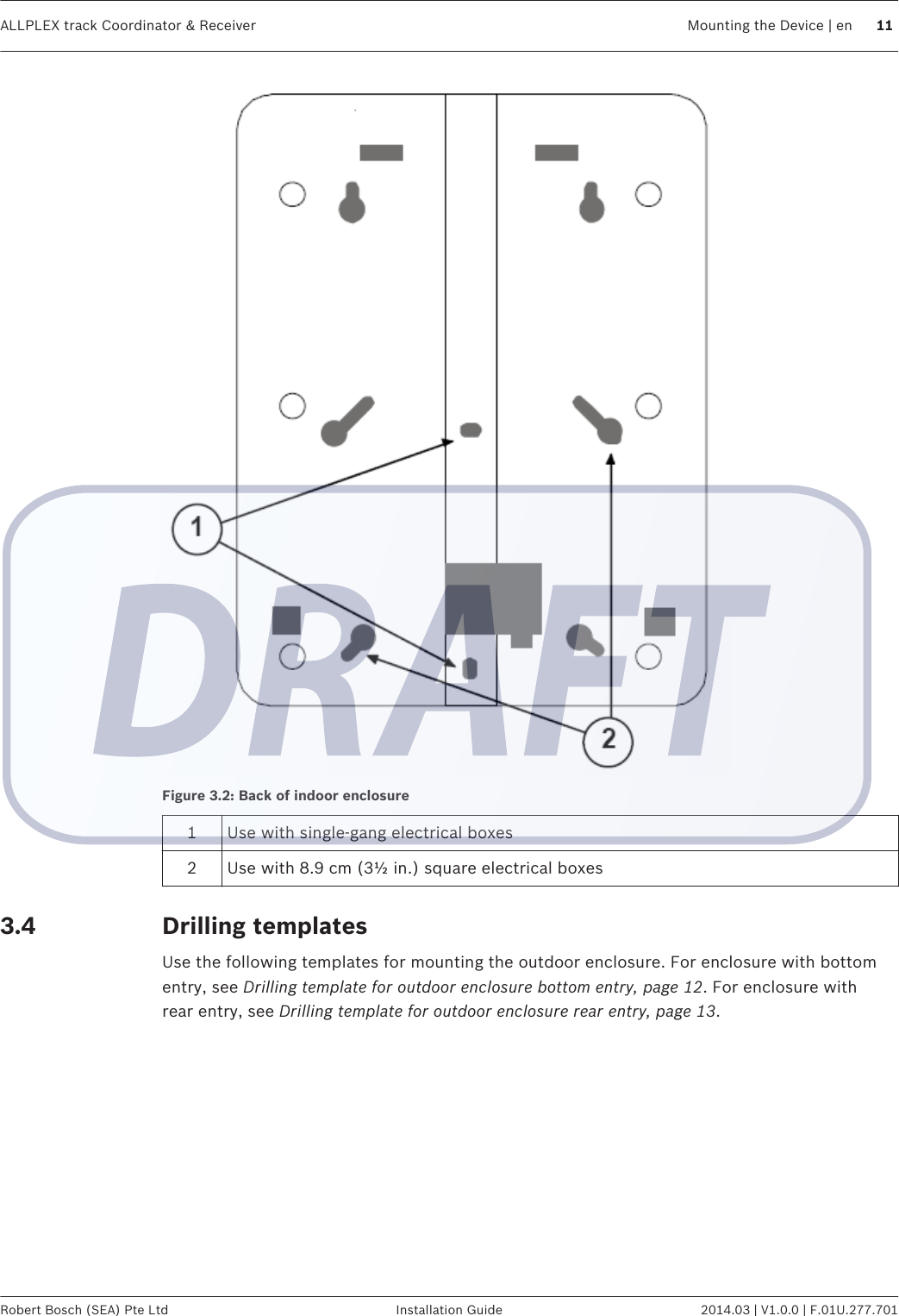
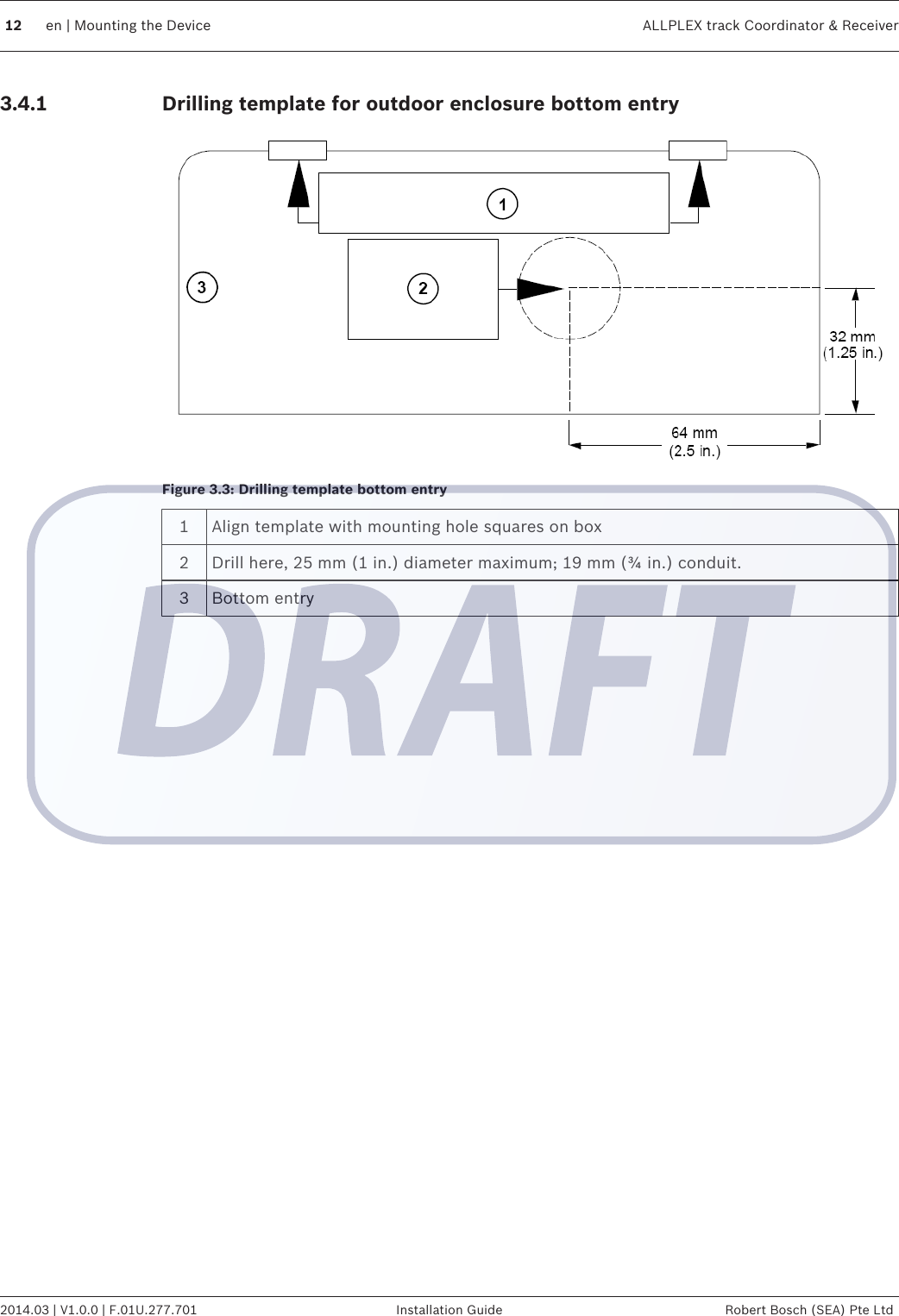
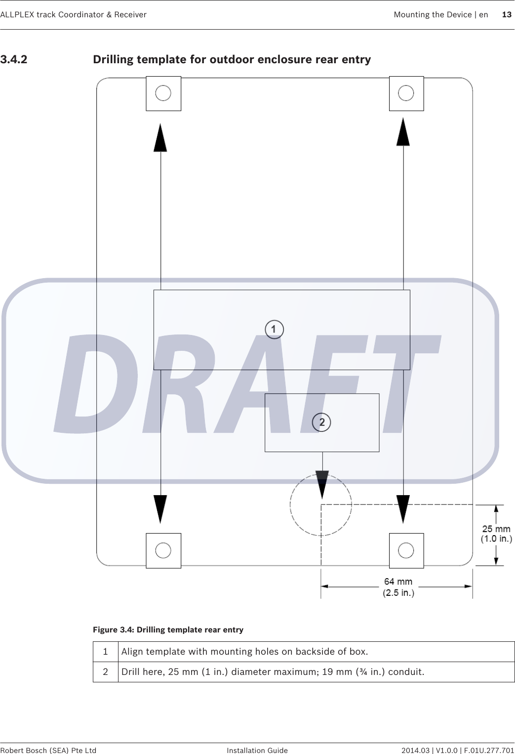
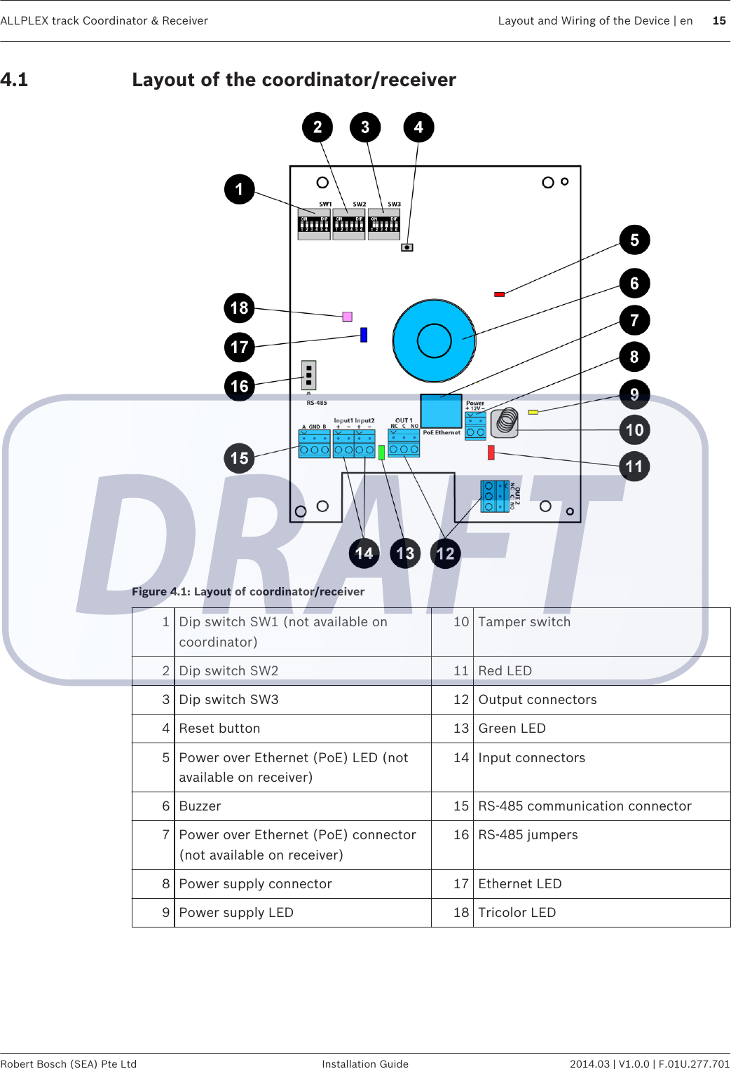
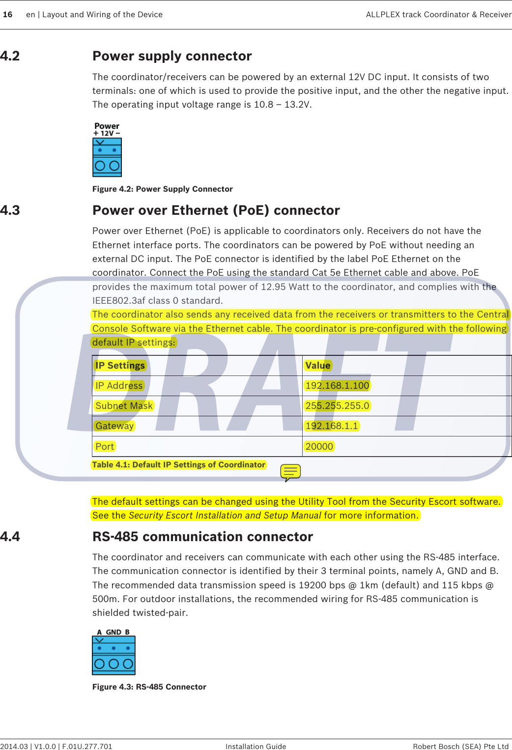
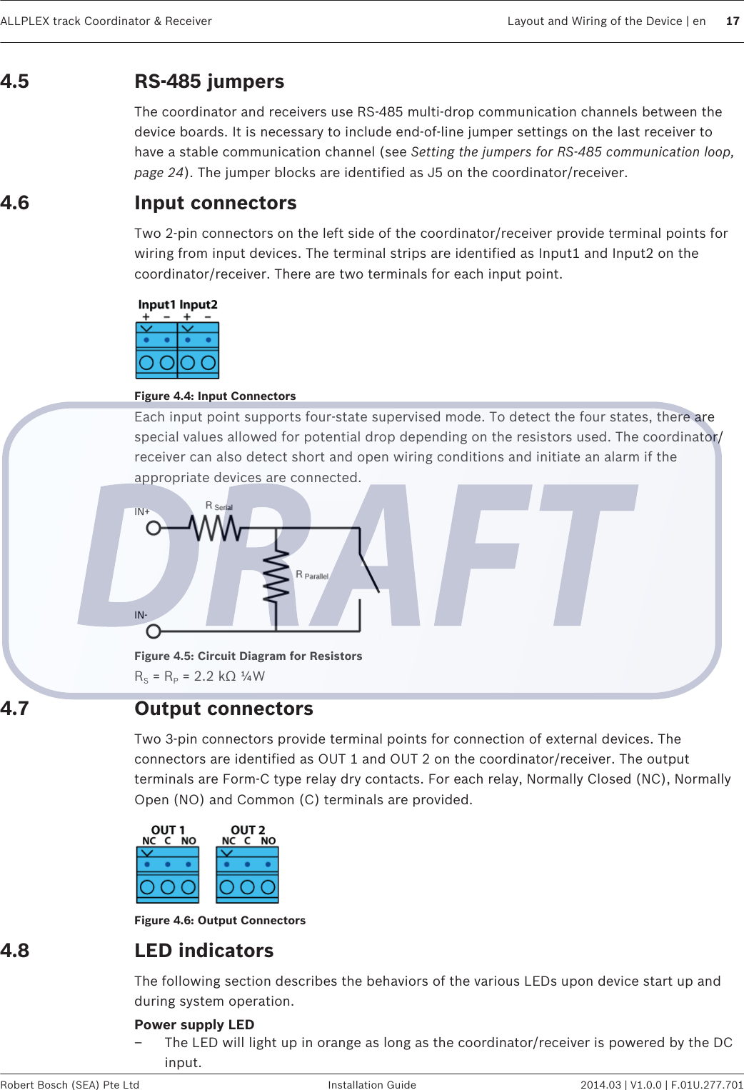
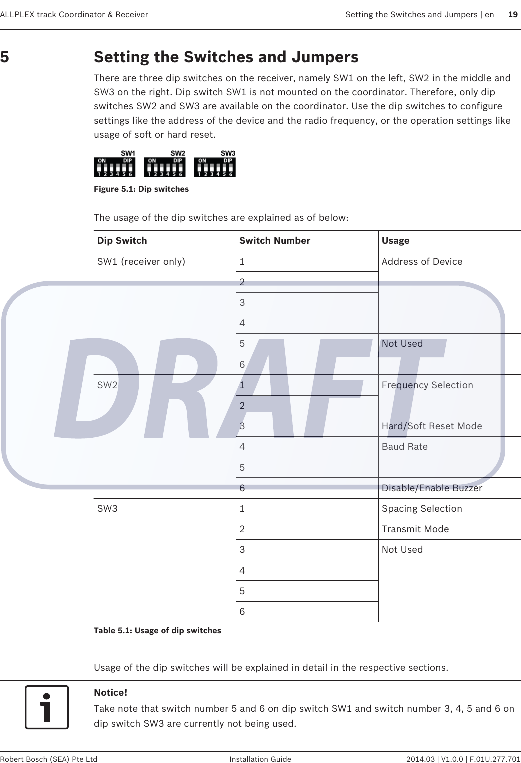
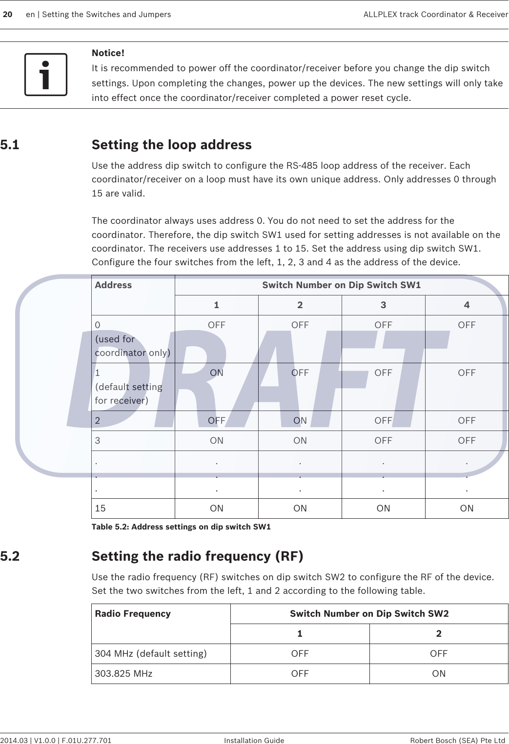
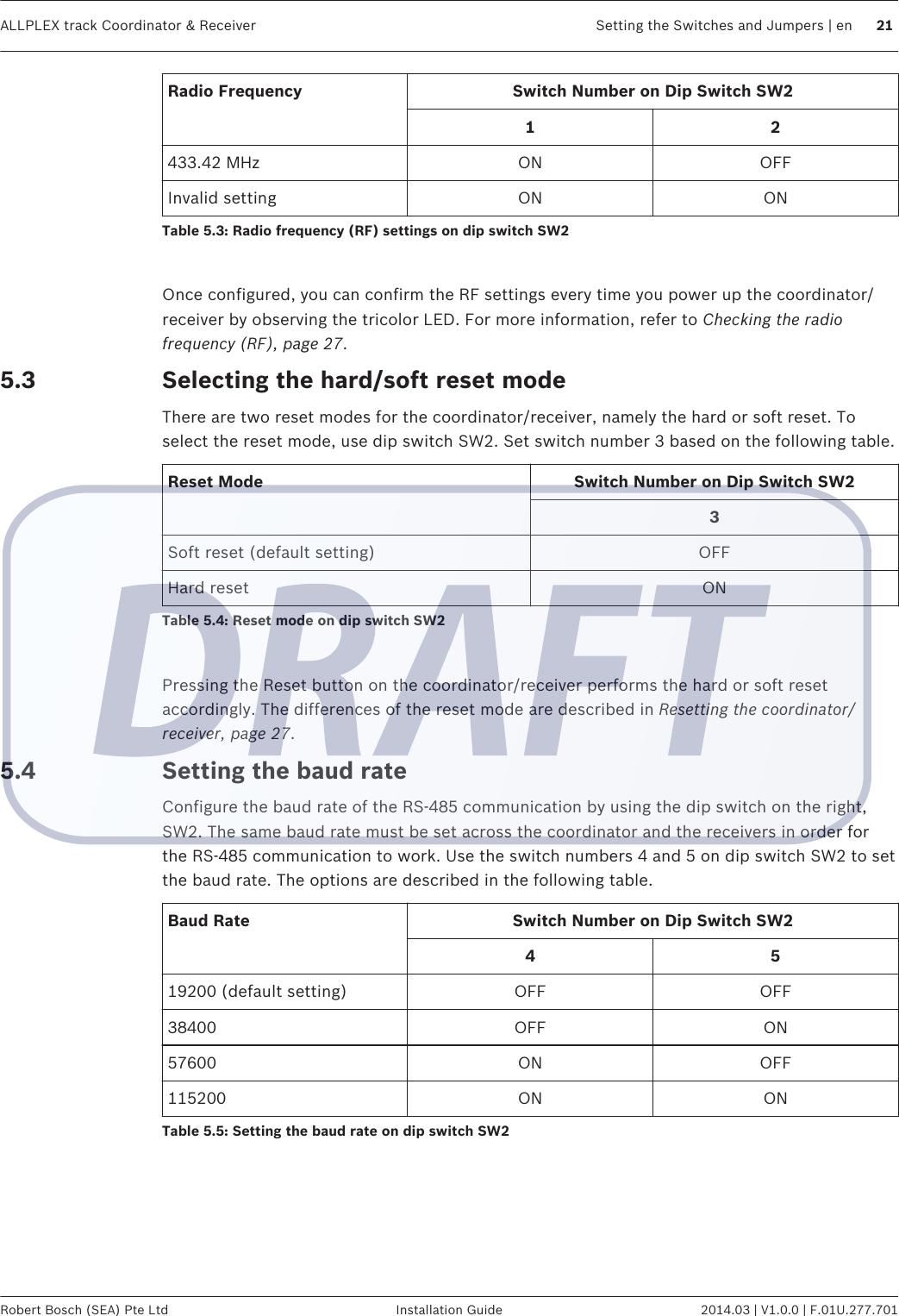
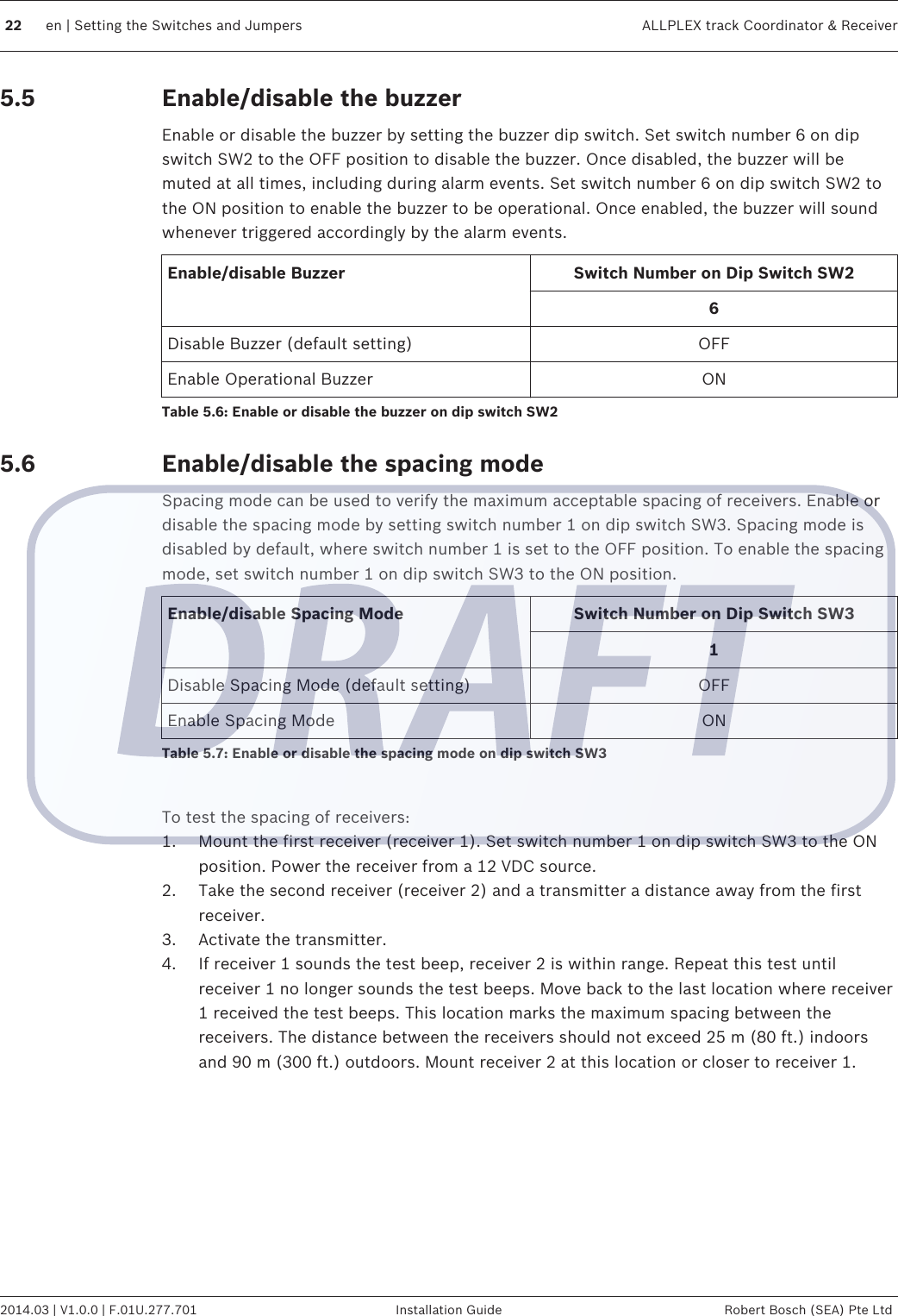
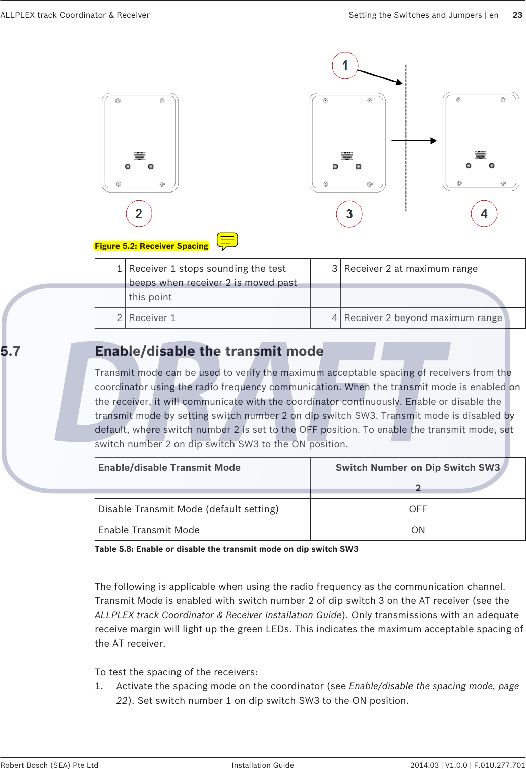
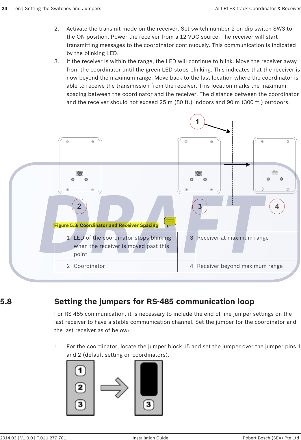
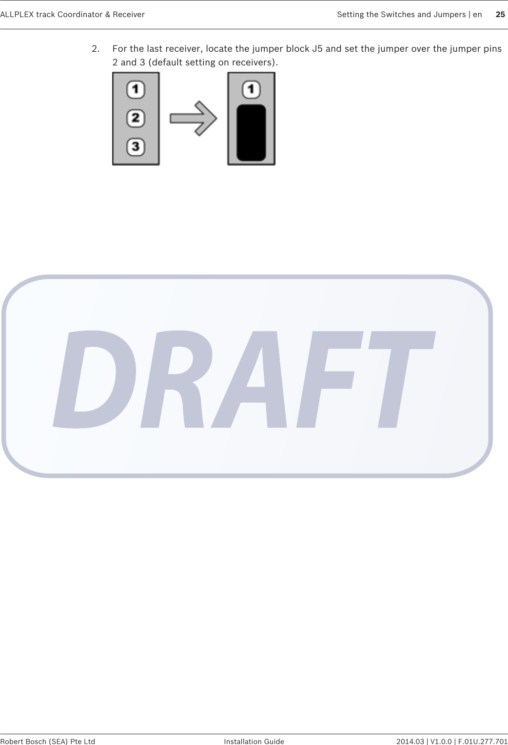
installation manual
installation manual
Navigation menu
Upload a User Manual
Namespaces
Wiki Guide
HTML
PDF
Info
Views
User Manual
Discussion / Help
Navigation