Bosch Security Systems ATX-CR-RV Allplex track User Manual ALLPLEX track Coordinator Receiver
Bosch Security Systems, Inc. Allplex track ALLPLEX track Coordinator Receiver
Contents
- 1. Users Manual
- 2. installation manual
installation manual

ALLPLEX track Coordinator & Receiver
ATX-COR-MT01 & ATX-RCV-MT01
en Installation Guide

Table of contents
1Copyright, Safety and Warranty 5
1.1 Copyright information 5
1.2 Important safety notes 6
1.3 Safety precautions 7
1.4 FCC information 7
2System Overview 8
3Mounting the Device 9
3.1 Indoor installation 9
3.1.1 Spacing 9
3.1.2 Mounting height 9
3.1.3 Multi-floor installations 9
3.2 Outdoor installation 10
3.2.1 Spacing 10
3.2.2 Mounting height 10
3.2.3 Overhangs/eaves 10
3.3 Pre-wired installations 10
3.4 Drilling templates 11
3.4.1 Drilling template for outdoor enclosure bottom entry 12
3.4.2 Drilling template for outdoor enclosure rear entry 13
4Layout and Wiring of the Device 14
4.1 Layout of the coordinator/receiver 15
4.2 Power supply connector 16
4.3 Power over Ethernet (PoE) connector 16
4.4 RS-485 communication connector 16
4.5 RS-485 jumpers 17
4.6 Input connectors 17
4.7 Output connectors 17
4.8 LED indicators 17
4.9 Tamper switch 18
4.10 Reset button 18
5Setting the Switches and Jumpers 19
5.1 Setting the loop address 20
5.2 Setting the radio frequency (RF) 20
5.3 Selecting the hard/soft reset mode 21
5.4 Setting the baud rate 21
5.5 Enable/disable the buzzer 22
5.6 Enable/disable the spacing mode 22
5.7 Enable/disable the transmit mode 23
5.8 Setting the jumpers for RS-485 communication loop 24
6Troubleshooting the Device 26
6.1 Checking the power supply 26
6.2 Checking Power over Ethernet (PoE) 26
6.3 Checking Ethernet network issues 26
6.4 Checking the RS-485 communication 26
6.5 Checking the radio frequency (RF) 27
6.6 Resetting the coordinator/receiver 27
6.7 Upgrading coordinator/receiver firmware 27
ALLPLEX track Coordinator & Receiver Table of Contents | en 3
Robert Bosch (SEA) Pte Ltd Installation Guide 2014.03 | V1.0.0 | F.01U.277.701


Copyright, Safety and Warranty
Copyright information
All rights reserved. No part of this manual may be reproduced, stored in a retrieval system, or
transmitted in any form or by any means, electronic, mechanical, photocopying, recording, or
otherwise, without the prior written permission of BOSCH SECURITY SYSTEMS.
This manual is provided pursuant to a license agreement containing restrictions on their use.
The manual contains valuable trade secrets and proprietary information of BOSCH SECURITY
SYSTEMS and is protected by international copyright law. It may not be copied or distributed
to third parties, or used in any manner not provided for in the said license agreement.
All software is provided "AS IS." The sole obligation of BOSCH SECURITY SYSTEMS shall be to
make available all published modifications that correct program problems are published within
one (1) year from the date of shipment.
The software is intended for use only with the hardware specified in this manual and in the
absence of other software. Concurrent use with other software or with hardware not specified
may cause the program to function improperly or not at all. BOSCH SECURITY SYSTEMS may
not provide support for systems operating under such conditions.
All efforts have been made to ensure the accuracy of the contents of this manual. The above
notwithstanding, BOSCH SECURITY SYSTEMS assume no responsibility for any errors in this
manual or their consequences.
The information on this document is subject to change without notice.
Other product and company names mentioned herein may be the trademarks of their
respective owners.
1
1.1
ALLPLEX track Coordinator & Receiver Copyright, Safety and Warranty | en 5
Robert Bosch (SEA) Pte Ltd Installation Guide 2014.03 | V1.0.0 | F.01U.277.701

Important safety notes
1. Read, Follow, and Retain Instructions – All safety and operating instructions must be
read and followed properly before putting the unit into operation. Retain instructions for
future reference.
2. Consider all Warnings – Adhere to all warnings on the unit and in the operating
instructions.
3. Accessories – Use only accessories recommended by the manufacturer or those sold
with the product. Accessories not recommended by the manufacturer shall not be used,
as they may cause hazards.
4. Installation Precautions – Do not place this unit on an unstable stand, tripod, bracket, or
mount. The unit may fall, causing serious injury to persons and damage to the unit. Mount
the unit according to the manufacturer’s instructions.
5. Service – Do not attempt to service this unit by yourself. Opening or removing covers may
expose you to dangerous voltages or other hazards. Refer all servicing to qualified service
personnel.
6. Damage Requiring Service – Disconnect the unit from the main AC or DC power source
and refer servicing to qualified service personnel under the following conditions:
– When the power supply cord or plug is damaged.
– If liquid has been spilled or an object has fallen into the unit.
– If the unit has been exposed to water and/or inclement weather (rain, snow, etc.).
– If the unit does not operate normally, when following the operating instructions.
Adjust only those controls specified in the operating instructions. Improper
adjustment of other controls may result in damage, and require extensive work by a
qualified technician to restore the unit to normal operation.
– If the unit has been dropped or the cabinet damaged.
– If the unit exhibits a distinct change in performance, this indicates that service is
needed.
7. Replacement Parts – When replacement parts are required, the service technician shall
use replacement parts that are specified by the manufacturer. Unauthorized substitutions
may result in fire, electrical shock or other hazards.
8. Safety Check – Upon completion of service or repair work on the unit, ask the service
technician to perform safety checks to ensure that the unit operates properly.
9. Power Sources – Operate the unit only from the type of power source indicated on the
label. If unsure of the type of power supply to use, contact your dealer.
– For units intended to operate from battery power, refer to the operating instructions.
– For units intended to operate with External Power Supplies, use only the
recommended approved power supplies.
10. Lightning – For added protection during a lightning storm, or when this unit is left
unused for long periods of time, disconnect the unit from power. This will prevent
damage to the unit due to lightning and excessive power line surges.
11. Restricted Access Locations are required for the installation.
1.2
6en | Copyright, Safety and Warranty ALLPLEX track Coordinator & Receiver
2014.03 | V1.0.0 | F.01U.277.701 Installation Guide Robert Bosch (SEA) Pte Ltd

Safety precautions
Disposal
Your Bosch product has been developed and manufactured using high-
quality materials and components that can be reused.
This symbol means that electronic and electrical devices that have reached
the end of their working life must be disposed of separately from
household waste.
In the EU, separate collecting systems are already in place for used
electrical and electronic products. Please dispose of these devices at your
local communal waste collection point or at a recycling center.
FCC information
This device complies with Part 15 FCC Rules. Operation is subject to the following two
conditions: (1) this device may not cause harmful interference, and (2) this device must
accept any interference received including interference that may cause undesired operation.
Changes or modifications not expressly approved by the party responsible for compliance
could void the user’s authority to operate the equipment.
This equipment has been tested and found to comply with the limits for a Class B digital
device, pursuant to Part 15 of the FCC Rules. These limits are designed to provide reasonable
protection against harmful interference in a residential installation. This equipment generates,
uses and can radiate radio frequency energy and, if not installed and used in accordance with
the instructions, may cause harmful interference to radio communications. However, there is
no guarantee that interference will not occur in a particular installation.
If this equipment does cause harmful interference to radio or television reception, which can
be determined by turning the equipment off and on, the user is encouraged to try to correct
the interference by one or more of the following measures:
1. Reorient or relocate the receiving antenna.
2. Increase the separation between the equipment and receiver.
3. Connect the equipment into an outlet on a circuit different from that to which the
receiver is connected.
4. Consult the dealer or an experienced radio/TV technician for help.
1.3
1.4
ALLPLEX track Coordinator & Receiver Copyright, Safety and Warranty | en 7
Robert Bosch (SEA) Pte Ltd Installation Guide 2014.03 | V1.0.0 | F.01U.277.701

System Overview
The coordinator provides communication between the Central Console software and the many
receivers throughout the protected area. The receiver detects alarm signals from the
transmitter, and sends the signal to the coordinator either by wired RS-485 or through
wireless radio frequency. The coordinator forwards this information to the Central Console
software over wired Ethernet (TCP/IP), where the alarm will be processed accordingly. Each
coordinator (with its built-in receiver) also includes two analog inputs which support 4 state
supervised modes, and drivers for two relay outputs.
The receiver is designed to work with the Security Escort system throughout a protected area,
including building interiors. Each receiver contains a radio receiver to detect the transmissions
from transmitters, and a microcomputer to decode and interpret test and alarm messages.
Multiple receivers detect the same transmission and send the signal information to the
coordinator, so that the system can identify the transmitting information, including the device
and location. The receiver also monitors housing tampering and radio jamming, and reports
them to the coordinator.
Indoor coordinators/receivers are typically mounted on inside walls, and have one red and one
green LED. The green LED is used to indicate a successful test of a personal transmitter. The
red LED is illuminated during alarms. Each coordinator/receiver contains a piezo-electric
buzzer that can be activated if an alarm transmission is detected.
Outdoor coordinators/receivers are contained in small weatherproof boxes, typically mounted
on the sides of buildings and on light posts. Outdoor coordinators/receivers do not have the
visible red and green LED’s. For outdoors, the relay outputs can be connected to devices to be
used to acknowledge successful tests and alarms.
2
8en | System Overview ALLPLEX track Coordinator & Receiver
2014.03 | V1.0.0 | F.01U.277.701 Installation Guide Robert Bosch (SEA) Pte Ltd
Mounting the Device
Choose a mounting location based on the previous site survey. Mount the coordinator/receiver
as close as possible to the location found with the test coordinator/receiver. Use the following
sections as a guideline for coordinator/receiver mounting and spacing.
Indoor installation
Select a mounting location that:
– provides a clear line-of-sight of the protected area, if possible.
– is at least 31 cm (1 ft.) away from metal objects such as HVAC ducts.
– is on an inside wall, if possible.
– is 1.5 m to 1.8 m (5 ft. to 6 ft.) from the floor.
– is not at a barrier where it is important to resolve which side an alarm location is on.
– is not damaged by tampering or opening doors.
Spacing
Coordinator/receiver spacing should be no more than 25 m (80 ft.) between each coordinator/
receiver for standard construction. Range depends on the construction of the building. For
example, a building with hollow drywalls may support 25 m (80 ft.) spacing, but a building
with steel reinforced concrete may require reduced spacing. It is very important to maintain a
consistent spacing as this ensures optimum signal locating. The better the coordinator/
receivers can detect a transmitted signal, the more accurate the locating.
Mounting height
Mount coordinator/receivers 1.5 m to 1.8 m (5 ft. to 6 ft.) from the floor. Maintain a consistent
mounting height to ensure optimum signal locating. Do not place coordinator/receivers close
to the ceiling. This places them closer to the floor above reducing the floor-to-floor location
accuracy. It is also helpful to place the coordinator/receivers somewhat higher on the top floor
to be covered and somewhat lower on the bottom floor to be covered.
Multi-floor installations
Mount coordinator/receivers over one another in multi-floor installations. This helps maintain
proper floor-to-floor reception.
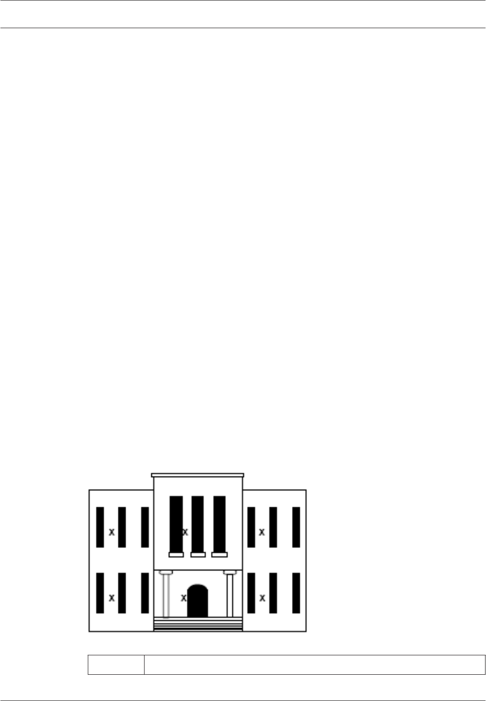
Figure 3.1: Coordinator/receiver locations
xCoordinator/Receiver location inside buillding
3
3.1
3.1.1
3.1.2
3.1.3
ALLPLEX track Coordinator & Receiver Mounting the Device | en 9
Robert Bosch (SEA) Pte Ltd Installation Guide 2014.03 | V1.0.0 | F.01U.277.701
Outdoor installation
Select a mounting location that:
– provides a clear line-of-sight of the protected area.
– is away from metallic objects such as chain-link fences and electrical transformers. If
coverage is required near such items, perform testing near them to determine the
potential need for additional receivers.
– is 3 m (10 ft.) above grade.
– is not at a barrier where it is important to resolve which side an alarm location is on.
– is easy to service.
– is not damaged by tampering.
Spacing
Mount coordinators/receivers every 90 m (300 ft.). It is very important to maintain spacing as
consistent as possible to ensure optimum signal locating. The more the coordinators/receivers
can detect a transmitted signal, the more accurate the locating. Make sure each coordinator/
receiver has a clear line-of-sight of the intended protection area.
Mounting height
Mount coordinators/receivers 3 m (10 ft.) above grade. Maintain a mounting height that is as
consistent as possible to ensure optimum signal locating.
Overhangs/eaves
Coordinator/receiver locations should be below building overhangs and eaves. Most
transmissions occur 1 m (a few feet) above grade. Therefore, mounting above overhangs and
eaves can result in inaccurate signal locating. Be especially careful around metal roofs as
these can block the signal.
Pre-wired installations
When mounting the enclosure to a pre-wired electrical box, make sure that the electrical box
has a 15.2 cm (6 in.) overhead clearance. The enclosure should be mounted as shown in figure
below.
Notice!
The enclosure does not currently support octagonal electrical boxes.
3.2
3.2.1
3.2.2
3.2.3
3.3
10 en | Mounting the Device ALLPLEX track Coordinator & Receiver
2014.03 | V1.0.0 | F.01U.277.701 Installation Guide Robert Bosch (SEA) Pte Ltd
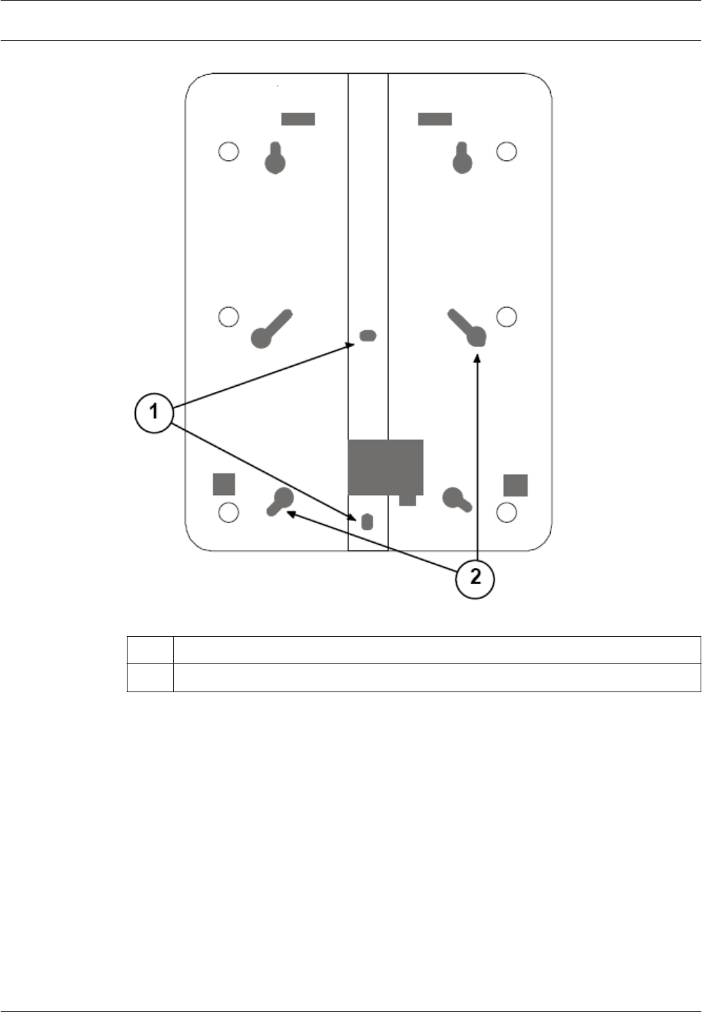
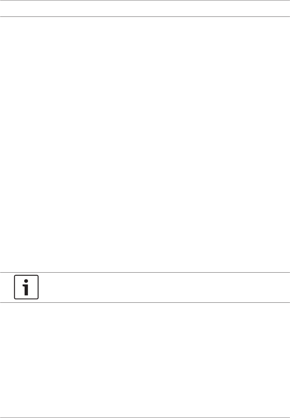
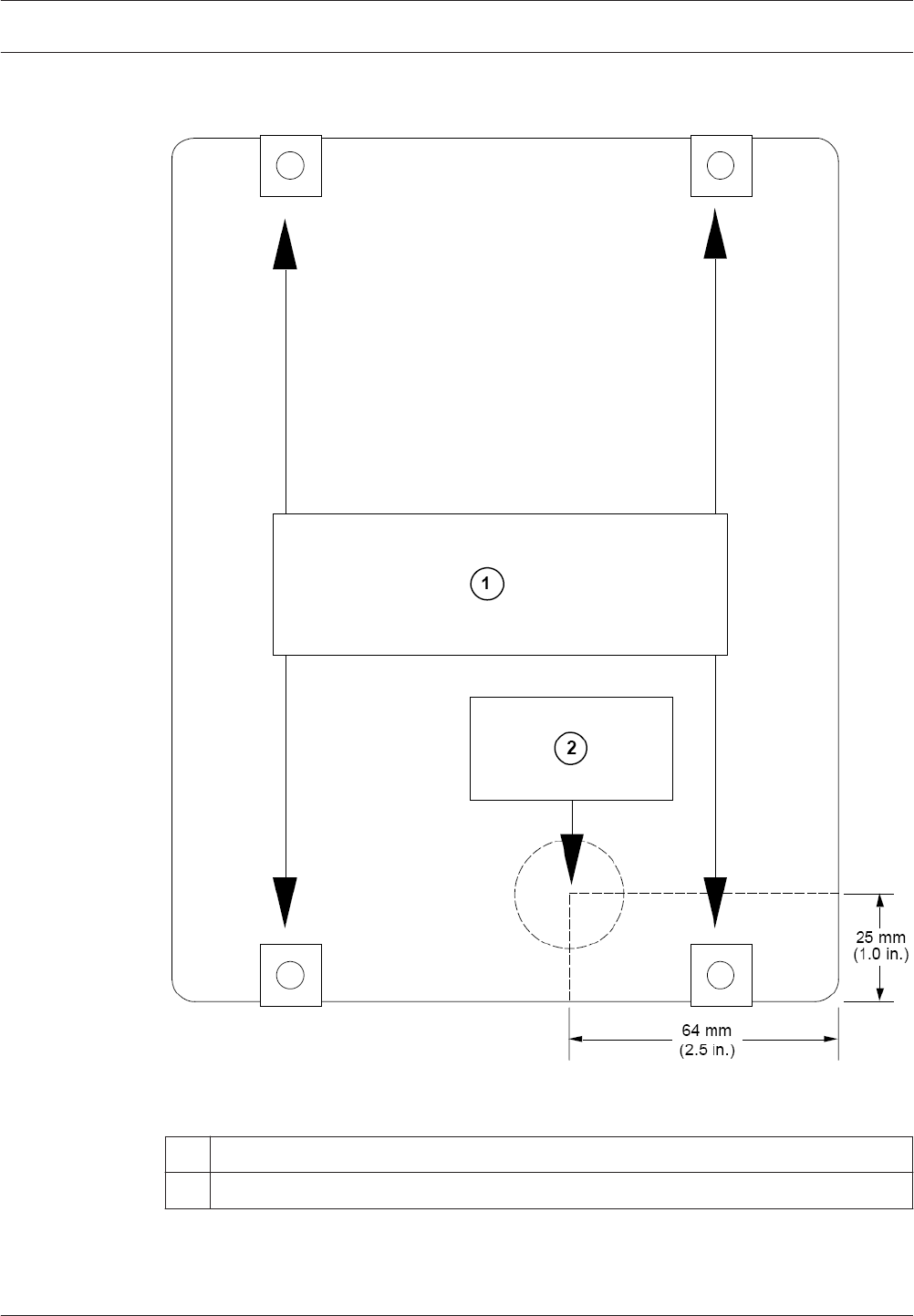
Figure 3.2: Back of indoor enclosure
1Use with single-gang electrical boxes
2 Use with 8.9 cm (3½ in.) square electrical boxes
Drilling templates
Use the following templates for mounting the outdoor enclosure. For enclosure with bottom
entry, see Drilling template for outdoor enclosure bottom entry, page 12. For enclosure with
rear entry, see Drilling template for outdoor enclosure rear entry, page 13.
3.4
ALLPLEX track Coordinator & Receiver Mounting the Device | en 11
Robert Bosch (SEA) Pte Ltd Installation Guide 2014.03 | V1.0.0 | F.01U.277.701
Drilling template for outdoor enclosure bottom entry
Figure 3.3: Drilling template bottom entry
1Align template with mounting hole squares on box
2 Drill here, 25 mm (1 in.) diameter maximum; 19 mm (¾ in.) conduit.
3 Bottom entry
3.4.1
12 en | Mounting the Device ALLPLEX track Coordinator & Receiver
2014.03 | V1.0.0 | F.01U.277.701 Installation Guide Robert Bosch (SEA) Pte Ltd
Drilling template for outdoor enclosure rear entry
Figure 3.4: Drilling template rear entry
1Align template with mounting holes on backside of box.
2 Drill here, 25 mm (1 in.) diameter maximum; 19 mm (¾ in.) conduit.
3.4.2
ALLPLEX track Coordinator & Receiver Mounting the Device | en 13
Robert Bosch (SEA) Pte Ltd Installation Guide 2014.03 | V1.0.0 | F.01U.277.701

Layout and Wiring of the Device
Danger!
Apply the electrical power only after all connections are completed and inspected.
This section identifies and locates the key components on the coordinator/receiver.
4
14 en | Layout and Wiring of the Device ALLPLEX track Coordinator & Receiver
2014.03 | V1.0.0 | F.01U.277.701 Installation Guide Robert Bosch (SEA) Pte Ltd
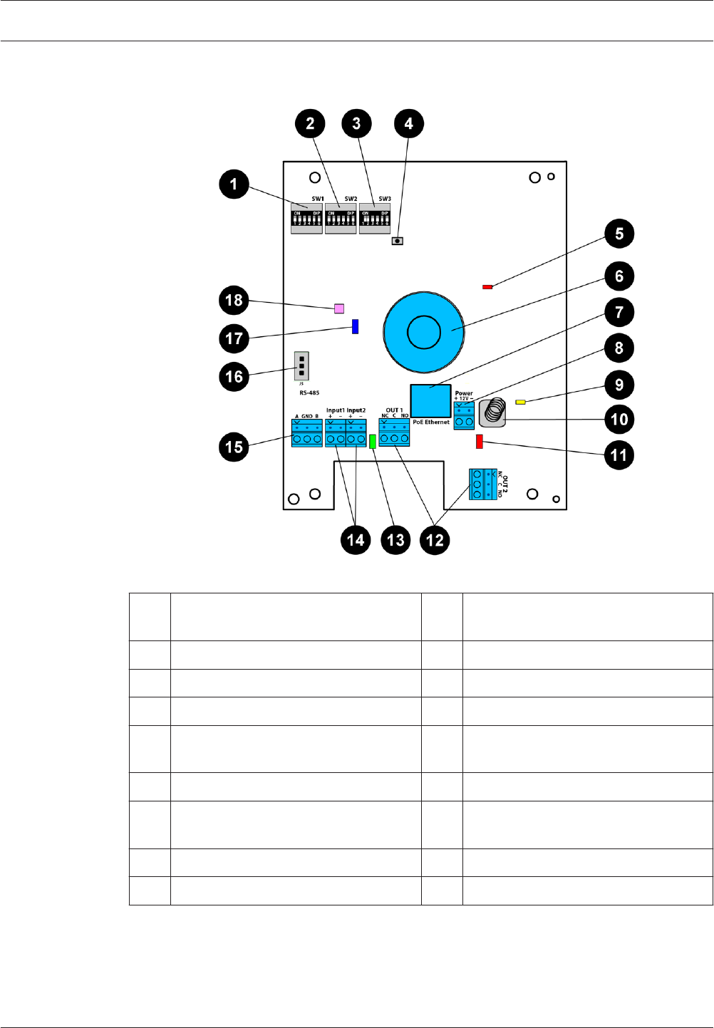
Layout of the coordinator/receiver
Figure 4.1: Layout of coordinator/receiver
1Dip switch SW1 (not available on
coordinator)
10 Tamper switch
2 Dip switch SW2 11 Red LED
3 Dip switch SW3 12 Output connectors
4 Reset button 13 Green LED
5 Power over Ethernet (PoE) LED (not
available on receiver)
14 Input connectors
6 Buzzer 15 RS-485 communication connector
7 Power over Ethernet (PoE) connector
(not available on receiver)
16 RS-485 jumpers
8 Power supply connector 17 Ethernet LED
9 Power supply LED 18 Tricolor LED
4.1
ALLPLEX track Coordinator & Receiver Layout and Wiring of the Device | en 15
Robert Bosch (SEA) Pte Ltd Installation Guide 2014.03 | V1.0.0 | F.01U.277.701
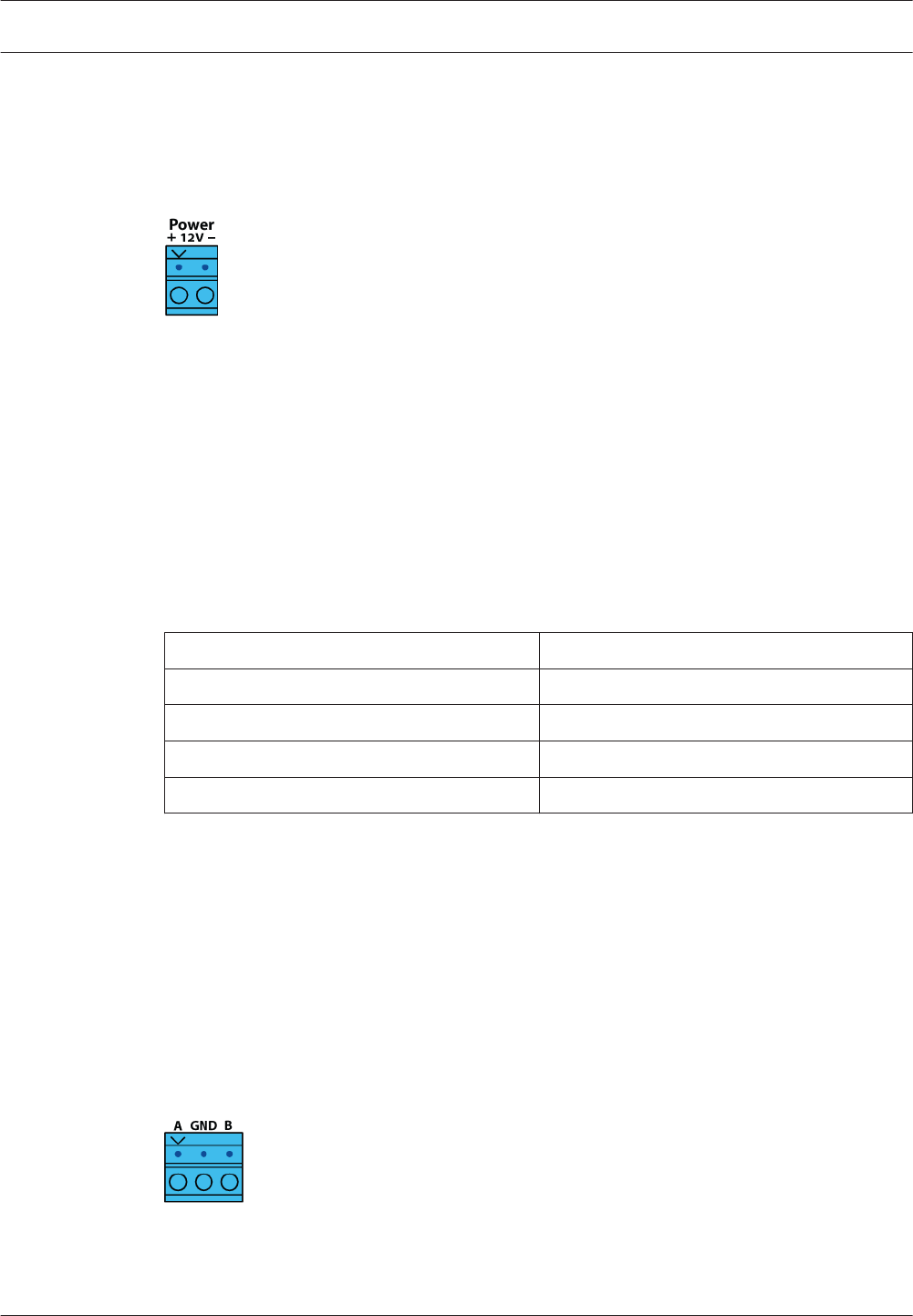
Power supply connector
The coordinator/receivers can be powered by an external 12V DC input. It consists of two
terminals: one of which is used to provide the positive input, and the other the negative input.
The operating input voltage range is 10.8 – 13.2V.
Figure 4.2: Power Supply Connector
Power over Ethernet (PoE) connector
Power over Ethernet (PoE) is applicable to coordinators only. Receivers do not have the
Ethernet interface ports. The coordinators can be powered by PoE without needing an
external DC input. The PoE connector is identified by the label PoE Ethernet on the
coordinator. Connect the PoE using the standard Cat 5e Ethernet cable and above. PoE
provides the maximum total power of 12.95 Watt to the coordinator, and complies with the
IEEE802.3af class 0 standard.
The coordinator also sends any received data from the receivers or transmitters to the Central
Console Software via the Ethernet cable. The coordinator is pre-configured with the following
default IP settings:
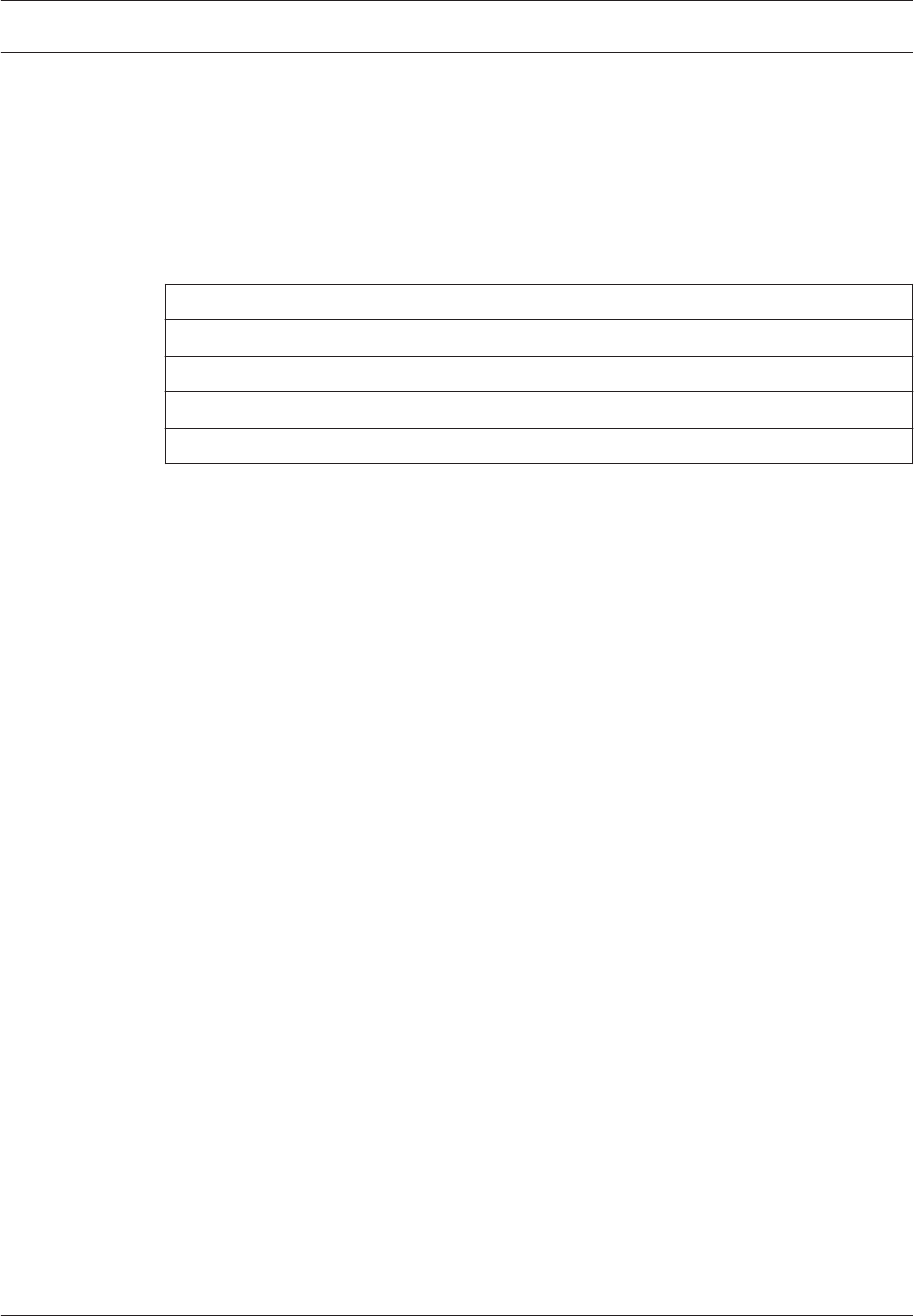
IP Settings Value
IP Address 192.168.1.100
Subnet Mask 255.255.255.0
Gateway 192.168.1.1
Port 20000
Table 4.1: Default IP Settings of Coordinator
The default settings can be changed using the Utility Tool from the Security Escort software.
See the Security Escort Installation and Setup Manual for more information.
RS-485 communication connector
The coordinator and receivers can communicate with each other using the RS-485 interface.
The communication connector is identified by their 3 terminal points, namely A, GND and B.
The recommended data transmission speed is 19200 bps @ 1km (default) and 115 kbps @
500m. For outdoor installations, the recommended wiring for RS-485 communication is
shielded twisted-pair.
Figure 4.3: RS-485 Connector
4.2
4.3
4.4
16 en | Layout and Wiring of the Device ALLPLEX track Coordinator & Receiver
2014.03 | V1.0.0 | F.01U.277.701 Installation Guide Robert Bosch (SEA) Pte Ltd
RS-485 jumpers
The coordinator and receivers use RS-485 multi-drop communication channels between the
device boards. It is necessary to include end-of-line jumper settings on the last receiver to
have a stable communication channel (see Setting the jumpers for RS-485 communication loop,
page 24). The jumper blocks are identified as J5 on the coordinator/receiver.
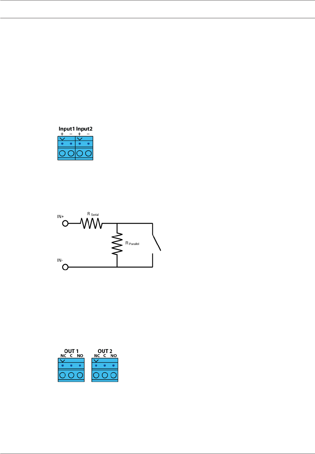
Input connectors
Two 2-pin connectors on the left side of the coordinator/receiver provide terminal points for
wiring from input devices. The terminal strips are identified as Input1 and Input2 on the
coordinator/receiver. There are two terminals for each input point.
Figure 4.4: Input Connectors
Each input point supports four-state supervised mode. To detect the four states, there are
special values allowed for potential drop depending on the resistors used. The coordinator/
receiver can also detect short and open wiring conditions and initiate an alarm if the
appropriate devices are connected.
Figure 4.5: Circuit Diagram for Resistors
RS = RP = 2.2 kΩ ¼W
Output connectors
Two 3-pin connectors provide terminal points for connection of external devices. The
connectors are identified as OUT 1 and OUT 2 on the coordinator/receiver. The output
terminals are Form-C type relay dry contacts. For each relay, Normally Closed (NC), Normally
Open (NO) and Common (C) terminals are provided.
Figure 4.6: Output Connectors
LED indicators
The following section describes the behaviors of the various LEDs upon device start up and
during system operation.
Power supply LED
– The LED will light up in orange as long as the coordinator/receiver is powered by the DC
input.
4.5
4.6
4.7
4.8
ALLPLEX track Coordinator & Receiver Layout and Wiring of the Device | en 17
Robert Bosch (SEA) Pte Ltd Installation Guide 2014.03 | V1.0.0 | F.01U.277.701
Power over Ethernet (PoE) LED
– The LED will light up in red as long as the coordinator is powered by the PoE input.
Green LED
– For every successful transmitter test, the LED will briefly light up in green.
Red LED
– For every alarm or specific system test in progress, the LED will briefly light up in red.
Tricolor LED
– Upon coordinator/receiver start up
– the LED blinks a number of times in white to indicate the current radio frequency
(RF) configuration as set by the dip switch (see Checking the radio frequency (RF),
page 27)
– Coordinator/receiver communicating via RS-485
– the LED blinks in pink every 3 seconds
– Coordinator/receiver communicating via RF when RS-485 is not working
– the LED blinks in green for any transmission events if the signal strength is excellent
– the LED blinks in blue for any transmission events if the signal strength is average
– the LED blinks in red for any transmission events if the signal strength is poor
– If there is no communication between the coordinator and receiver, the LED does not
light up.
Notice!
The power supply, PoE and tricolor LEDs are only visible if you remove the casing enclosure.
Tamper switch
To protect the coordinator/receiver against unauthorized access, an additional interface to
detect tamper contact is used. The tamper switch is triggered when the coordinator/receiver
is not covered in the casing enclosure. This event is monitored and reported to the Central
Console Software where any subsequent actions are determined by the configured software
settings. It is recommended that the coordinator/receiver should be covered in the casing at
all times.
Reset button
A reset button is available on the coordinator/receiver. This button can be used to perform a
hard or soft factory reset based on the associated dip switch setting (see Selecting the hard/
soft reset mode, page 21). Depending on the hard or soft reset, pressing it will clear specific
sets of configuration for the device. For more information, please refer to Resetting the
coordinator/receiver, page 27.
4.9
4.10
18 en | Layout and Wiring of the Device ALLPLEX track Coordinator & Receiver
2014.03 | V1.0.0 | F.01U.277.701 Installation Guide Robert Bosch (SEA) Pte Ltd
Setting the Switches and Jumpers
There are three dip switches on the receiver, namely SW1 on the left, SW2 in the middle and
SW3 on the right. Dip switch SW1 is not mounted on the coordinator. Therefore, only dip
switches SW2 and SW3 are available on the coordinator. Use the dip switches to configure
settings like the address of the device and the radio frequency, or the operation settings like
usage of soft or hard reset.
Figure 5.1: Dip switches
The usage of the dip switches are explained as of below:
Dip Switch Switch Number Usage
SW1 (receiver only) 1 Address of Device
2
3
4
5 Not Used
6
SW2 1 Frequency Selection
2
3 Hard/Soft Reset Mode
4 Baud Rate
5
6 Disable/Enable Buzzer
SW3 1 Spacing Selection
2 Transmit Mode
3 Not Used
4
5
6
Table 5.1: Usage of dip switches
Usage of the dip switches will be explained in detail in the respective sections.
Notice!
Take note that switch number 5 and 6 on dip switch SW1 and switch number 3, 4, 5 and 6 on
dip switch SW3 are currently not being used.
5
ALLPLEX track Coordinator & Receiver Setting the Switches and Jumpers | en 19
Robert Bosch (SEA) Pte Ltd Installation Guide 2014.03 | V1.0.0 | F.01U.277.701
Notice!
It is recommended to power off the coordinator/receiver before you change the dip switch
settings. Upon completing the changes, power up the devices. The new settings will only take
into effect once the coordinator/receiver completed a power reset cycle.
Setting the loop address
Use the address dip switch to configure the RS-485 loop address of the receiver. Each
coordinator/receiver on a loop must have its own unique address. Only addresses 0 through
15 are valid.
The coordinator always uses address 0. You do not need to set the address for the
coordinator. Therefore, the dip switch SW1 used for setting addresses is not available on the
coordinator. The receivers use addresses 1 to 15. Set the address using dip switch SW1.
Configure the four switches from the left, 1, 2, 3 and 4 as the address of the device.
Address Switch Number on Dip Switch SW1
1 2 3 4
0
(used for
coordinator only)
OFF OFF OFF OFF
1
(default setting
for receiver)
ON OFF OFF OFF
2 OFF ON OFF OFF
3 ON ON OFF OFF
.
.
.
.
.
.
.
.
.
.
.
.
.
.
.
15 ON ON ON ON
Table 5.2: Address settings on dip switch SW1
Setting the radio frequency (RF)
Use the radio frequency (RF) switches on dip switch SW2 to configure the RF of the device.
Set the two switches from the left, 1 and 2 according to the following table.
Radio Frequency Switch Number on Dip Switch SW2
1 2
304 MHz (default setting) OFF OFF
303.825 MHz OFF ON
5.1
5.2
20 en | Setting the Switches and Jumpers ALLPLEX track Coordinator & Receiver
2014.03 | V1.0.0 | F.01U.277.701 Installation Guide Robert Bosch (SEA) Pte Ltd
Radio Frequency Switch Number on Dip Switch SW2
1 2
433.42 MHz ON OFF
Invalid setting ON ON
Table 5.3: Radio frequency (RF) settings on dip switch SW2
Once configured, you can confirm the RF settings every time you power up the coordinator/
receiver by observing the tricolor LED. For more information, refer to Checking the radio
frequency (RF), page 27.
Selecting the hard/soft reset mode
There are two reset modes for the coordinator/receiver, namely the hard or soft reset. To
select the reset mode, use dip switch SW2. Set switch number 3 based on the following table.
Reset Mode Switch Number on Dip Switch SW2
3
Soft reset (default setting) OFF
Hard reset ON
Table 5.4: Reset mode on dip switch SW2
Pressing the Reset button on the coordinator/receiver performs the hard or soft reset
accordingly. The differences of the reset mode are described in Resetting the coordinator/
receiver, page 27.
Setting the baud rate
Configure the baud rate of the RS-485 communication by using the dip switch on the right,
SW2. The same baud rate must be set across the coordinator and the receivers in order for
the RS-485 communication to work. Use the switch numbers 4 and 5 on dip switch SW2 to set
the baud rate. The options are described in the following table.
Baud Rate Switch Number on Dip Switch SW2
4 5
19200 (default setting) OFF OFF
38400 OFF ON
57600 ON OFF
115200 ON ON
Table 5.5: Setting the baud rate on dip switch SW2
5.3
5.4
ALLPLEX track Coordinator & Receiver Setting the Switches and Jumpers | en 21
Robert Bosch (SEA) Pte Ltd Installation Guide 2014.03 | V1.0.0 | F.01U.277.701
Enable/disable the buzzer
Enable or disable the buzzer by setting the buzzer dip switch. Set switch number 6 on dip
switch SW2 to the OFF position to disable the buzzer. Once disabled, the buzzer will be
muted at all times, including during alarm events. Set switch number 6 on dip switch SW2 to
the ON position to enable the buzzer to be operational. Once enabled, the buzzer will sound
whenever triggered accordingly by the alarm events.
Enable/disable Buzzer Switch Number on Dip Switch SW2
6
Disable Buzzer (default setting) OFF
Enable Operational Buzzer ON
Table 5.6: Enable or disable the buzzer on dip switch SW2
Enable/disable the spacing mode
Spacing mode can be used to verify the maximum acceptable spacing of receivers. Enable or
disable the spacing mode by setting switch number 1 on dip switch SW3. Spacing mode is
disabled by default, where switch number 1 is set to the OFF position. To enable the spacing
mode, set switch number 1 on dip switch SW3 to the ON position.
Enable/disable Spacing Mode Switch Number on Dip Switch SW3
1
Disable Spacing Mode (default setting) OFF
Enable Spacing Mode ON
Table 5.7: Enable or disable the spacing mode on dip switch SW3
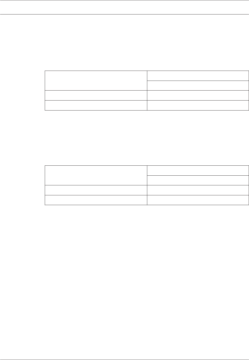
To test the spacing of receivers:
1. Mount the first receiver (receiver 1). Set switch number 1 on dip switch SW3 to the ON
position. Power the receiver from a 12 VDC source.
2. Take the second receiver (receiver 2) and a transmitter a distance away from the first
receiver.
3. Activate the transmitter.
4. If receiver 1 sounds the test beep, receiver 2 is within range. Repeat this test until
receiver 1 no longer sounds the test beeps. Move back to the last location where receiver
1 received the test beeps. This location marks the maximum spacing between the
receivers. The distance between the receivers should not exceed 25 m (80 ft.) indoors
and 90 m (300 ft.) outdoors. Mount receiver 2 at this location or closer to receiver 1.
5.5
5.6
22 en | Setting the Switches and Jumpers ALLPLEX track Coordinator & Receiver
2014.03 | V1.0.0 | F.01U.277.701 Installation Guide Robert Bosch (SEA) Pte Ltd
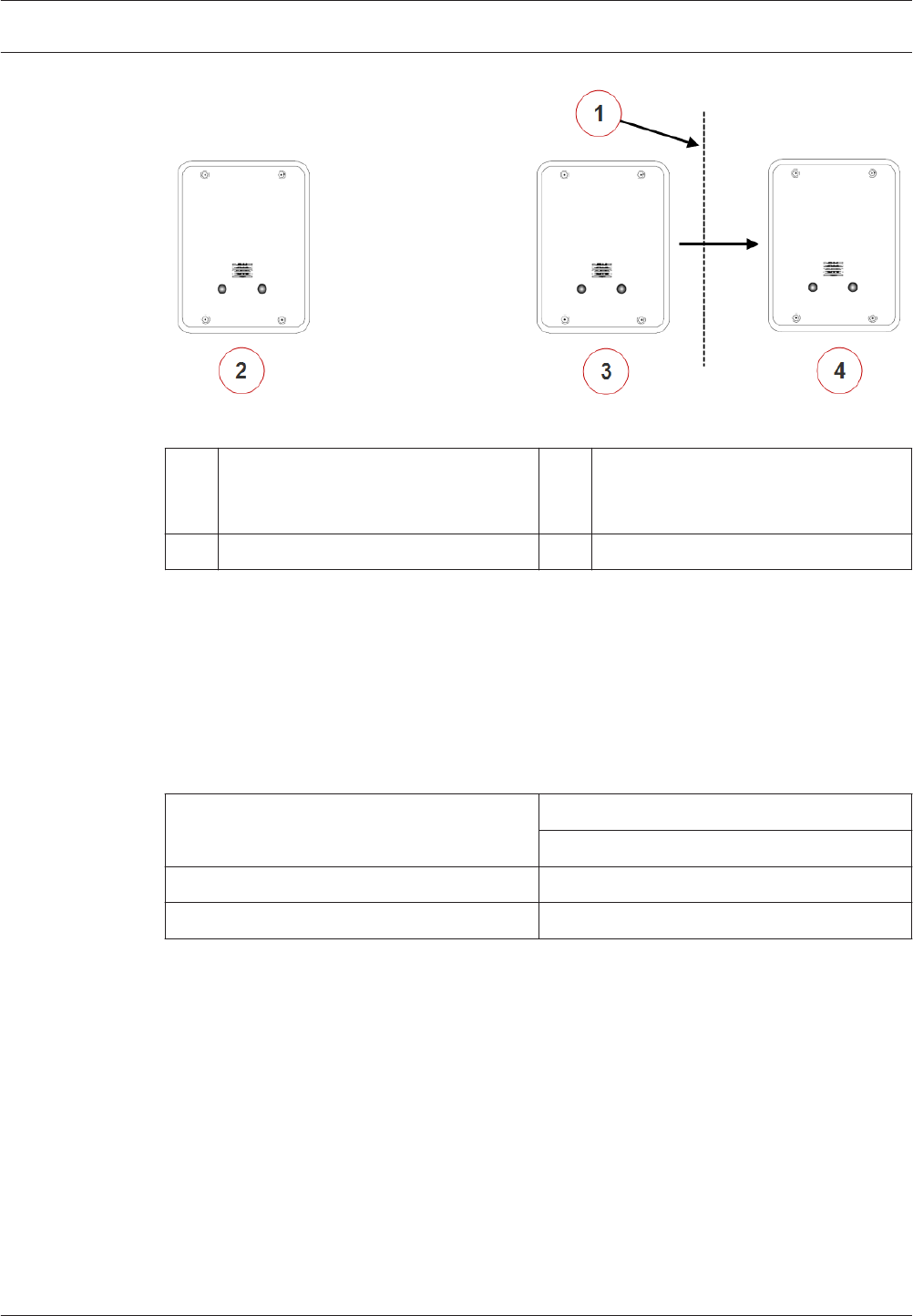
Figure 5.2: Receiver Spacing
1Receiver 1 stops sounding the test
beeps when receiver 2 is moved past
this point
3 Receiver 2 at maximum range
2 Receiver 1 4 Receiver 2 beyond maximum range
Enable/disable the transmit mode
Transmit mode can be used to verify the maximum acceptable spacing of receivers from the
coordinator using the radio frequency communication. When the transmit mode is enabled on
the receiver, it will communicate with the coordinator continuously. Enable or disable the
transmit mode by setting switch number 2 on dip switch SW3. Transmit mode is disabled by
default, where switch number 2 is set to the OFF position. To enable the transmit mode, set
switch number 2 on dip switch SW3 to the ON position.
Enable/disable Transmit Mode Switch Number on Dip Switch SW3
2
Disable Transmit Mode (default setting) OFF
Enable Transmit Mode ON
Table 5.8: Enable or disable the transmit mode on dip switch SW3
The following is applicable when using the radio frequency as the communication channel.
Transmit Mode is enabled with switch number 2 of dip switch 3 on the AT receiver (see the
ALLPLEX track Coordinator & Receiver Installation Guide). Only transmissions with an adequate
receive margin will light up the green LEDs. This indicates the maximum acceptable spacing of
the AT receiver.
To test the spacing of the receivers:
1. Activate the spacing mode on the coordinator (see Enable/disable the spacing mode, page
22). Set switch number 1 on dip switch SW3 to the ON position.
5.7
ALLPLEX track Coordinator & Receiver Setting the Switches and Jumpers | en 23
Robert Bosch (SEA) Pte Ltd Installation Guide 2014.03 | V1.0.0 | F.01U.277.701
2. Activate the transmit mode on the receiver. Set switch number 2 on dip switch SW3 to
the ON position. Power the receiver from a 12 VDC source. The receiver will start
transmitting messages to the coordinator continuously. This communication is indicated
by the blinking LED.
3. If the receiver is within the range, the LED will continue to blink. Move the receiver away
from the coordinator until the green LED stops blinking. This indicates that the receiver is
now beyond the maximum range. Move back to the last location where the coordinator is
able to receive the transmission from the receiver. This location marks the maximum
spacing between the coordinator and the receiver. The distance between the coordinator
and the receiver should not exceed 25 m (80 ft.) indoors and 90 m (300 ft.) outdoors.
Figure 5.3: Coordinator and Receiver Spacing
1LED of the coordinator stops blinking
when the receiver is moved past this
point
3 Receiver at maximum range
2 Coordinator 4 Receiver beyond maximum range
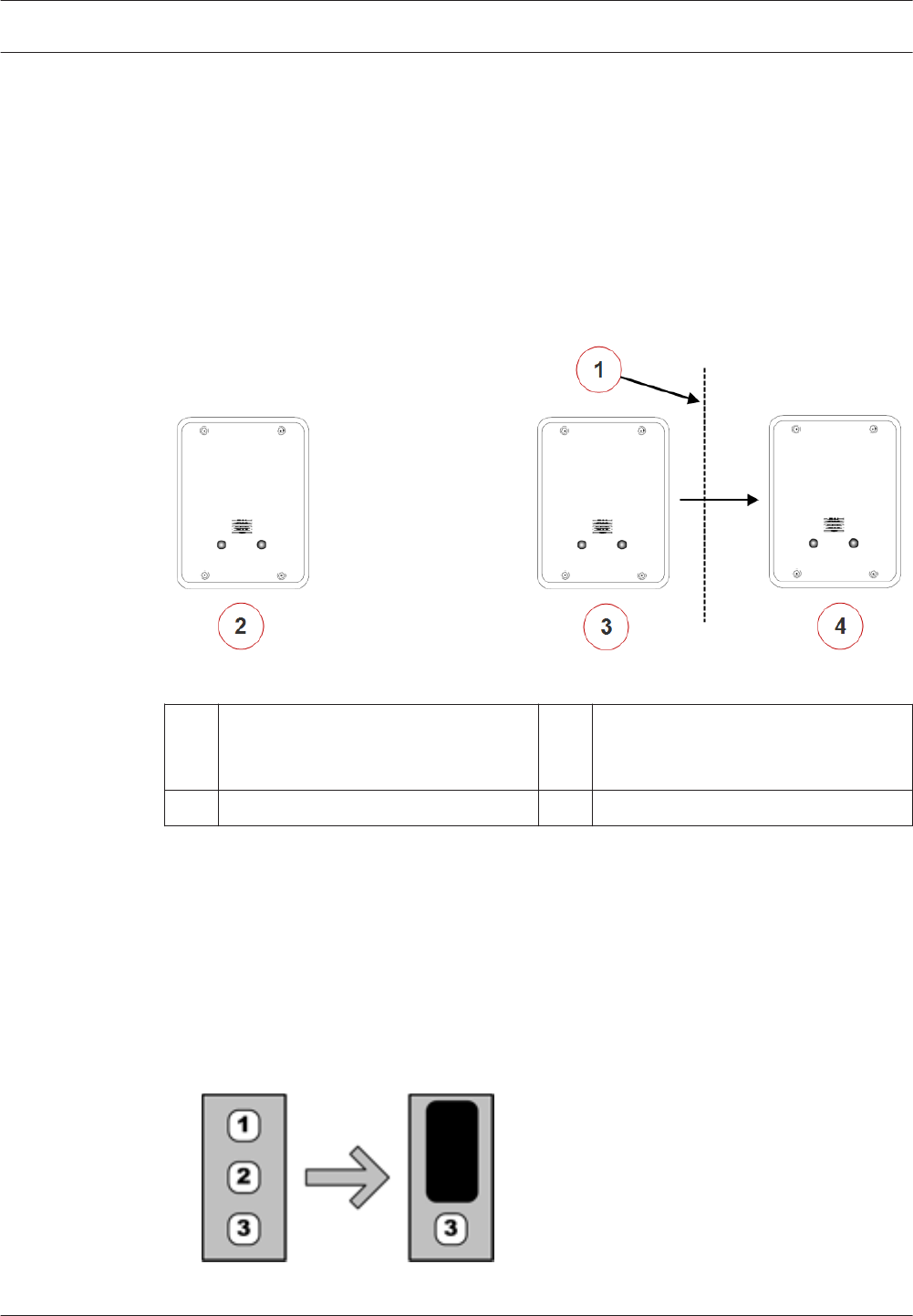
Setting the jumpers for RS-485 communication loop
For RS-485 communication, it is necessary to include the end of line jumper settings on the
last receiver to have a stable communication channel. Set the jumper for the coordinator and
the last receiver as of below:
1. For the coordinator, locate the jumper block J5 and set the jumper over the jumper pins 1
and 2 (default setting on coordinators).
5.8
24 en | Setting the Switches and Jumpers ALLPLEX track Coordinator & Receiver
2014.03 | V1.0.0 | F.01U.277.701 Installation Guide Robert Bosch (SEA) Pte Ltd
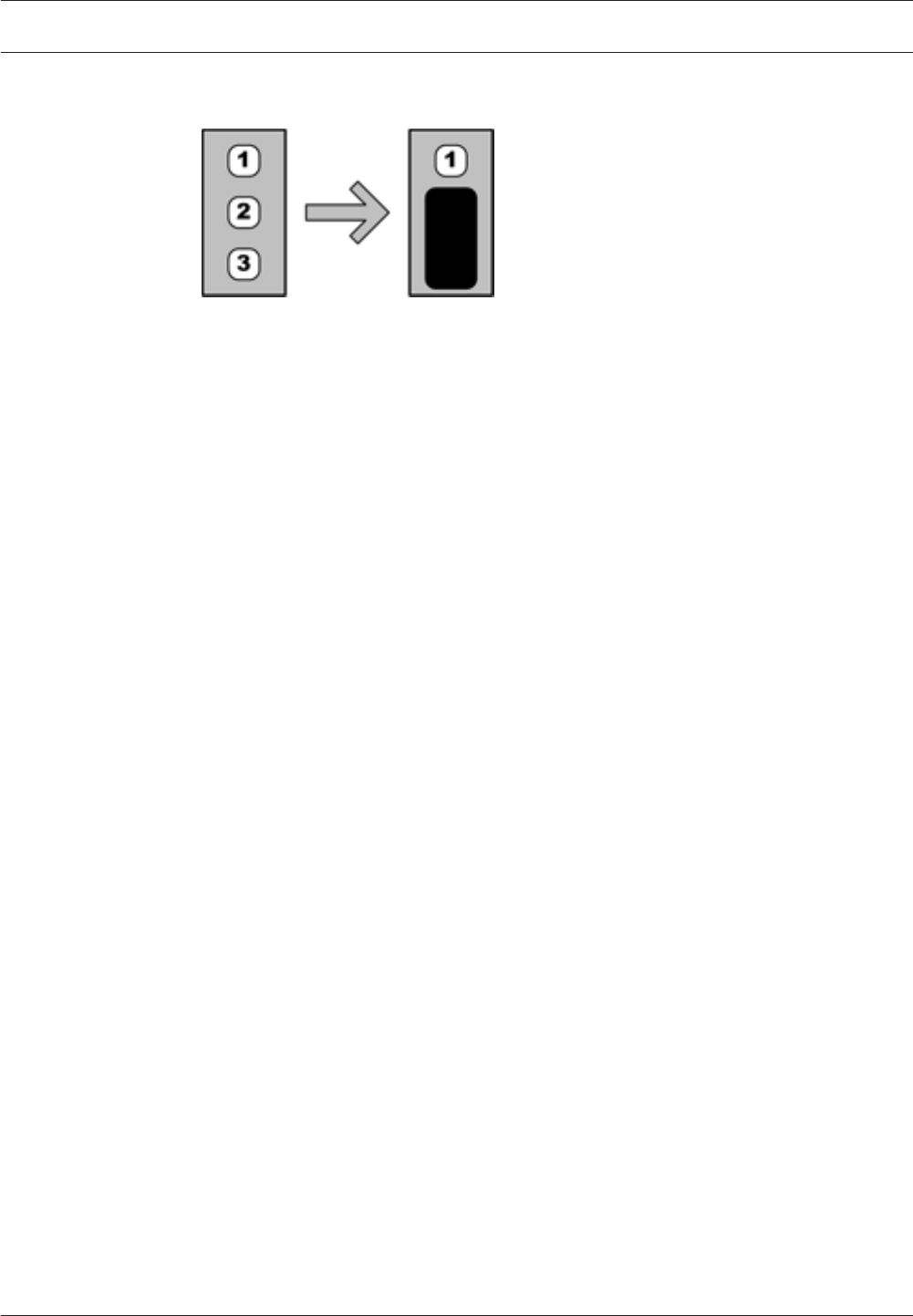
2. For the last receiver, locate the jumper block J5 and set the jumper over the jumper pins
2 and 3 (default setting on receivers).
ALLPLEX track Coordinator & Receiver Setting the Switches and Jumpers | en 25
Robert Bosch (SEA) Pte Ltd Installation Guide 2014.03 | V1.0.0 | F.01U.277.701

Troubleshooting the Device
This section offers troubleshooting guidance for situations when there are issues with the
coordinator/receiver. Upon powering up the device, there are visual indicators that provide
information about the current state or configuration of the devices. If these indicators behave
differently from what is expected, there could be issues that need to be addressed. The
following information can be helpful to determine potential issues.
Take note that the following LED indicators are only visible if the casing enclosure of the
device is temporarily removed:
– Power supply LED
– Tricolor LED
– Ethernet LED
– Power over Ethernet (PoE) LED (on the coordinator only)
Checking the power supply
When you power up the coordinator/receiver using the external DC input, the power supply
LED on the device will light up in orange. The LED will continue to illuminate as long as power
is supplied to the device. If the LED is not illuminated, there could be issues with the power
supply. Check that the operating input voltage is between the range specified (see Power
supply connector, page 16). If there is no power, check the cable or power supply to ensure
that it is not faulty. If there are no faults with the cable or power supply, check the
coordinator/receiver.
Checking Power over Ethernet (PoE)
Power over Ethernet (PoE) is only applicable for coordinators. Power for the coordinator can
be supplied via the Cat 5e cable using the PoE technology. When powered by the PoE, the PoE
LED will light up continuously in red color. If the LED is not illuminated, check that the Cat 5e
cable or the power sourcing equipment (for example, the network switch supplying the PoE)
is not faulty.
Checking Ethernet network issues
Ethernet network communication is only applicable for coordinators. The coordinator
communicates with the Central Console via Ethernet TCP/IP. If the coordinator uses an IP
address that is already in use by another device on the Ethernet network, an IP address
conflict occurs. This will render one or both the devices to be unable to connect to network
resources or perform other network operations.
If an IP address conflict is detected by the coordinator, the green and red LED will blink
continuously (500ms on, 500ms off). To rectify the issue, change the IP address of the
conflicting device using the Utility Tool of the Security Escort software, and blah blah blah (…
to be confirmed).
Checking the RS-485 communication
The coordinator and receivers communicate with each other via RS-485 by default. The
tricolor LED on the device will blink in pink light every 3 seconds as long as RS-485
communication is available. If the RS-485 communication is broken, the coordinator and
receivers will switch to radio frequency (RF) as the communication channel. As a result, the
behavior and color of the tricolor LED will no longer be the same (blink in pink light every 3
seconds). To troubleshoot RS-485 communication, check that the following is working:
1. RS-485 is enabled on the host system configuration.
6
6.1
6.2
6.3
6.4
26 en | Troubleshooting the Device ALLPLEX track Coordinator & Receiver
2014.03 | V1.0.0 | F.01U.277.701 Installation Guide Robert Bosch (SEA) Pte Ltd
2. Wiring of RS-485 is not faulty.
3. Baud rate settings (configured via dip switch) on the coordinator/receivers are the same.
Checking the radio frequency (RF)
If the coordinator and receivers are communicating via radio frequency (RF), you can confirm
the RF configuration by checking the tricolor LED visually. Every time you power up the device,
the LED will illuminate and blink a number of times in white light. The number of blinks on the
LED corresponds to the configured RF, as shown in the following table.
Radio Frequency Number of Blinks
304 MHz (default factory setting) Two
303.825 MHz One
433.42 MHz Three
Invalid setting Non-stop
Table 6.1: LED behavior upon powering up the device
If the selected RF is incorrect, set the dip switches accordingly and reconfirm the settings
with the procedure above.
Resetting the coordinator/receiver
Incorrect configurations on the coordinator or receiver may sometimes be the cause of issues
that you encounter. In instances like these, the issue may be cleared by simply performing a
reset on the coordinator/receiver. Depending on hard or soft reset, the reset cycle clears
specific sets of configuration to the factory settings. Pressing the reset button initiates the
reset cycle of the coordinator/receiver, with the red and green LEDs blinking once
simultaneously to indicate a hard reset, and the red and green LEDs blinking twice
simultaneously for a soft reset. The device is then powered up automatically with the factory
settings. For a list of settings or features that are being reset, please refer to the Appendix
Differences between hard and soft reset mode on the coordinator/receiver, page 28.
Upgrading coordinator/receiver firmware
Use the Utility Tool of the Security Escort software to check/upgrade the coordinator/receiver
firmware. For more information on the usage of Utility Tool, please refer to the Security Escort
Installation and Setup Manual.
6.5
6.6
6.7
ALLPLEX track Coordinator & Receiver Troubleshooting the Device | en 27
Robert Bosch (SEA) Pte Ltd Installation Guide 2014.03 | V1.0.0 | F.01U.277.701

Appendices
Differences between hard and soft reset mode on the
coordinator/receiver
The table below lists the different configurations that were cleared when performing the hard
or soft resets.
Reset on device Settings/Features Hard Reset Soft Reset
Coordinator Name of device ✓
IP ✓
Subnet mask ✓
Gateway ✓
RF enable/disable ✓ ✓
RS485 enable/disable ✓ ✓
Internal tamper
enable/disable
✓ ✓
Fail siren enable/
disable
✓ ✓
Verbose enable/
disable
✓ ✓
Test/Engineering
settings
✓ ✓
Receiver table ✓ ✓
Receiver Host coordinator ✓ ✓
Table 7.1: Differences between hard and soft reset
7
7.1
28 en | Appendices ALLPLEX track Coordinator & Receiver
2014.03 | V1.0.0 | F.01U.277.701 Installation Guide Robert Bosch (SEA) Pte Ltd

Robert Bosch (SEA) Pte Ltd
11 Bishan Street 21
573943 Singapore
Singapore
www.boschsecurity.com
© Robert Bosch (SEA) Pte Ltd, 2014