Bosch Security Systems ATX-CR-RV Allplex track User Manual ALLPLEX track Coordinator
Bosch Security Systems, Inc. Allplex track ALLPLEX track Coordinator
Contents
- 1. Users Manual
- 2. installation manual
Users Manual
Engineered Solutions | ALLPLEX track Coordinator
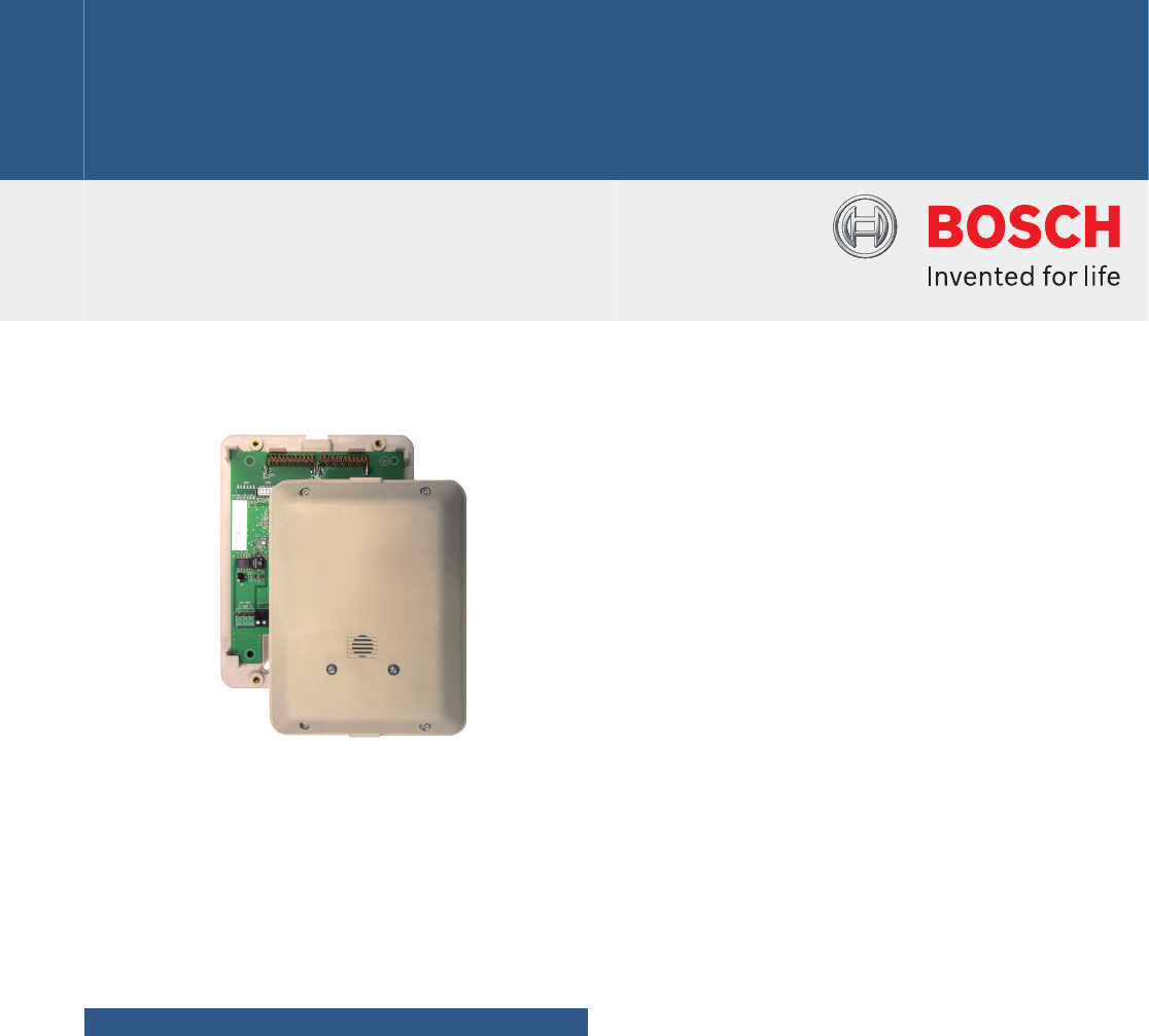
ALLPLEX track Coordinator
www.boschsecurity.com
uDevice controller for up to 15 receivers
uPowered using Power over Ethernet (PoE)
uWired TCP/IP to the host central console
uWired (RS-485) or wireless communication to
receiver
uSelectable frequencies of 303.825 / 304 / 433.42
MHz
uRemote firmware upgradable via wired TCP/IP
uBuilt-in 2 inputs and 2 relay outputs
The ALLPLEX track coordinator is a device controller
for up to 15 ALLPLEX track receivers. Its primary
function is to monitor the receivers, and report
conditions and events to the central console over
wired Ethernet (TCP/IP). The coordinator can be
powered using Power over Ethernet (PoE).
Functions
Function during alarm
• When a receiver detects an alarm, it goes into an
Off‑Normal state. To quickly locate any devices which
might be in the Off‑Normal State, the coordinator
issues global commands that are interpreted
simultaneously by all of its devices approximately ten
times per second.
• The coordinator sends commands to specific devices
to determine the nature of the Off‑Normal condition.
During an alarm or test, the coordinator sends
commands to obtain the transmitter identification
number, transmitter battery condition, and received
signal strength.
• The alarm information is sent by the receiver to the
coordinator either by wired RS-485 or through
wireless radio frequency.
• The alarm information is then relayed by the
coordinator to the central console by wired Ethernet
(TCP/IP), where it graphically shows the identity and
location of the subscriber (user) sending the alarm.
Configuration
The coordinator identifies each receiver by its address.
The address is set during system installation using a
DIP switch on the receiver circuit board. Coordinators
communicate on the data bus with individual devices
by issuing commands, which contain the receiver’s
address.
Setup and testing
Upon setting up each coordinator and connected
devices, they can be tested remotely from the central
console. Also, each coordinator reports any problems,
such as low battery, immediately upon detecting them.
Alarm input and relay output control
The coordinator has two analog inputs and two relay
outputs. The analog inputs are monitored and support
4 state supervised modes. The coordinator can detect
short/open wiring conditions, and initiate an alarm if
the appropriate input devices are connected. Each
relay output provisions for normally open (NO),
normally closed (NC) and common (C) terminals.
Certifications and approvals
The product is classified in accordance with the
following standards:
• FCC part 15.231
• ETSI EN300 (433.42 Mhz)
• RCM
Installation/configuration notes
Installation
The coordinator is for indoor and outdoor use. The
coordinator mounts in one of two different sized
enclosures. Connect the receivers to the coordinator
using one 3‑wire multiplex buses: two wires for data
(A and B) and one wire for GND. Each bus supports 1
built-in receiver of the coordinator and up to 15
external receivers. A Security Escort System supports
up to 1024 coordinators and a total of 16384 devices.
Mounting Considerations
You will need a Security Hex Driver to mount the
receiver.
•Indoor Enclosure: Mount on inside walls.
•Outdoor Enclosure: Mount on the sides of buildings
and on light posts.
Compatibility Information
Central Console
Software
SE3000 Series
AT receiver ATX-RCV-MT01
AT transmitter ATX-TRM-304T01, ATX-TRM-433T01
Transmitter SE2 Series, SE3 Series, SE3401 and SE88
Series
Parts included
Quantity Component
1ALLPLEX track Coordinator
1 ALLPLEX track Coordinator & Receiver Installation Manual
4 2.2 kΩ Axial Lead Resistors
Technical specifications
Transmission
Frequency 303.825 / 304 (default) / 433.42 MHz
selectable by Dip Switch
Trouble Output Signal sent through the central console
Antenna Type Internal
Sensitivity
Adjustments
-100 dB minimum
Electrical
Power Consumption 200mA @ +12VDC (max)
Operating Input
Voltage
10.8 – 13.2V
Primary Power
Source
Power over Ethernet (PoE)
(PoE standard: IEEE 802.3af-2003 and IEEE
802.3at-2009 Type 1)
Secondary Power
Source
12V DC in
Environmental
Operating
Temperature
-30°C to +65°C
(-22°F to +149°F)
Hardware
Input 2 analog inputs
(4 state supervised monitoring)
Output 2 relay outputs
(Relay dry contact, 1A @ 30V DC)
Communication
Interface
Ethernet 10/100 BaseT (central console)
RS-485 / Wireless radio frequency (receivers)
Housing Tamper Normally closed (NC)
Reliability
Mean Time Between
Failures (MTBF)
10 years
Ordering information
ALLPLEX track Coordinator
Controls ALLPLEX track receivers. Relays alarm and
test signals from the receivers to the central console.
Selectable frequencies of 303.825 / 304 / 433.42 MHz
by dip switch.
Order number ATX-COR-MT01
2 | ALLPLEX track Coordinator

3 | ALLPLEX track Coordinator
Represented by:
Americas: Europe, Middle East, Africa: Asia-Pacific: China: America Latina:
Bosch Security Systems, Inc.
130 Perinton Parkway
Fairport, New York, 14450, USA
Phone: +1 800 289 0096
Fax: +1 585 223 9180
security.sales@us.bosch.com
www.boschsecurity.us
Bosch Security Systems B.V.
P.O. Box 80002
5617 BA Eindhoven, The Netherlands
Phone: + 31 40 2577 284
Fax: +31 40 2577 330
emea.securitysystems@bosch.com
www.boschsecurity.com
Robert Bosch (SEA) Pte Ltd, Security
Systems
11 Bishan Street 21
Singapore 573943
Phone: +65 6571 2808
Fax: +65 6571 2699
apr.securitysystems@bosch.com
www.boschsecurity.asia
Bosch (Shanghai) Security Systems Ltd.
201 Building, No. 333 Fuquan Road
North IBP
Changning District, Shanghai
200335 China
Phone +86 21 22181111
Fax: +86 21 22182398
www.boschsecurity.com.cn
Robert Bosch Ltda Security Systems Division
Via Anhanguera, Km 98
CEP 13065-900
Campinas, Sao Paulo, Brazil
Phone: +55 19 2103 2860
Fax: +55 19 2103 2862
latam.boschsecurity@bosch.com
www.boschsecurity.com
© Bosch Security Systems 2014 | Data subject to change without notice
8008436747 | en, V1, 17. Jul 2014