Boston Scientific CRMV17311 K172, K173, K174, K175, K176, K177, K062, K063, K064, K065, K066, K067, K272, K 273, K274, K275, K276, K277, V272, V273, V172, V173, K278, K279 User Manual wrench rotation side
Boston Scientific Corporation K172, K173, K174, K175, K176, K177, K062, K063, K064, K065, K066, K067, K272, K 273, K274, K275, K276, K277, V272, V273, V172, V173, K278, K279 wrench rotation side
User Manual


![• Symptomatic paroxysmal or transient sinus node dysfunction with or withoutassociated AV conduction disorders (i.e., sinus bradycardia, sinus arrest, sinoatrial[SA] block• Bradycardia-tachycardia syndrome, to prevent symptomatic bradycardia or someforms of symptomatic tachyarrhythmias• Neurovascular (vaso-vagal) syndromes or hypersensitive carotid sinus syndromesAdaptive-rate pacing is indicated for patients exhibiting chronotropic incompetence andwho may benefit from increased pacing rates concurrent with increases in minuteventilation and/or level of physical activity.Dual-chamber and atrial tracking modes are also indicated for patients who may benefitfrom maintenance of AV synchrony.Dual chamber modes are specifically indicated for treatment of the following:• Conduction disorders that require restoration of AV synchrony, including varyingdegrees of AV block• VVI intolerance (i.e., pacemaker syndrome) in the presence of persistent sinusrhythm• Low cardiac output or congestive heart failure secondary to bradycardia4](https://usermanual.wiki/Boston-Scientific/CRMV17311/User-Guide-1632170-Page-8.png)


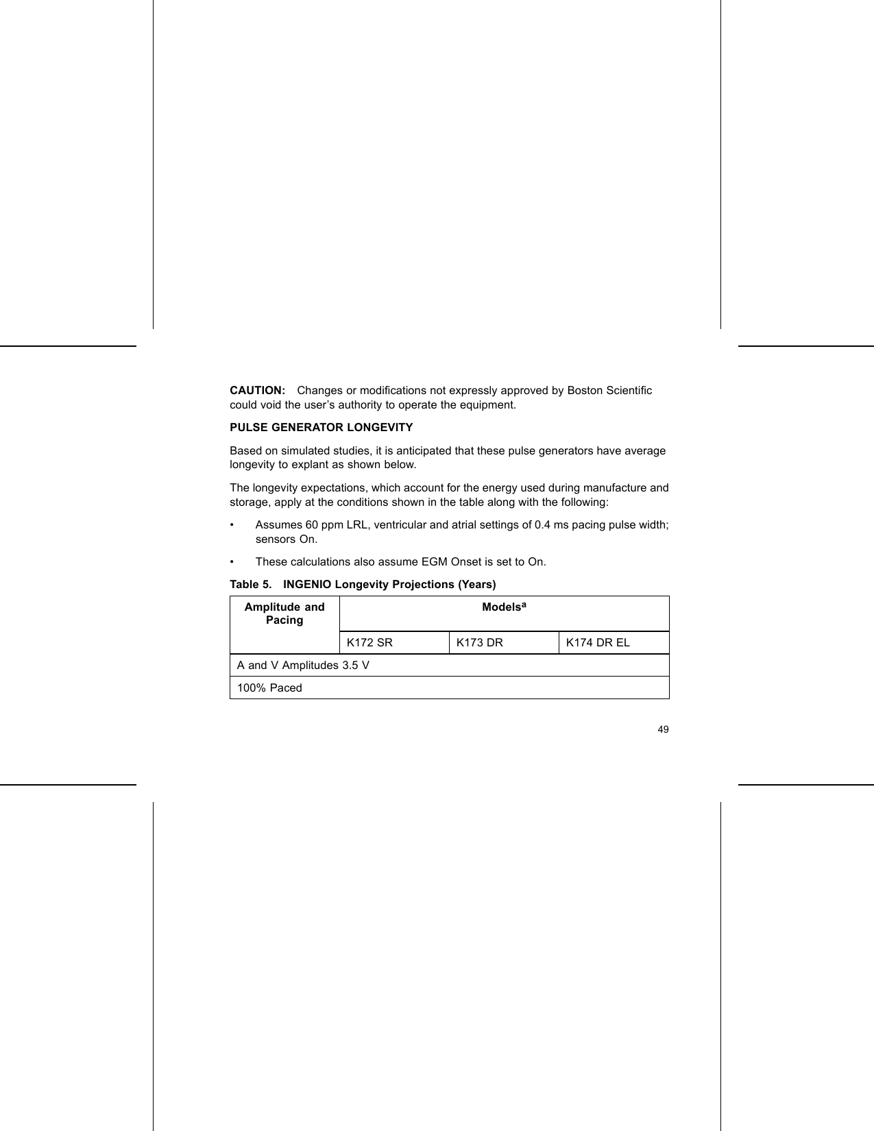
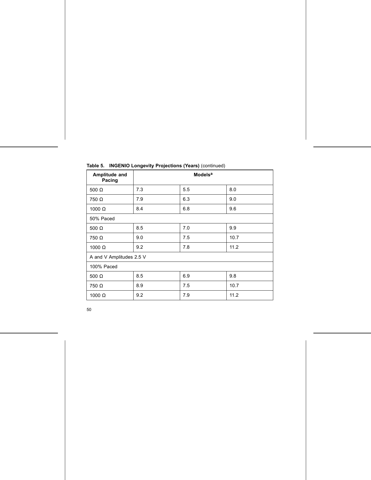
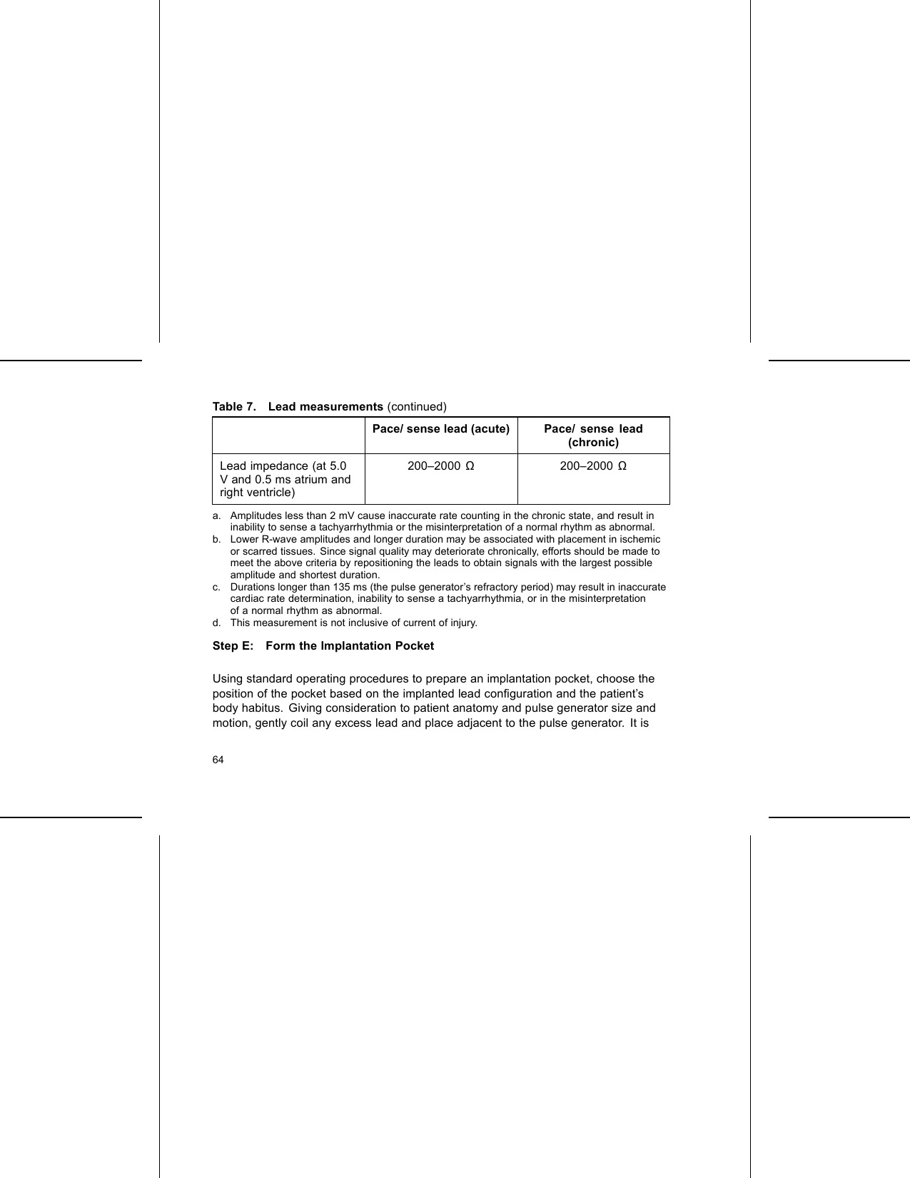
![Table 5. INGENIO Longevity Projections (Years) (continued)Amplitude andPacingModelsa50% Paced500 Ω9.3 7.9 11.3750 Ω9.5 8.4 11.81000 Ω9.6 8.6 12.1a. Assumes ZIP telemetry use for 1 hour at implant and for 20 minutes during each quarterlyfollow-up.Table 6. INGENIO Longevity Projections (Years) with Right VentricularAutomatic CaptureAmplitude andPacingModelsaK172 SR K173 DR K174 DR ELAutomatic Capture On (A = 3.5 Vb, V = 1.0 V [assuming a threshold of 0.5])100% Paced51](https://usermanual.wiki/Boston-Scientific/CRMV17311/User-Guide-1632170-Page-55.png)
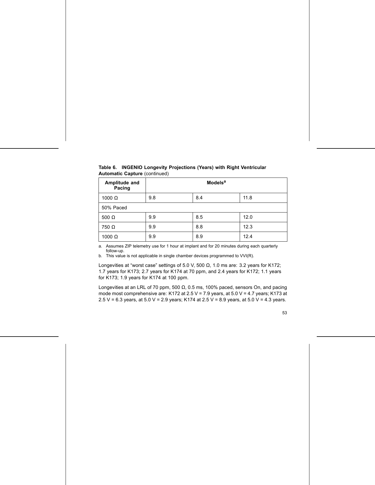
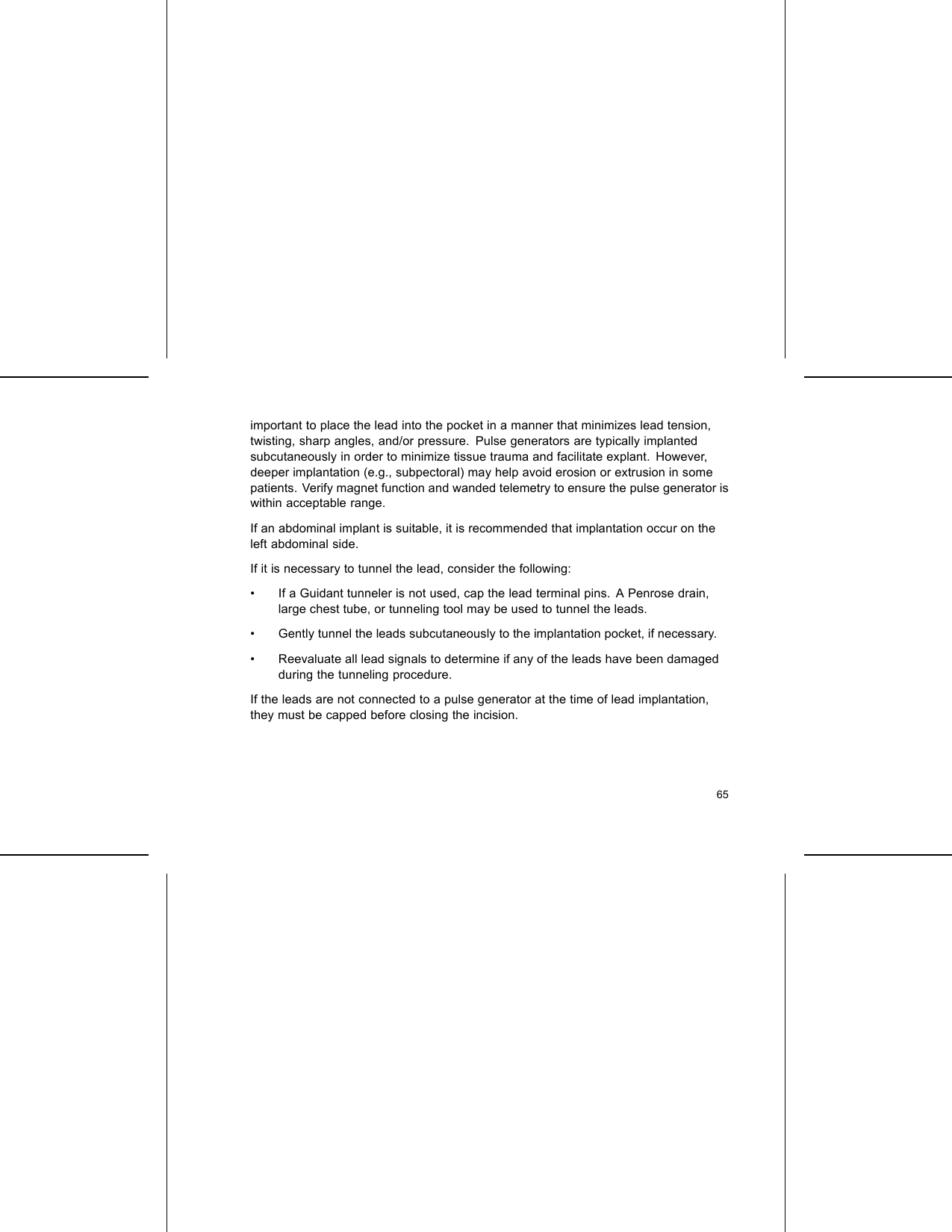
![Table 6. INGENIO Longevity Projections (Years) with Right VentricularAutomatic Capture (continued)Amplitude andPacingModelsa500 Ω9.7 6.8 9.6750 Ω9.8 7.3 10.51000 Ω9.8 7.8 11.050% Paced500 Ω9.9 7.9 11.2750 Ω9.9 8.3 11.61000 Ω9.9 8.5 11.9Automatic Capture On (A = 2.5 Vb, V = 1.0 V [assuming a threshold of 0.5])100% Paced500 Ω9.7 7.8 11.0750 Ω9.8 8.2 11.552](https://usermanual.wiki/Boston-Scientific/CRMV17311/User-Guide-1632170-Page-56.png)


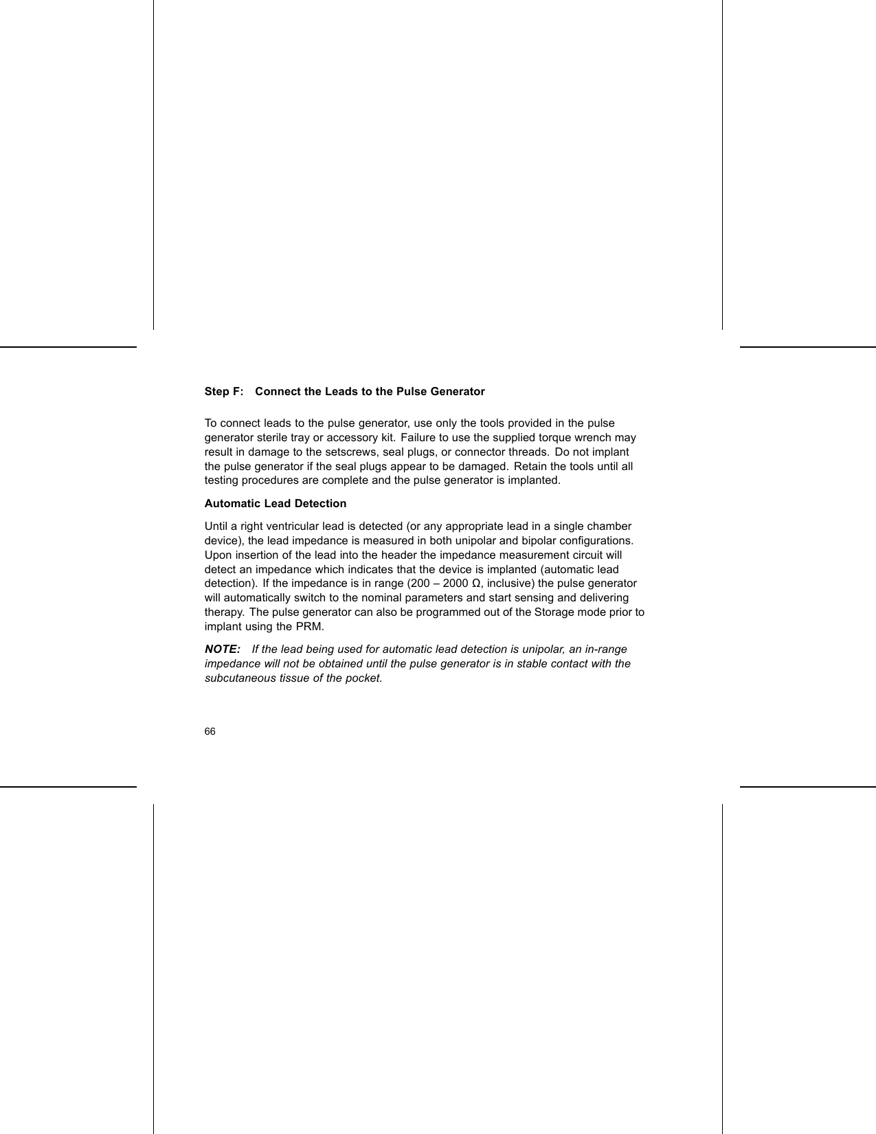
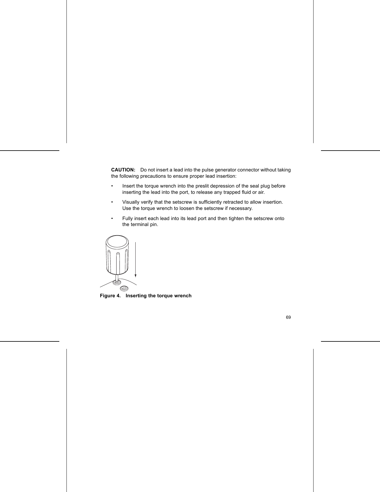
![LEAD CONNECTIONSLead connections are illustrated below.CAUTION: Prior to implantation, confirm the lead-to-pulse generator compatibility.Using incompatible leads and pulse generators can damage the connector and/orresult in potential adverse consequences, such as undersensing of cardiac activityor failure to deliver necessary therapy.CAUTION: If the Lead Configuration is programmed to Bipolar when a unipolar leadis implanted, pacing will not occur.IS-1UNI/BI[1] RA/RV [2] Suture HoleFigure 2. Lead connections and setscrew locations, RA/RV: IS158](https://usermanual.wiki/Boston-Scientific/CRMV17311/User-Guide-1632170-Page-62.png)
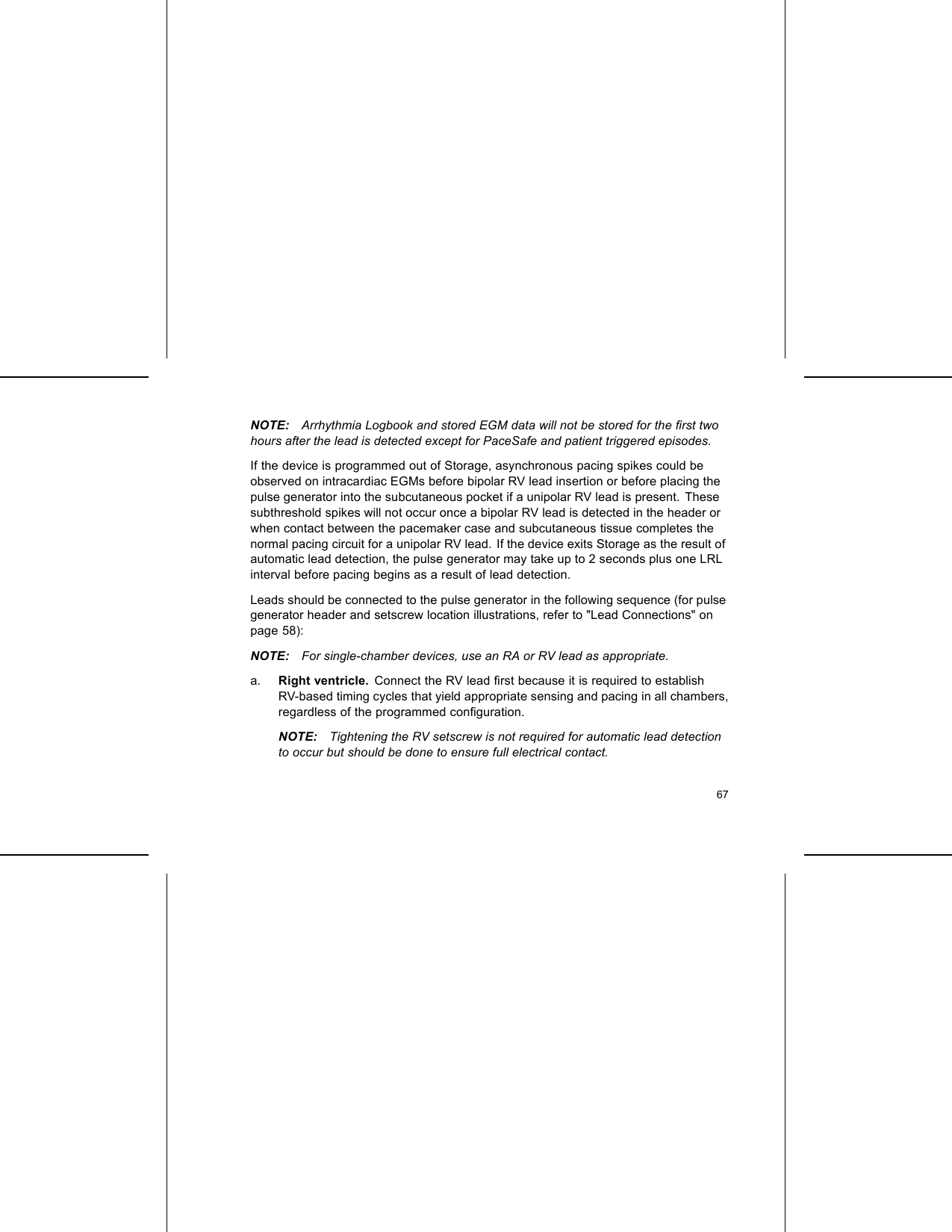
![RARVIS-1UNI/BIIS-1UNI/BI[1] RA [2] RV [3] Suture HoleFigure 3. Lead connections and setscrew locations, RA: IS-1, RV: IS-1NOTE: The pulse generator case is used as a pace electrode when the pulsegenerator has been programmed to a unipolar lead setting.IMPLANTING THE PULSE GENERATORImplant the pulse generator by performing the following steps in the sequence provided.Some patients may require pacing therapies immediately upon connecting the leadsto the pulse generator. If modifications to the nominal settings are needed, considerprogramming the pulse generator before or in parallel with implanting the lead systemand forming the implantation pocket.59](https://usermanual.wiki/Boston-Scientific/CRMV17311/User-Guide-1632170-Page-63.png)


![20°–30°[1] Clockwise rotation to free setscrews stuck in the retracted position [2]Counterclockwise rotation to free setscrews stuck in the extended positionFigure 5. Rotating the torque wrench to loosen a stuck setscrewFOLLOW UP TESTINGIt is recommended that device functions be evaluated with periodic follow-up testing bytrained personnel. Follow up guidance below will enable thorough review of deviceperformance and associated patient health status throughout the life of the device.76](https://usermanual.wiki/Boston-Scientific/CRMV17311/User-Guide-1632170-Page-80.png)