Brady IPSERIES IP Printer User Manual IP Label Printer
Brady Corporation IP Printer IP Label Printer
Brady >
Contents
- 1. Quick Start Guide
- 2. Users Manual Part 1
- 3. Users Manual Part 2
Users Manual Part 2

Printing Operation
25
Printing Operation
The printer is ready for operation when all connections are made and labels
and ribbon are loaded.
Synchronizing the Paper Feed
After the label stock has been inserted, the printer will calibrate automatically
if Brady-brand materials are used. If materials other than Brady-brand are
used, calibration is performed manually.
■Press the feed key to start the synchronization.
■Remove the blank labels produced during the synchronization.
A CAUTION
Printhead damage caused by improper handling!
• Do not touch the bottom of the printhead with
fingers or sharp objects.
• Ensure that the labels are clean.
• Ensure that the label surfaces are smooth.
Rough labels act like emery paper and reduce
the service life of the printhead.
Print with the lowest possible printhead
temperature.
Printing Operation
26
Peel-Off Mode
In Peel-off mode, the labels are automatically detached from the liner material
after printing and presented for removal. Refer to Peel-Off Mode on page 17.
Tear-Off Mode
In this mode, the labels print continuously with backing attached. After
printing, detach the label strip manually. Refer to Tear-Off Mode on page 17.
Cutting Mode
Not available in current model.
Stand-Alone Operation
Not available in current model.
NOTICE
Peel-off mode must be activated in the software.
NOTICE
A sensor prevents further printing until the
printed label has been removed from the Peel-off
position.
Control Panel
27
Control Panel
The user can control many printer operations with the control panel. These
options include:
■Starting, interrupting, continuing and cancelling print jobs (refer to Key
Functions on page 30).
■Setting print speed, interface configuration, language and time of day (refer
to Setup Menu on page 40).
■Starting test functions (refer to Test on page 32),
■Updating firmware (refer to Firmware on page 48).
Most adjustments should be performed through the software.
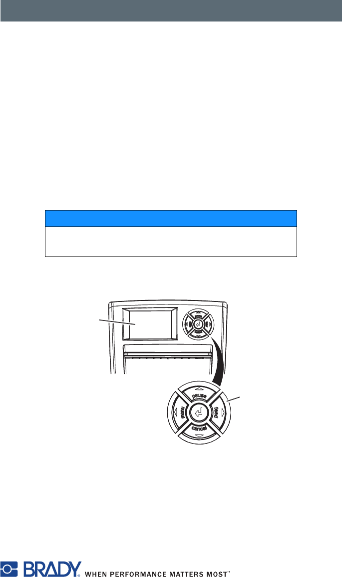
Structure of the Control Panel
Figure 12, Control Panel
The control panel consists of a graphic display (Figure 12, 1) and the
navigator pad (Figure 12, 2) with five integrated keys.
The graphic display indicates the current status of the printer, label and/or
ribbon part numbers, if Brady-brand materials are used, the print job, faults
and the printer settings in the menu.
NOTICE
Whenever possible, control print jobs through the
software.
1
2
Control Panel
28
The key functions depend on the current printer status. The key pads (for
example, menu or feed) light up white in Print mode.
Functions in Print Mode
Powersave Mode
If the printer is not used for a lengthy period, it automatically switches to
Powersave mode.
The graphic appears in the display, and key lighting is switched off.
Press any key on the navigator pad to exit Powersave mode.
Printer States
‘Ready’ state
The printer is ready and can receive data.
The display shows the text Ready and label and/or ribbon part numbers if
Brady-brand materials are used.
‘Printing label’ state
The printer is currently processing an active print job. Data can be transmitted
for a new print job. The new print job will start when the previous one has
finished.
The display shows the message Printing label and the number of the
printed label in the print job.
‘Pause’ state
The printing process has been interrupted by the operator.
The display shows the text Pause and the symbol .
‘Correctable error’ state
An error has occurred that can be rectified by the operator without interrupting
the print job. The print job can be continued after the error has been rectified.
The display shows the symbol , the type of error and the number of labels
still to be printed.

Control Panel
29
‘Irrecoverable error’ state
An error has occurred that cannot be rectified without interrupting the print
job.
The display shows the symbol , the type of error and the number of labels
still to be printed.
‘System fault’ state
If a fault occurs during the system test, the symbol and type of error are
displayed.
■Switch the printer off and then on again at the power switch.
or
■Press the cancel key.
Call Service if the error occurs persistently.
Control Panel
30
Key Functions
■The up, down, left and right arrows are used for navigating in the menu.
■The . key corresponds to the Enter key on a computer keyboard. It
confirms:
- Selection of a menu item.
- Entry of a parameter.
- Help information in the event of a fault.
Key Display State Function
menu lights Ready Ready Enter the offline menu.
feed lights Ready Ready Feed a blank label.
pause lights Ready Ready Stop printer after the end of a print
job.
Reprint the last label.
Print label Print label Interrupt print job.
Printer goes into Pause state.
Pause Pause Continue print job. Printer goes into
Print label state.
flashes Correctable
error
Continue the print job after
rectifying the fault. Printer goes into
Print label state.
cancel lights Ready Ready Delete internal memory. The last
label can no longer be reprinted.
Print label Print label Short press J cancels the current
print job.
Longer press J cancels the
current print job and deletes all
print jobs.
Pause Pause
Correctable
error
flashes Irrecoverable
error
.lights Error Call help. Concise information for
rectifying the fault is displayed.
Control Panel
31
LCD/Menu Options
Parameters for configuring the printer are found in the Setup menu on the
printer. Your printer is mainly configured via the operating panel during initial
start-up and when making major changes to the operating conditions.
Changes required for processing different print jobs should be implemented
via software settings.
You can protect the Setup menu from unauthorized access with a code
number (PIN).
Short Status
The Short status menu provides an overview of important status
information in the display of the printer.
1. Press the menu key.
2. Select Short status menu.
3. Scroll through the individual lines with the S and T keys.
4. Use the key to exit the menu.
The following configuration parameters are displayed in the Short status
menu:
Line Meaning Example
1 Printer type IP/300
2 Version number of the printer operating system
(firmware)
Firmware V1.00
3 Creation date of firmware (Aug 11 2006)
4 Version number of the system loader
(bootloader)
Bootloader V1.14
5 Creation date of the bootloader (Jul 24 2006)
6 Revision of the CPU PCB PCB Rev. 05
7 Revision of the CPU CPU Rev. 3
8 Serial number of the PCB CPU CPU
#132062821190
9 Resolution of the installed thermal printhead TPH
300dpi,1248dots
10 Previously printed paper lengths Transfer 181.44 m
11 Previously printed paper length (thermal print) Thermal 13.17 m
12 IP address of the label printer when connected to
a network
192.168.9.14

Control Panel
32
Test
Overview
The printer is equipped with different test functions providing information
about:
■The most important configuration parameters.
■The fonts available in the printer.
■The hardware components and connected peripheral devices.
■The print image quality and state of the thermal printhead.
■The function of label detection in conjunction with the optical properties of
the label medium.
■The label data sent from the computer or memory card.
The test functions are found in the Test menu:
1. Press the menu key.
2. Select Test menu.
3. Switch to the test function level with the T key.
4. Select the desired test function with the X and W keys.
5. Start the selected test function with the key.
Figure 13, Test Label

Control Panel
33
Status Print
The Status print function prints a test image containing information on
the configuration and status of the printer. The printout occurs using the heat
level and print speed specified in the Setup > Print param. menu.
NOTE: Continuous media is most suitable for this function.
1. Press the menu key.
2. Select Test > Status print menu.
3. Press the key.
You can cancel the printout with the cancel key.
The printout contains the following information:
■Device type
■Version and creation date of the firmware
■Version and creation date of the system loader (bootloader)
■Current values of selected local settings (refer to Local Settings on page 40)
■Current values of selected device settings (refer to Device List on page 35)
■Current values of selected print parameters (refer to Print Parameters on
page 43)
■Current values of selected interface parameters (refer to Interfaces on
page 46)
■Status of PIN activation (refer to Security on page 47)
■Operation time
■Number of labels printed
■Printed length with thermal transfer printing and thermal direct printing
■Current measured values of the printhead temperature and heat voltage
■Information about the label sensor
■Lines used to evaluate the print quality
Control Panel
34
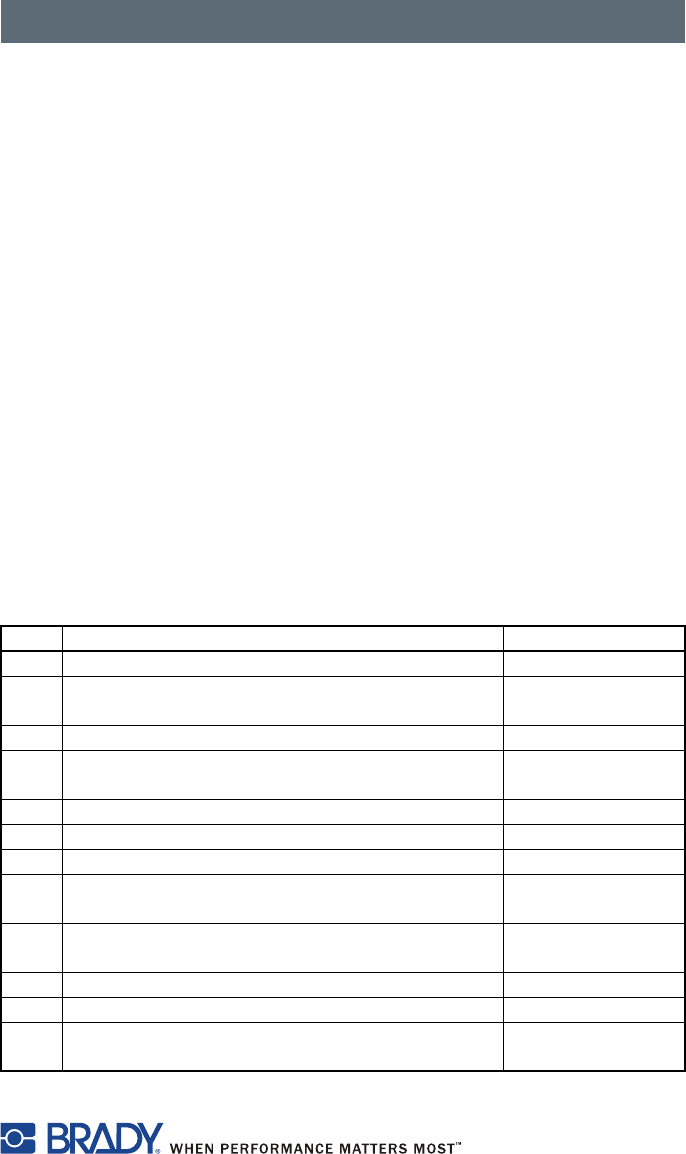
Font List
The Font list function prints the most important parameters of the fonts
available in the printer. The table contains both the original fonts and
user-loaded fonts.
NOTE: Continuous media is most suitable for this function.
1. Press the menu key.
2. Select Test > Font list menu.
3. Press the key.
You can cancel the printout with the cancel key.
Figure 14, Font List
The font parameters have the following meanings:
Column Meaning
No. ID number of the font required for programming (command T).
Name Name with which the font is saved internally.
Type Type of font generation. This provides information on the
variability of the font and is important when programming
(command T).
Description Explanations of the font: size, font family. The printout occurs in
the appropriate font.
Control Panel
35
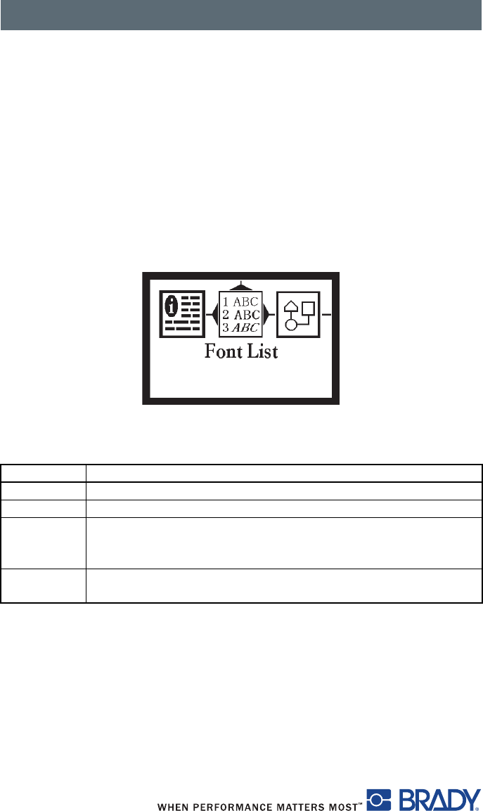
Device List
The Device list function prints out the most important information on
hardware components of the printer and connected devices.
NOTE: Continuous media is most suitable for this function.
1. Press the menu key.
2. Select Test > Device list menu.
3. Press the key.
You can cancel the printout with the cancel key.
Figure 15, Device List
Name Information
CPU Type and serial number of the CPU PCB
Revision of CPU PCB and FPGA
TPH Resolution and heating point number of the installed thermal
printhead.
I/F [x] Type of interfaces installed
x: Number of interface
Control Panel
36
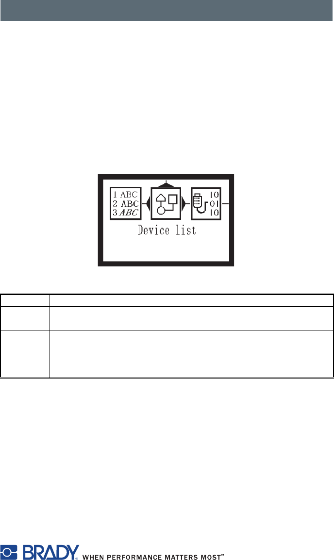
ASCII Dump Mode
ASCII Dump Mode offers the option of checking incoming control sequences
at the interface when working with direct programming. The incoming
commands at the printer are printed out as text. In addition, a corresponding
error message is printed out immediately after an error occurs.
The printout is started after four lines have been received.
NOTE: Continuous media is most suitable for this function.
NOTE: You can adjust the width of the printout down to 2 inches (50 mm)
with the Width ASCII dump parameter.
1. Press the menu key.
2. Select Test > ASCII Dump Mode menu.
3. Press the key to switch to Monitor mode.
4. Use the feed key to call up the last few lines of a label description.
You can cancel the printout with the cancel key.
Figure 16, ASCII Dump Mode
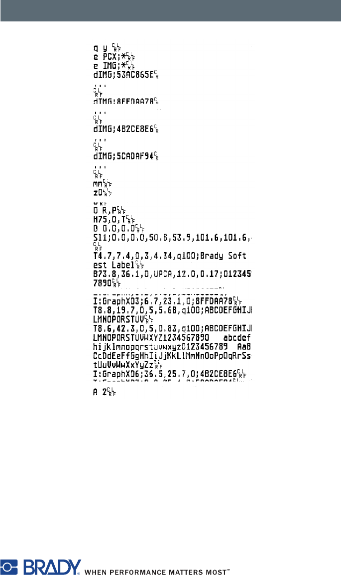
Figure 17 is an illustration of a sample ASCII Dump printout.
Control Panel
37
Figure 17, Sample ASCII Dump Mode
Control Panel
38
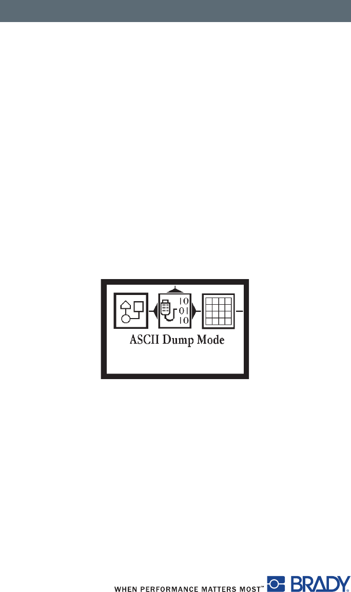
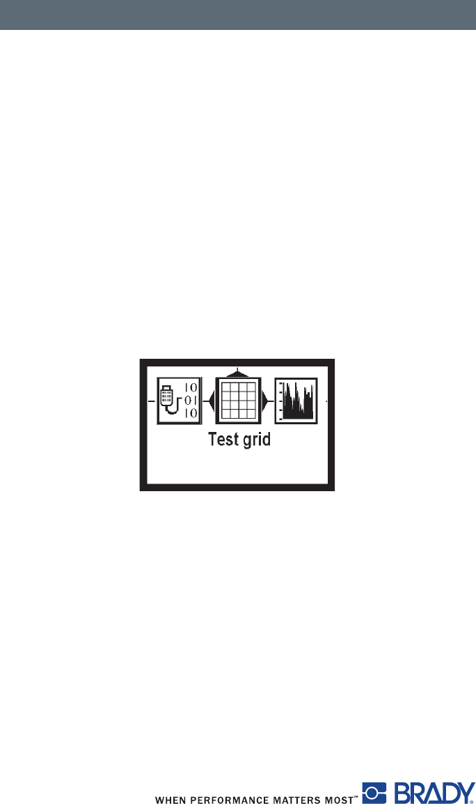
Test Grid
The Test grid function prints out the geometric pattern on a background
grid. This allows you to assess the evenness of the print quality.
NOTE: Continuous media is most suitable for this function.
1. Press the menu key.
2. Select Test > Test grid menu.
3. Press the key to start the printout.
4. Use the feed key to call up the last few lines of a label description.
You can cancel the printout with the cancel key.
The geometric pattern is printed every five seconds once the Test grid
function is started. You can adjust the printer during the pauses between the
printouts.
You can cancel the printout with the cancel key.
Figure 18, Example Test Grid
Control Panel
39
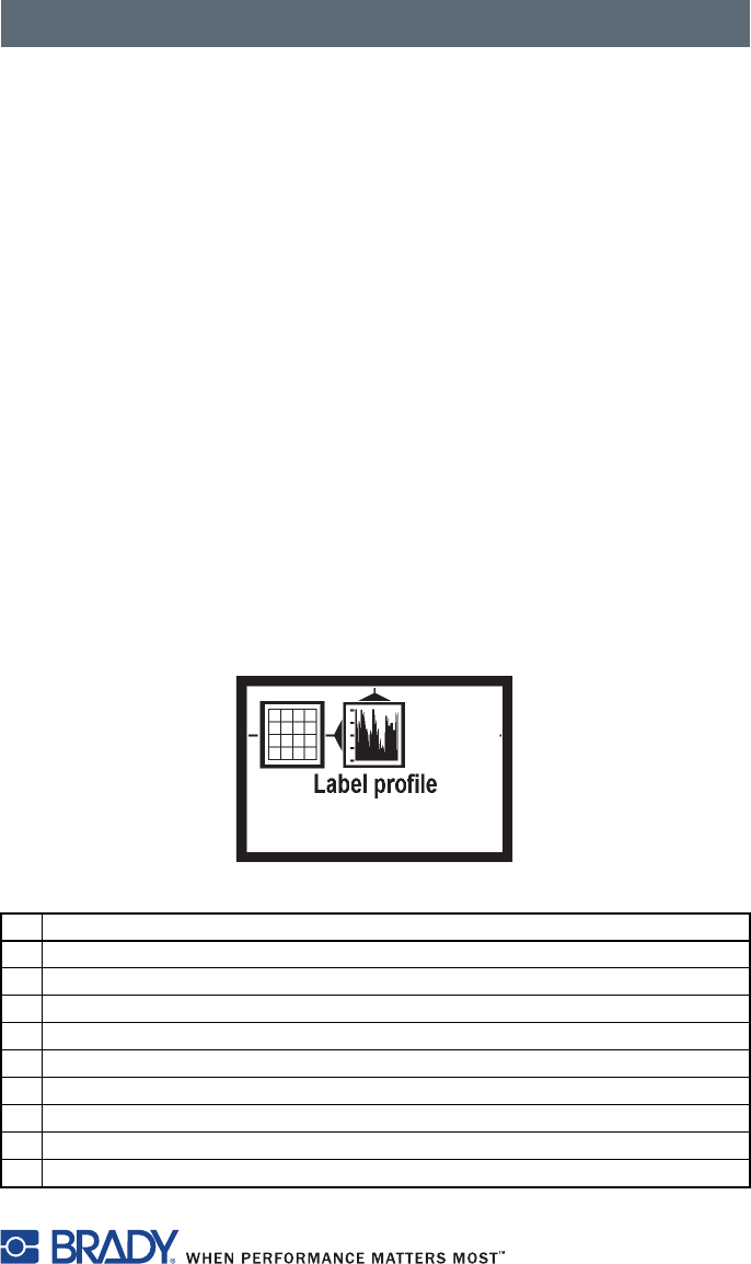
Label Profile
The Label profile function carries out a longer label advance. It saves the
values measured by the label sensor here and then prints them out in two
diagrams. The printout is used to check label detection in conjunction with the
optical properties of the label medium.
NOTE: Continuous media is most suitable for this function.
1. Select the label sensor to be tested in Setup > Print param. Refer to
Print Parameters on page 43.
2. Load the label medium to be tested into the printer.
3. Press the menu key.
4. Select Test > Label profile menu.
5. Call up the last few lines of a label description with the feed key.
6. Press the ↵ key to start the printout. The printer performs a longer label
advance. The label sensor measures the transparency/reflection capacity
of the label material. The message Test print OK appears in the
display once the advance is complete.
You can cancel the printout with the cancel key.
Figure 19, Label Profile
Description
1 Direction of paper flow at which the label start was detected
2 Type of peripheral device connected
3 Information for the firmware developer
4 Width of the negative derivative in motor increments
5 Stroke between start and end of the negative derivative
6 Scale factor for the derivative diagram
7 Service information for adjusting the label sensor
8 Method of label detection (transmitted light/reflex bottom)
9 Device name and current firmware version
Control Panel
40
Setup Menu
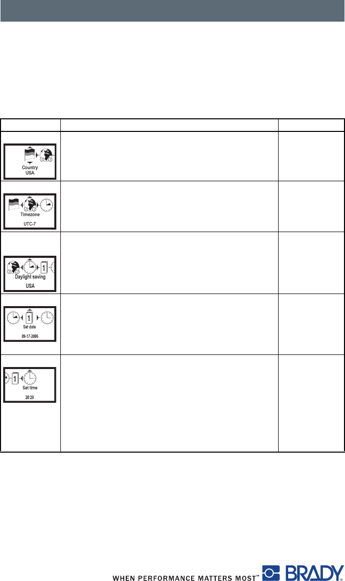
Local Settings
Press the menu key.
Select Setup > Local settings.
Parameter Meaning Default
Country Sets the display language and the
country-specific date and time formats.
USA
Timezone Adapts the time display on the printer to the time
zone in relation to UTC (Universal Time
Coordinated).
UTC
Daylight
saving
Selects daylight savings time applicable for the
region. The time changes automatically when
daylight savings time begins and ends.
USA
Set date Sets the system date in the format
DD.MM.YYYY (DD: day, MM: month,
YYYY: year). The print output of the date varies
depending on the format set via the country
parameter.
–
Set time Sets the system time in HH:MM:SS format.
When changing the time, ensure that the
timezone, daylight saving and set date
parameters are set correctly.
The time can also be synchronized
automatically via the internet using the Ethernet
interface. The print output of the time occurs in
the format set via the country parameter.
–
Control Panel
41
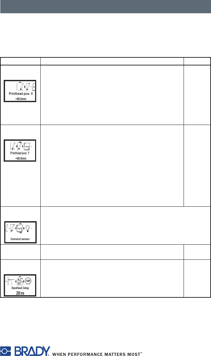
Machine Parameters
Press the menu key.
Select Setup > Machine param.
Parameter Meaning Default
Printhead
pos. X
Shifting of the entire print image perpendicular to
the direction of paper flow.
The absolute shifting is limited by the margins of the
print zone. Those are determined by the width of the
printing line on the printhead.
You can also set the Printhead pos. X via
software. The offset values from the Machine
param. menu and the software are added together.
0.0 mm
Printhead
pos. Y
Shifting of the entire print image in the direction of
paper flow. With positive values, printing begins
later in the direction of paper flow.
Shifting of the print image in the direction of paper
flow also influences the peel and tear positions.
Correct the peel position and tear position
parameters by the same value in the opposite
direction.
You can also set the Printhead pos. Y via
software. The offset values from the Machine
param. menu and the software are added together.
0.0 mm
Demand
sensor
Configuration of the Peel-off parameters for devices with
Peel-off function.
> Peel
position
[BRADY: we need information about this function]
>Backfeed
delay
Delay time between removing the label from the
peel position and the backfeed of the label.
250 ms
Control Panel
42
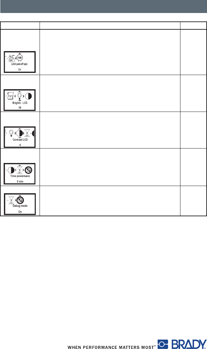
> Limit
peel-off
spd.
Limitation of the print speed in the Peel-off mode to
100 mm/s.
On
Brightn.
LCD
Brightness of the LCD display from 1 to 10. 10
Contrast
LCD
Contrast of the LCD display from 4 to 8. 6
Time
Powersave
Time between the last operation and the activation
of Powersave mode.
5 min.
Debug mode Operating mode which supports the firmware
programmer when localizing errors.
Off
Parameter Meaning Default
Control Panel
43
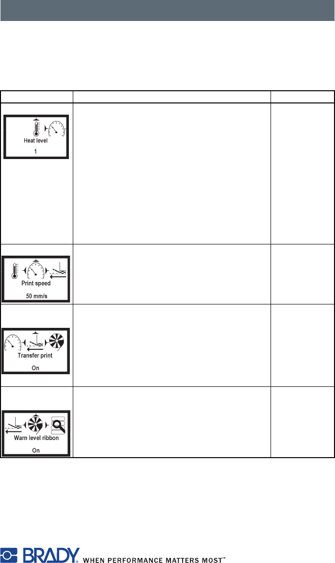
Print Parameters
Press the menu key.
Select Setup > Print param.
Parameter Meaning Default
Heat level Heating value to compensate for different
thermal behavior of printheads. Changing
this value is necessary if the printing intensity
has changed after replacing the printhead.
To adapt the printing intensity when using
different media, print speeds or printing
contents, you should change the heat level in
the software. The settings from the Print
param. menu and the software are added
together.
The heat level setting also affects the test
printouts.
0
Print speed Basic print speed setting.
You can specify the print speed for each print
job via software.
The print speed setting also affects the test
printouts.
100 mm/s
Transfer
print
On for thermal transfer printing: Sensor for
monitoring the transfer ribbon is activated.
Off for thermal direct printing: Sensor for
monitoring the transfer ribbon is not
activated.
You can overwrite the setting for each print
job via software.
On
Warn level
ribbon
Warning sent via the Ethernet interface by
way of an SNMP message or e-mail sent
when the remaining diameter of the ribbon
supply roll undershoots the set value
1.2–3 inches (32–74 mm).
Off
Control Panel
44
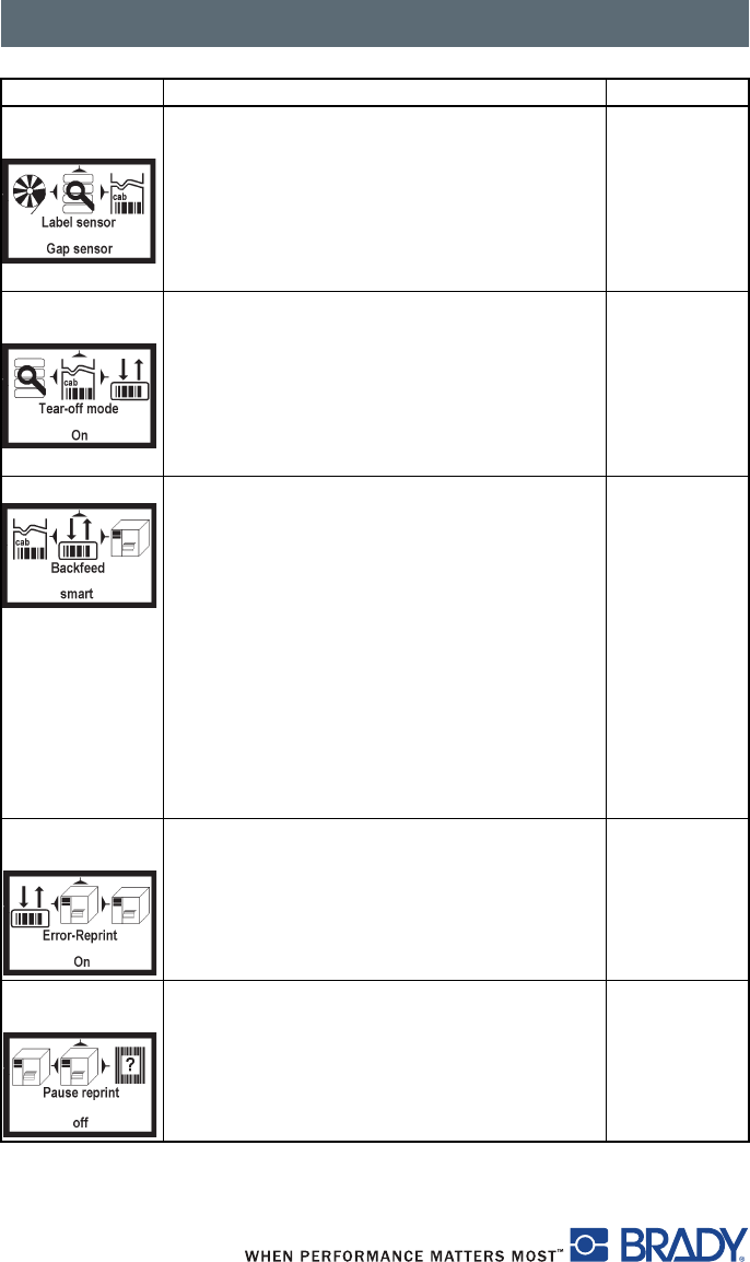
Label
sensor
Method for detecting the starting end of the
label.
Gap sensor: Detection using changes in
the transparency between the label and label
gap.
Bottom-Reflect: Detection using reflex
marks on the bottom of the medium.
Gap
Sensor
Tear-off
mode
Positioning the label medium for tearing off at
the Tear-off plate.
On: Additional advancement of the label
medium which positions the label gap after
the last printed label at the dispense plate.
Off: Label advance stops once the last label
has fully passed the print line.
Off
Backfeed Method for backfeeding the label medium.
Backfeeding is necessary in the Tear-off and
Peel-off modes since a label is pushed out
past the front edge of the next label above
the print line when peeling or tearing.
always: Backfeeding occurs independently
of label contents.
smart: Backfeeding only occurs when the
next label is not yet fully prepared when
peeling or tearing the current label.
Otherwise, the second label is pushed on
and completed after removal of the first label
without backfeeding.
smart
Error-
Reprint
On: With a correctable error and
corresponding troubleshooting, the label
being printed when the error occurs is
repeated.
Off: Print job is continued with the next
label.
On
Pause
reprint
Printing another label with the information of
the previous print job by pressing the pause
key. This function can be executed until the
print buffer is cleared with the cancel key.
Off
Parameter Meaning Default
Control Panel
45
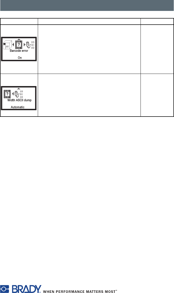
Barcode
error
On: With faulty barcode contents or size
specifications, printing is interrupted.
Off: Printing is not interrupted if an error
occurs. If barcode contents are faulty, the
printer attempts to replace the incorrect data
with valid characters (e.g. zeros). If barcode
size specifications are faulty, a gray area is
printed instead of the barcode.
On
Width ASCII
dump
Width of the printing area in the Monitor
mode test function.
With the Automatic setting, the printout of the
control sequences arriving at the printer
occurs over the maximum printing width. You
can reduce the printing area width down to
2 inches (50.8 mm).
Automatic
Parameter Meaning Default
Control Panel
46
Interfaces
Press the menu key.
Select Setup > Interfaces.
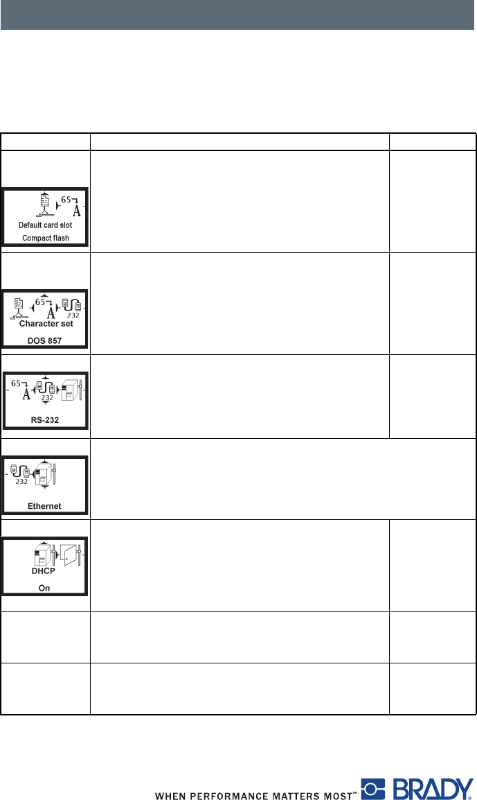
Parameter Meaning Default
Default
card slot
Selects the primary card slot. Select one of the
card slots on the back of the printer
(CompactFlash, PC Card or Ext.
CompactFlash)
Compact
Flash
Character
set
Selects the character set table.
Switching the character set via software is not
possible. You can access characters not
available in the selected character set by using
the Unicode table.
Windows
1252
RS-232 Sets the interface parameters Baud rate and
Handshake for data transfer via the serial
RS-232 interface.
Recommended settings are 115200 and
hardware handshake.
115200
Handshake
Ethernet Configures parameters for the Ethernet interface card.
You can access additional configuration parameters for the
Ethernet interface card via the printer website (refer to Setup
Menu on page 40).
> DHCP Method of issuing IP address
On: Dynamic issuing of IP address by the
DHCP server
Off: Direct issuing of the IP address by the
operator
On
> IP IP address of the label printer. Only valid with
DHCP = Off.
> Mask Subnet mask (classification and address range)
of the local network. Only valid with DHCP =
Off.
Control Panel
47
Security
By activating a PIN, you can protect the Setup menu, certain memory card
functions and the firmware update from unauthorized access.
The protected menu items are marked with the symbol and are only
accessible after the PIN is entered.
1. Press the menu key.
2. Select Setup > Security > Security menu.
3. Select On with the X and W keys.
4. Accept the setting with the key.
5. Select On with the X and W keys.
6. Select PIN with the X key.
7. Select the digit of the PIN to be changed with the X and W keys.
8. Assign the selected digit a number with the S and T keys.
9. Repeat these two steps for the remaining digits of the PIN.
10. Accept the setting with the key.
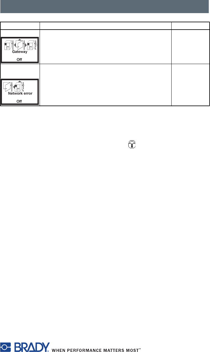
> Gateway Connection address between the local network
and other networks. The IP address of the
computer (router) on the network. The address
of the router can also be issued via DHCP.
Off
> Network
error
Printer switches to Error mode when problems
with the network connection occur.
Off
Parameter Meaning Default

Control Panel
48
Firmware
The printer firmware is saved in a Flash EPROM. You can update the
firmware using the following functions:
■Firmware upd.: Copy a firmware file from a computer connected to one
of the interfaces of the label printer. Refer to Firmware Update via Interface
on page 48.
■Firmw. fr. card: Copy a firmware file from a memory card. Refer to
Firmware Update from Memory Card on page 49.
■FTP firmware update via printer management [BRADY: is this function
available on the IP printer? If so, we need more information].
Firmware Update via Interface
1. Press the menu key.
2. Select Service > Firmware upd. menu.
3. Press the key.
4. The Firmware-Upd message appears in the display.
5. Press the key.
6. If Firmware upd. is protected via a PIN, use the S, T, X and W keys
to enter the code number and confirm with the key.
7. Open the DOS input window on the PC.
8. Configure the serial interface of the PC with the mode command. Enter
the command mode com1: baud=115200 parity=n data=8 stop=1, for
example
9. Send the firmware file (e.g. 304_6811.x2) to the printer. Enter the
command copy /b 304_6811.x2 com1:, for example.
10. A progress indicator is displayed while the firmware is being copied. OK
appears in the display once copying is successfully completed.
11. Press the key.

Control Panel
49
Firmware Update from Memory Card
1. Format CompactFlash memory card in printer [BRADY: is this function
available on the IP printer? Is it the same as the CAB manual?].
The directories "fonts," "images," "labels" and "misc" are created on the
memory card.
2. Copy the firmware file to the "misc" directory in a CompactFlash drive.
3. Insert the prepared memory card into the printer.
4. Press the menu button.
5. Select Service > Firmw. fr. card menu.
6. Press the key.
7. If the function Firmw. fr. card is protected via a PIN, use the S, T,
X and W keys to enter the code number and confirm with the key.
The names of the firmware files found on the memory card are shown in the
display.
8. If several firmware files are found on the memory card, select the desired
file with the S and T keys.
9. Press the key.
The selected firmware file is copied. A progress indicator is displayed while
the firmware is being copied. OK appears in the display once copying is
successfully completed.
10. Press the key.
Control Panel
50
Error Messages During the Firmware Update
If an error occurs during the update, one of the following error codes is shown
in the display:
NOTE: If an error occurs with a firmware update, the old firmware
version is no longer usable. Restart programming.
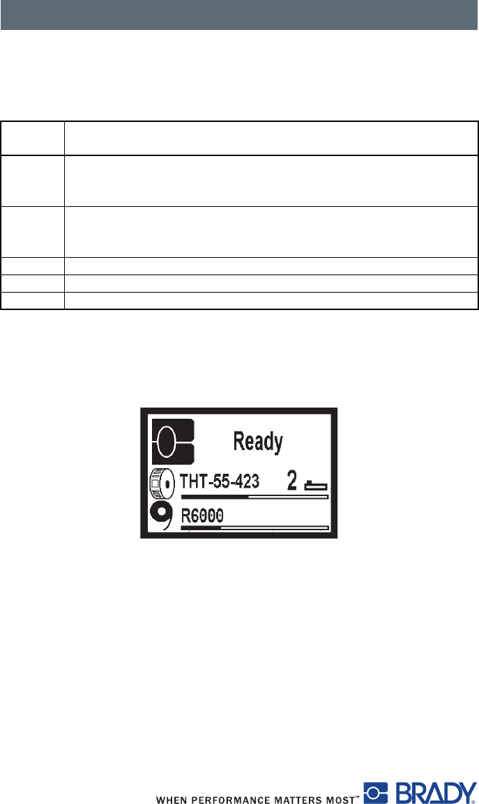
Remaining Material Display
Figure 20, Remaining Material
Error
code Meaning
CChecksum error.
/b may have been forgotten in the COPY command or the file is
defective.
HHeader error.
/b may have been forgotten in the COPY command or the file is
defective.
EEPROM could not be cleared.
VProgramming voltage is too low.
PProgramming error.
Need New Art
Control Panel
51
Adjust Screen Brightness
Calibration
[NEED INFORMATION FROM BRADY.]
Heat Settings for Print Darkness
With the use of none-standard Brady material, the heat settings in the setup
print parameters menu may vary greatly. Setting the heat excessively high can
result in not only melting the ribbon but also destroying the print head. If your
material does not have a recommended heat setting, it is recommended that
you set the heat at -20, which is the lowest possible value. At this point print a
label and evaluate it for quality. If the label is too light, change the heat setting
by one or two values in the positive direction and retry printing a label. Keep
repeating this process until you get a quality label. Once you have determined
the heat setting for this particular material, record it so that the next time you
use this material you will know where to set the heat settings.
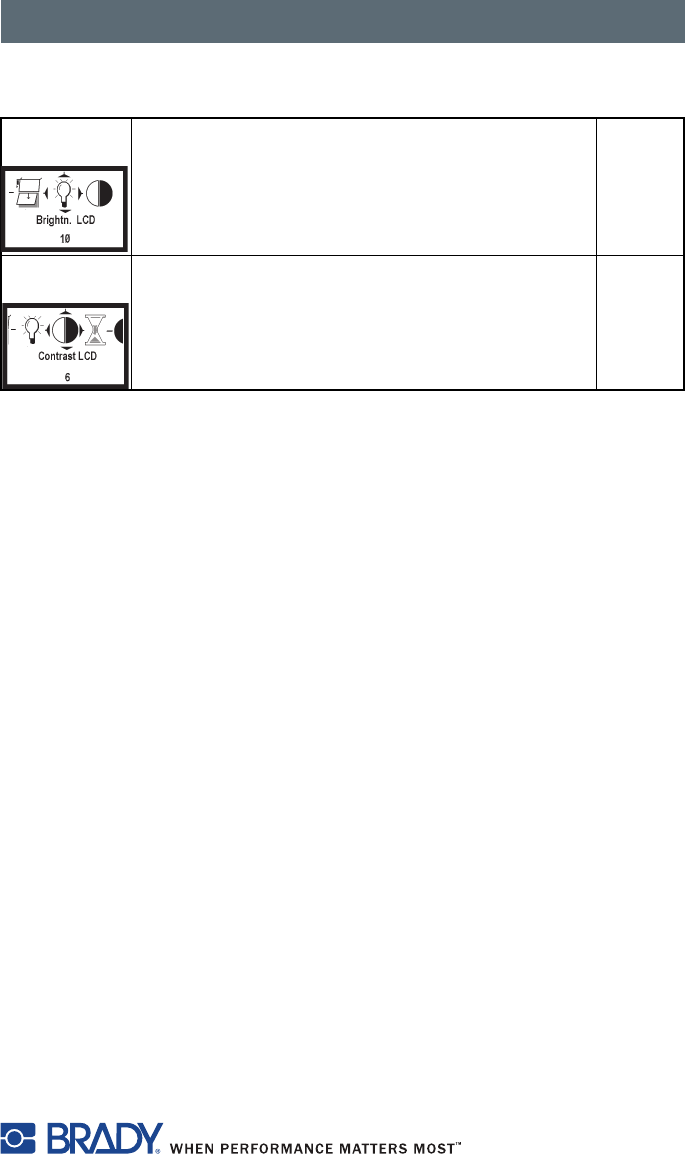
Brightn.
LCD
Adjust the LCD display brightness (1 to 10). 10
Contrast
LCD
Adjust the LCD display contrast (4 to 8). 6
Control Panel
52
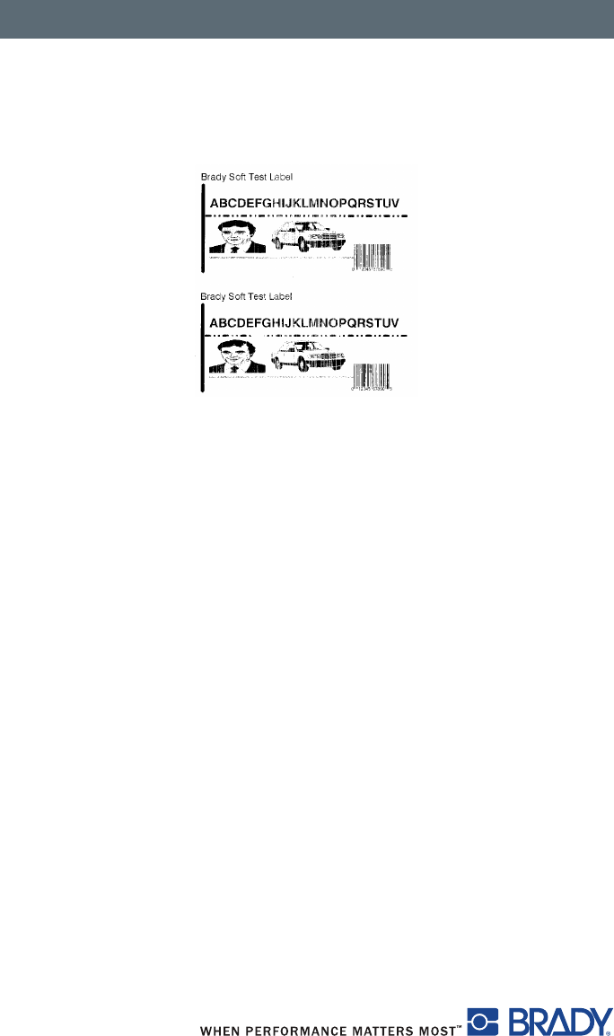
Print Sample Label
A sample label is imbedded in the firmware and can be printed through the
test menu.
Figure 21, Sample Label
Print Setting Label
[NEED INFORMATION FROM BRADY.]
Cleaning and Simple Maintenance
53
Cleaning and Simple Maintenance
It is important to clean the thermal printhead regularly. This guarantees a
consistently good printed image and will prevent premature wear of the
printhead.
Other maintenance is limited to occasional cleaning of the printer.
General Cleaning
■Remove dust and paper fluff from the print area with a soft brush, vacuum
cleaner or compressed air.
■Clean the cover of the printer with a standard cleanser.
Cleaning the Media Feed Rollers
Remove any accumulated dirt and lint from the interior of the printer using a
soft bristle brush or vacuum cleaner. Inspect this area after every four rolls of
media.
A DANGER
Electric Shock Hazard
Disconnect power to the printer before starting
any maintenance work.
NOTICE
Do not use abrasive cleaners or solvents for
cleaning external surfaces or modules. Do not use
lubricating agents of any kind.
The printer can be damaged by abrasive
cleansers. Lubricating agents can damage the
finish and mechanical parts inside the printer.
Cleaning and Simple Maintenance
54
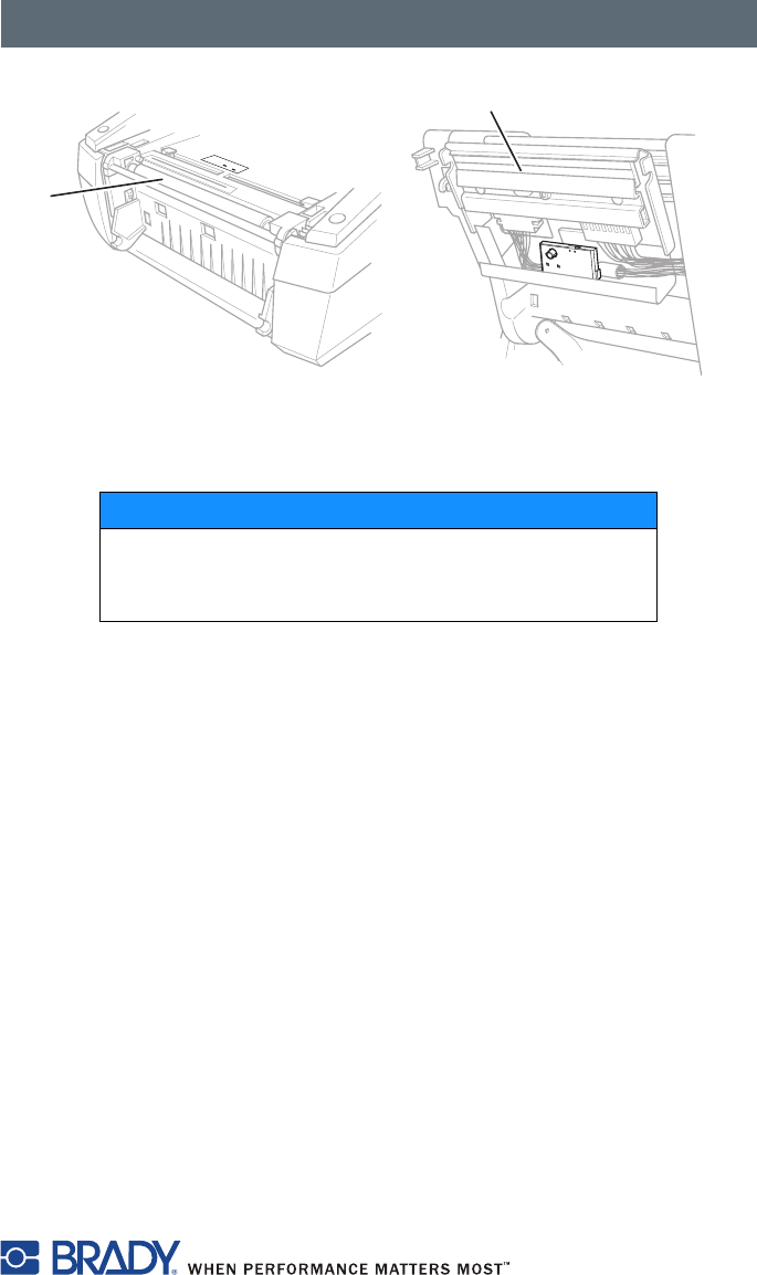
Cleaning the Printhead and Media Feed Rollers
It is important that the print head be cleaned on a regular bases. If dirt builds
up on the print head you will see vertical un-printed lines appearing in the
labels. Continuing to print under these conditions can cause the heat from the
printhead to bake this dirt into the print head and eventually destroy the
quality capabilities of your print head.
To clean the print head and/or media feed rollers:
1. Turn off the printer power.
2. Open the cover, press the release button, lower the control panel and lift
the print module up (refer to Loading the Ribbon on page 18).
3. Remove the transfer ribbon and the label stock (refer to Loading the
Material on page 18).
4. Use a cotton swab and a solvent of 90% isopropyl alcohol or Preventative
Maintenance Kit PCK-4 to carefully rub the surface of the printhead
(Figure 22, 2) and the media feed rollers (Figure 22, 1) being careful not
to scratch the printhead.
5. Allow the printhead and media feed rollers to dry for about two to three
minutes before restarting the printer.
A CAUTION
Printhead Damage
• Do not use sharp objects to clean the printhead.
• Do not touch the protective glass layer on the
printhead.
A CAUTION
Risk of injury from the hot printhead.
Ensure that the printhead has cooled down before
starting cleaning.
Cleaning and Simple Maintenance
55
Figure 22, Printhead and Media Feed Rollers
If the vertical lines still appear after cleaning the printhead, the printhead
probably has dirt baked into it and will need to be replaced.
NOTICE
Printhead replacement should always be
performed by a qualified and properly trained
technician.
20 10 010
30
40
50
1
2
Basic Troubleshooting Guide
56
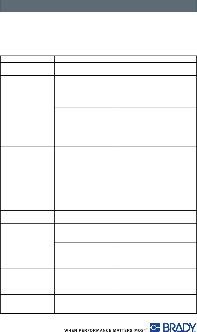
Basic Troubleshooting Guide
Troubleshooting Chart
Problem Cause Remedy
Transfer ribbon
creases.
Transfer ribbon is too
wide.
Use a transfer ribbon slightly
wider than the width of label.
Print image has
smears or voids.
Printhead is dirty. Refer to Cleaning the Printhead
and Media Feed Rollers on
page 54
Temperature is too high. Decrease temperature via the
software.
Combination of labels
and transfer ribbon is
incorrect.
Use a different type of ribbon.
Printer does not stop
after transfer ribbon
runs out.
Thermal printing is
chosen in the software.
Change to thermal transfer
printing.
Printer prints a
sequence of
characters instead of
the label format.
Printer is in ASCII Dump
mode.
Cancel the ASCII Dump mode
Printer transports
label media, but
transfer ribbon does
not move.
Transfer ribbon
incorrectly inserted.
Check and, if necessary, correct
the transfer ribbon web and the
orientation of the label.
Combination of labels
and transfer ribbon is
incorrect.
Use a different type of ribbon.
Printer only prints
every second label.
Size setting in the
software is too large.
Change the size in the software.
Vertical white lines
appear in the print
image.
Printhead is dirty. Refer to Cleaning the Printhead
and Media Feed Rollers on
page 54.
Printhead is defective
(heat element failure).
Call for service. The printhead
should always be replaced by a
qualified and properly trained
technician.
Horizontal white lines
appear in the print
image.
Printer is used with
backfeed > smart
in the Tear-off or Peel-off
mode.
Always set backfeed > in the
setup menu. Refer to Setup
Menu on page 40.
Print image is
irregular, one side is
lighter.
Printhead is dirty. Refer to Cleaning the Printhead
and Media Feed Rollers on
page 54.
Basic Troubleshooting Guide
57
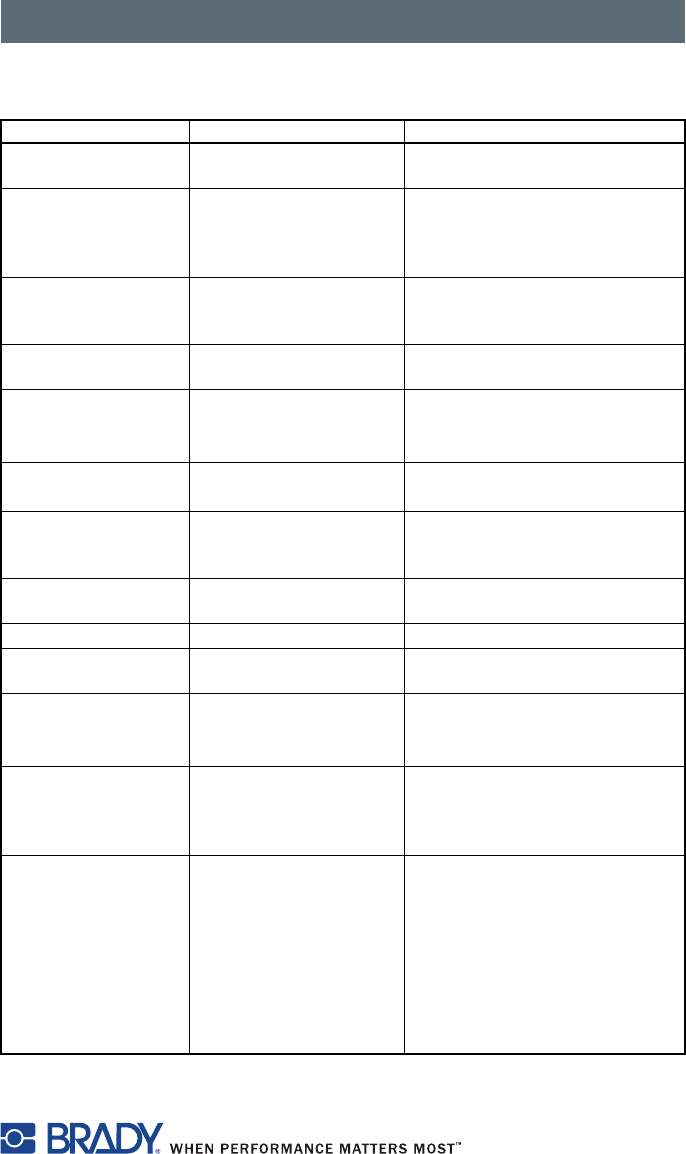
Error Messages with Corrective Actions
Error messages Cause Remedy
ADC malfunction Possible hardware issue. Recycle power to the printer. If the
error does not clear, call service.
Barcode error Barcode content is
invalid, for example
alphanumeric characters
in a numerical barcode.
Press cancel key to return printer
to Ready mode. Correct the
barcode content.
Barcode too big The barcode is too big for
the allocated area of the
label.
Press cancel key to return printer
to Ready mode. Reduce the size
of the barcode or move it.
Battery low Clock battery power is
low.
Replace the clock battery.
Buffer overflow Handshake mode is not
on.
Access the printer setup menu,
handshake mode and select
RTS/CTS.
FPGA
malfunction
Possible hardware issue. Recycle power to the printer. If the
error does not clear, call service.
Head error Printhead may need to be
replaced.
Recycle power to the printer
several times. If fault does not
clear, replace the printhead.
Head open Printhead may not be
completely closed.
Close the printhead completely
and press the pause key.
Head too hot TBD TBD
Invalid setup The Setup menu is
incorrectly configured.
Cancel the current job. Recheck
all configuration settings.
Memory overflow Handshake mode is not
on.
Access the printer setup menu,
handshake mode and select
RTS/CTS.
Multiple Tags
Read Remove
Extra Tags
Label tags read
incorrectly.
Remove and reinstall the label
spool and/or the ribbon spool. If
the error does not clear, recycle
power to the printer.
Network Error,
No Link
Ethernet is selected in the
setup menu but no
ethernet connection.
• Check that the ethernet server
is available and connected,
then recycle power to the
printer.
or
• Go to the settings menu
and turn the ethernet
connection off, then recycle
power to the printer.
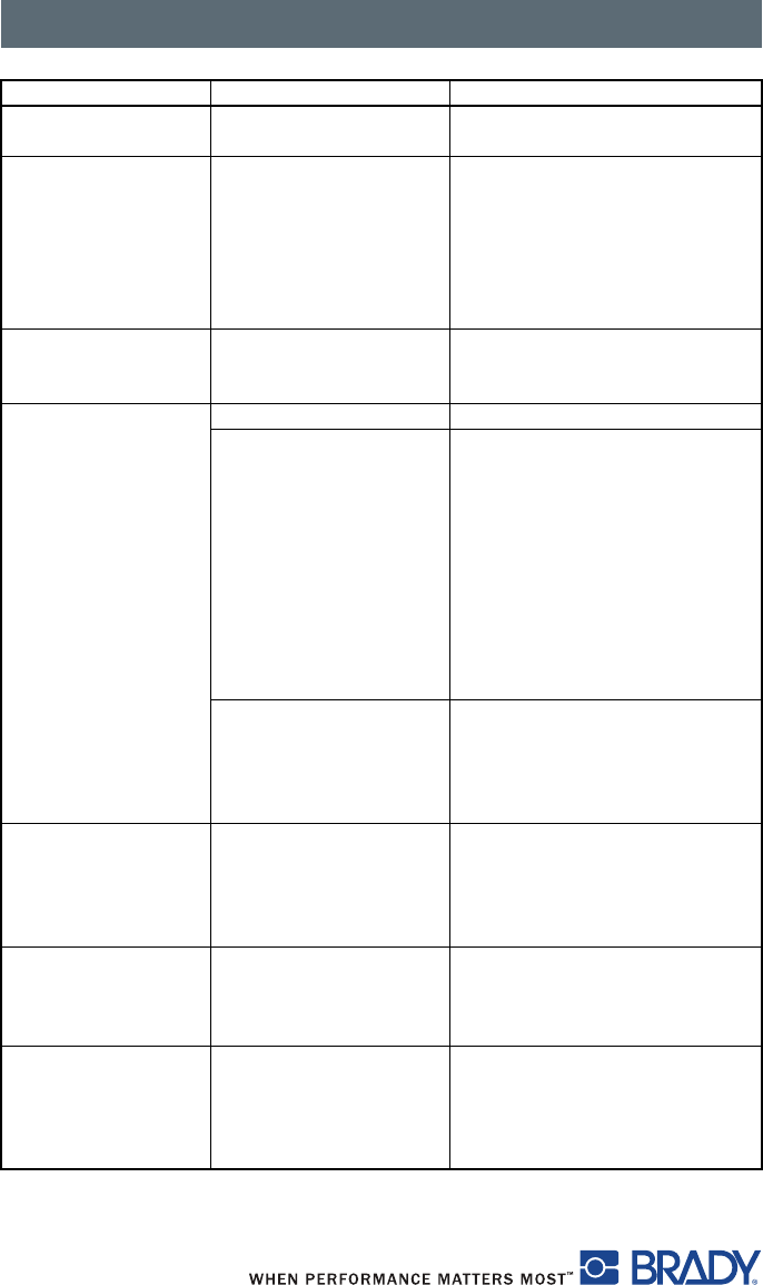
Basic Troubleshooting Guide
58
No label size The size of the label is not
defined in the software.
Check the software programming.
No SMTP server Printer is configured to
send error messages to
the server but the IP
address of the recipient
can not be found.
• Check that the IP address is
correct and if the recipient is
available.
or
• Go to the settings menu
and turn SMTP off, then recycle
power to the printer.
Out of paper Labels missing on the
label material.
Replace label material or press
the pause key to continue
printing.
Out of ribbon Out of transfer ribbon. Insert new transfer ribbon.
Transfer ribbon melted
during printing.
• Cancel the current print job.
• Change the heat level via the
software.
• Clean the printhead (refer to
Cleaning the Printhead and
Media Feed Rollers on
page 54).
• Load the transfer ribbon (refer
to Loading the Ribbon on
page 18).
• Restart the print job.
The ribbon is improperly
installed.
• Cancel the current print job.
• Reinstall the ribbon (refer to
Loading the Ribbon on
page 18).
• Restart the print job.
Protocol error Printer has received an
unknown or invalid
command from the
computer.
• Press the pause key to skip the
command.
or
•Press the cancel key to cancel
the print job.
Voltage error An incorrect voltage is
detected.
Note the details reported on this
error, then recycle power to the
printer. If the error does not clear,
call service.
Wrong revision The firmware that is
loaded or is being loaded
into the printer is not
compatible with the
hardware configuration.
Obtain the correct firmware for
this printer and load it.
Error messages Cause Remedy

Additional Support
59
Additional Support
Technical Support Numbers/Online Help
For Repair or Technical Assistance, find your regional Brady Tech Support
office by going to:
■In the Americas: www.bradyid.com
■In Europe: www.bradyeurope.com
■In Asia: www.bradycorp.com
Warranty Information
Effective December 30, 2002
All new Brady Corporation products are warranted by the manufacturer to be
free from defect in material and workmanship.
Printers and Related Hardware Products
Proof of purchase or shipment date is required to validate the warranty period.
The warranty becomes void if the equipment is modified, improperly installed
or used, damaged by accident or neglect or if any parts are improperly
installed or replaced by the user.
Products returned must be packaged in the original or comparable packing
and shipping container. In the event equipment is not so packaged, or if
shipping damage is evident, it will not be accepted for service under warranty.
Surface transportation charges for return to customers in the continental
United States is paid by Brady Corporation. Otherwise, Brady Corporation
pays CPT (carriage paid to) nearest airport; customer pays customs, duties,
taxes, and freight from airport to destination. If Brady Corporation determines
that the product returned for warranty service or replacement is not defective
as herein defined, the customer will pay all handling and transportation costs.
Printers
All printers (excluding printheads) are warranted against defect in material or
workmanship for twelve (12) months from the purchase date.
Additional Support
60
Printheads
Since printhead wear is part of normal operation, the original printhead is
covered by a limited warranty as indicated below. The warranty period begins
on the purchase date.
To qualify for this warranty, the printhead must be returned to the factory or to
an authorized service center. Customers are not required to purchase
Genuine Brady Corporation supplies (media and/or ribbons) for warranty
qualification.
However, if it is determined that the use of inappropriate or inferior supplies
has caused any defect in the printhead for which a warranty claim is made,
the user is responsible for Brady Corporation’s labor and material charges
required to repair the defect. The warranty becomes void if the printhead is
physically worn or damaged; also if it is determined that failure to follow the
preventive maintenance schedule listed in this manual has caused defect in
the thermal printhead for which a warranty claim is made.
Printhead Warranty Period
Bar code label and receipt printer printheads are warranted for a period of six
(6) months.
Related Hardware Items
Products are warranted to be free of defects in material and workmanship
from the date of purchase according to this chart:
Defective products must be returned to Brady Corporation for evaluation. In
the event of notification of defect within the warranty period, Brady
Corporation will replace the defective item provided there has not been
damage resulting from user abuse, modification, improper installation or use,
or damage in shipping or by accident or neglect.
Product Warranty Period
Accessories One (1) month
Cables One (1) month
Keyboard Display Units Six (6) months
Parts Three (3) months
BradyConnect® Print Servers Three (3) years

Additional Support
61
Supplies
Supplies are warranted to be free from defect in material and workmanship for
a period of twelve (12) months for media and twelve (12) months for ribbon
from the date of shipment by Brady Corporation. This is provided the user has
complied with storage guidelines, handling and usage of the supplies in Brady
Corporation printers.
Brady Corporation’s sole obligation under these warranties is to furnish parts
and labor for the repair or possible replacement of products found to be
defective in material or workmanship during the warranty period. Brady
Corporation may in its discretion issue a credit for any such defective products
in such amount as it deems reasonable.
Repair Services
Brady Corporation repairs are warranted against defects in material and
workmanship for 90 days from the date of repair by Brady Corporation. This
excludes printheads, which are warranted separately. This warranty does not
cover normal wear and tear.
This warranty becomes void if the item is modified, improperly installed or
used, or damaged by accident, neglect or abuse.
Warranty Exclusions & Conditions Statement
The warranties given above are the only warranties given to you. No other
warranties, express or implied, are given. Brady Corporation does not make
any implied warranty of merchantability or fitness for a particular purpose in
connection with its sale of products or services. While Brady Corporation’s
desire is to be responsive to your specific needs and questions, Brady
Corporation does not assume responsibility for any specific application to
which any products are applied, including, but not limited to, compatibility with
other equipment. All statements, technical information, or recommendations
relating to Brady Corporation products are based on tests believed to be
reliable, but do not constitute a guaranty or warranty.

Additional Support
62
Brady Corporation’s maximum liability for warranty claims is limited to the
invoice price of the product claimed defective. Brady Corporation does not
assume responsibility for delays in replacement or repair of products. Brady
Corporation shall not under any circumstances whatsoever be liable to you or
any other party for loss or profits, lost data, diminution of goodwill, or any
other special or consequential damages whatsoever with respect to any
warranty claim made by you. Specifically for software, Brady Corporation is
not liable for any incidental or consequential damages caused by abuse or
misapplication of the software or by its use in violation of the U.S. copyright
law or international treaty. No salesperson, representative, or agent of Brady
Corporation is authorized to make any guaranty, warranty, or representation
that contradicts the foregoing. Any waiver, alteration, addition, or modification
to the foregoing warranties must be in writing and signed by an executive
officer of Brady Corporation to be valid.
Repair and Replacement Parts
[NEED INFORMATION FROM BRADY.]
Product Registration
Register your Brady IP Printer online at www.bradycorp.com/register and
receive free product support and updates!


For Repair or Technical Assistance, find your regional
Brady Tech Support office by going to:
■In the Americas: www.bradyid.com
■In Europe: www.bradyeurope.com
■In Asia: www.bradycorp.com
Y#
Bar Code Label