Brooks Automation ATR60LFCAN Low Frequency RFID Reader with CAN Bus Interface User Manual ATR60LF
Brooks Automation Inc. Low Frequency RFID Reader with CAN Bus Interface ATR60LF
UserManual.wiki
>
Brooks Automation
>
ATR60LFCAN User Manual
User manual
Navigation menu
Upload a User Manual
Namespaces
Wiki Guide
HTML
PDF
Info
Views
User Manual
Discussion / Help
Navigation
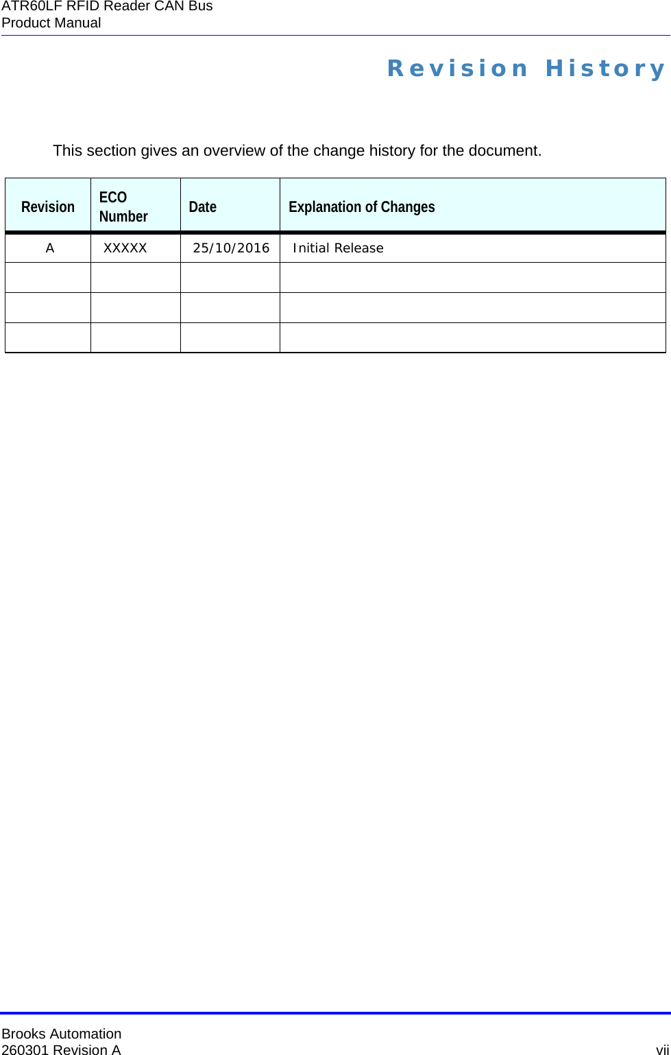


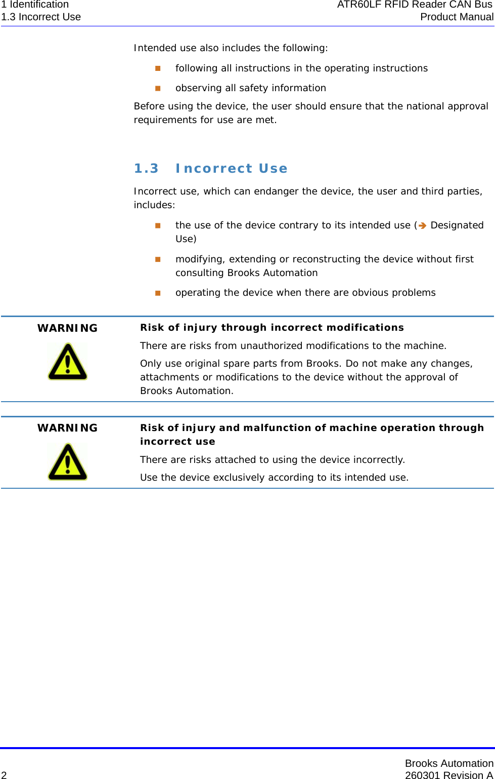
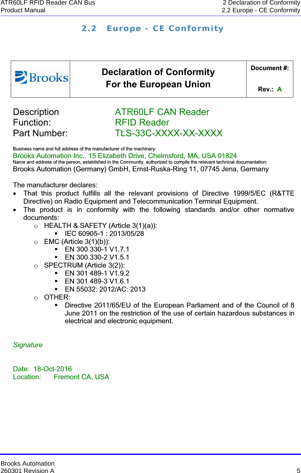
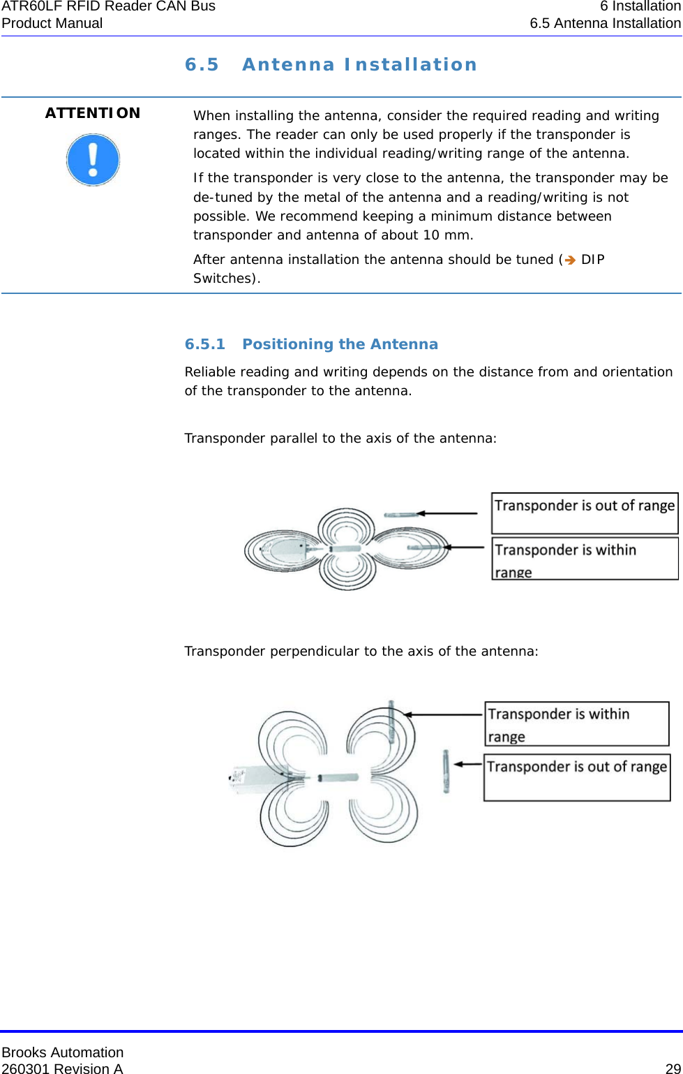

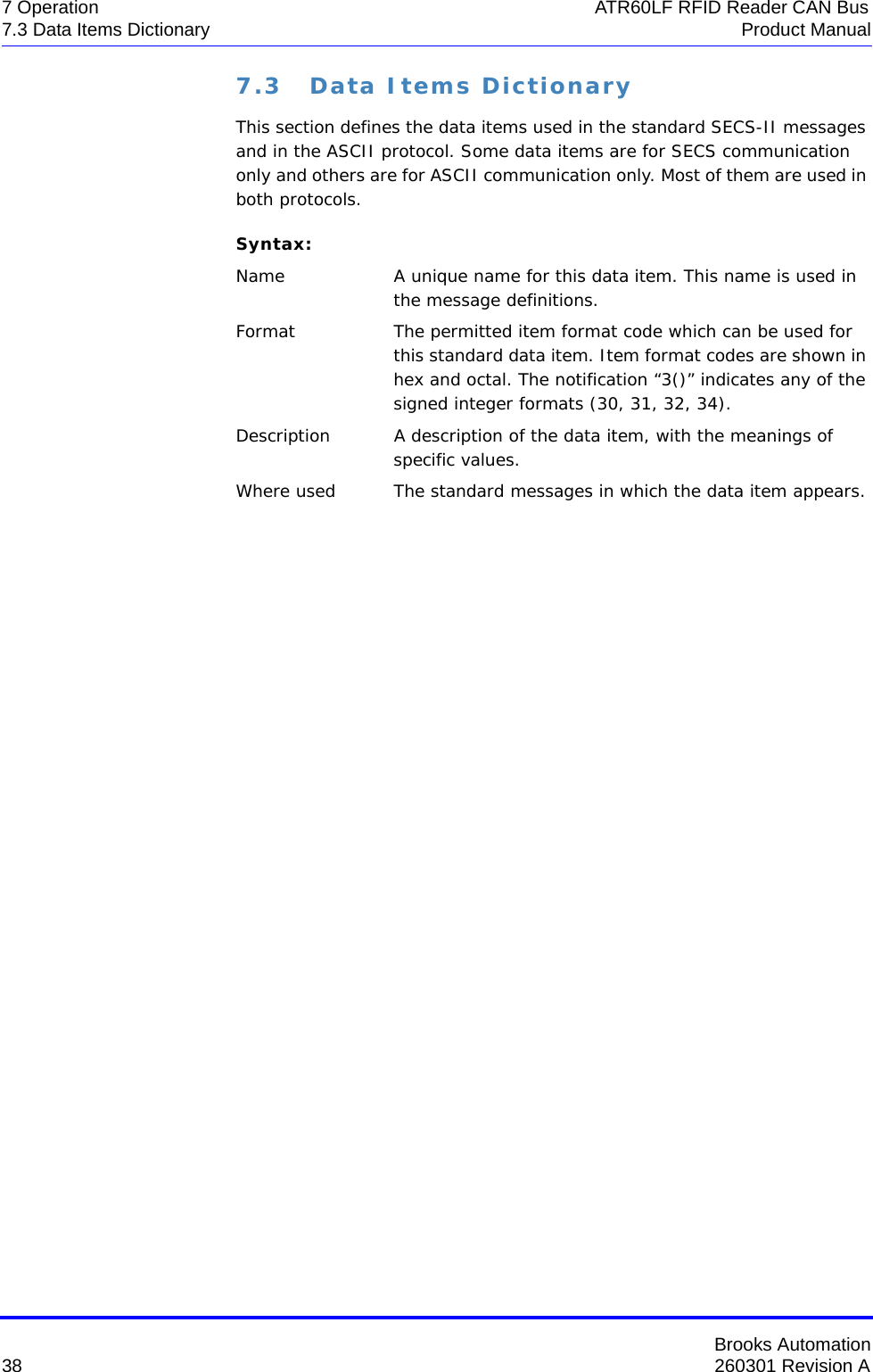
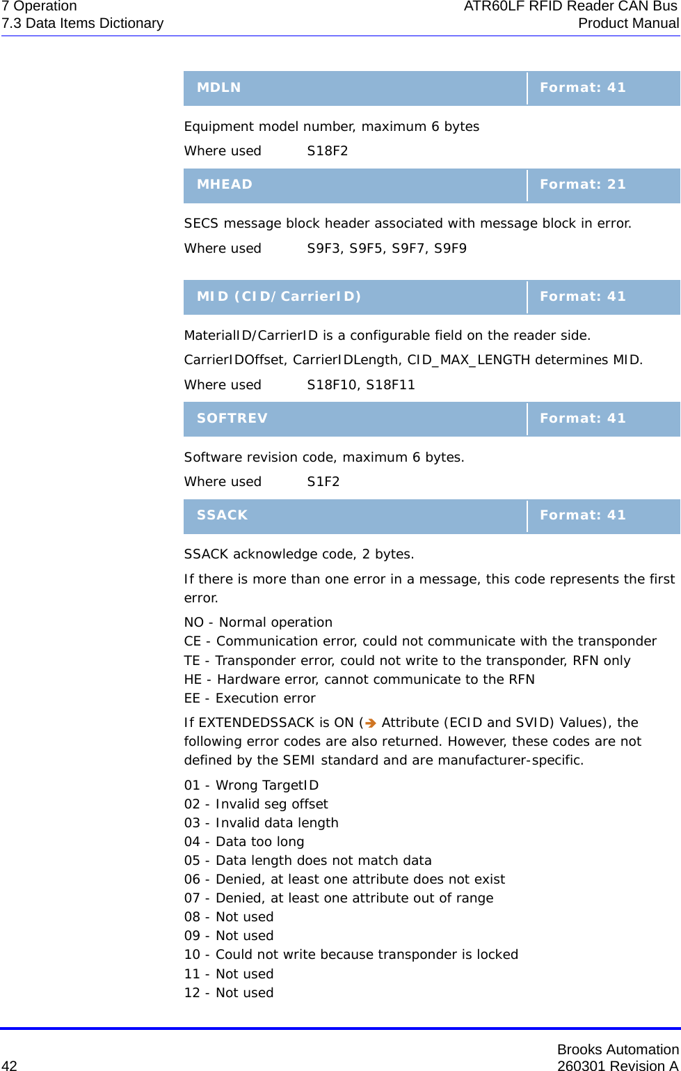
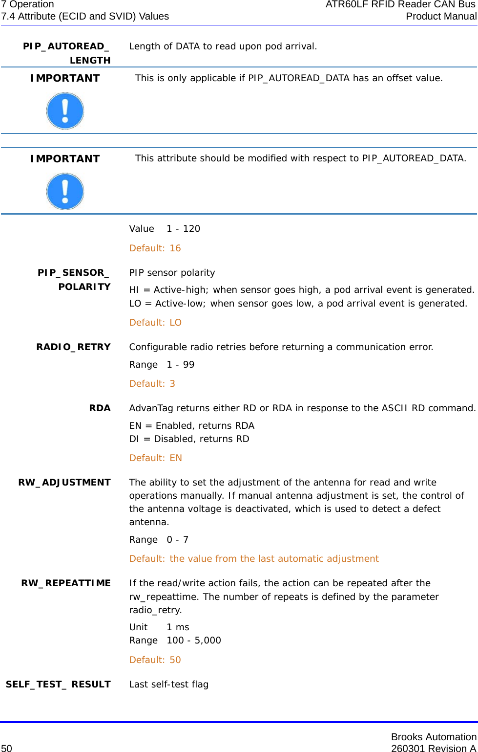
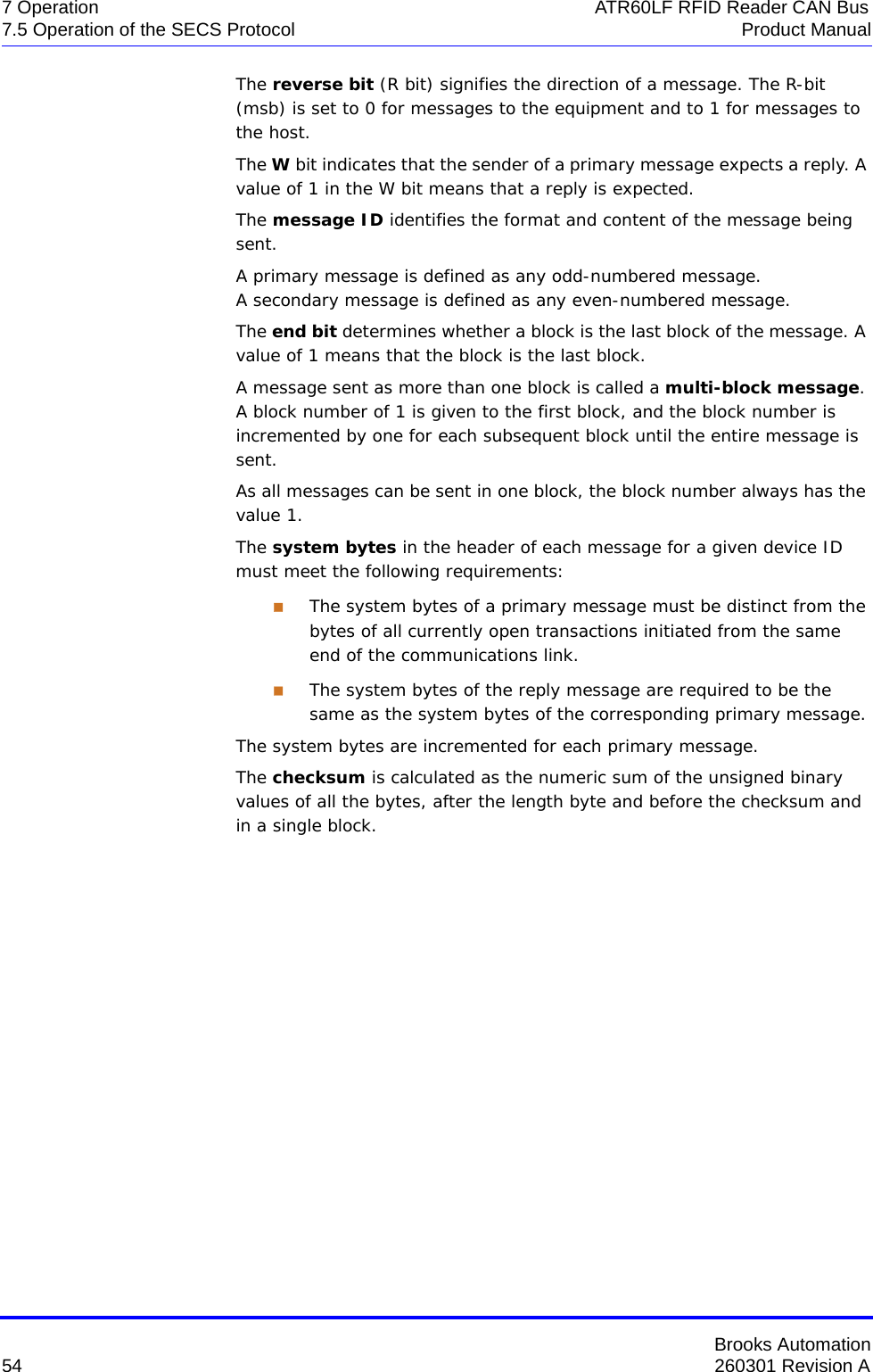
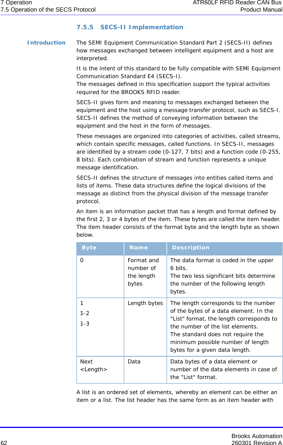
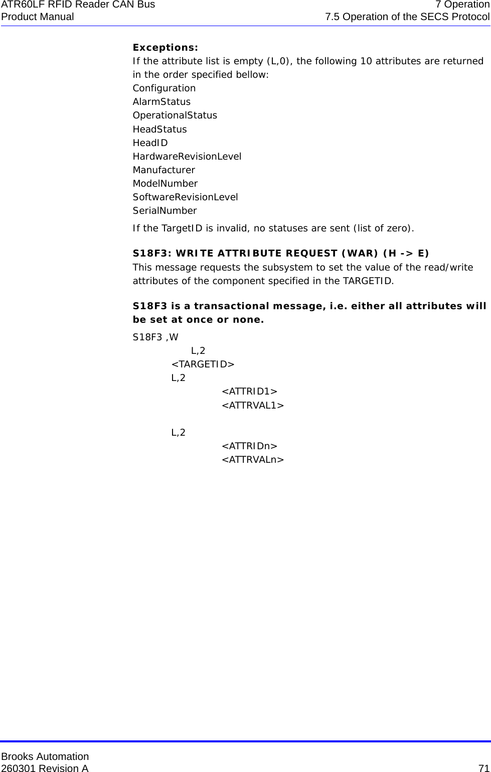
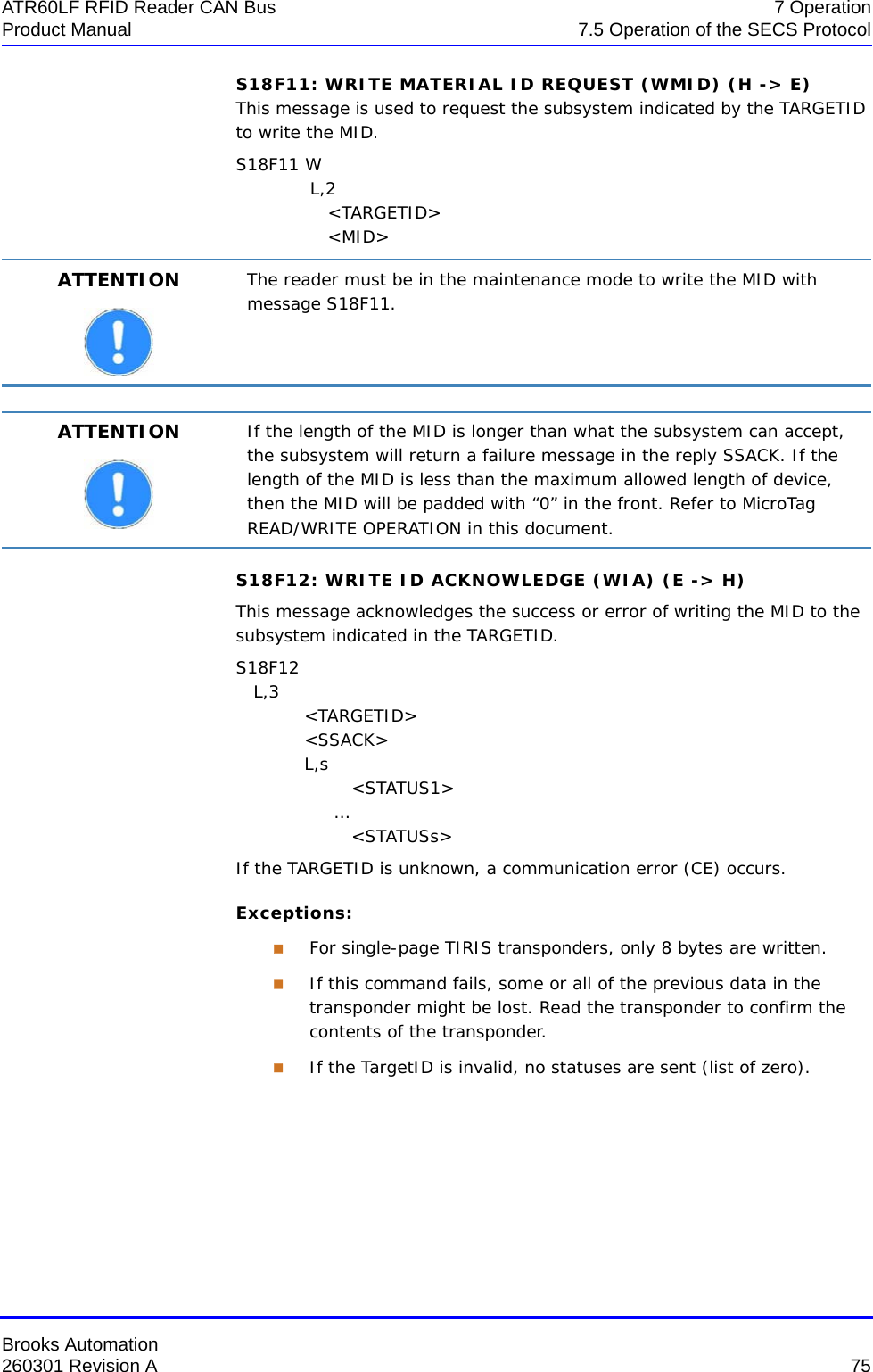
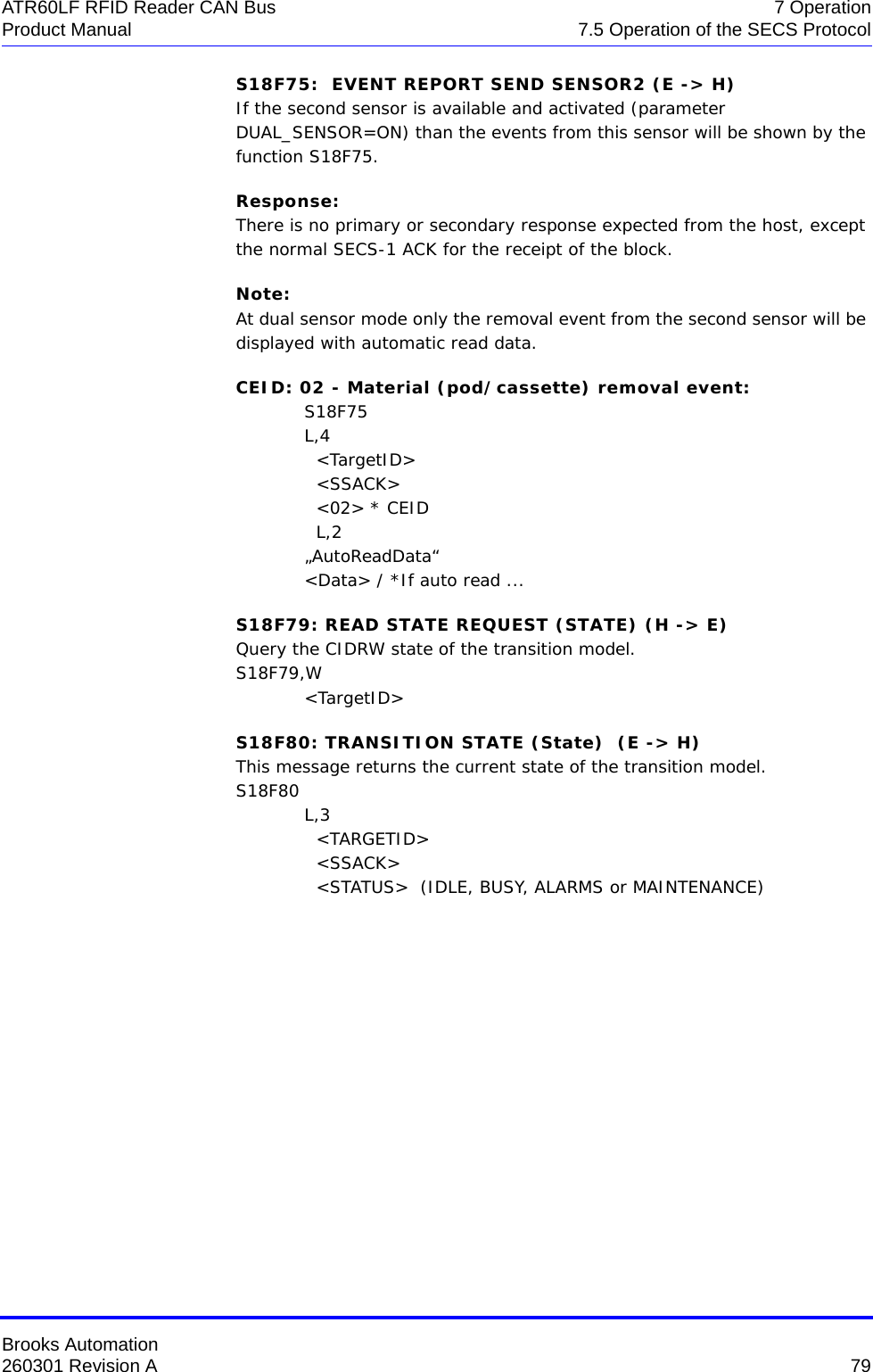
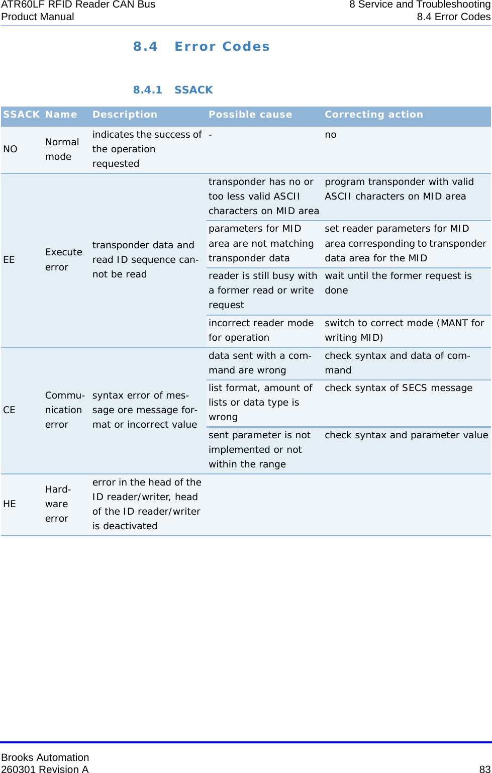
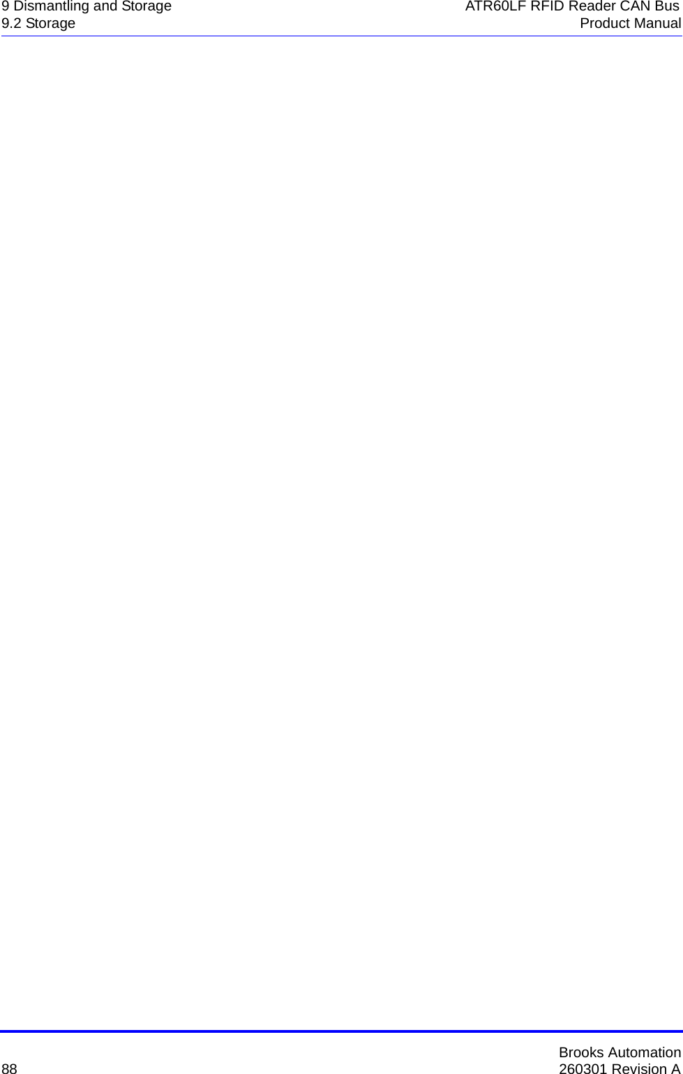
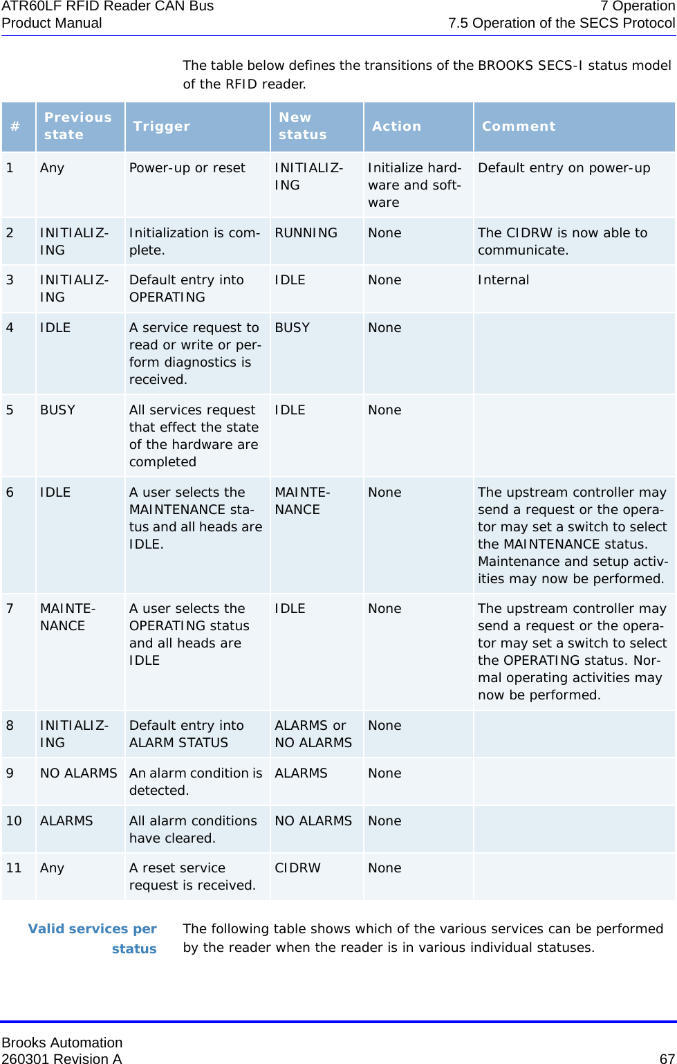
![Brooks Automation260301 Revision A 63ATR60LF RFID Reader CAN Bus 7 OperationProduct Manual 7.5 Operation of the SECS Protocolformat type 0. However, the length byte refers to the number of elements in the list rather than to the number of bytes.Data items The formats represent arrays of types: <type>[number of elements], whereby <type> is one of the following:Oct- code Hex-code FormatMeaning Example00 01 List List element with the number of the “Length” data elements<L2> <A “Hello”> <B 0x00>11 25 Boolean 1-byte Booleanfalse = 00true = 01 <Boolean1 0x00>10 21 Binary Byte sequenceof the length “Length” <B1 0x01>20 41 ASCII Printable ASCII characters <A “Hello”>31 65 I1 1-byte signed integer <I1 123>32 69 I2 2-byte signed integer <I2 -12345>34 71 I4 4-byte signed integer <I4 2147483647>30 61 I8 8-byte signed integer <I8 931372980293834>51 A5 U1 1-byte unsigned integer <U1 0>52 A9 U2 2-byte unsigned integer <U2 #empty>54 B1 U4 4-byte unsigned integer <U4 429489725>50 A1 U8 8-byte unsigned integer <U8 763468676756767>40 91 F8 8-byte floating point <F8 1.223 e204>44 81 F4 4-byte floating point <F4 -1.23 >](https://usermanual.wiki/Brooks-Automation/ATR60LFCAN/User-Guide-3210441-Page-75.png)
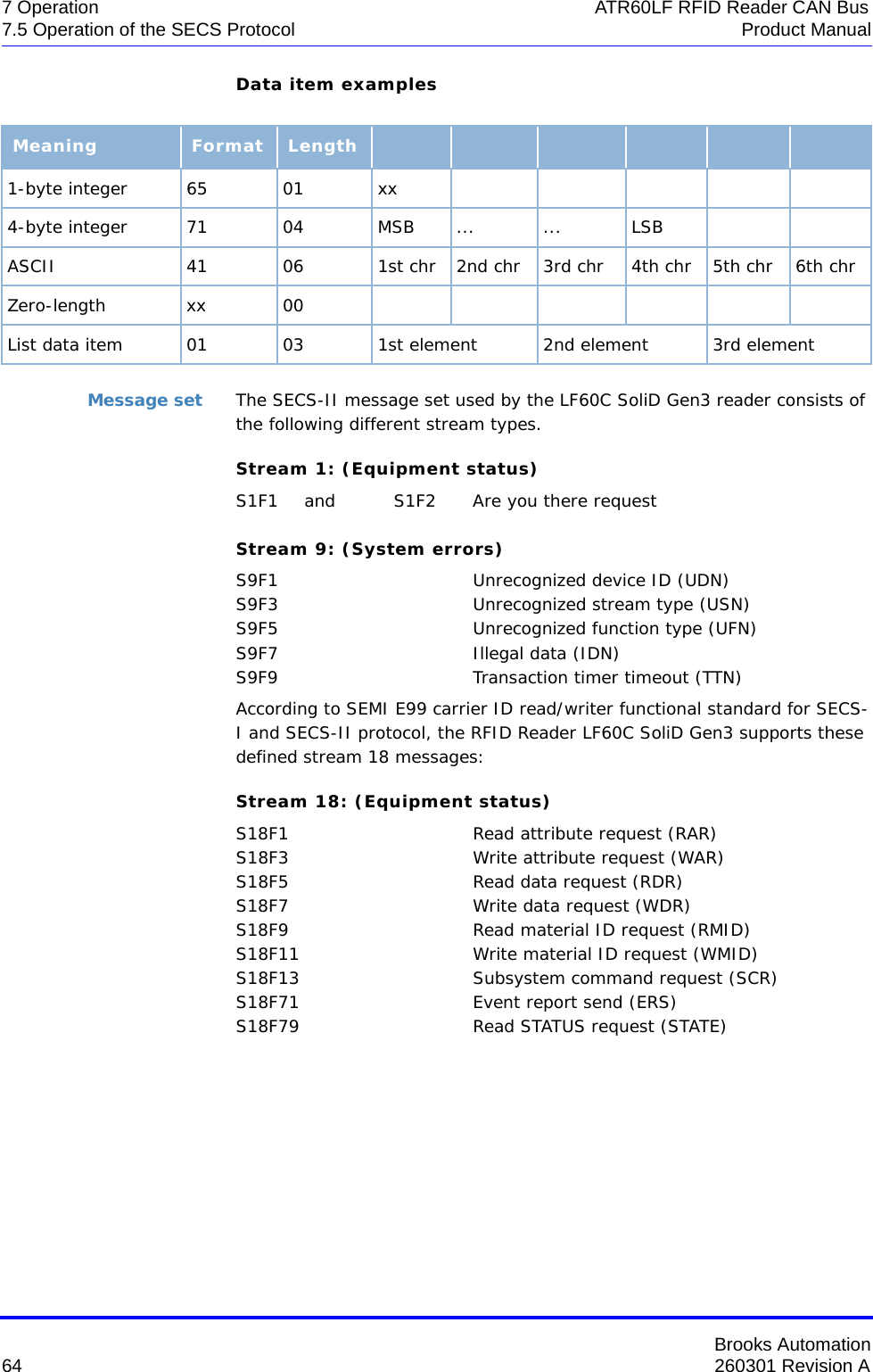
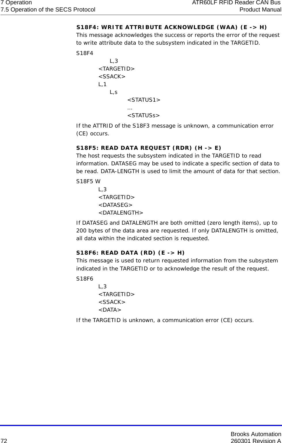
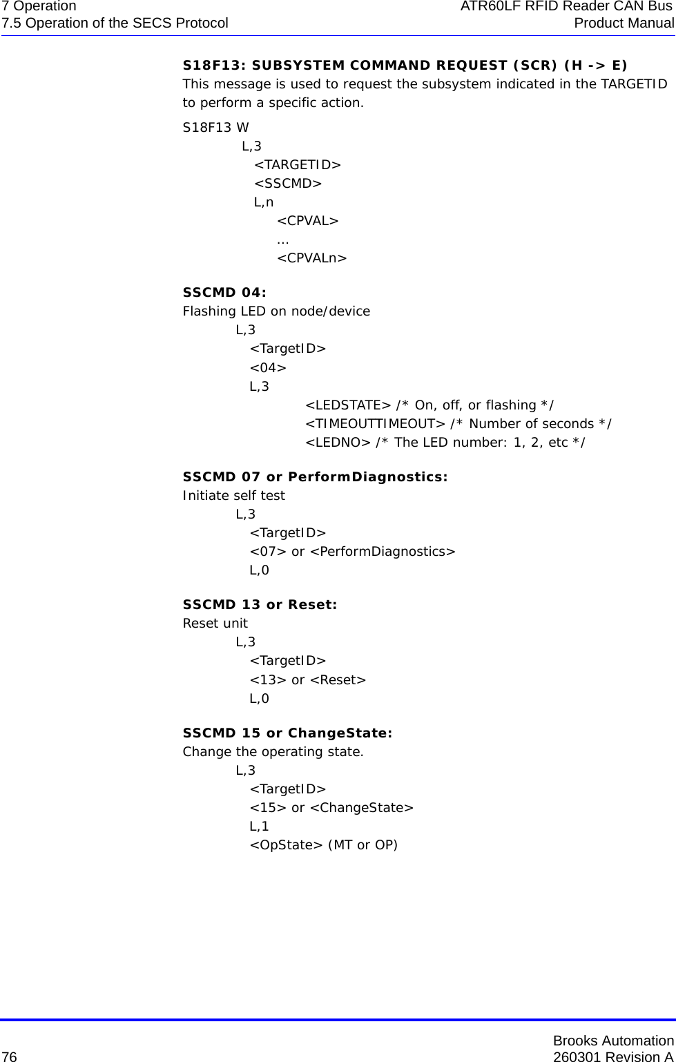
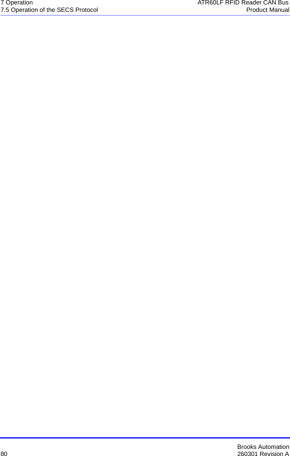
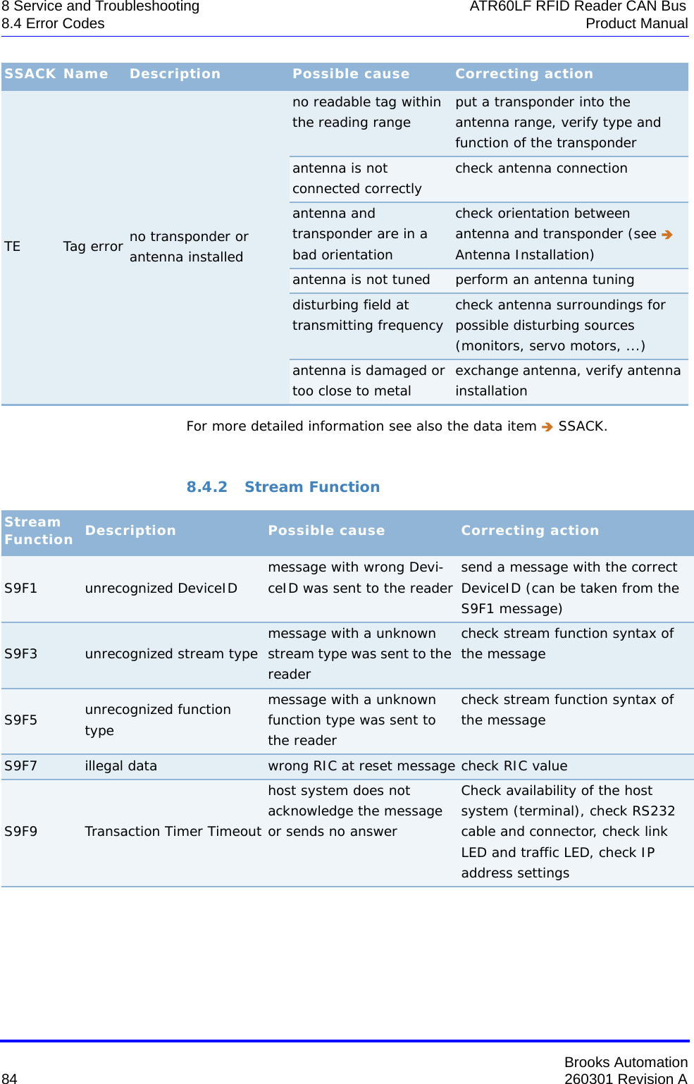
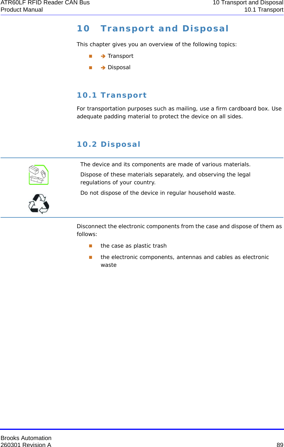
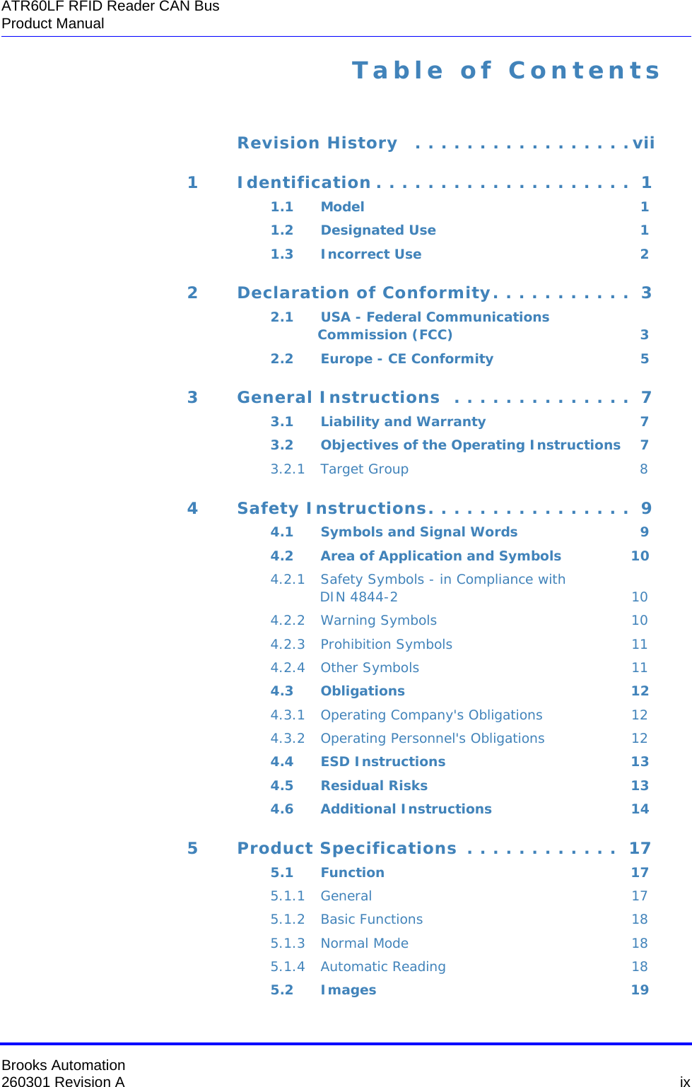
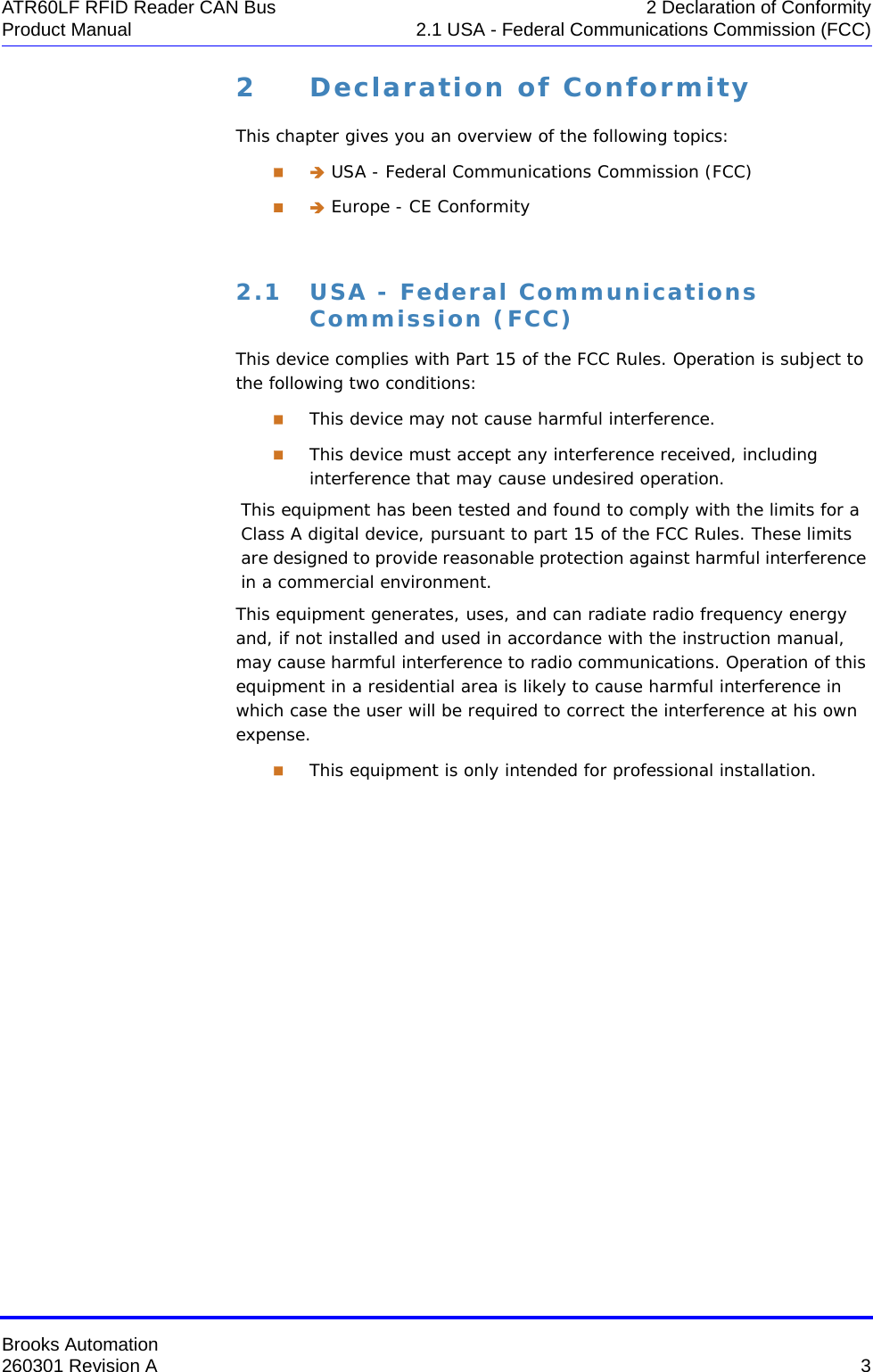
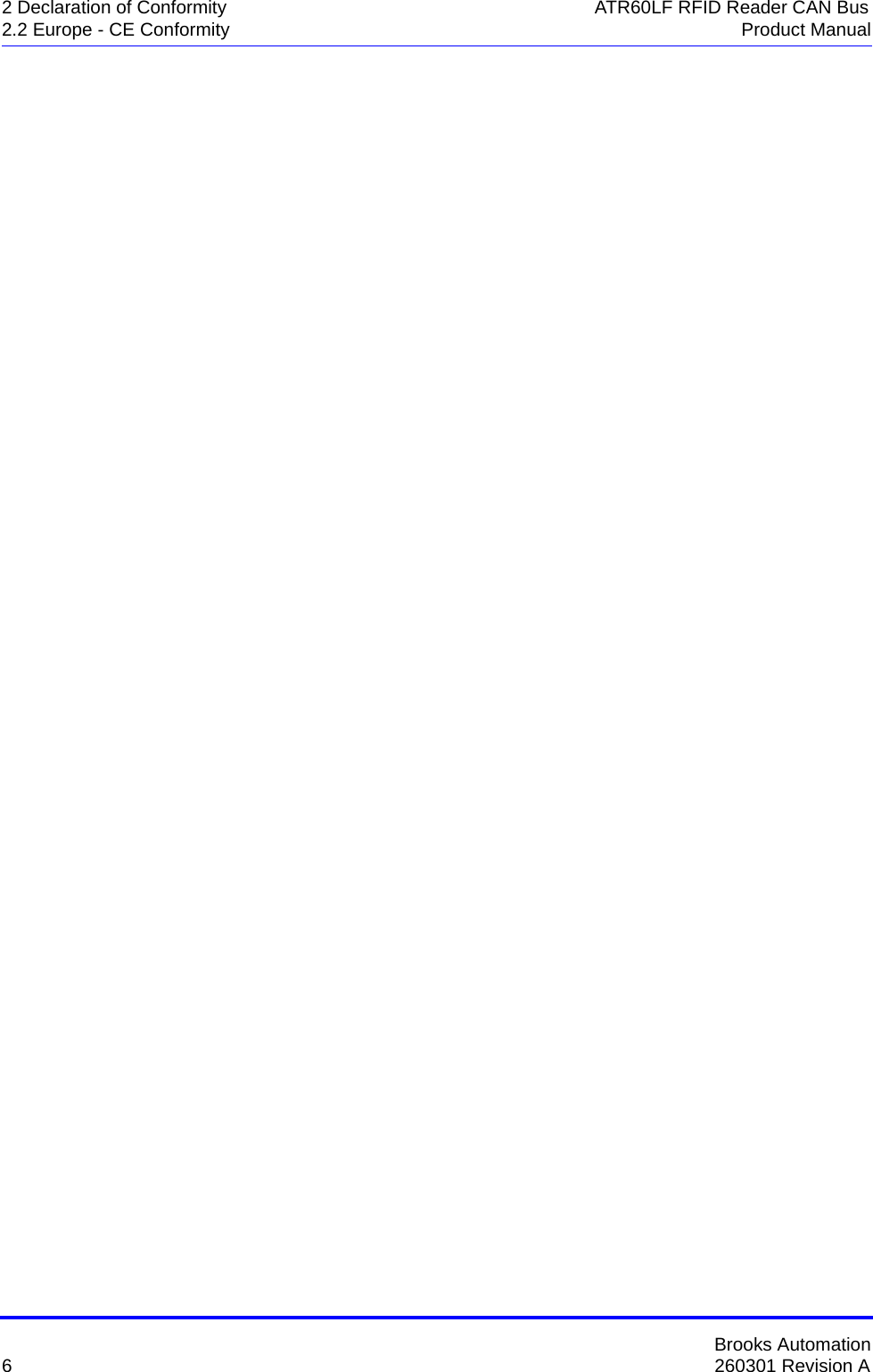
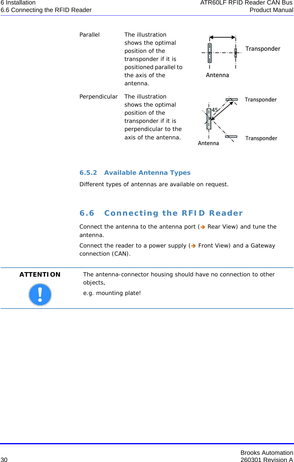
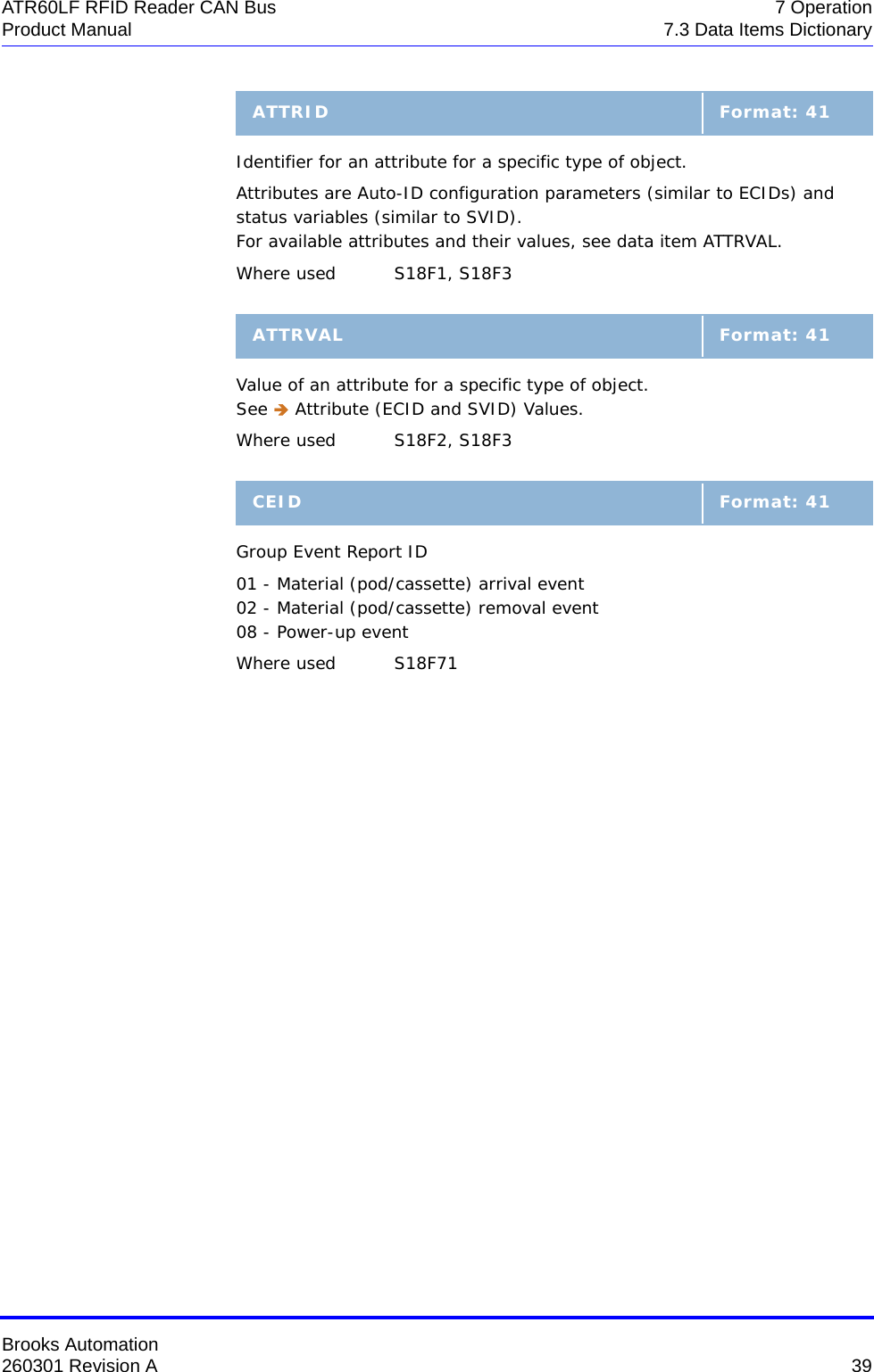
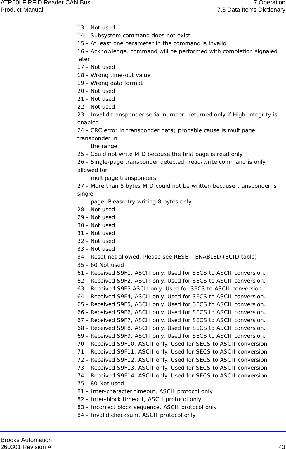
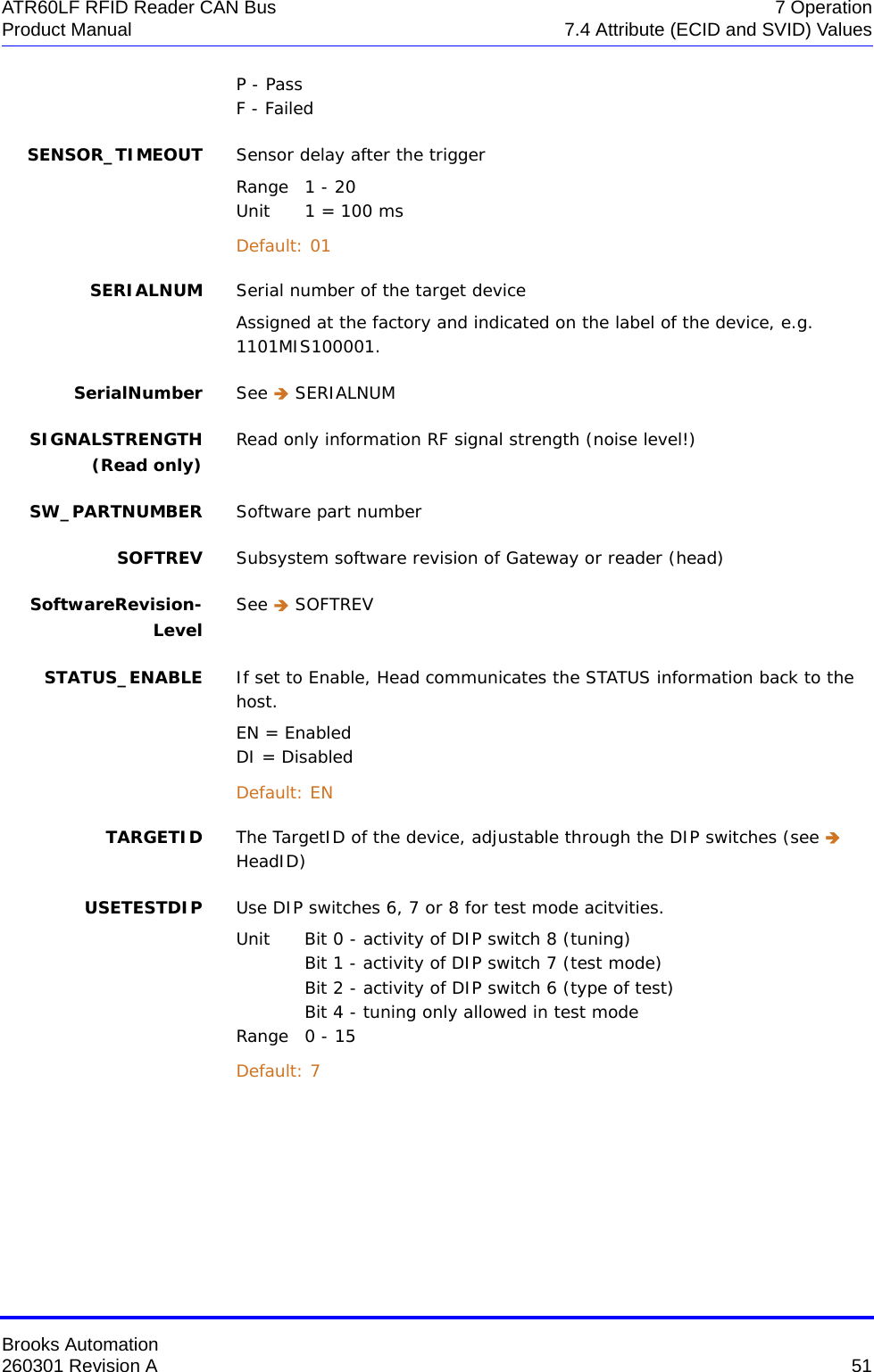
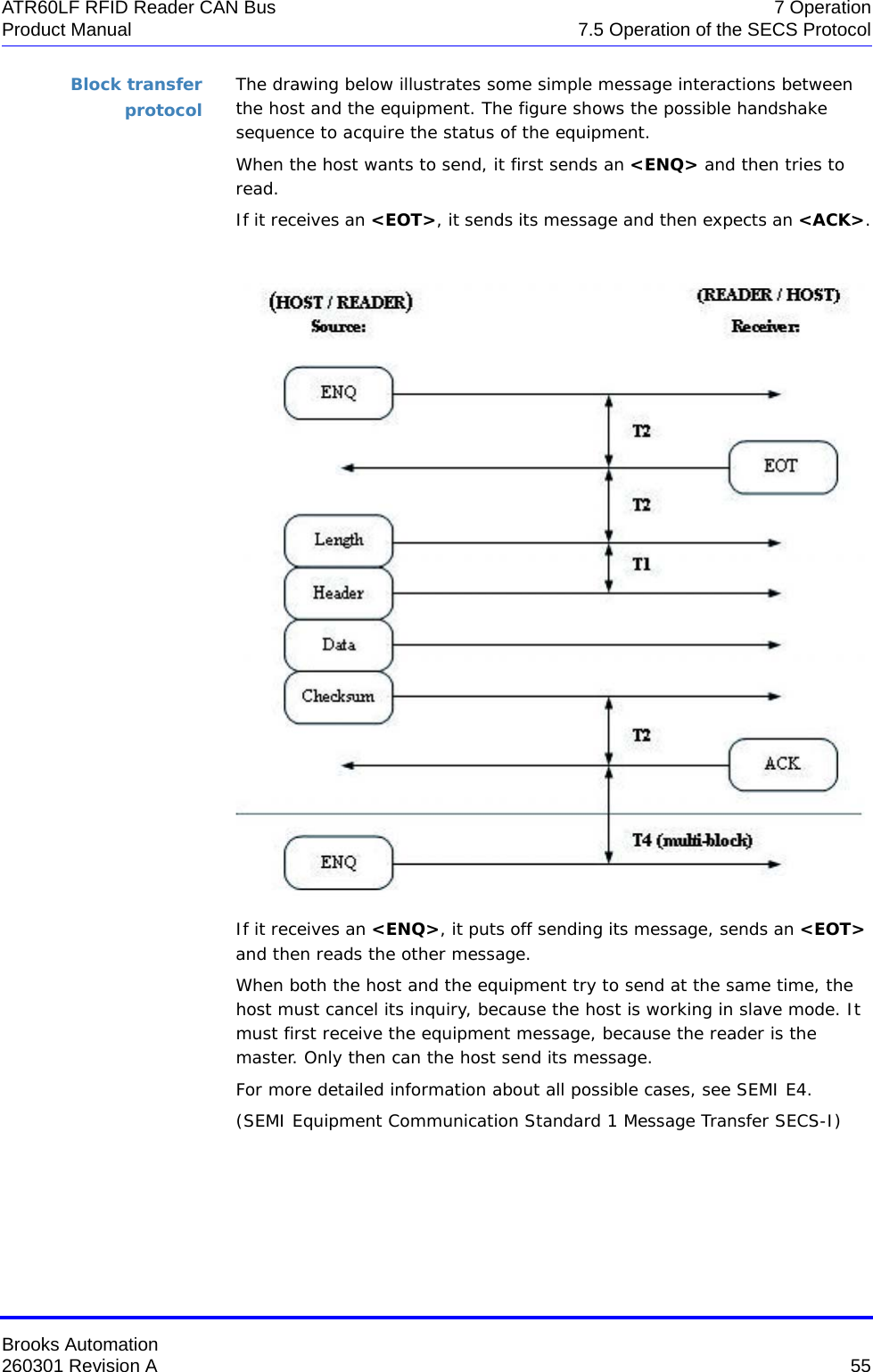
![Brooks Automation260301 Revision A 69ATR60LF RFID Reader CAN Bus 7 OperationProduct Manual 7.5 Operation of the SECS Protocol7.5.7 Message DetailsEquipment status S1F1: ARE YOU THERE REQUEST (R) H -> EThis message is used to perform a heartbeat between host and connected device.S1F1 W . * Header onlyS1F2: ON-LINE DATA (D) E -> HThe device signifies that it is online and reports the model number and the software revision of the head.S1F2 <L[2] <MDLN > <SOFTREV > > System errors S9F1: UNRECOGNIZED DEVICE ID (E -> H)The device ID in the message block header does not correspond to the equipment device ID.S9F1<MHEAD > .S9F3: UNRECOGNIZED STREAM TYPE (E -> H)The reader does not recognize the stream type in the message block header.S9F3<B[10] MHEAD > .S9F5: UNRECOGNIZED FUNCTION TYPE (E -> H)The reader does not recognize the function number in the message block header.S9F5<B[10] MHEAD > .S9F7: ILLEGAL DATA (E -> H)The reader does not recognize the data in the message.S9F7 <B[10] MHEAD > .](https://usermanual.wiki/Brooks-Automation/ATR60LFCAN/User-Guide-3210441-Page-81.png)
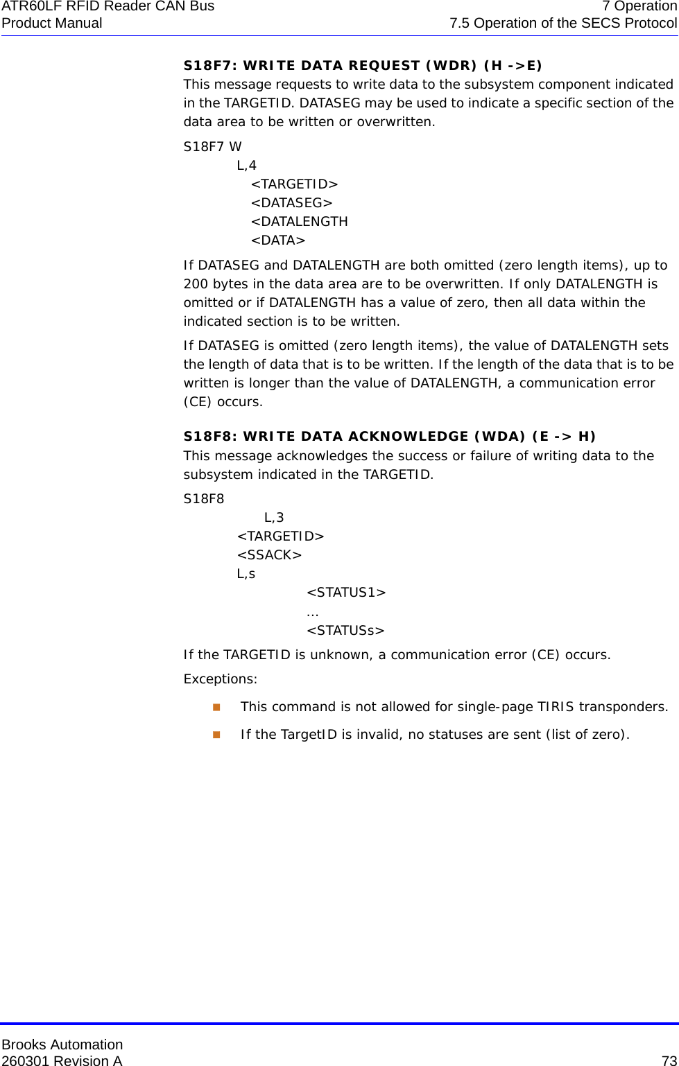
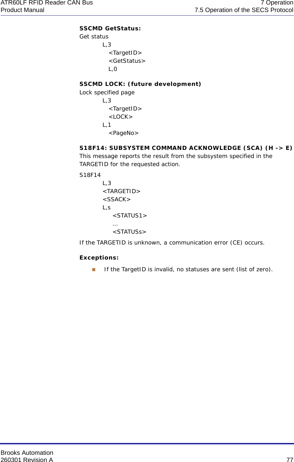
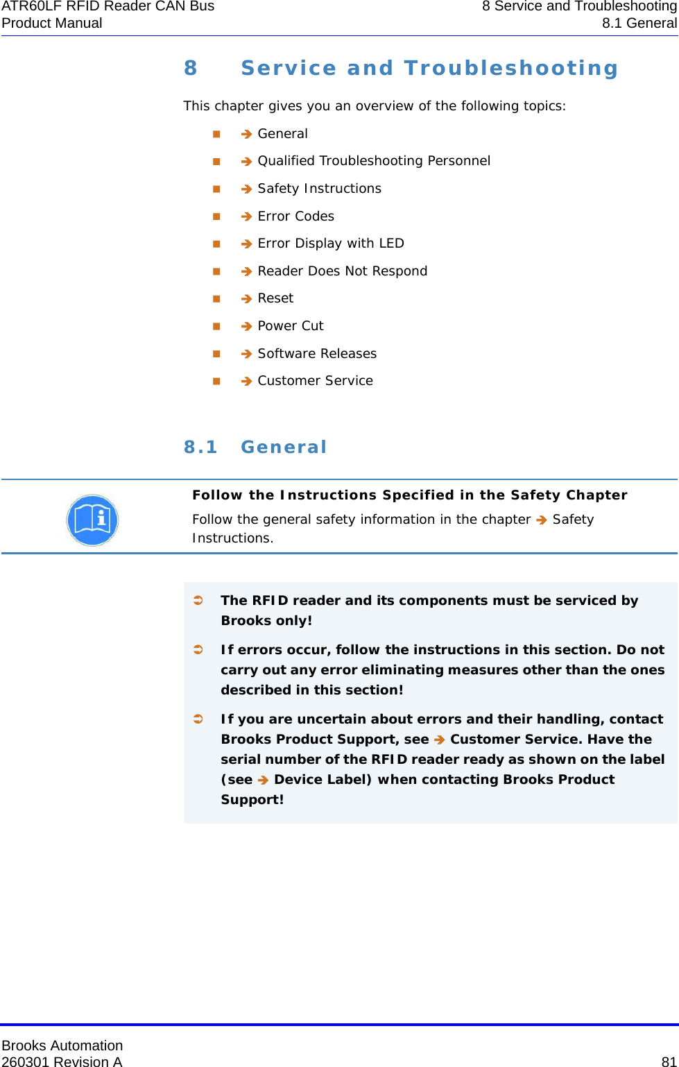
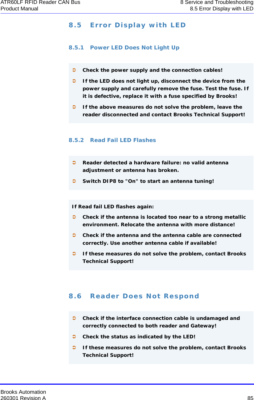
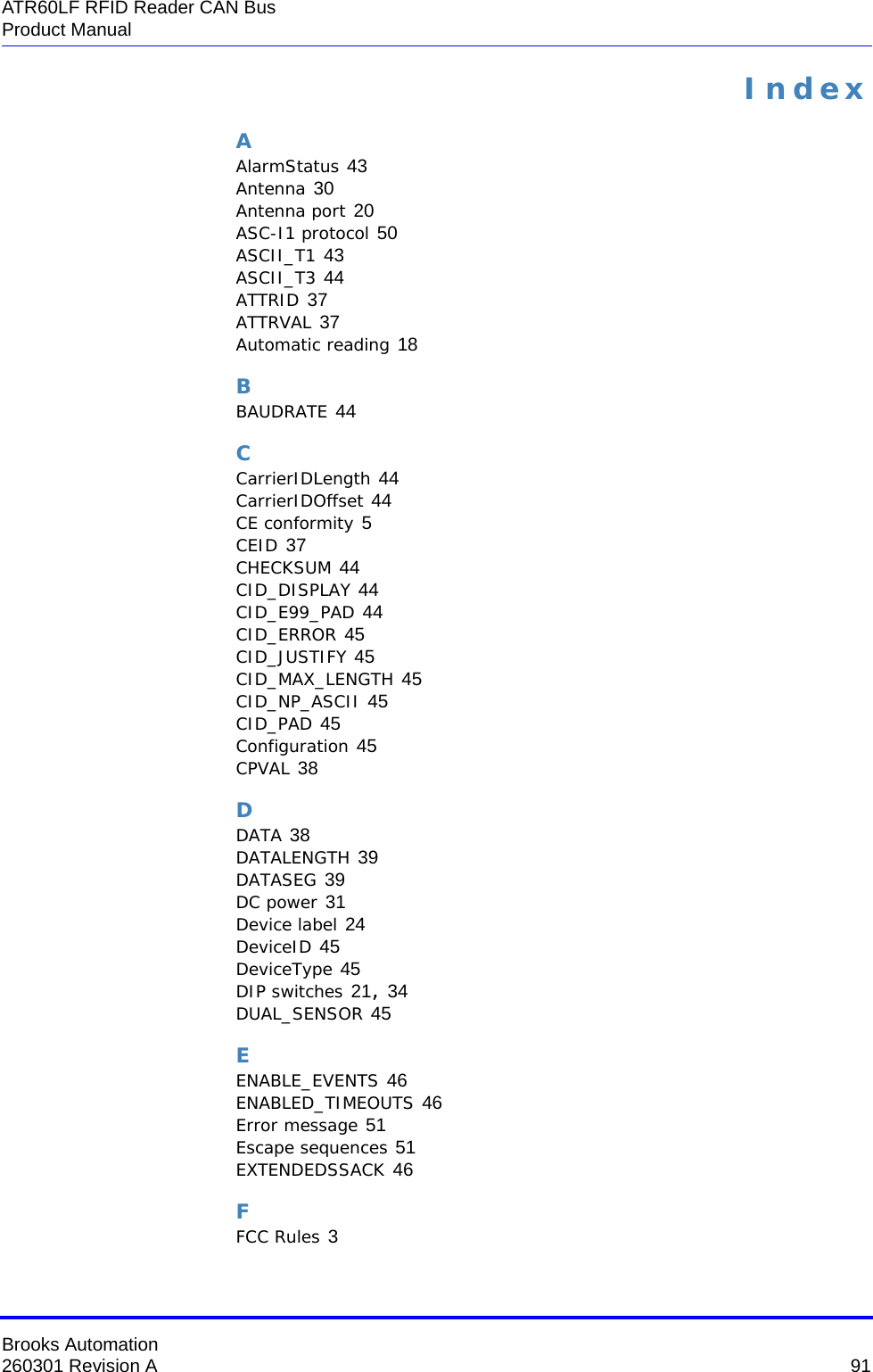
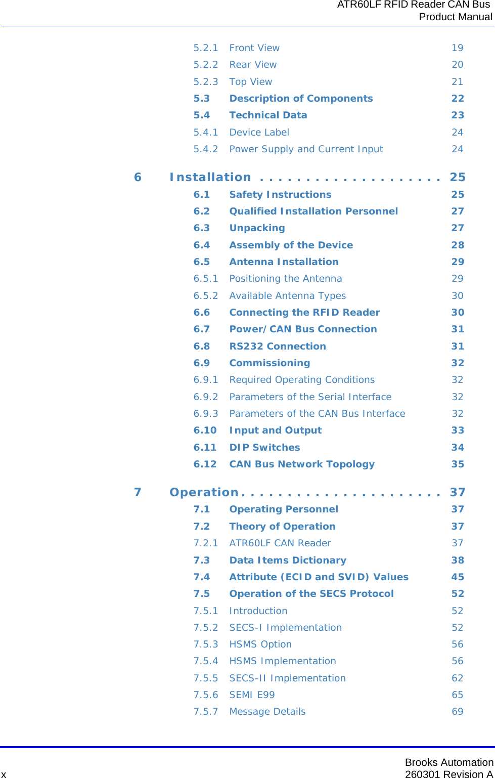
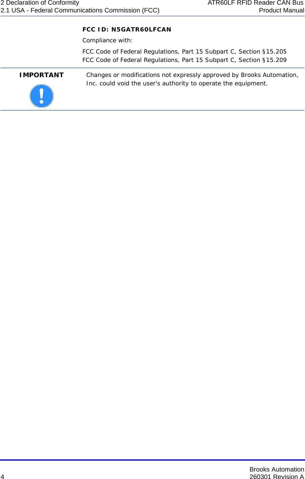
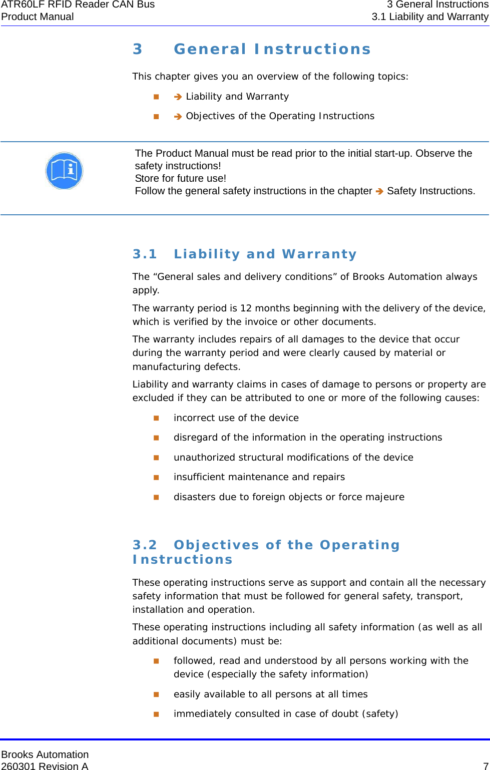
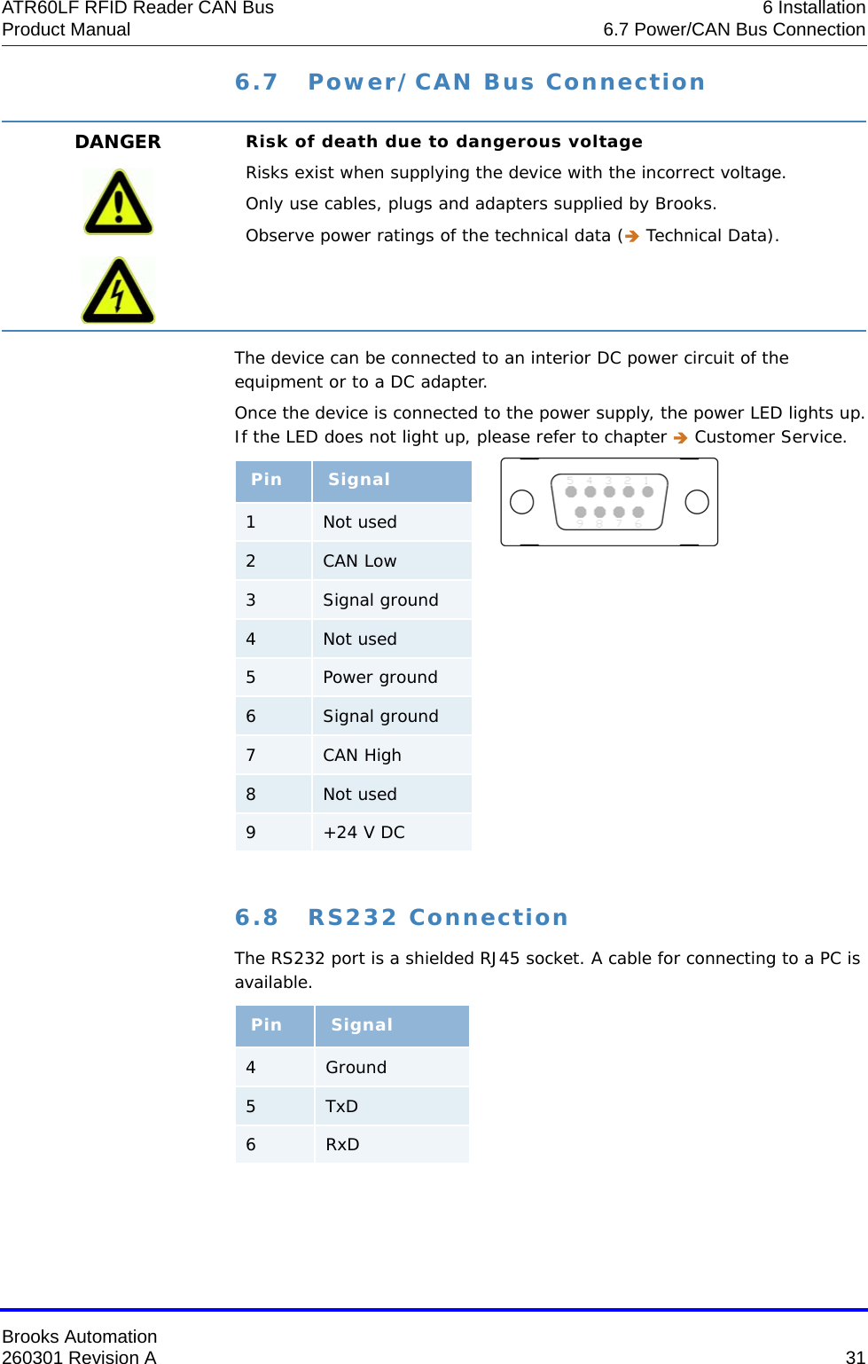
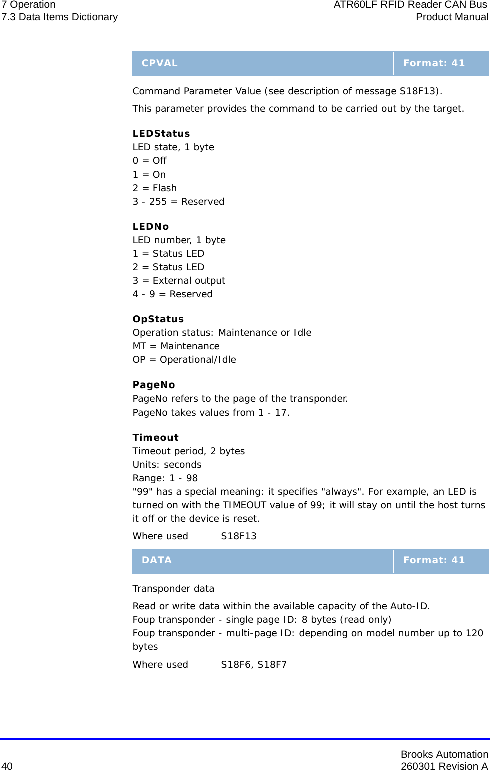
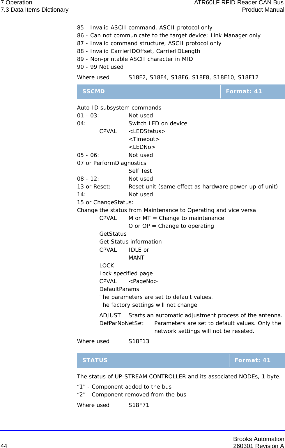
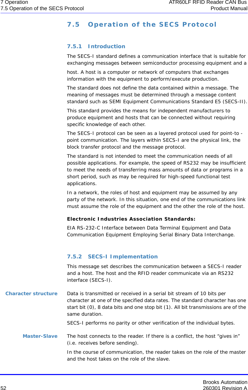
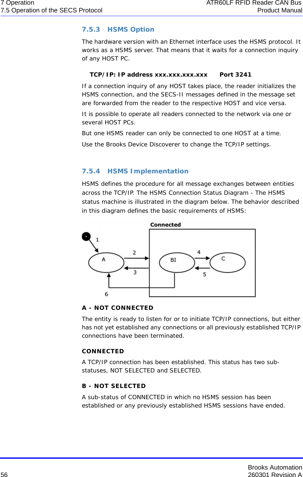
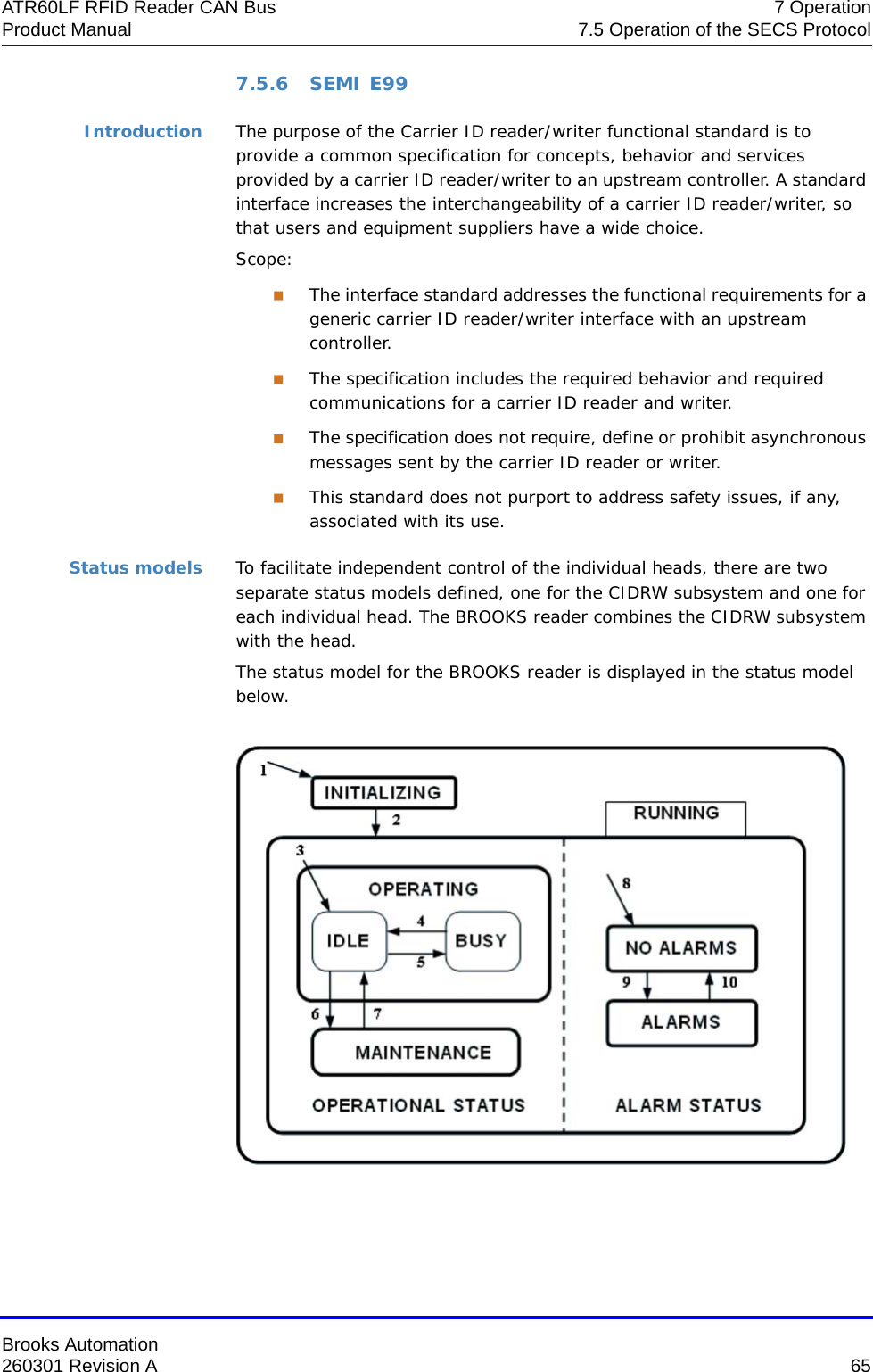
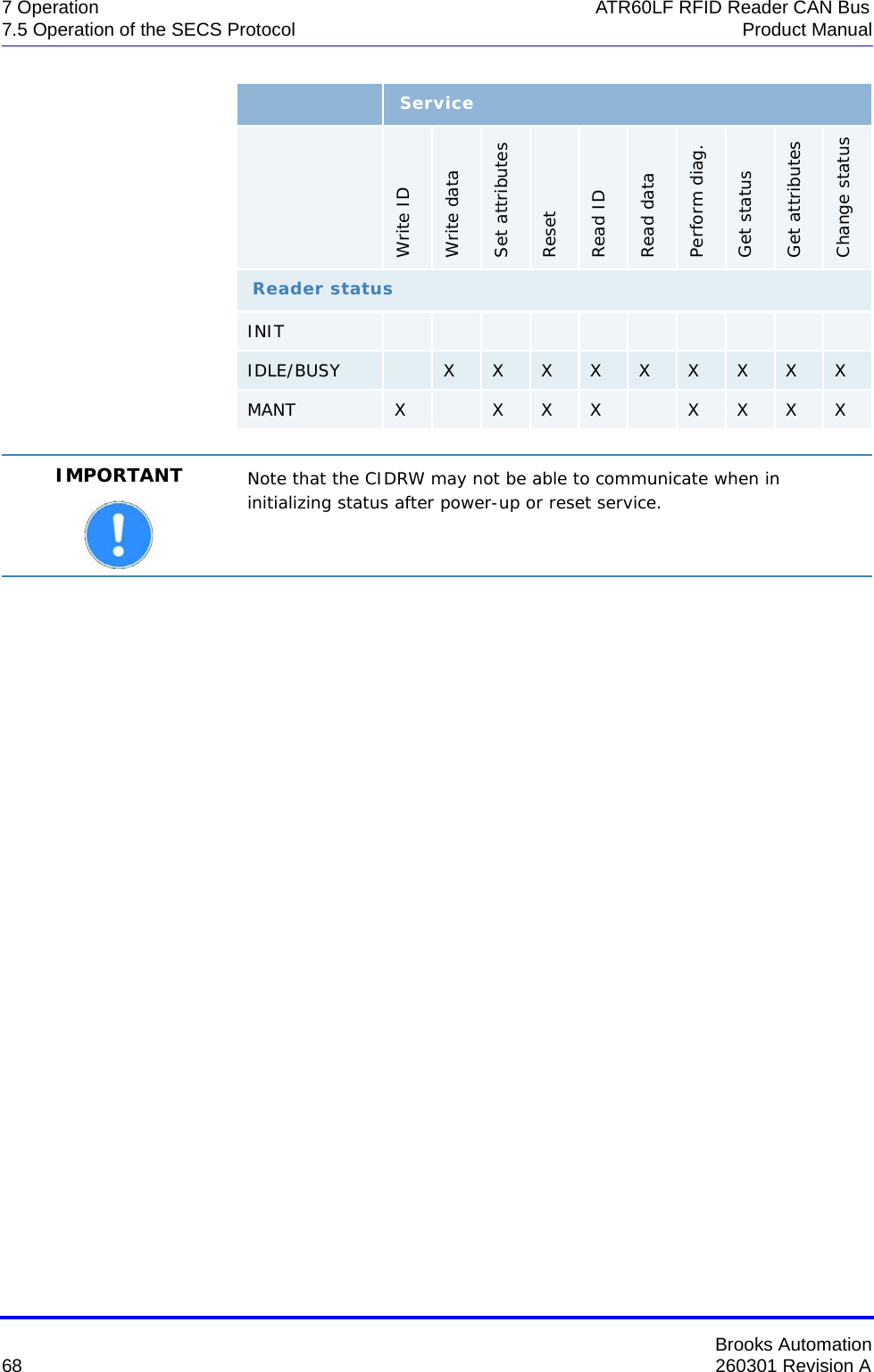
![Brooks Automation70 260301 Revision A7 Operation ATR60LF RFID Reader CAN Bus7.5 Operation of the SECS Protocol Product ManualS9F9: TRANSACTION TIMER TIMEOUT (E -> H)This message indicates that a transaction timer has timed out and that the corresponding transaction was aborted. Only the last sent message (which must be confirmed by the host) is stored and controlled.S9F9 <B[10] SHEAD > .Subsystem control and data S18F1: READ ATTRIBUTE REQUEST (RAR) (H -> E)This message requests the current values of specific attributes of the subsystem component indicated in the TARGETID.S18F1 WL,2 <TARGETID> L,n <ATTRID1> …<ATTRIDn>S18F2: READ ATTRIBUTE DATA (RAD) (E -> H)This message returns the current values of the requested attributes and the current status of the requested component indicated in the TARGETID.S18F2 L,4 <TARGETID><SSACK>L,n <ATTRVAL1> …<ATTRVALn>L,s<STATUS1> …<STATUSs>If the ATTRID of the S18F1 message is unknown, the corresponding ATTRVAL has the value <nothing>.](https://usermanual.wiki/Brooks-Automation/ATR60LFCAN/User-Guide-3210441-Page-82.png)