Brooks Automation ATR60LFCAN Low Frequency RFID Reader with CAN Bus Interface User Manual ATR60LF
Brooks Automation Inc. Low Frequency RFID Reader with CAN Bus Interface ATR60LF
User manual
ATR60LF RFID Reader CAN Bus
Product Manual
260301 Revision A

Brooks Automation
ii 260301 Revision A
ATR60LF RFID Reader CAN Bus
Product Manual

Brooks Automation
260301 Revision A iii
ATR60LF RFID Reader CAN Bus
Product Manual
Brooks Automation
Information provided within this document is subject to change without notice, and although believed to be
accurate, Brooks Automation assumes no responsibility for any errors, omissions, or inaccuracies.
ABF™, AcuLigner™, Advan Tag™, Align™, AquaTran™, AutoTeach™, ATR™, AXM™, Basic Blue™,
BioStore™, BiSymmetrik™, CenterSmart™, Cool Solutions™, Crate to Operate™, CrossingConnect™,
DARTS™, Enerta™, e-RMA™, e-Spares™, e-Volution™, Falcon™, FastRegen™, FIXLOAD™,
FrogLeg™, InLigner™, InCooler™, Interface™, Isoport™, Jet™, Jet Engine™, LowProfile™, M2 Nano™,
Mini-Ion™, PASIV™, PerformanceBlue™, Plate Auditor™, PowerPak™, PowerTools™, QuadraFly™,
Radius™, Radient™, Radient Express™, RapidThaw™, Reliance™, Reliance ATR™, RetroEase™,
SCARA™, SmartPM™, SPOTLevel™, Sprint™, Synetics™, The New Pathway to Productivity™, Time
Optimized Trajectory™, Time Optimal Trajectory™, Time Optimized Path™, TopCooler™, TopLigner™,
Tube Auditor™, Ultimate Blue™, VAC-407™, VacuTran™, VersaPort™, WaferEngine™ and the Brooks
logo are trademarks of Brooks Automation, Inc.
AcuTran®, AquaTrap®, Asyst®, Celigo®, Conductron®, Convectron®, the Cool Solutions logo, Crossing
Automation®, Cryodyne®, Cryotiger®, Cryo-Torr®, Fusion®, GOLDLink®, Guardian®, GUTS®, Helix®,
Leapfrog®,MagnaTran®, MapTrak®, Marathon®, Marathon 2®, Marathon Express®, Micro-Ion®,
MiniConvectron®, On-Board®, Polycold®, Razor®, REMP®, Spartan™, TrueBlue®, TurboPlus®, Vision®,
Xpeel®, XTape®, Zaris®, and the Brooks Automation logo are registered U.S. trademarks of Brooks
Automation, Inc.
All other trademarks are properties of their respective owners.
© 2016 Brooks Automation, Inc. All Rights Reserved. The information included in this manual is
Proprietary Information of Brooks Automation and is provided for the use of Brooks Automation customers
only and cannot be used for distribution, reproduction, or sale without the express written permission of
Brooks Automation. This information may be incorporated into the user’s documentation, however any
changes made by the user to this information is the responsibility of the user.
Accelerating Innovation

Brooks Automation
iv 260301 Revision A
ATR60LF RFID Reader CAN Bus
Product Manual
For Technical Support:
Location GUTS® Contact Number
North America +1-800-FOR-GUTS (1-800-367-4887)
+1-978-262-2900
Europe +49-1804-CALL-GUTS (+49-1804-2255-4887)
Japan +81-45-477-5980
China +86-21-5131-7066
Taiwan +886-3-5525225
Korea +82-31-288-2500
Singapore +65-6464-1481
Visit us online: www.brooks.com
Contact Technical Publications directly: Technical.Publications@brook.com
08/10/2016 Part Number 260301 Revision A
Printed in the U.S.A.
This technology is subject to United States export Administration Regulations and authorized to the
destination only; diversion contrary to U.S. law is prohibited.
Corporate Headquarters Fremont Office
15 Elizabeth Drive 46702 Bayside Parkway
Chelmsford, MA 01824 U.S.A. Fremont, CA 94539 U.S.A

Brooks Automation
260301 Revision A v
ATR60LF RFID Reader CAN Bus
Product Manual
Brooks Automation, Inc.
46702 Bayside Parkway
Fremont, CA 94538
Tel: +1 510-661-5000
Fax: +1 510-661-5166
Brooks Locations Worldwide:
Brooks Automation Inc.
15 Elizabeth Drive Chelmsford, MA
01824-2400
Tel: +1-978-262-2400
Fax: +1-978-262-2500
www.brooks.com
Brooks Life Science Systems
14100 Danielson Street, Bldg 100
Poway, CA 92064
Tel: +1 858-527-7000
Fax: +1 858-679-1255
Brooks Life Science Systems
1003 E Trent Street. Suite 110
Spokane, WA 99202
Tel: +1 234-567-8910
Fax: +1 234-567-8910
Brooks Automation, Inc.
Polycold Systems
3800 Lakeville Highway
Petaluma, CA 94954
Tel: +1 707-769-7000
Fax: +1 707-769-1380
Brooks Automation, Inc.
MicroTool Products
824 South Tejon Street
Colorado Springs, CO 80903
Tel: +1 719-471-9888
Fax: +1 719-471-9977
Brooks Automation, Inc.
9601 Dessau Road, Suite 301
Austin, TX 78754
Tel: +1 512-912-2800
Fax: +1 512-912-2888
Brooks Automation Korea, Inc.
400-2 Gomae-Dong,
Giheung-Gu, Yongin-City
Gyeonggi-Do, 446-901
Korea
Tel : +82-31-288-2500
Fax: +82-31-287-2111
Brooks Automation France
SAS Les Jardins de Maupertuis
7 Chemin de la Dhuy
Batiment Le Juparana
Meylan, France 38240
Tel: +33 (0)4.76.18.92.00
Fax: +33 (0)4.76.18.91.98
Brooks Japan K.K.
HEADQUARTERS
Nisso Bldg. No 16, 10F
3-8-8 ShinYokohama, Kohoku-ku
Yokohama, Kanagawa 222-0033
Tel: +81-45-477-5570
Fax: +81-45-477-5571
Brooks Automation, Inc.
AIM Servicios Administrativos S de RL de
CV
Carretera Huinalá km 2.8
Parque Industrial Las Américas
66640 Apodaca, NL Mexico
Tel: +52 81 8863-6363
Brooks Automation Ltd.
TAIWAN HEADQUARTERS
5F-5, No.32, Tai-Yuen Street
Chu-Pei City
Hsinchu County 302, Taiwan, R.O.C.
Tel: +886-3-552 5258
Fax (G&A): +886-3-552 5255
Fax (Sales): +886-3-552 5200
Brooks Automation (Germany) GmbH
Ernst-Ruska-Ring 11
07745 Jena, Germany
Tel: +49 3641 4821 100
Fax: +49 3641 4821 4100
Brooks Automation (Israel) Ltd.
Mevo Yerach 5
Kiryat-Gat 82000
Israel
Tel: +972 8672 2988
Fax: +972 8672 2966
Brooks Automation (Germany)
GmbH
Karl-Marx-Strasse 23
D-01109 Dresden, Germany
Tel: +49 351 885 930
Fax: +49 351 885 9322
Brooks Technology (Shanghai) Lim-
ited
2nd Floor, No. 72, 887 Zuchongzhi
Road
Zhangjiang Hi-Tech Park
Pudong, Shanghai
China 201203
Tel: +86-21-5131-7070
Fax: +86-21-5131-7068
Brooks Life Science Systems
Weststrasse 12
CH-3672 Oberdiessbach
Switzerland
Tel: +41 (0) 31 770 70 70
Fax: +41 (0) 31 770 72 66
Life Science Systems
Northbank, Irlam
Manchester M44 5AY
United Kingdom
Tel: +44 (0) 161 777 2000
Fax: +44 (0) 161 777 2002
Brooks Automation (Singapore) Pte
Ltd
1200 Depot Road
#07-01 to #07-06
Singapore 109675
Tel: +65-6836-3168
Fax: +65-6836-3177

Brooks Automation
vi 260301 Revision A
ATR60LF RFID Reader CAN Bus
Product Manual

Brooks Automation
260301 Revision A vii
ATR60LF RFID Reader CAN Bus
Product Manual
Revision History
This section gives an overview of the change history for the document.
Revision ECO
Number Date Explanation of Changes
AXXXXX 25/10/2016 Initial Release

Brooks Automation
viii 260301 Revision A
ATR60LF RFID Reader CAN Bus
Product Manual

Brooks Automation
260301 Revision A ix
ATR60LF RFID Reader CAN Bus
Product Manual
Table of Contents
Revision History . . . . . . . . . . . . . . . . .vii
1Identification . . . . . . . . . . . . . . . . . . . . 1
1.1 Model 1
1.2 Designated Use 1
1.3 Incorrect Use 2
2Declaration of Conformity. . . . . . . . . . . 3
2.1 USA - Federal Communications
Commission (FCC) 3
2.2 Europe - CE Conformity 5
3General Instructions . . . . . . . . . . . . . . 7
3.1 Liability and Warranty 7
3.2 Objectives of the Operating Instructions 7
3.2.1 Target Group 8
4Safety Instructions. . . . . . . . . . . . . . . . 9
4.1 Symbols and Signal Words 9
4.2 Area of Application and Symbols 10
4.2.1 Safety Symbols - in Compliance with
DIN 4844-2 10
4.2.2 Warning Symbols 10
4.2.3 Prohibition Symbols 11
4.2.4 Other Symbols 11
4.3 Obligations 12
4.3.1 Operating Company's Obligations 12
4.3.2 Operating Personnel's Obligations 12
4.4 ESD Instructions 13
4.5 Residual Risks 13
4.6 Additional Instructions 14
5Product Specifications . . . . . . . . . . . . 17
5.1 Function 17
5.1.1 General 17
5.1.2 Basic Functions 18
5.1.3 Normal Mode 18
5.1.4 Automatic Reading 18
5.2 Images 19

Brooks Automation
x260301 Revision A
ATR60LF RFID Reader CAN Bus
Product Manual
5.2.1 Front View 19
5.2.2 Rear View 20
5.2.3 Top View 21
5.3 Description of Components 22
5.4 Technical Data 23
5.4.1 Device Label 24
5.4.2 Power Supply and Current Input 24
6Installation . . . . . . . . . . . . . . . . . . . . 25
6.1 Safety Instructions 25
6.2 Qualified Installation Personnel 27
6.3 Unpacking 27
6.4 Assembly of the Device 28
6.5 Antenna Installation 29
6.5.1 Positioning the Antenna 29
6.5.2 Available Antenna Types 30
6.6 Connecting the RFID Reader 30
6.7 Power/CAN Bus Connection 31
6.8 RS232 Connection 31
6.9 Commissioning 32
6.9.1 Required Operating Conditions 32
6.9.2 Parameters of the Serial Interface 32
6.9.3 Parameters of the CAN Bus Interface 32
6.10 Input and Output 33
6.11 DIP Switches 34
6.12 CAN Bus Network Topology 35
7Operation. . . . . . . . . . . . . . . . . . . . . . 37
7.1 Operating Personnel 37
7.2 Theory of Operation 37
7.2.1 ATR60LF CAN Reader 37
7.3 Data Items Dictionary 38
7.4 Attribute (ECID and SVID) Values 45
7.5 Operation of the SECS Protocol 52
7.5.1 Introduction 52
7.5.2 SECS-I Implementation 52
7.5.3 HSMS Option 56
7.5.4 HSMS Implementation 56
7.5.5 SECS-II Implementation 62
7.5.6 SEMI E99 65
7.5.7 Message Details 69

Brooks Automation
260301 Revision A xi
ATR60LF RFID Reader CAN Bus
Product Manual
8Service and Troubleshooting . . . . . . . 81
8.1 General 81
8.2 Qualified Troubleshooting Personnel 82
8.3 Safety Instructions 82
8.4 Error Codes 83
8.4.1 SSACK 83
8.4.2 Stream Function 84
8.5 Error Display with LED 85
8.5.1 Power LED Does Not Light Up 85
8.5.2 Read Fail LED Flashes 85
8.6 Reader Does Not Respond 85
8.7 Reset 86
8.8 Power Cut 86
8.9 Software Releases 86
8.10 Customer Service 86
9Dismantling and Storage . . . . . . . . . . 87
9.1 Dismantling 87
9.2 Storage 87
10 Transport and Disposal. . . . . . . . . . . . 89
10.1 Transport 89
10.2 Disposal 89
Index . . . . . . . . . . . . . . . . . . . . . . . . .91

Brooks Automation
xii 260301 Revision A
ATR60LF RFID Reader CAN Bus
Product Manual

Brooks Automation
260301 Revision A 1
ATR60LF RFID Reader CAN Bus 1 Identification
Product Manual 1.1 Model
1 Identification
This chapter gives you an overview of the following topics:
Model
Designated Use
Incorrect Use
1.1 Model
ATR60LF READER CAN Bus
Serial number e.g. 1607SNI12345
Part number TLS-33C-4O00-C1-00E2
Manufacturer Brooks Automation Inc.
46702 Bayside Parkway
Fremont, CA 94538
Tel: +1 510-661-5000
Fax: +1 510-661-5166
Website www.brooks.com
For information on the label, see Device Label.
1.2 Designated Use
This product was developed for reading and writing transponders only. Any
other use of this device constitutes misuse and renders the user's authority
to install and operate the device invalid.
This product is designed to be mounted and operated in an industrial
setting as a built-in-device only. It is not designed to be used as a stand-
alone or portable device or in a non-industrial setting, such as a household,
vehicle or in the open-air.
Brooks Automation
2260301 Revision A
1 Identification ATR60LF RFID Reader CAN Bus
1.3 Incorrect Use Product Manual
Intended use also includes the following:
following all instructions in the operating instructions
observing all safety information
Before using the device, the user should ensure that the national approval
requirements for use are met.
1.3 Incorrect Use
Incorrect use, which can endanger the device, the user and third parties,
includes:
the use of the device contrary to its intended use ( Designated
Use)
modifying, extending or reconstructing the device without first
consulting Brooks Automation
operating the device when there are obvious problems
WARNING Risk of injury through incorrect modifications
There are risks from unauthorized modifications to the machine.
Only use original spare parts from Brooks. Do not make any changes,
attachments or modifications to the device without the approval of
Brooks Automation.
WARNING Risk of injury and malfunction of machine operation through
incorrect use
There are risks attached to using the device incorrectly.
Use the device exclusively according to its intended use.

Brooks Automation
260301 Revision A 3
ATR60LF RFID Reader CAN Bus 2 Declaration of Conformity
Product Manual 2.1 USA - Federal Communications Commission (FCC)
2 Declaration of Conformity
This chapter gives you an overview of the following topics:
USA - Federal Communications Commission (FCC)
Europe - CE Conformity
2.1 USA - Federal Communications
Commission (FCC)
This device complies with Part 15 of the FCC Rules. Operation is subject to
the following two conditions:
This device may not cause harmful interference.
This device must accept any interference received, including
interference that may cause undesired operation.
This equipment has been tested and found to comply with the limits for a
Class A digital device, pursuant to part 15 of the FCC Rules. These limits
are designed to provide reasonable protection against harmful interference
in a commercial environment.
This equipment generates, uses, and can radiate radio frequency energy
and, if not installed and used in accordance with the instruction manual,
may cause harmful interference to radio communications. Operation of this
equipment in a residential area is likely to cause harmful interference in
which case the user will be required to correct the interference at his own
expense.
This equipment is only intended for professional installation.

Brooks Automation
4260301 Revision A
2 Declaration of Conformity ATR60LF RFID Reader CAN Bus
2.1 USA - Federal Communications Commission (FCC) Product Manual
FCC ID: N5GATR60LFCAN
Compliance with:
FCC Code of Federal Regulations, Part 15 Subpart C, Section §15.205
FCC Code of Federal Regulations, Part 15 Subpart C, Section §15.209
IMPORTANT Changes or modifications not expressly approved by Brooks Automation,
Inc. could void the user's authority to operate the equipment.

Brooks Automation
260301 Revision A 5
ATR60LF RFID Reader CAN Bus 2 Declaration of Conformity
Product Manual 2.2 Europe - CE Conformity
2.2 Europe - CE Conformity
Declaration of Conformity
For the European Union
Document #:
Rev.: A
Description ATR60LF CAN Reader
Function: RFID Reader
Part Number: TLS-33C-XXXX-XX-XXXX
Business name and full address of the manufacturer of the machinery:
Brooks Automation Inc., 15 Elizabeth Drive, Chelmsford, MA, USA 01824
Name and address of the person, established in the Community, authorized to compile the relevant technical documentation:
Brooks Automation (Germany) GmbH, Ernst-Ruska-Ring 11, 07745 Jena, Germany
The manufacturer declares:
x That this product fulfills all the relevant provisions of Directive 1999/5/EC (R&TTE
Directive) on Radio Equipment and Telecommunication Terminal Equipment.
x The product is in conformity with the following standards and/or other normative
documents:
o HEALTH & SAFETY (Article 3(1)(a)):
IEC 60905-1 : 2013/05/28
o EMC (Article 3(1)(b)):
EN 300 330-1 V1.7.1
EN 300 330-2 V1.5.1
o SPECTRUM (Article 3(2)):
EN 301 489-1 V1.9.2
EN 301 489-3 V1.6.1
EN 55032: 2012/AC: 2013
o OTHER:
Directive 2011/65/EU of the European Parliament and of the Council of 8
June 2011 on the restriction of the use of certain hazardous substances in
electrical and electronic equipment.
Signature
Date: 18-Oct-2016
Location: Fremont CA, USA

Brooks Automation
6260301 Revision A
2 Declaration of Conformity ATR60LF RFID Reader CAN Bus
2.2 Europe - CE Conformity Product Manual

Brooks Automation
260301 Revision A 7
ATR60LF RFID Reader CAN Bus 3 General Instructions
Product Manual 3.1 Liability and Warranty
3 General Instructions
This chapter gives you an overview of the following topics:
Liability and Warranty
Objectives of the Operating Instructions
3.1 Liability and Warranty
The “General sales and delivery conditions” of Brooks Automation always
apply.
The warranty period is 12 months beginning with the delivery of the device,
which is verified by the invoice or other documents.
The warranty includes repairs of all damages to the device that occur
during the warranty period and were clearly caused by material or
manufacturing defects.
Liability and warranty claims in cases of damage to persons or property are
excluded if they can be attributed to one or more of the following causes:
incorrect use of the device
disregard of the information in the operating instructions
unauthorized structural modifications of the device
insufficient maintenance and repairs
disasters due to foreign objects or force majeure
3.2 Objectives of the Operating
Instructions
These operating instructions serve as support and contain all the necessary
safety information that must be followed for general safety, transport,
installation and operation.
These operating instructions including all safety information (as well as all
additional documents) must be:
followed, read and understood by all persons working with the
device (especially the safety information)
easily available to all persons at all times
immediately consulted in case of doubt (safety)
The Product Manual must be read prior to the initial start-up. Observe the
safety instructions!
Store for future use!
Follow the general safety instructions in the chapter Safety Instructions.

Brooks Automation
8260301 Revision A
3 General Instructions ATR60LF RFID Reader CAN Bus
3.2 Objectives of the Operating Instructions Product Manual
Objectives:
to avoid accidents
to increase the service life and reliability of the device
to reduce costs due to production downtimes
3.2.1 Target Group
The operating instructions are addressed to personnel with the following
areas of responsibility:
Definition according to DIN EN 60204-1:
Instructed personnel:
Persons who have been instructed and, if required, trained by a specialist
as to the tasks assigned to them, the possible risks of incorrect behavior
and the required safety equipment and safety measures.
Specialized personnel:
Persons who can evaluate the work assigned to them and recognize
possible risks based on their specialized training, knowledge, experience
and familiarity with the relevant standards.
Area of responsibility Competence
Installation, transport and storage Specialized personnel
Commissioning, operation and
decommissioning Instructed personnel
Troubleshooting Specialized personnel
Brooks Automation
260301 Revision A 9
ATR60LF RFID Reader CAN Bus 4 Safety Instructions
Product Manual 4.1 Symbols and Signal Words
4 Safety Instructions
This chapter gives you an overview of the following topics:
Symbols and Signal Words
Area of Application and Symbols
Obligations
ESD Instructions
Residual Risks
Additional Instructions
4.1 Symbols and Signal Words
The following symbols and signal words are used in this documentation.
The combination of a pictograph and a signal word classifies the respective
safety information. The symbol can vary depending on the type of danger.
Symbol Signal word Description
Death
DANGER This signal word must be used if
death or irreversible damage to
health can occur if the hazard
information is not followed.
Risk of injury and
property damage
WARNING This signal word indicates bodily
injuries and property damage
including injuries, accidents, and
health risks.
CAUTION This signal word indicates a risk of
property damage. In addition, there is
a slight risk of injuries.
No damage
ATTENTION This signal word warns of
malfunctions and may only be used if
no damage to health can occur.
IMPORTANT This signal word indicates cross-
references and ways in which
operations are facilitated. It excludes
all risks of property damage and
injury risks.
Brooks Automation
10 260301 Revision A
4 Safety Instructions ATR60LF RFID Reader CAN Bus
4.2 Area of Application and Symbols Product Manual
4.2 Area of Application and Symbols
The device was constructed according to state-of-the-art technology and
recognized safety regulations. In order to prevent any risks to life and limb
of the user, third parties or damage to the device, only use the device for its
intended purpose and in perfect condition with regard to safety.
Bodily injuries and/or property damage resulting from non-compliance with
the instructions given in the operating instructions are the responsibility of
the company operating the device or of the assigned personnel.
Malfunctions that could compromise safety must be eliminated
immediately.
4.2.1 Safety Symbols - in Compliance with DIN 4844-2
Special safety symbols in accordance with DIN 4844-2 are used in the
corresponding passages in the text of these operating instructions and
require special attention depending on the combination of signal word and
symbol.
4.2.2 Warning Symbols
DANGER Danger to Life, Risk of Injuries or Loss of Property
Risks exist when disregarding the operating instructions and the safety
instructions therein.
Carefully read the operating instructions before initial commissioning.
Perform the required safety measures before initial commissioning.
Follow the general safety information as well as the special safety
information given in other chapters.
WARNING Risk of Injuries When Disregarding Safety Symbols
Risks exist when disregarding warnings in the operating instructions.
Please heed the warnings.
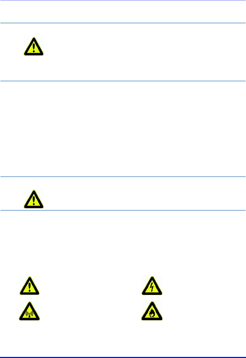
Warning: Hazardous
area Warning against
hazardous electrical
voltage
Warning against
electromagnetic
radiation
Warning: Flammable
materials
Brooks Automation
260301 Revision A 11
ATR60LF RFID Reader CAN Bus 4 Safety Instructions
Product Manual 4.2 Area of Application and Symbols
4.2.3 Prohibition Symbols
4.2.4 Other Symbols
Warning: Potentially
explosive
atmosphere
Warning against
electrostatically
sensitive
components
Unauthorized access
is prohibited Fire, open flame and
smoking is
prohibited
Switching is
prohibited Prohibition
Dispose of packing
material according to
regulations
Recycling
Important
information Refer to manual
Disconnect from
power supply

Brooks Automation
12 260301 Revision A
4 Safety Instructions ATR60LF RFID Reader CAN Bus
4.3 Obligations Product Manual
4.3 Obligations
4.3.1 Operating Company's Obligations
The safe condition and use of the device is a requirement for the safe
operation of the device. The company operating the device therefore has
the obligation to ensure that the following points are adhered to:
4.3.2 Operating Personnel's Obligations
Operators are obligated to contribute to the prevention of work accidents
and the consequences of them by their personal conduct.
The device may only be operated by trained and authorized
personnel!
Prevent unsafe and/or dangerous work procedures! If
necessary, check employees' actions!
Only permit personnel to be trained or instructed within the
scope of general training on the device under the supervision
of an experienced person!
Personnel must have understood the operating instructions.
Have this confirmed by signature!
Precisely establish responsibilities according to the various
task areas (operation, installation)!
Operating personnel must be committed to immediately
reporting to their superior any identifiable safety deficiencies
which occur!
WARNING Risk of injuries due to insufficient personnel qualifications
A risk exists for personnel and the proper operation due to insufficiently
qualified personnel.
Only trained personnel may operate the device. New operators must be
instructed by the current operating personnel. The operating company
must precisely regulate and monitor the personnel's areas of
responsibility and competence.
Personnel for the areas of responsibility mentioned above must have the
corresponding qualification for this work (training, instructions). If
necessary, this can be done by Brooks on behalf of the operating
company.
All warranty claims are void when disregarded.
Brooks Automation
260301 Revision A 13
ATR60LF RFID Reader CAN Bus 4 Safety Instructions
Product Manual 4.4 ESD Instructions
4.4 ESD Instructions
4.5 Residual Risks
Even if all precautions have been taken, there may be unapparent residual
risks!
Adhering to the safety instructions, the intended use and the operating
instructions as a whole can reduce residual risks!
CAUTION Static electricity can damage electronic components in the device. All
persons installing or maintaining the device must be trained in ESD
protection.
ESD protective measures must be applied when opening the device.
Disconnect the power supply prior to removing or adding
components!
Discharge your body and all tools used prior to touching any
components on the interior of the device!
Touch electronically sensitive parts carefully and only at their
corners!
DANGER Risks from electric current
Electrical energy remains in lines, equipment and devices even when the
device is switched off.
Only allow qualified electricians to perform work on the electrical supply
system.
ATTENTION Disconnect the device from the power supply system if active parts of
the device can be accessed with tools. Access is only permitted for
authorized personnel.
Regularly check the electrical equipment of the device. Regularly check
all moving cables for damage within the scope of maintenance and
repairs.
Brooks Automation
14 260301 Revision A
4 Safety Instructions ATR60LF RFID Reader CAN Bus
4.6 Additional Instructions Product Manual
4.6 Additional Instructions
Read and understand all safety and operating instructions prior to
installing and operating the device.
This documentation was written for specifically trained personnel.
The installation, operation and defect management may only be
carried out by specifically trained personnel.
Retain these instructions. Keep this documentation in a location
that is accessible to all personnel involved with the installation, use
and troubleshooting of the device.
Observe all warnings. Follow all warnings on and in the device and
in the documentation.
Install the device only in accordance with Brooks instructions.
Use only the accessories and cables supplied by Brooks.
Troubleshooting that is not described in the chapter Service and
Troubleshooting may only be performed by Brooks.
People with hearing aids should be aware that the radio signals
emitted by the device can cause annoying noises in the hearing
aid.
Do not connect the device to power supplies such as normal
household electrical outlets. The device should only be connected
to power supplies as specified in this document.
DANGER Risk of fire and explosions
Fire and explosions may occur within the vicinity of the device.
Smoking, open flames and fire are strictly prohibited in the vicinity of the
device. Do not store any flammable liquids within the hazardous area.
Keep a fire extinguisher in the vicinity of the device.
WARNING Warning against electromagnetic radiation
Electromagnetic radiation develops when transmitting and receiving
data.

Brooks Automation
260301 Revision A 15
ATR60LF RFID Reader CAN Bus 4 Safety Instructions
Product Manual 4.6 Additional Instructions
When removing a cable, only pull on the plug and not on the cable.
Connect cable connectors straight and carefully to avoid damaging
the contacts.
Never bend the antenna cables too far or subject them to
mechanical forces.
When spare parts are required, use only the spare parts that were
specified by Brooks. Unauthorized spare parts can result in fire,
electric shock or other hazards.
Rules and
regulations The provisions of the accident-prevention regulations of the government
safety organizations always apply to all work on the device.
The following must also be observed:
applicable legally binding accident-prevention regulations
applicable binding regulations at the place of use
the recognized technical rules for safe and professional work
existing environmental protection regulations
other applicable regulations

Brooks Automation
16 260301 Revision A
4 Safety Instructions ATR60LF RFID Reader CAN Bus
4.6 Additional Instructions Product Manual

Brooks Automation
260301 Revision A 17
ATR60LF RFID Reader CAN Bus 5 Product Specifications
Product Manual 5.1 Function
5 Product Specifications
This chapter gives you an overview of the following topics:
Function
Images
Description of Components
Technical Data
5.1 Function
5.1.1 General
The BROOKS RFID reader system is a radio-frequency identification
system.
The reader of the system sends an electromagnetic field to the battery-free
transponder via the antenna. This activates the transponder and sends the
stored data back to the reader.
The total reading cycle takes less than 100 ms.
Since a sight connection between the transponder and the reader is not
absolutely necessary, the transponder can also be identified through non-
metallic material.
The data received by the RFID reader is transmitted to the RFID CAN
Gateway via:
CAN Bus Interface

Brooks Automation
18 260301 Revision A
5 Product Specifications ATR60LF RFID Reader CAN Bus
5.1 Function Product Manual
5.1.2 Basic Functions
The reader can support various basic functions:
Reading of data
Writing of data
Setting and reading reader parameters
Subsystem commands
Read status
5.1.3 Normal Mode
In normal mode the Brooks RFID reader is ready for operation directly after
a hardware reset. ATR60LF also sends an power up event to the host when
it starts up. In this mode it does not perform any independent actions. The
latter usually have to be triggered by the host issuing protocol commands.
The exceptions are sensors and pushbuttons that on some Brooks device
variants are located on the exterior of the housing. Status changes at the
inputs generate messages that are automatically sent to the host, provided
a connection exists.
Individual protocol commands can be sent to the device as soon as the
reader has been connected to the Gateway. For communication the default
settings of the CAN Bus interface have to be observed ( Parameters of the
CAN Bus Interface).
5.1.4 Automatic Reading
Brooks RFID CAN Bus readers provide the option of “Automatic Reading”. In
this case a read operation is performed which is triggered by a sensor. If a
connection exists, the data of the automatic read operation is then sent to
the host immediately.
This automatic read operation is enabled by multiple parameters. After a
defined sensor delay time the reader detects the sensor change. With the
“Watchport” parameter the behavior is defined for when a sensor change
has been detected. With the „PIP_XYZ“ parameters the behavior of the
automatic reading is enabled and adjusted. If the read function has been
enabled, the device performs the automatic read operation independently.
Brooks Automation
260301 Revision A 19
ATR60LF RFID Reader CAN Bus 5 Product Specifications
Product Manual 5.2 Images
5.2 Images
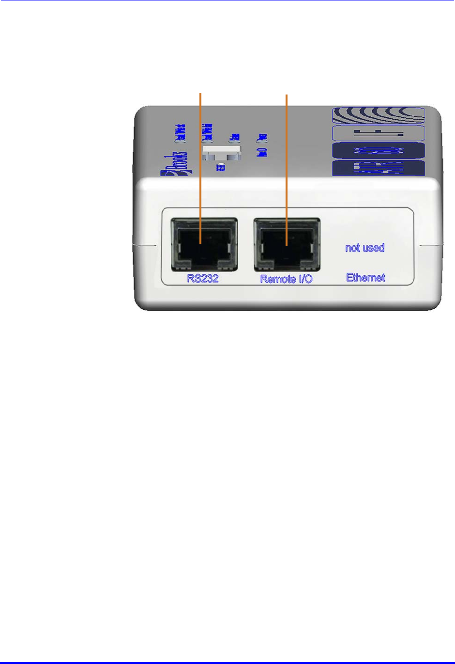
5.2.1 Front View
1RS232 port
2Remote I/O port
12
Brooks Automation
20 260301 Revision A
5 Product Specifications ATR60LF RFID Reader CAN Bus
5.2 Images Product Manual
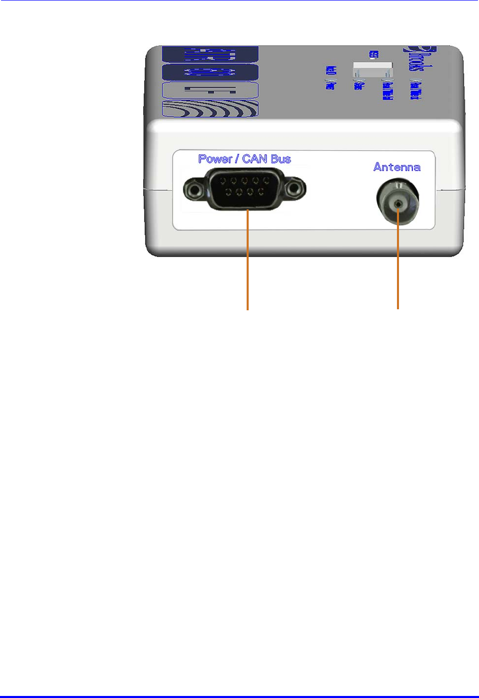
5.2.2 Rear View
1Power/CAN bus connection
2Antenna port
2
1
Brooks Automation
260301 Revision A 21
ATR60LF RFID Reader CAN Bus 5 Product Specifications
Product Manual 5.2 Images
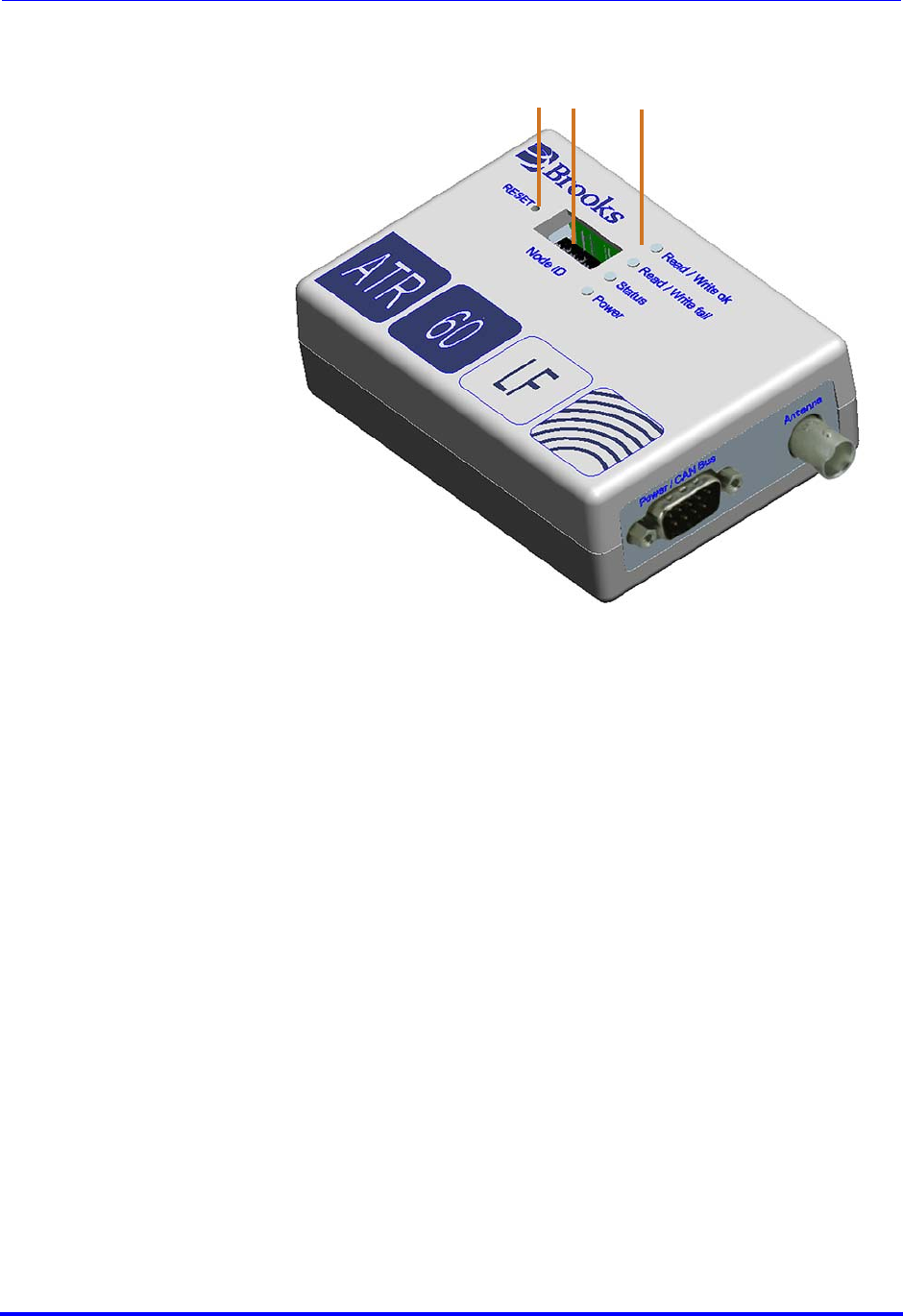
5.2.3 Top View
1Reset button
2DIP switches
3Status LEDs
3
2
1

Brooks Automation
22 260301 Revision A
5 Product Specifications ATR60LF RFID Reader CAN Bus
5.3 Description of Components Product Manual
5.3 Description of Components
Components Description
RS232 interface The data are passed down serially to the RS232
interface (RJ45) with the different protocols. Baud
rates of 4,800 up to 57,600 Bd are possible.
Remote I/O The Remote I/O port is used for external presence
sensors and an external output like a LED for
status indication.
Power / CAN Bus
connection Connector for power supply and CAN Bus
Antenna port Port for connecting an antenna
Reset button If the Reset button will be pressed a short time,
the communication parameters of the reader will
be reseted to default values. The network
settings, RS232, RS485, and protocol timer
parameters are involved. The CID parameters will
not be changed.
If the Reset button will be pressed longer than 5
seconds, the reader is restarted and all
parameters are set to default values.
DIP switches The DIP switches are used for setting the reader
address, test mode, protocol selection, switching
between reading and writing action in test mode
and for activation of automatic antenna tuning (
DIP Switches)
Power LEDs If the correct power supply is connected to the
device, the power LED lights up green and the
device is ready for operation.
Status LED The status LED indicates the current status of the
device.
Read / write ok
and Read / write
fail LED
The two Read / write LEDs indicate the result of
the last read or write action.

Brooks Automation
260301 Revision A 23
ATR60LF RFID Reader CAN Bus 5 Product Specifications
Product Manual 5.4 Technical Data
5.4 Technical Data
Technical data - device
Operating temperature 0 °C to +50 °C
32 °F to 122 °F
Storage temperature -20 °C to +70 °C
-4 °F to +158 °F
Permissible humidity at 50 °C / 122
°F 25 - 80%
Frequency 134.2 kHz
Protection class IP40
Housing material PS
Weight about 180 g l 6.35 oz.
Dimensions 111.5 x 80 x 35 mm
4.4 x 3.1 x 1.4 in.
Fuse 375 mA (T)
Serial interface RS232 4,800 Bd - 57,600 Bd
CAN Bus interface 500 kBits/sec
Vibration/shock test EN 60721-3-3:1995 Class 3M4

Brooks Automation
24 260301 Revision A
5 Product Specifications ATR60LF RFID Reader CAN Bus
5.4 Technical Data Product Manual
5.4.1 Device Label
The device label with the CE mark, part and serial number is on the device
housing.
5.4.2 Power Supply and Current Input
1Part number
2Serial number (example)
3FCC ID
Description Min Type Max Unit
Voltage (proof against connecting to
the wrong port) 18 24 30 V DC
Current (reading/writing)
pulsed current (70 ms)
100
400
mA
Current (passive) 80 mA
2
1
3
Brooks Automation
260301 Revision A 25
ATR60LF RFID Reader CAN Bus 6 Installation
Product Manual 6.1 Safety Instructions
6 Installation
This chapter gives you an overview of the following topics:
Safety Instructions
Qualified Installation Personnel
Unpacking
Assembly of the Device
Antenna Installation
Connecting the RFID Reader
Power/CAN Bus Connection
RS232 Connection
Commissioning
Input and Output
DIP Switches
6.1 Safety Instructions
Follow the Instructions in the Safety Chapter
Follow the general safety instructions in the chapter Safety
Instructions.
CAUTION The device is designed for indoor use in an industrial setting only.
Installation is only allowed in an interior room at a constant temperature
between 0° C / 32 °F and +50 °C / 122 °F, and a relative humidity
between 25 % and 80 %.
Never use the device near or in water.
Never pour liquids of any type over the device. If the device should
accidentally come in contact with liquid, disconnect it and have it
checked by a technician.
Do not install the device near heat sources such as radiators, heat
registers, stoves or other devices (including amplifiers) that generate
heat.
Do not install the device in a flammable environment.
Brooks Automation
26 260301 Revision A
6 Installation ATR60LF RFID Reader CAN Bus
6.1 Safety Instructions Product Manual
CAUTION Never expose the device to extreme temperature fluctuations, since
otherwise condensation develops in the device and causes damage.
Do not install the device in the vicinity of voltage lines or other power
lines with which they could collide (for example, when drilling), which
could result in serious injuries or even death.
The device (especially the antenna) should not be installed in the
immediate vicinity of electrical equipment such as medical devices,
monitors, telephones, TV sets, magnetic disks and metal objects.
This could result in reduced read and write ranges.
Never use the device in explosive areas (such as paint warehouses).
CAUTION Do not use the device in areas where it is exposed to vibrations or
shocks.
ATTENTION The installation location must be adequately illuminated during the
installation.
Never install the device during a lightning storm.
Verify that the installation meets the requirements of the (country
specific) FCC for human exposure to radio frequencies.
ATTENTION When determining the installation site, keep in mind the length of the
antenna wire and the read/write range of the antenna used.
Brooks Automation
260301 Revision A 27
ATR60LF RFID Reader CAN Bus 6 Installation
Product Manual 6.2 Qualified Installation Personnel
6.2 Qualified Installation Personnel
6.3 Unpacking
The device and the accessories are packed under clean-room conditions. In
order to maintain this condition, the device must also be unpacked in clean-
room conditions.
Disposing of the
packaging material
CAUTION The installation is to be carried out by specially trained personnel only. If
you are uncertain about their qualification, contact Brooks.
CAUTION Operating the device without special training can result in damage to the
reader and/or connected devices.
The packaging material consists of cardboard and foil. Dispose of these
materials separately and observing the respective regulations of your
country.
Brooks Automation
28 260301 Revision A
6 Installation ATR60LF RFID Reader CAN Bus
6.4 Assembly of the Device Product Manual
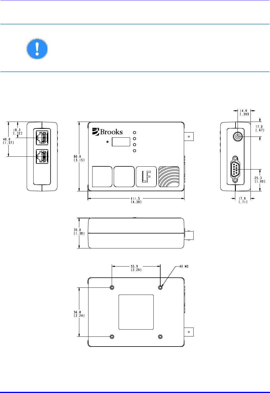
6.4 Assembly of the Device
Installation
dimensions
ATTENTION The mounting surface must be stable, non-flammable, dry and clean.
If necessary, clean it before installing the device.
The device must be installed so that air can freely circulate vertically
through the heat sink, and the operating and environmental conditions
specified under Technical Data are met at all times.
ATR
60
RESET
Node ID Power
Status
Read/Write ok
Read/Write fail
Antenna
not used
EthernetRemote I/ORS232
Power/CAN Bus
Brooks Automation
260301 Revision A 29
ATR60LF RFID Reader CAN Bus 6 Installation
Product Manual 6.5 Antenna Installation
6.5 Antenna Installation
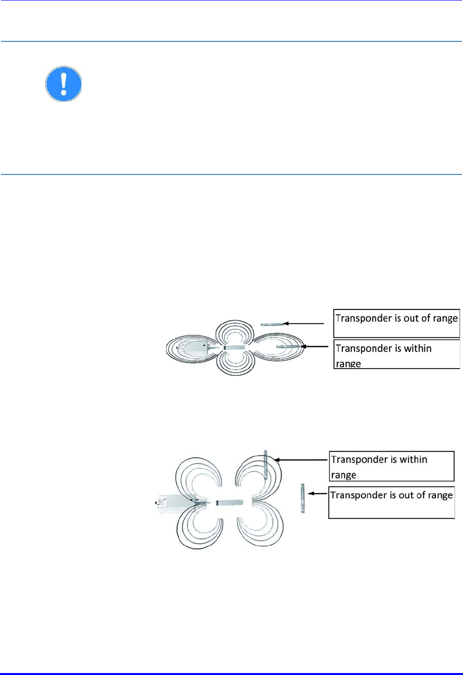
6.5.1 Positioning the Antenna
Reliable reading and writing depends on the distance from and orientation
of the transponder to the antenna.
ATTENTION When installing the antenna, consider the required reading and writing
ranges. The reader can only be used properly if the transponder is
located within the individual reading/writing range of the antenna.
If the transponder is very close to the antenna, the transponder may be
de-tuned by the metal of the antenna and a reading/writing is not
possible. We recommend keeping a minimum distance between
transponder and antenna of about 10 mm.
After antenna installation the antenna should be tuned ( DIP
Switches).
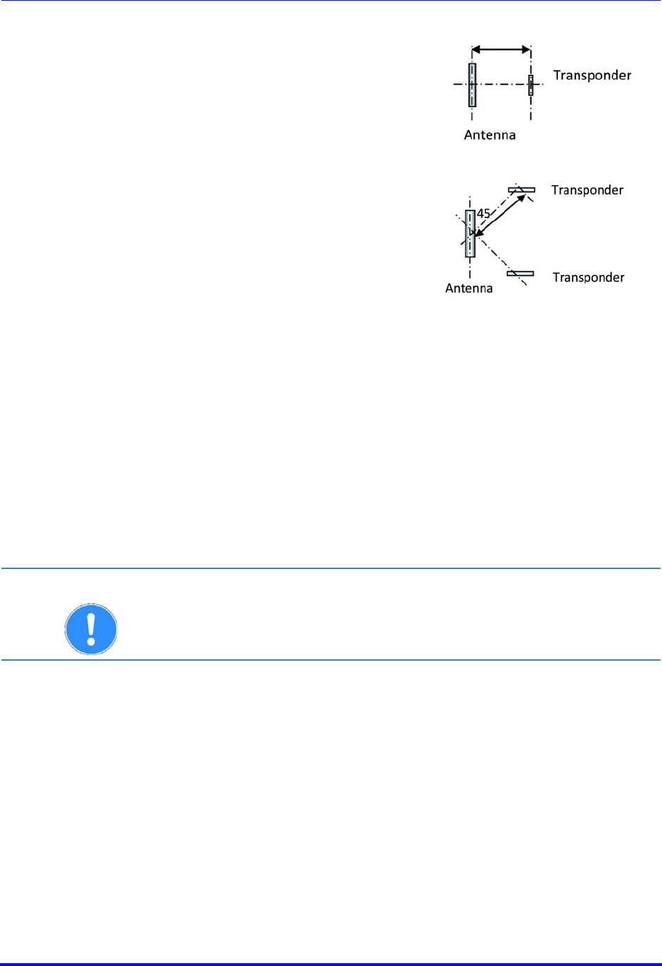
Transponder parallel to the axis of the antenna:
Transponder perpendicular to the axis of the antenna:
Brooks Automation
30 260301 Revision A
6 Installation ATR60LF RFID Reader CAN Bus
6.6 Connecting the RFID Reader Product Manual
6.5.2 Available Antenna Types
Different types of antennas are available on request.
6.6 Connecting the RFID Reader
Connect the antenna to the antenna port ( Rear View) and tune the
antenna.
Connect the reader to a power supply ( Front View) and a Gateway
connection (CAN).
Parallel The illustration
shows the optimal
position of the
transponder if it is
positioned parallel to
the axis of the
antenna.
Perpendicular The illustration
shows the optimal
position of the
transponder if it is
perpendicular to the
axis of the antenna.
ATTENTION The antenna-connector housing should have no connection to other
objects,
e.g. mounting plate!
Brooks Automation
260301 Revision A 31
ATR60LF RFID Reader CAN Bus 6 Installation
Product Manual 6.7 Power/CAN Bus Connection
6.7 Power/CAN Bus Connection
The device can be connected to an interior DC power circuit of the
equipment or to a DC adapter.
Once the device is connected to the power supply, the power LED lights up.
If the LED does not light up, please refer to chapter Customer Service.
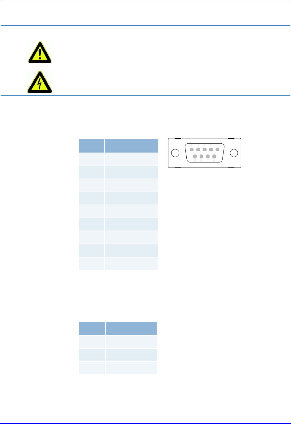
6.8 RS232 Connection
The RS232 port is a shielded RJ45 socket. A cable for connecting to a PC is
available.
DANGER Risk of death due to dangerous voltage
Risks exist when supplying the device with the incorrect voltage.
Only use cables, plugs and adapters supplied by Brooks.
Observe power ratings of the technical data ( Technical Data).
Pin Signal
1Not used
2CAN Low
3Signal ground
4Not used
5Power ground
6Signal ground
7CAN High
8Not used
9+24 V DC
Pin Signal
4Ground
5TxD
6RxD

Brooks Automation
32 260301 Revision A
6 Installation ATR60LF RFID Reader CAN Bus
6.9 Commissioning Product Manual
6.9 Commissioning
6.9.1 Required Operating Conditions
To operate the reader, the following requirements must be met:
6.9.2 Parameters of the Serial Interface
6.9.3 Parameters of the CAN Bus Interface
An antenna must be connected correctly to the reader.
The power supply must be connected.
The transponder must be located within the individual reading/
writing range of the antenna.
A Gateway must be connected to the reader.
Baud rate 9,600
Data bits 8
Stop bit 1
Parity NONE
CAN Bus
Interface 500 kBits/Sec
Message
Length 8
Brooks Automation
260301 Revision A 33
ATR60LF RFID Reader CAN Bus 6 Installation
Product Manual 6.10 Input and Output
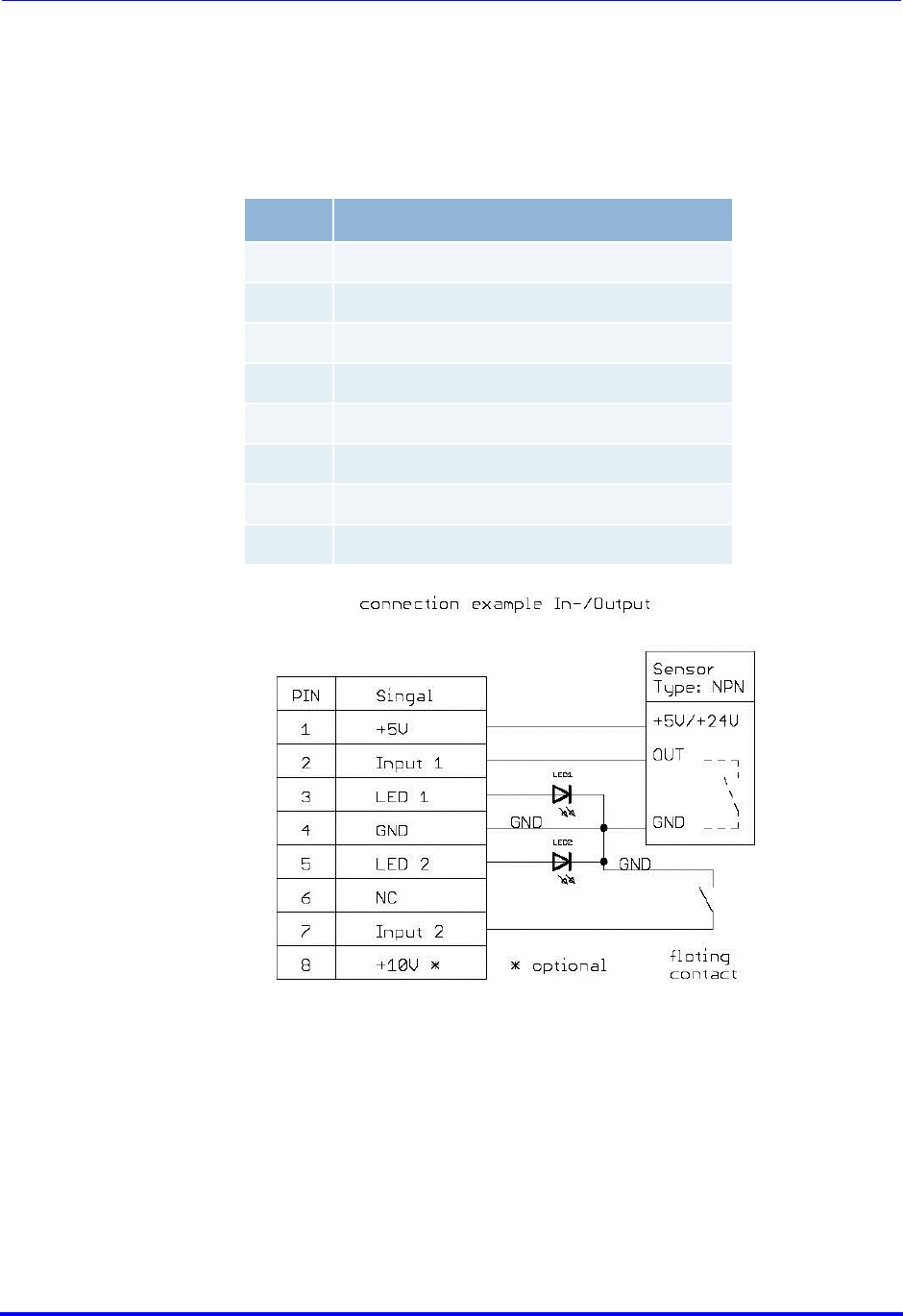
6.10 Input and Output
The port labeled Remote I/O is used for external presence sensors and an
external output like a LED for status indication. The input signal is used for
pod placement and pod removal events.
The port is a shielded RJ45 socket.
###
Pin Signal
1+ 5 V
2Input 1
3LED 1 out
4GND
5LED 2 out
6NC
7Input 2
810 V (optionally)
Brooks Automation
34 260301 Revision A
6 Installation ATR60LF RFID Reader CAN Bus
6.11 DIP Switches Product Manual
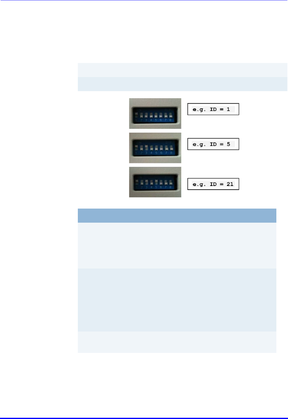
6.11 DIP Switches
The DIP switches 1 to 5 set the TargetID (0 - 31). The TargetID of the CAN
Gateway has value 0. The new TargetID is set when the reader is powered.
Switch 1 is the LSB and switch 5 is the MSB of the TargetID. A switch at ON
or Open position is 1, a switch at OFF or Close is 0.
Switch position
values:
01 - 00001
03 - 00011
10 - 01010
16 - 10000
27 - 11011
31 - 11111
Switch # 12345
Binary digit 124816
Switch # Function
6Switches between reading and writing action in test
mode.
OFF - only reading a transponder
ON - reading and writing a transponder
7Switches the reader into test mode.
In test mode, the reader reads or writes (depends on
the setting of switch 6) permanently to the transpon-
der, and shows the result via LED 'Read/Write ok' and
'Read/Write fail'.
"ON" test mode activation
8The trigger in the ON position performs an antenna
tuning cycle.
Brooks Automation
260301 Revision A 35
ATR60LF RFID Reader CAN Bus 6 Installation
Product Manual 6.12 CAN Bus Network Topology
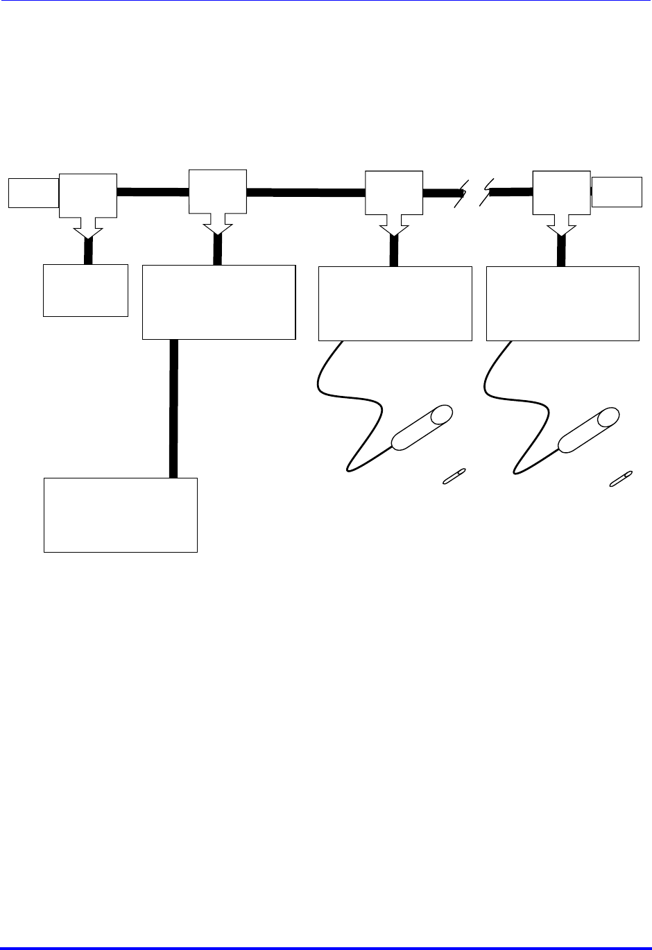
6.12 CAN Bus Network Topology
M/F Cable
9701-2915-XX
M/F Cable
9701-2915-XX
CAN Bus Gateway
GWS-33C-010 (NEW)
9701-2937-01 (EOL)
CAN Tee
9701-2935-
01
24VDC
Power
Supply
9701-2912-01
ATR9100 Reader
9701-2936-01 (EOL)
CAN Tee
9701-2935-
01
ATR60LF CAN
Reader
TLS-33C-4O00-C1-00E2 (NEW)
CAN Tee
9701-2935-
01
CAN Tee
9701-2935-
01
Terminator
9701
-2886-
01
Terminator
9701
-2886-
01
M/F Cable
9701-2915-XX
M/F Cable
9701-2915-XX
M/F Cable
9701-2915-XX
Host Computer
RS232 or Ethernet Connection
Antenna
9701-2883-04
Antenna
9701-2883-04
Transponder
RI-TRP-DR2B
Transponder
RI-TRP-DR2B
AdvanTag CAN Bus Network

Brooks Automation
36 260301 Revision A
6 Installation ATR60LF RFID Reader CAN Bus
6.12 CAN Bus Network Topology Product Manual
Brooks Automation
260301 Revision A 37
ATR60LF RFID Reader CAN Bus 7 Operation
Product Manual 7.1 Operating Personnel
7Operation
This chapter gives you an overview of the following topics:
Operating Personnel
Data Items Dictionary
Attribute (ECID and SVID) Values
Operation of the SECS Protocol
7.1 Operating Personnel
7.2 Theory of Operation
7.2.1 ATR60LF CAN Reader
The ATR60LF CAN Reader only communicate with the CAN Gateway through
CAN Bus Port. It is backwards compatible with the ATR9100 in CAN Bus
mode. It is up to 31 ATR60LF CAN Readers can connect to the ATR CAN
Gateway via a single host. The host system can address each of the
ATR60LF CAN reader via the Gateway, which makes the Gateway a
transparent system. The Communication between the ATR Gateway and the
multiplexed ATR60LF CAN Reader occurs on the CAN Bus.
CAUTION The RFID Reader ATR60LF CAN is designed to be operated by specially
trained personnel only. If you have doubts about the required
qualifications, contact Brooks.
Operating the device without special training can result in damage to the
reader and/or connected devices.

Brooks Automation
38 260301 Revision A
7 Operation ATR60LF RFID Reader CAN Bus
7.3 Data Items Dictionary Product Manual
7.3 Data Items Dictionary
This section defines the data items used in the standard SECS-II messages
and in the ASCII protocol. Some data items are for SECS communication
only and others are for ASCII communication only. Most of them are used in
both protocols.
Syntax:
Name A unique name for this data item. This name is used in
the message definitions.
Format The permitted item format code which can be used for
this standard data item. Item format codes are shown in
hex and octal. The notification “3()” indicates any of the
signed integer formats (30, 31, 32, 34).
Description A description of the data item, with the meanings of
specific values.
Where used The standard messages in which the data item appears.

Brooks Automation
260301 Revision A 39
ATR60LF RFID Reader CAN Bus 7 Operation
Product Manual 7.3 Data Items Dictionary
Identifier for an attribute for a specific type of object.
Attributes are Auto-ID configuration parameters (similar to ECIDs) and
status variables (similar to SVID).
For available attributes and their values, see data item ATTRVAL.
Where used S18F1, S18F3
Value of an attribute for a specific type of object.
See Attribute (ECID and SVID) Values.
Where used S18F2, S18F3
Group Event Report ID
01 - Material (pod/cassette) arrival event
02 - Material (pod/cassette) removal event
08 - Power-up event
Where used S18F71
ATTRID Format: 41
ATTRVAL Format: 41
CEID Format: 41

Brooks Automation
40 260301 Revision A
7 Operation ATR60LF RFID Reader CAN Bus
7.3 Data Items Dictionary Product Manual
Command Parameter Value (see description of message S18F13).
This parameter provides the command to be carried out by the target.
LEDStatus
LED state, 1 byte
0 = Off
1 = On
2 = Flash
3 - 255 = Reserved
LEDNo
LED number, 1 byte
1 = Status LED
2 = Status LED
3 = External output
4 - 9 = Reserved
OpStatus
Operation status: Maintenance or Idle
MT = Maintenance
OP = Operational/Idle
PageNo
PageNo refers to the page of the transponder.
PageNo takes values from 1 - 17.
Timeout
Timeout period, 2 bytes
Units: seconds
Range: 1 - 98
"99" has a special meaning: it specifies "always". For example, an LED is
turned on with the TIMEOUT value of 99; it will stay on until the host turns
it off or the device is reset.
Where used S18F13
Transponder data
Read or write data within the available capacity of the Auto-ID.
Foup transponder - single page ID: 8 bytes (read only)
Foup transponder - multi-page ID: depending on model number up to 120
bytes
Where used S18F6, S18F7
CPVAL Format: 41
DATA Format: 41

Brooks Automation
260301 Revision A 41
ATR60LF RFID Reader CAN Bus 7 Operation
Product Manual 7.3 Data Items Dictionary
Total bytes to be sent.
Range: 1 - 120
< DATASEG > must start with the first character "0" and be
followed by other numeric numbers. It indicates that the reading
will start from this offset up to the specified DATALENGTH.
Format code A9 is available on earlier versions of the software.
Please contact Brooks for availability of these format codes.
If DATALENGTH is present but DATASEG is not present, an error is
returned.
If both DATALENGTH and DATASEG have a length of zero, all data
is read.
To read/write pages, DATASEG ranges from "P1" - "P17" and DATA-
LENGTH ranges from 1 - 8.
Where used S18F5, F7
Used to identify the source of the requested data.
Range: 0 - 119
“0” and numeric offset: This is the byte offset (address) of the
start of specified data location to read from or write to.
If this field is zero length, DATASEG 00 is assumed.
To read/write pages, DATASEG ranges from “P1” - “P17” and DATA-
LENGTH ranges from 1 - 8.
Where used S18F5, S18F7
DATALENGTH Format: 41, A9
IMPORTANT If the field has a length of zero, all the data from the DATASEG onwards
is reported.
DATASEG Format: 41

Brooks Automation
42 260301 Revision A
7 Operation ATR60LF RFID Reader CAN Bus
7.3 Data Items Dictionary Product Manual
Equipment model number, maximum 6 bytes
Where used S18F2
SECS message block header associated with message block in error.
Where used S9F3, S9F5, S9F7, S9F9
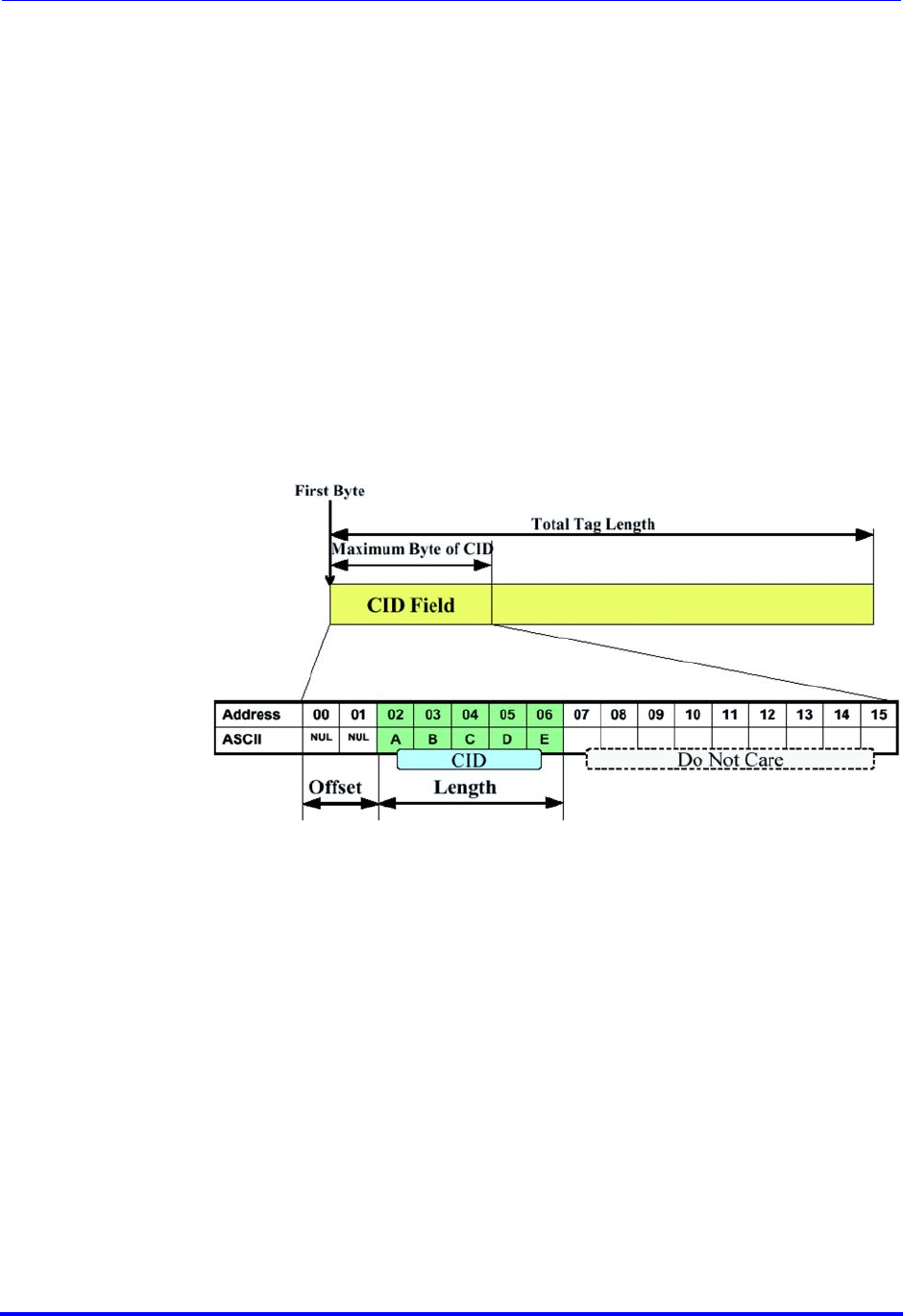
MaterialID/CarrierID is a configurable field on the reader side.
CarrierIDOffset, CarrierIDLength, CID_MAX_LENGTH determines MID.
Where used S18F10, S18F11
Software revision code, maximum 6 bytes.
Where used S1F2
SSACK acknowledge code, 2 bytes.
If there is more than one error in a message, this code represents the first
error.
NO - Normal operation
CE - Communication error, could not communicate with the transponder
TE - Transponder error, could not write to the transponder, RFN only
HE - Hardware error, cannot communicate to the RFN
EE - Execution error
If EXTENDEDSSACK is ON ( Attribute (ECID and SVID) Values), the
following error codes are also returned. However, these codes are not
defined by the SEMI standard and are manufacturer-specific.
01 - Wrong TargetID
02 - Invalid seg offset
03 - Invalid data length
04 - Data too long
05 - Data length does not match data
06 - Denied, at least one attribute does not exist
07 - Denied, at least one attribute out of range
08 - Not used
09 - Not used
10 - Could not write because transponder is locked
11 - Not used
12 - Not used
MDLN Format: 41
MHEAD Format: 21
MID (CID/CarrierID) Format: 41
SOFTREV Format: 41
SSACK Format: 41

Brooks Automation
260301 Revision A 43
ATR60LF RFID Reader CAN Bus 7 Operation
Product Manual 7.3 Data Items Dictionary
13 - Not used
14 - Subsystem command does not exist
15 - At least one parameter in the command is invalid
16 - Acknowledge, command will be performed with completion signaled
later
17 - Not used
18 - Wrong time-out value
19 - Wrong data format
20 - Not used
21 - Not used
22 - Not used
23 - Invalid transponder serial number; returned only if High Integrity is
enabled
24 - CRC error in transponder data; probable cause is multipage
transponder in
the range
25 - Could not write MID because the first page is read only
26 - Single-page transponder detected; read/write command is only
allowed for
multipage transponders
27 - More than 8 bytes MID could not be written because transponder is
single-
page. Please try writing 8 bytes only.
28 - Not used
29 - Not used
30 - Not used
31 - Not used
32 - Not used
33 - Not used
34 - Reset not allowed. Please see RESET_ENABLED (ECID table)
35 - 60 Not used
61 - Received S9F1, ASCII only. Used for SECS to ASCII conversion.
62 - Received S9F2, ASCII only. Used for SECS to ASCII conversion.
63 - Received S9F3 ASCII only. Used for SECS to ASCII conversion.
64 - Received S9F4, ASCII only. Used for SECS to ASCII conversion.
65 - Received S9F5, ASCII only. Used for SECS to ASCII conversion.
66 - Received S9F6, ASCII only. Used for SECS to ASCII conversion.
67 - Received S9F7, ASCII only. Used for SECS to ASCII conversion.
68 - Received S9F8, ASCII only. Used for SECS to ASCII conversion.
69 - Received S9F9, ASCII only. Used for SECS to ASCII conversion.
70 - Received S9F10, ASCII only. Used for SECS to ASCII conversion.
71 - Received S9F11, ASCII only. Used for SECS to ASCII conversion.
72 - Received S9F12, ASCII only. Used for SECS to ASCII conversion.
73 - Received S9F13, ASCII only. Used for SECS to ASCII conversion.
74 - Received S9F14, ASCII only. Used for SECS to ASCII conversion.
75 - 80 Not used
81 - Inter-character timeout, ASCII protocol only
82 - Inter-block timeout, ASCII protocol only
83 - Incorrect block sequence, ASCII protocol only
84 - Invalid checksum, ASCII protocol only

Brooks Automation
44 260301 Revision A
7 Operation ATR60LF RFID Reader CAN Bus
7.3 Data Items Dictionary Product Manual
85 - Invalid ASCII command, ASCII protocol only
86 - Can not communicate to the target device; Link Manager only
87 - Invalid command structure, ASCII protocol only
88 - Invalid CarrierIDOffset, CarrierIDLength
89 - Non-printable ASCII character in MID
90 - 99 Not used
Where used S18F2, S18F4, S18F6, S18F8, S18F10, S18F12
Auto-ID subsystem commands
01 - 03: Not used
04: Switch LED on device
CPVAL <LEDStatus>
<Timeout>
<LEDNo>
05 - 06: Not used
07 or PerformDiagnostics
Self Test
08 - 12: Not used
13 or Reset: Reset unit (same effect as hardware power-up of unit)
14: Not used
15 or ChangeStatus:
Change the status from Maintenance to Operating and vice versa
CPVAL M or MT = Change to maintenance
O or OP = Change to operating
GetStatus
Get Status information
CPVAL IDLE or
MANT
LOCK
Lock specified page
CPVAL <PageNo>
DefaultParams
The parameters are set to default values.
The factory settings will not change.
ADJUST Starts an automatic adjustment process of the antenna.
DefParNoNetSet Parameters are set to default values. Only the
network settings will not be reseted.
Where used S18F13
The status of UP-STREAM CONTROLLER and its associated NODEs, 1 byte.
“1” - Component added to the bus
“2” - Component removed from the bus
Where used S18F71
SSCMD Format: 41
STATUS Format: 41

Brooks Automation
260301 Revision A 45
ATR60LF RFID Reader CAN Bus 7 Operation
Product Manual 7.4 Attribute (ECID and SVID) Values
Current values of status transitions with the corresponding attributes for
CIDRW and Head (if applicable). It has the following values:
1. “PMInformation” - Preventive maintenance information
“NE” = Normal execution
“MR” = Maintenance required
2. “AlarmStatus” - Current CIDRW sub-status of ALARM STATUS
“0” = NO ALARMS
“1” = ALARMS
3. “OperationalStatus” - Current CIDRW sub-status of OPERATIONAL
“IDLE”
“BUSY”
“MANT”
4. “HeadStatus” - The current status
“IDLE”
“BUSY”
“NOOP”
Subsystem ID, 2 bytes (SEMI E99-0200A, referred to as HeadID), e.g. 00,
01, 03, 10, 11, etc.
Identifies where a request for action or data is to be applied. It is zero for
the Gateway (RS485) and non-zero for the associated subsystem
components. It can only be set using the DIP switches on the subsystem.
Where used all stream 18 messages
7.4 Attribute (ECID and SVID) Values
AlarmStatus
(Read only) Current CIDRW sub-status of ALARM STATUS
“0” = NO ALARMS
“1” = ALARMS
ASCII_T1
(ASCII only) Inter-byte timeout
2 - 100 * 0.1 s (0.2 - 10 s)
Default: 100 (10 s)
STATUSn Format: 41
TARGETID Format: 41
IMPORTANT Both 1 and 2 bytes are accepted as TargetID, but a response is always
two bytes.
Brooks Automation
46 260301 Revision A
7 Operation ATR60LF RFID Reader CAN Bus
7.4 Attribute (ECID and SVID) Values Product Manual
ASCII_T3
(ASCII only) Inter-block timeout
2 - 120 * 1 s (2 - 120 s)
Default: 45 (45 s)
BAUDRATE Specifies the communication baud rate
1 - 4,800
2 - 9,600
3 - 19,200
4 - 28,800
5 - 57,600
Default: 9,600
CarrierIDLength CarrierIDLength ranges from 1 to CID_MAX_LENGTH.
Default: 16
CarrierIDOffset CarrierIDOffset ranges from 0 to CID_MAX_LENGTH-1.
CarrierIDOffset + CarrierIDLength cannot be larger than the length of the
CID field (CID_MAX_LENGTH).
Default: 0
CHECKSUM (ASCII
only) Checksum enabled or disabled.
EN = Enabled
DI = Disabled
Default: DI
CID_DISPLAY OFF - returns MID without padding information and allows non-printable
characters in MID while reading even if CID_NP_ASCII = OFF.
ON - returns MID along with padding information
Default: ON

Brooks Automation
260301 Revision A 47
ATR60LF RFID Reader CAN Bus 7 Operation
Product Manual 7.4 Attribute (ECID and SVID) Values
CID_E99_PAD Customer has the possibility to look for padding information in MID in E99
mode. If CID_E99_PAD is set to ON the padding information will not be
filtered.
Default: OFF
CID_ERROR ON - returns an error if length of MID < CarrierIDLength
OFF - pads the MID as per the attributes CID_PAD and CID_JUSTIFY
Default: ON
CID_JUSTIFY R - MID is right-justified in MID space
L - MID is left-justified in MID space
Default: L
CID_MAX_LENGTH Takes value of (8 * N) where N = page 1 to 17
Default: 16
CID_NP_ASCII OFF - returns an error while reading/writing MID if MID contains non-
printable characters
ON - allows non-printable characters in MID while reading/writing MID
Default: OFF
CID_PAD ZERO - ASCII 0 (0x30) pads the MID
NUL - (0x00) pads the MID
Default: ZERO
Configuration (Read
only) Number of connected heads (for Gateway). In case of reader only, the
value is always 01.
01 through 31
DeviceID Messages coming from the host will be replied with the same DeviceID as
sent from the host.
0x00 - 0xFF
Default: 0xFF
DeviceType (Read
only) DeviceType is „CIDRW“.
DUAL_SENSOR At default value OFF only one sensor is defined and can be used to trigger
an automatic read.
The detection of sensor 1 will produce arrival event (S18F71) with MID of
the tag. The release of sensor 1 will produce removal event (S18F71)
without MID (zero length).
At value ON two sensors can trigger an automatic read. There is the
following behavior:
The detection of sensor 1 will produce arrival event (S18F71) with MID of
the tag. The external LED1 stays ON during read
(HOST_CONT_PORT1_LED=ON). The release of sensor 2 will produce

Brooks Automation
48 260301 Revision A
7 Operation ATR60LF RFID Reader CAN Bus
7.4 Attribute (ECID and SVID) Values Product Manual
removal event (S18F75) with MID of the tag. The external LED2 stays ON
during read (HOST_CONT_PORT1_LED=ON)
Range: ON or OFF
Default OFF
ENABLE_EVENTS Enable events (pod arrival/removal and power-up)
ON = Events are generated
OFF = Events are not generated
Default: ON
ENABLE_TIMEOUTS
(ASCII only) Enable communication timeouts.
ON = Timeout events are generated
OFF = Timeout events are not generated
Default: ON
EXTENDEDSSACK Enables the extended error codes in SSACK. The SEMI standard specifies
only five codes (NO, EE, CE, HE and TE). When this option is ON,
manufacturer-specific codes might be generated. Please see SSACK for all
error codes.
ON = All error codes are generated
OFF = Only SEMI standard error codes are generated
Default: ON
HardwareRevision-
Level Subsystem hardware revision of Gateway or reader (Head).
Up to 8 bytes
HeadID Returns the HeadID or TargetID.
Two digits
HeadStatus IDLE or MANT
HOST_CONT_PORT1
_LED If set to ON, the host can control external LED's through S18F13 command.
Range: ON or OFF
Default: OFF
HOSTNAME The network option HOSTNAME.
ASCII string of maximum 15 characters to identify the reader in a network.
Default: “ATR60LF CAN”
MANTWRITEONLY If this attribute is enabled, MID (CID) and data is read and written
according to the E99 standard.
EN = Enabled
DI = Disabled
Default: EN

Brooks Automation
260301 Revision A 49
ATR60LF RFID Reader CAN Bus 7 Operation
Product Manual 7.4 Attribute (ECID and SVID) Values
Manufacturer Returns “Brooks”
MDLN Brooks model number of Gateway or reader (Head)
Up to 6 bytes
ModelNumber See MDLN
OperationalStatus IDLE or MANT
Read only. To change the operational status use S18F13.
PARITY Parity of the serial communication port
0 = no parity
1 = even parity
2 = uneven parity
Default: 0
PIP (Read only) Pod-in-place status.
Shows whether the PIP sensor is ON or OFF.
POD_ARRIVED - PIP sensor is occupied
POD_REMOVED - PIP sensor is released
PIP_AUTOREAD Auto-read ON or OFF
ON = on
OFF = off
Default: ON
PIP_AUTOREAD_
DATA The memory type to read pod-in-place events.
Value Byte offset of DATA area or MID
Value MID, 00 - 119 (one byte less than size of available DATA area)
Default: MID
IMPORTANT This attribute should be modified with respect to
PIP_AUTOREAD_LENGTH and the size of the DATA area.

Brooks Automation
50 260301 Revision A
7 Operation ATR60LF RFID Reader CAN Bus
7.4 Attribute (ECID and SVID) Values Product Manual
PIP_AUTOREAD_
LENGTH Length of DATA to read upon pod arrival.
Value 1 - 120
Default: 16
PIP_SENSOR_
POLARITY PIP sensor polarity
HI = Active-high; when sensor goes high, a pod arrival event is generated.
LO = Active-low; when sensor goes low, a pod arrival event is generated.
Default: LO
RADIO_RETRY Configurable radio retries before returning a communication error.
Range 1 - 99
Default: 3
RDA AdvanTag returns either RD or RDA in response to the ASCII RD command.
EN = Enabled, returns RDA
DI = Disabled, returns RD
Default: EN
RW_ADJUSTMENT The ability to set the adjustment of the antenna for read and write
operations manually. If manual antenna adjustment is set, the control of
the antenna voltage is deactivated, which is used to detect a defect
antenna.
Range 0 - 7
Default: the value from the last automatic adjustment
RW_REPEATTIME If the read/write action fails, the action can be repeated after the
rw_repeattime. The number of repeats is defined by the parameter
radio_retry.
Unit 1 ms
Range 100 - 5,000
Default: 50
SELF_TEST_ RESULT Last self-test flag
IMPORTANT This is only applicable if PIP_AUTOREAD_DATA has an offset value.
IMPORTANT This attribute should be modified with respect to PIP_AUTOREAD_DATA.

Brooks Automation
260301 Revision A 51
ATR60LF RFID Reader CAN Bus 7 Operation
Product Manual 7.4 Attribute (ECID and SVID) Values
P - Pass
F - Failed
SENSOR_TIMEOUT Sensor delay after the trigger
Range 1 - 20
Unit 1 = 100 ms
Default: 01
SERIALNUM Serial number of the target device
Assigned at the factory and indicated on the label of the device, e.g.
1101MIS100001.
SerialNumber See SERIALNUM
SIGNALSTRENGTH
(Read only) Read only information RF signal strength (noise level!)
SW_PARTNUMBER Software part number
SOFTREV Subsystem software revision of Gateway or reader (head)
SoftwareRevision-
Level See SOFTREV
STATUS_ENABLE If set to Enable, Head communicates the STATUS information back to the
host.
EN = Enabled
DI = Disabled
Default: EN
TARGETID The TargetID of the device, adjustable through the DIP switches (see
HeadID)
USETESTDIP Use DIP switches 6, 7 or 8 for test mode acitvities.
Unit Bit 0 - activity of DIP switch 8 (tuning)
Bit 1 - activity of DIP switch 7 (test mode)
Bit 2 - activity of DIP switch 6 (type of test)
Bit 4 - tuning only allowed in test mode
Range 0 - 15
Default: 7

Brooks Automation
52 260301 Revision A
7 Operation ATR60LF RFID Reader CAN Bus
7.5 Operation of the SECS Protocol Product Manual
7.5 Operation of the SECS Protocol
7.5.1 Introduction
The SECS-I standard defines a communication interface that is suitable for
exchanging messages between semiconductor processing equipment and a
host. A host is a computer or network of computers that exchanges
information with the equipment to perform/execute production.
The standard does not define the data contained within a message. The
meaning of messages must be determined through a message content
standard such as SEMI Equipment Communications Standard E5 (SECS-II).
This standard provides the means for independent manufacturers to
produce equipment and hosts that can be connected without requiring
specific knowledge of each other.
The SECS-I protocol can be seen as a layered protocol used for point-to -
point communication. The layers within SECS-I are the physical link, the
block transfer protocol and the message protocol.
The standard is not intended to meet the communication needs of all
possible applications. For example, the speed of RS232 may be insufficient
to meet the needs of transferring mass amounts of data or programs in a
short period, such as may be required for high-speed functional test
applications.
In a network, the roles of host and equipment may be assumed by any
party of the network. In this situation, one end of the communications link
must assume the role of the equipment and the other the role of the host.
Electronic Industries Association Standards:
EIA RS-232-C Interface between Data Terminal Equipment and Data
Communication Equipment Employing Serial Binary Data Interchange.
7.5.2 SECS-I Implementation
This message set describes the communication between a SECS-I reader
and a host. The host and the RFID reader communicate via an RS232
interface (SECS-I).
Character structure Data is transmitted or received in a serial bit stream of 10 bits per
character at one of the specified data rates. The standard character has one
start bit (0), 8 data bits and one stop bit (1). All bit transmissions are of the
same duration.
SECS-I performs no parity or other verification of the individual bytes.
Master-Slave The host connects to the reader. If there is a conflict, the host “gives in”
(i.e. receives before sending).
In the course of communication, the reader takes on the role of the master
and the host takes on the role of the slave.

Brooks Automation
260301 Revision A 53
ATR60LF RFID Reader CAN Bus 7 Operation
Product Manual 7.5 Operation of the SECS Protocol
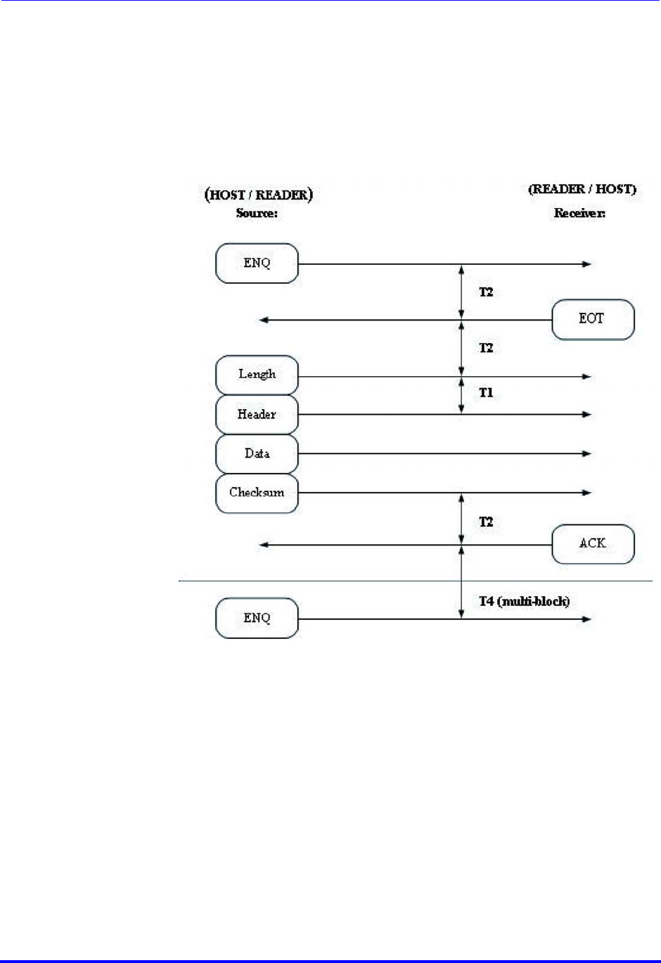
Control characters The four standard handshake codes used in the block transfer protocol are
displayed in the table below.
Message block
structure SECS message blocks have the following form:
The operation of all communication functions above the block transfer
protocol is linked in information contained in a 10-byte data element, called
the header.
The header is always the first 10 bytes of every block sent by the block
transfer protocol.
The length includes all bytes sent after the length byte, excluding the two
checksum bytes. The maximum block length allowed by SECS-I is 254
bytes and the minimum is 10 bytes.
<ENQ> 0x05 Request to send
<EOT> 0x04 Ready to receive
<ACK> 0x06 Correct reception
<NAK> 0x15 Incorrect reception
Byte ms
bDescription
Length 0Length without checksum, 10 - 254
Header
1 R Upper device ID
2Lower device ID
3 W Upper message ID (Stream)
4Lower message ID (Function)
5 E Upper block number
6Lower block number
System
bytes
7System byte 1
8System byte 2
9System byte 3
10 System byte 4
Text 11 - 254 Message text, user data
Checksum 255, 256 16-bit unsigned checksum

Brooks Automation
54 260301 Revision A
7 Operation ATR60LF RFID Reader CAN Bus
7.5 Operation of the SECS Protocol Product Manual
The reverse bit (R bit) signifies the direction of a message. The R-bit
(msb) is set to 0 for messages to the equipment and to 1 for messages to
the host.
The W bit indicates that the sender of a primary message expects a reply. A
value of 1 in the W bit means that a reply is expected.
The message ID identifies the format and content of the message being
sent.
A primary message is defined as any odd-numbered message.
A secondary message is defined as any even-numbered message.
The end bit determines whether a block is the last block of the message. A
value of 1 means that the block is the last block.
A message sent as more than one block is called a multi-block message.
A block number of 1 is given to the first block, and the block number is
incremented by one for each subsequent block until the entire message is
sent.
As all messages can be sent in one block, the block number always has the
value 1.
The system bytes in the header of each message for a given device ID
must meet the following requirements:
The system bytes of a primary message must be distinct from the
bytes of all currently open transactions initiated from the same
end of the communications link.
The system bytes of the reply message are required to be the
same as the system bytes of the corresponding primary message.
The system bytes are incremented for each primary message.
The checksum is calculated as the numeric sum of the unsigned binary
values of all the bytes, after the length byte and before the checksum and
in a single block.
Brooks Automation
260301 Revision A 55
ATR60LF RFID Reader CAN Bus 7 Operation
Product Manual 7.5 Operation of the SECS Protocol
Block transfer
protocol The drawing below illustrates some simple message interactions between
the host and the equipment. The figure shows the possible handshake
sequence to acquire the status of the equipment.
When the host wants to send, it first sends an <ENQ> and then tries to
read.
If it receives an <EOT>, it sends its message and then expects an <ACK>.
If it receives an <ENQ>, it puts off sending its message, sends an <EOT>
and then reads the other message.
When both the host and the equipment try to send at the same time, the
host must cancel its inquiry, because the host is working in slave mode. It
must first receive the equipment message, because the reader is the
master. Only then can the host send its message.
For more detailed information about all possible cases, see SEMI E4.
(SEMI Equipment Communication Standard 1 Message Transfer SECS-I)
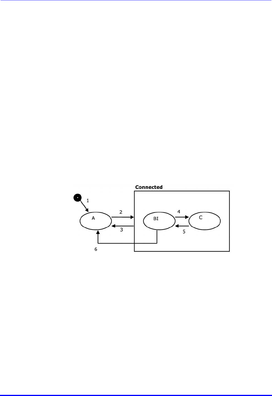
Brooks Automation
56 260301 Revision A
7 Operation ATR60LF RFID Reader CAN Bus
7.5 Operation of the SECS Protocol Product Manual
7.5.3 HSMS Option
The hardware version with an Ethernet interface uses the HSMS protocol. It
works as a HSMS server. That means that it waits for a connection inquiry
of any HOST PC.
TCP/IP: IP address xxx.xxx.xxx.xxx Port 3241
If a connection inquiry of any HOST takes place, the reader initializes the
HSMS connection, and the SECS-II messages defined in the message set
are forwarded from the reader to the respective HOST and vice versa.
It is possible to operate all readers connected to the network via one or
several HOST PCs.
But one HSMS reader can only be connected to one HOST at a time.
Use the Brooks Device Discoverer to change the TCP/IP settings.
7.5.4 HSMS Implementation
HSMS defines the procedure for all message exchanges between entities
across the TCP/IP. The HSMS Connection Status Diagram - The HSMS
status machine is illustrated in the diagram below. The behavior described
in this diagram defines the basic requirements of HSMS:
A - NOT CONNECTED
The entity is ready to listen for or to initiate TCP/IP connections, but either
has not yet established any connections or all previously established TCP/IP
connections have been terminated.
CONNECTED
A TCP/IP connection has been established. This status has two sub-
statuses, NOT SELECTED and SELECTED.
B - NOT SELECTED
A sub-status of CONNECTED in which no HSMS session has been
established or any previously established HSMS sessions have ended.

Brooks Automation
260301 Revision A 57
ATR60LF RFID Reader CAN Bus 7 Operation
Product Manual 7.5 Operation of the SECS Protocol
C - SELECTED
A sub-status of CONNECTED in which at least one HSMS session has been
established. This is the normal “operating” status of HSMS: data messages
may be exchanged in this status.
The specification of a required TCP Application Program Interface (API) for
use in implementations is outside the scope of HSMS. An HSMS
implementation may use any TCP/IP API sockets, TLI (Transport Layer
Interface), etc.
#Current
status Trigger New
status Comment
1... Local entity-specific
preparation for TCP/
IP communication
Not
connected Action depends on connection
procedure to be used: active or
passive.
2Not connected A TCP/IP connection
is established for
HSMS
communication.
Connected -
Not selected None
3Connected Breaking of TCP
connection Not
connected HSMS only permits termination of
the connection when the connection
is in the Not selected sub-status.
4Not selected Successful
completion of HSMS
Select procedure.
Selected HSMS communication is now fully
established: data message
exchange is permitted.
5Selected Successful
completion of HSMS
Deselect or Separate.
Not selected This transition normally indicates
the end of HSMS communication;
an entity would immediately
proceed to break the TCP/IP
connection.
6Not selected T7 connection
timeout Not
connected There is a time limit on how long an
entity is required to remain in the
Not selected status before either
entering in Selected status or
returning to Not connected status.
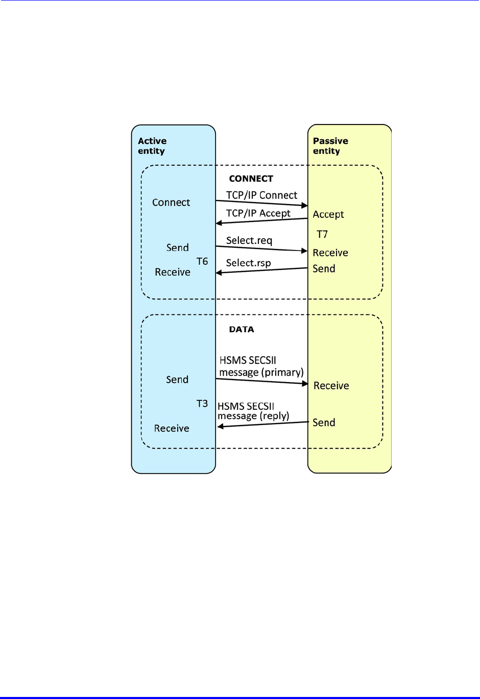
Brooks Automation
58 260301 Revision A
7 Operation ATR60LF RFID Reader CAN Bus
7.5 Operation of the SECS Protocol Product Manual
HSMS message
exchange procedures HSMS defines the procedures for all message exchanges between entities
across the TCP/IP connection established according to the procedures in the
previous section. As explained in the overview, once the connection is
established, the two entities establish HSMS communications with the
Select procedure. The data messages may be exchanged in any direction at
any time. When the entities wish to end HSMS communication, the Deselect
or Separate procedure is used to terminate the HSMS communication.
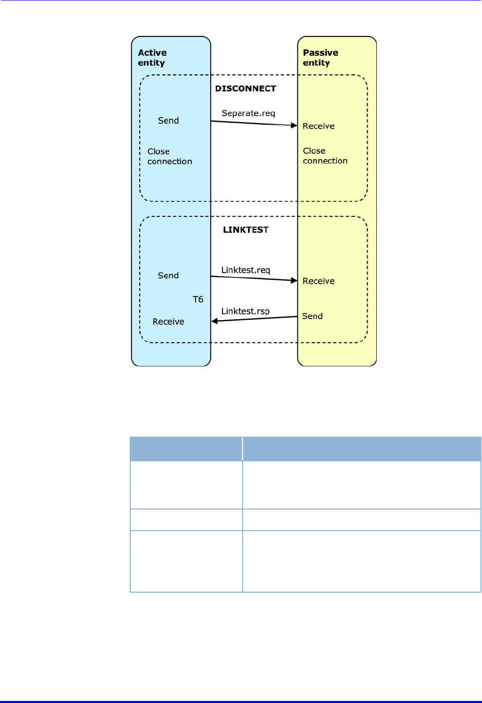
Brooks Automation
260301 Revision A 59
ATR60LF RFID Reader CAN Bus 7 Operation
Product Manual 7.5 Operation of the SECS Protocol
HSMS message
format This section defines the detailed format of the messages used by the
procedures in the previous section. An HSMS message is transmitted as a
single continuous stream of bytes in the following order:
The minimum possible message length is 10 (header only).
The maximum possible message length depends on SECS-I.
Number of bytes Description
4 bytes Message length. MSB first. Specifies the
number of bytes in the message header plus
the message text.
10 bytes Message header
0 - n bytes Message text. Format is further specified by P-
type field of message header. The message text
corresponds to message data by SECS-II
encoding.

Brooks Automation
60 260301 Revision A
7 Operation ATR60LF RFID Reader CAN Bus
7.5 Operation of the SECS Protocol Product Manual
HSMS message
header The message header is a 10-byte field. The bytes in the header are
numbered from byte 0 (first byte transmitted) to byte 9. The format of the
message header is as follows:
The physical byte order is designed to correspond as closely as possible to
the SECS-I header.
The session ID is a 16-bit unsigned integer value, which occupies bytes 0
and 1 of the header (byte 0 is MSB). Its purpose is to provide an
association by reference between control messages and subsequent
messages.
Header byte 2 is used in different ways for different HSMS messages. For
control messages, it contains 0 or a status code. For a data message, it
contains the W bit and SECS stream.
Header byte 3 contains 0 or a status code for control messages. For data
messages, it contains the SECS function.
P-type is an 8-bit unsigned integer value which occupies byte 4 of the
message header; message header and message text are encoded. Only P-
type = 0 is defined by HSMS to mean SECS-II message encoding. For non-
zero P-type values, see SEMI E37.
S-type (session type) is a 1-byte unsigned integer value which occupies
header byte 5.
Bytes Description
0-1 Session ID (Device ID)
2Header byte 2
3Header byte 3
4P-type
5S-type
6-9 System bytes
Value Description
0SECS-II Encoding
1 - 127 Reserved for subsidiary standards
128 -
255 Reserved, not used

Brooks Automation
260301 Revision A 61
ATR60LF RFID Reader CAN Bus 7 Operation
Product Manual 7.5 Operation of the SECS Protocol
The system bytes are used to uniquely identify a transaction among the set
of open transactions. The system bytes are also defined as SECS-I-specific.
HSMS message
format summary
* Indicates further specification by subsidiary standards
Value Description Value Description
0Data message 6Linktest.rsp
1Select.req 7Reject.req
2Select.rsp 8Not used
3Deselect.req 9Separate.req
4Deselect.req 10 Not used
5Linktest.req 11-255 Reserved, not used
Message header
Message type bytes 0 - 1
Session ID byte 2 byte 3 byte 4
P-type
byte 5
S-type
bytes 6 - 9
System bytes Message
text
Data
message *
(no R bit)
W bit and
SECS
stream
SECS
Function 0 0 Primary:
Unique Reply:
Same as
primary
Text
Select req * 0 0 0 1 Unique None
Select.rsp Same
as.req 0Select
status 0 2 Same as.req None
Deselect.req * 0 0 0 3 Unique None
Deselect.rsp Same
as.req 0Deselect
Status 0 4 Same as.req None
Linktest.req 0xFFFF 0 0 0 5 Unique None
Linktest.rsp 0xFFFF 0 0 0 6 Same as.req None
Reject.req Same as
message
being
rejected
P-type or
S-type of
message
being
rejected
Reason
code 0 7 Same as
message being
rejected
None
Separate.req * 0 0 0 9 Unique None

Brooks Automation
62 260301 Revision A
7 Operation ATR60LF RFID Reader CAN Bus
7.5 Operation of the SECS Protocol Product Manual
7.5.5 SECS-II Implementation
Introduction The SEMI Equipment Communication Standard Part 2 (SECS-II) defines
how messages exchanged between intelligent equipment and a host are
interpreted.
It is the intent of this standard to be fully compatible with SEMI Equipment
Communication Standard E4 (SECS-I).
The messages defined in this specification support the typical activities
required for the BROOKS RFID reader.
SECS-II gives form and meaning to messages exchanged between the
equipment and the host using a message transfer protocol, such as SECS-I.
SECS-II defines the method of conveying information between the
equipment and the host in the form of messages.
These messages are organized into categories of activities, called streams,
which contain specific messages, called functions. In SECS-II, messages
are identified by a stream code (0-127, 7 bits) and a function code (0-255,
8 bits). Each combination of stream and function represents a unique
message identification.
SECS-II defines the structure of messages into entities called items and
lists of items. These data structures define the logical divisions of the
message as distinct from the physical division of the message transfer
protocol.
An item is an information packet that has a length and format defined by
the first 2, 3 or 4 bytes of the item. These bytes are called the item header.
The item header consists of the format byte and the length byte as shown
below.
A list is an ordered set of elements, whereby an element can be either an
item or a list. The list header has the same form as an item header with
Byte Name Description
0Format and
number of
the length
bytes
The data format is coded in the upper
6 bits.
The two less significant bits determine
the number of the following length
bytes.
1
1-2
1-3
Length bytes The length corresponds to the number
of the bytes of a data element. In the
"List" format, the length corresponds to
the number of the list elements.
The standard does not require the
minimum possible number of length
bytes for a given data length.
Next
<Length> Data Data bytes of a data element or
number of the data elements in case of
the "List" format.

Brooks Automation
260301 Revision A 63
ATR60LF RFID Reader CAN Bus 7 Operation
Product Manual 7.5 Operation of the SECS Protocol
format type 0. However, the length byte refers to the number of elements
in the list rather than to the number of bytes.
Data items The formats represent arrays of types: <type>[number of elements],
whereby <type> is one of the following:
Oct-
code Hex-
code Forma
tMeaning Example
00 01 List List element with the
number of the
“Length” data
elements
<L2>
<A “Hello”>
<B 0x00>
11 25 Boolean 1-byte Boolean
false = 00
true = 01 <Boolean1 0x00>
10 21 Binary Byte sequence
of the length “Length” <B1 0x01>
20 41 ASCII Printable ASCII
characters <A “Hello”>
31 65 I1 1-byte signed integer <I1 123>
32 69 I2 2-byte signed integer <I2 -12345>
34 71 I4 4-byte signed integer <I4 2147483647>
30 61 I8 8-byte signed integer <I8
931372980293834>
51 A5 U1 1-byte unsigned
integer <U1 0>
52 A9 U2 2-byte unsigned
integer <U2 #empty>
54 B1 U4 4-byte unsigned
integer <U4 429489725>
50 A1 U8 8-byte unsigned
integer <U8
763468676756767>
40 91 F8 8-byte floating point <F8 1.223 e204>
44 81 F4 4-byte floating point <F4 -1.23 >

Brooks Automation
64 260301 Revision A
7 Operation ATR60LF RFID Reader CAN Bus
7.5 Operation of the SECS Protocol Product Manual
Data item examples
Message set The SECS-II message set used by the LF60C SoliD Gen3 reader consists of
the following different stream types.
Stream 1: (Equipment status)
S1F1 and S1F2 Are you there request
Stream 9: (System errors)
S9F1 Unrecognized device ID (UDN)
S9F3 Unrecognized stream type (USN)
S9F5 Unrecognized function type (UFN)
S9F7 Illegal data (IDN)
S9F9 Transaction timer timeout (TTN)
According to SEMI E99 carrier ID read/writer functional standard for SECS-
I and SECS-II protocol, the RFID Reader LF60C SoliD Gen3 supports these
defined stream 18 messages:
Stream 18: (Equipment status)
S18F1 Read attribute request (RAR)
S18F3 Write attribute request (WAR)
S18F5 Read data request (RDR)
S18F7 Write data request (WDR)
S18F9 Read material ID request (RMID)
S18F11 Write material ID request (WMID)
S18F13 Subsystem command request (SCR)
S18F71 Event report send (ERS)
S18F79 Read STATUS request (STATE)
Meaning Format Length
1-byte integer 65 01 xx
4-byte integer 71 04 MSB ... ... LSB
ASCII 41 06 1st chr 2nd chr 3rd chr 4th chr 5th chr 6th chr
Zero-length xx 00
List data item 01 03 1st element 2nd element 3rd element
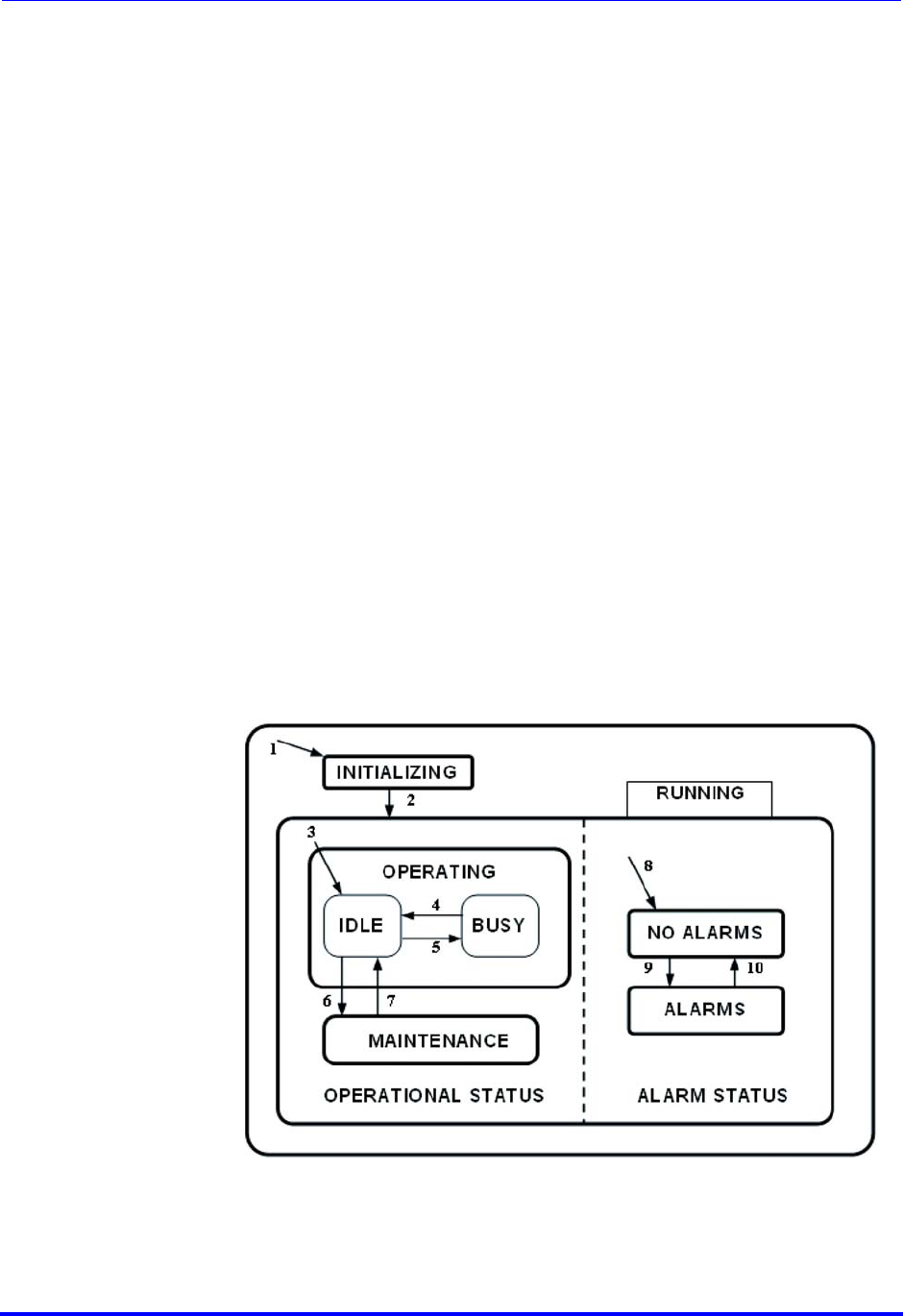
Brooks Automation
260301 Revision A 65
ATR60LF RFID Reader CAN Bus 7 Operation
Product Manual 7.5 Operation of the SECS Protocol
7.5.6 SEMI E99
Introduction The purpose of the Carrier ID reader/writer functional standard is to
provide a common specification for concepts, behavior and services
provided by a carrier ID reader/writer to an upstream controller. A standard
interface increases the interchangeability of a carrier ID reader/writer, so
that users and equipment suppliers have a wide choice.
Scope:
The interface standard addresses the functional requirements for a
generic carrier ID reader/writer interface with an upstream
controller.
The specification includes the required behavior and required
communications for a carrier ID reader and writer.
The specification does not require, define or prohibit asynchronous
messages sent by the carrier ID reader or writer.
This standard does not purport to address safety issues, if any,
associated with its use.
Status models To facilitate independent control of the individual heads, there are two
separate status models defined, one for the CIDRW subsystem and one for
each individual head. The BROOKS reader combines the CIDRW subsystem
with the head.
The status model for the BROOKS reader is displayed in the status model
below.

Brooks Automation
66 260301 Revision A
7 Operation ATR60LF RFID Reader CAN Bus
7.5 Operation of the SECS Protocol Product Manual
The table below defines the status of the BROOKS RFID reader.
Status Definition
ALARM
STATUS Displays the presence or absence of alarms.
ALARMS An alarm condition exists.
BUSY A service is being performed that affects the status of the
hardware.
CIDRW Super-status of the CIDRW status model. Always active
when the CIDRW is powered on.
IDLE No service is being performed. All heads are idle.
INITIALIZING The CIDRW is carrying out initialization and a self-
diagnostic. Presence or absence of alarms is initially
determined in this status.
NO ALARMS No alarm condition exists.
OPERATING Normal operating status where reading and/or writing
operations can be performed.
OPERATING
STATUS The CIDRW is fully capable of performing all services that
it supports.
RUNNING The CIDRW is operational and able to communicate.
MAINTENANC
EInternal setup and maintenance activities.

Brooks Automation
260301 Revision A 67
ATR60LF RFID Reader CAN Bus 7 Operation
Product Manual 7.5 Operation of the SECS Protocol
The table below defines the transitions of the BROOKS SECS-I status model
of the RFID reader.
Valid services per
status The following table shows which of the various services can be performed
by the reader when the reader is in various individual statuses.
#Previous
state Trigger New
status Action Comment
1Any Power-up or reset INITIALIZ-
ING Initialize hard-
ware and soft-
ware
Default entry on power-up
2INITIALIZ-
ING Initialization is com-
plete. RUNNING None The CIDRW is now able to
communicate.
3INITIALIZ-
ING Default entry into
OPERATING IDLE None Internal
4IDLE A service request to
read or write or per-
form diagnostics is
received.
BUSY None
5BUSY All services request
that effect the state
of the hardware are
completed
IDLE None
6IDLE A user selects the
MAINTENANCE sta-
tus and all heads are
IDLE.
MAINTE-
NANCE None The upstream controller may
send a request or the opera-
tor may set a switch to select
the MAINTENANCE status.
Maintenance and setup activ-
ities may now be performed.
7MAINTE-
NANCE A user selects the
OPERATING status
and all heads are
IDLE
IDLE None The upstream controller may
send a request or the opera-
tor may set a switch to select
the OPERATING status. Nor-
mal operating activities may
now be performed.
8INITIALIZ-
ING Default entry into
ALARM STATUS ALARMS or
NO ALARMS None
9NO ALARMS An alarm condition is
detected. ALARMS None
10 ALARMS All alarm conditions
have cleared. NO ALARMS None
11 Any A reset service
request is received. CIDRW None

Brooks Automation
68 260301 Revision A
7 Operation ATR60LF RFID Reader CAN Bus
7.5 Operation of the SECS Protocol Product Manual
Service
Write ID
Write data
Set attributes
Reset
Read ID
Read data
Perform diag.
Get status
Get attributes
Change status
Reader status
INIT
IDLE/BUSY X X X X X X X X X
MANT X X X X X X X X
IMPORTANT Note that the CIDRW may not be able to communicate when in
initializing status after power-up or reset service.

Brooks Automation
260301 Revision A 69
ATR60LF RFID Reader CAN Bus 7 Operation
Product Manual 7.5 Operation of the SECS Protocol
7.5.7 Message Details
Equipment status S1F1: ARE YOU THERE REQUEST (R) H -> E
This message is used to perform a heartbeat between host and connected
device.
S1F1 W . * Header only
S1F2: ON-LINE DATA (D) E -> H
The device signifies that it is online and reports the model number and the
software revision of the head.
S1F2
<L[2]
<MDLN >
<SOFTREV >
>
System errors S9F1: UNRECOGNIZED DEVICE ID (E -> H)
The device ID in the message block header does not correspond to the
equipment device ID.
S9F1
<MHEAD > .
S9F3: UNRECOGNIZED STREAM TYPE (E -> H)
The reader does not recognize the stream type in the message block
header.
S9F3
<B[10] MHEAD > .
S9F5: UNRECOGNIZED FUNCTION TYPE (E -> H)
The reader does not recognize the function number in the message block
header.
S9F5
<B[10] MHEAD > .
S9F7: ILLEGAL DATA (E -> H)
The reader does not recognize the data in the message.
S9F7
<B[10] MHEAD > .

Brooks Automation
70 260301 Revision A
7 Operation ATR60LF RFID Reader CAN Bus
7.5 Operation of the SECS Protocol Product Manual
S9F9: TRANSACTION TIMER TIMEOUT (E -> H)
This message indicates that a transaction timer has timed out and that the
corresponding transaction was aborted. Only the last sent message (which
must be confirmed by the host) is stored and controlled.
S9F9
<B[10] SHEAD > .
Subsystem control
and data S18F1: READ ATTRIBUTE REQUEST (RAR) (H -> E)
This message requests the current values of specific attributes of the
subsystem component indicated in the TARGETID.
S18F1 W
L,2
<TARGETID>
L,n <ATTRID1>
…
<ATTRIDn>
S18F2: READ ATTRIBUTE DATA (RAD) (E -> H)
This message returns the current values of the requested attributes and the
current status of the requested component indicated in the TARGETID.
S18F2
L,4 <TARGETID>
<SSACK>
L,n <ATTRVAL1>
…
<ATTRVALn>
L,s
<STATUS1>
…
<STATUSs>
If the ATTRID of the S18F1 message is unknown, the corresponding
ATTRVAL has the value <nothing>.

Brooks Automation
260301 Revision A 71
ATR60LF RFID Reader CAN Bus 7 Operation
Product Manual 7.5 Operation of the SECS Protocol
Exceptions:
If the attribute list is empty (L,0), the following 10 attributes are returned
in the order specified bellow:
Configuration
AlarmStatus
OperationalStatus
HeadStatus
HeadID
HardwareRevisionLevel
Manufacturer
ModelNumber
SoftwareRevisionLevel
SerialNumber
If the TargetID is invalid, no statuses are sent (list of zero).
S18F3: WRITE ATTRIBUTE REQUEST (WAR) (H -> E)
This message requests the subsystem to set the value of the read/write
attributes of the component specified in the TARGETID.
S18F3 is a transactional message, i.e. either all attributes will
be set at once or none.
S18F3 ,W
L,2
<TARGETID>
L,2 <ATTRID1>
<ATTRVAL1>
L,2 <ATTRIDn>
<ATTRVALn>

Brooks Automation
72 260301 Revision A
7 Operation ATR60LF RFID Reader CAN Bus
7.5 Operation of the SECS Protocol Product Manual
S18F4: WRITE ATTRIBUTE ACKNOWLEDGE (WAA) (E -> H)
This message acknowledges the success or reports the error of the request
to write attribute data to the subsystem indicated in the TARGETID.
S18F4 L,3
<TARGETID>
<SSACK>
L,1
L,s <STATUS1>
…
<STATUSs>
If the ATTRID of the S18F3 message is unknown, a communication error
(CE) occurs.
S18F5: READ DATA REQUEST (RDR) (H -> E)
The host requests the subsystem indicated in the TARGETID to read
information. DATASEG may be used to indicate a specific section of data to
be read. DATA-LENGTH is used to limit the amount of data for that section.
S18F5 W
L,3
<TARGETID>
<DATASEG>
<DATALENGTH>
If DATASEG and DATALENGTH are both omitted (zero length items), up to
200 bytes of the data area are requested. If only DATALENGTH is omitted,
all data within the indicated section is requested.
S18F6: READ DATA (RD) (E -> H)
This message is used to return requested information from the subsystem
indicated in the TARGETID or to acknowledge the result of the request.
S18F6 L,3
<TARGETID>
<SSACK>
<DATA>
If the TARGETID is unknown, a communication error (CE) occurs.

Brooks Automation
260301 Revision A 73
ATR60LF RFID Reader CAN Bus 7 Operation
Product Manual 7.5 Operation of the SECS Protocol
S18F7: WRITE DATA REQUEST (WDR) (H ->E)
This message requests to write data to the subsystem component indicated
in the TARGETID. DATASEG may be used to indicate a specific section of the
data area to be written or overwritten.
S18F7 W
L,4
<TARGETID>
<DATASEG>
<DATALENGTH
<DATA>
If DATASEG and DATALENGTH are both omitted (zero length items), up to
200 bytes in the data area are to be overwritten. If only DATALENGTH is
omitted or if DATALENGTH has a value of zero, then all data within the
indicated section is to be written.
If DATASEG is omitted (zero length items), the value of DATALENGTH sets
the length of data that is to be written. If the length of the data that is to be
written is longer than the value of DATALENGTH, a communication error
(CE) occurs.
S18F8: WRITE DATA ACKNOWLEDGE (WDA) (E -> H)
This message acknowledges the success or failure of writing data to the
subsystem indicated in the TARGETID.
S18F8 L,3
<TARGETID>
<SSACK>
L,s <STATUS1>
…
<STATUSs>
If the TARGETID is unknown, a communication error (CE) occurs.
Exceptions:
This command is not allowed for single-page TIRIS transponders.
If the TargetID is invalid, no statuses are sent (list of zero).

Brooks Automation
74 260301 Revision A
7 Operation ATR60LF RFID Reader CAN Bus
7.5 Operation of the SECS Protocol Product Manual
S18F9: READ ID REQUEST (RMID) (H -> E)
This message is used to request the subsystem indicated by the TARGETID
to read the MID.
S18F9,W
<TARGETID>
S18F10: READ ID DATA (MID) (E -> H)
This message returns a requested material identifier MID as read by the
subsystem indicated in the TARGETID.
S18F10
L,4 <TARGETID>
<SSACK>
<MID>
L,s
<STATUS1>
…
<STATUSs>
Exceptions:
If the TargetID is invalid, no statuses are sent (list of zero).

Brooks Automation
260301 Revision A 75
ATR60LF RFID Reader CAN Bus 7 Operation
Product Manual 7.5 Operation of the SECS Protocol
S18F11: WRITE MATERIAL ID REQUEST (WMID) (H -> E)
This message is used to request the subsystem indicated by the TARGETID
to write the MID.
S18F11 W
L,2
<TARGETID>
<MID>
S18F12: WRITE ID ACKNOWLEDGE (WIA) (E -> H)
This message acknowledges the success or error of writing the MID to the
subsystem indicated in the TARGETID.
S18F12
L,3 <TARGETID>
<SSACK>
L,s
<STATUS1>
…
<STATUSs>
If the TARGETID is unknown, a communication error (CE) occurs.
Exceptions:
For single-page TIRIS transponders, only 8 bytes are written.
If this command fails, some or all of the previous data in the
transponder might be lost. Read the transponder to confirm the
contents of the transponder.
If the TargetID is invalid, no statuses are sent (list of zero).
ATTENTION The reader must be in the maintenance mode to write the MID with
message S18F11.
ATTENTION If the length of the MID is longer than what the subsystem can accept,
the subsystem will return a failure message in the reply SSACK. If the
length of the MID is less than the maximum allowed length of device,
then the MID will be padded with “0” in the front. Refer to MicroTag
READ/WRITE OPERATION in this document.

Brooks Automation
76 260301 Revision A
7 Operation ATR60LF RFID Reader CAN Bus
7.5 Operation of the SECS Protocol Product Manual
S18F13: SUBSYSTEM COMMAND REQUEST (SCR) (H -> E)
This message is used to request the subsystem indicated in the TARGETID
to perform a specific action.
S18F13 W
L,3
<TARGETID>
<SSCMD>
L,n
<CPVAL>
…
<CPVALn>
SSCMD 04:
Flashing LED on node/device
L,3
<TargetID>
<04>
L,3 <LEDSTATE> /* On, off, or flashing */
<TIMEOUTTIMEOUT> /* Number of seconds */
<LEDNO> /* The LED number: 1, 2, etc */
SSCMD 07 or PerformDiagnostics:
Initiate self test
L,3
<TargetID>
<07> or <PerformDiagnostics>
L,0
SSCMD 13 or Reset:
Reset unit
L,3
<TargetID>
<13> or <Reset>
L,0
SSCMD 15 or ChangeState:
Change the operating state.
L,3
<TargetID>
<15> or <ChangeState>
L,1
<OpState> (MT or OP)

Brooks Automation
260301 Revision A 77
ATR60LF RFID Reader CAN Bus 7 Operation
Product Manual 7.5 Operation of the SECS Protocol
SSCMD GetStatus:
Get status
L,3
<TargetID>
<GetStatus>
L,0
SSCMD LOCK: (future development)
Lock specified page
L,3
<TargetID>
<LOCK>
L,1
<PageNo>
S18F14: SUBSYSTEM COMMAND ACKNOWLEDGE (SCA) (H -> E)
This message reports the result from the subsystem specified in the
TARGETID for the requested action.
S18F14 L,3
<TARGETID>
<SSACK>
L,s
<STATUS1>
…
<STATUSs>
If the TARGETID is unknown, a communication error (CE) occurs.
Exceptions:
If the TargetID is invalid, no statuses are sent (list of zero).

Brooks Automation
78 260301 Revision A
7 Operation ATR60LF RFID Reader CAN Bus
7.5 Operation of the SECS Protocol Product Manual
S18F71: EVENT REPORT SEND (ERS) (E -> H)
Events are sent to the host using this command.
The format is as follows:
L,4
<TargetID>
<SSACK>
<CEID>
L,n
<DVNAME1>
<DVVAL1>
<DVNAMEn >
<DVVALn >
Response:
There is no primary or secondary response expected from the host, except
the normal SECS-1 ACK for the receipt of the block.
Note:
To eliminate false or spurious events, the pod arrival/removal events are
filtered. Once a change has been detected (an arrival or removal), the next
change will not be registered for 1.5 to 2 seconds.
CEID: 01 - Material (pod/cassette) arrival event:
L,4
<TargetID>
<SSACK>
<01> * CEID
L,2
"AutoReadData"
<Data> /* If auto read, then data. Otherwise null string */
CEID: 02 - Material (pod/cassette) removal event:
L,4
<TargetID>
<SSACK>
<02> * CEID
L,0
CEID: 08 - RFN power-up event:
L,4
<TargetID>
<SSACK>
<08> * CEID
L,0

Brooks Automation
260301 Revision A 79
ATR60LF RFID Reader CAN Bus 7 Operation
Product Manual 7.5 Operation of the SECS Protocol
S18F75: EVENT REPORT SEND SENSOR2 (E -> H)
If the second sensor is available and activated (parameter
DUAL_SENSOR=ON) than the events from this sensor will be shown by the
function S18F75.
Response:
There is no primary or secondary response expected from the host, except
the normal SECS-1 ACK for the receipt of the block.
Note:
At dual sensor mode only the removal event from the second sensor will be
displayed with automatic read data.
CEID: 02 - Material (pod/cassette) removal event:
S18F75
L,4
<TargetID>
<SSACK>
<02> * CEID
L,2
„AutoReadData“
<Data> / *If auto read ...
S18F79: READ STATE REQUEST (STATE) (H -> E)
Query the CIDRW state of the transition model.
S18F79,W
<TargetID>
S18F80: TRANSITION STATE (State) (E -> H)
This message returns the current state of the transition model.
S18F80 L,3
<TARGETID>
<SSACK>
<STATUS> (IDLE, BUSY, ALARMS or MAINTENANCE)

Brooks Automation
80 260301 Revision A
7 Operation ATR60LF RFID Reader CAN Bus
7.5 Operation of the SECS Protocol Product Manual

Brooks Automation
260301 Revision A 81
ATR60LF RFID Reader CAN Bus 8 Service and Troubleshooting
Product Manual 8.1 General
8 Service and Troubleshooting
This chapter gives you an overview of the following topics:
General
Qualified Troubleshooting Personnel
Safety Instructions
Error Codes
Error Display with LED
Reader Does Not Respond
Reset
Power Cut
Software Releases
Customer Service
8.1 General
Follow the Instructions Specified in the Safety Chapter
Follow the general safety information in the chapter Safety
Instructions.
The RFID reader and its components must be serviced by
Brooks only!
If errors occur, follow the instructions in this section. Do not
carry out any error eliminating measures other than the ones
described in this section!
If you are uncertain about errors and their handling, contact
Brooks Product Support, see Customer Service. Have the
serial number of the RFID reader ready as shown on the label
(see Device Label) when contacting Brooks Product
Support!
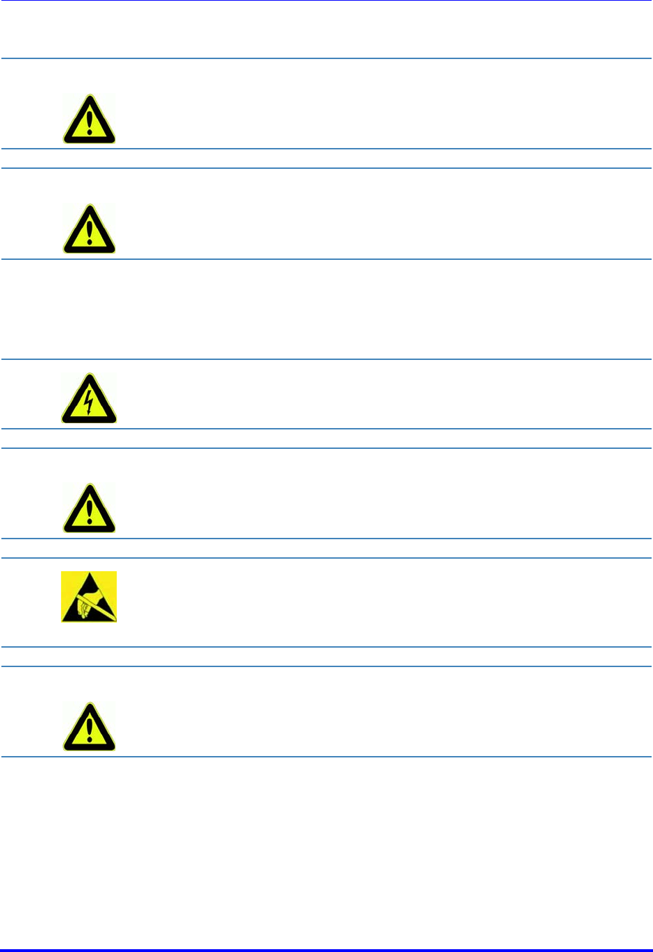
Brooks Automation
82 260301 Revision A
8 Service and Troubleshooting ATR60LF RFID Reader CAN Bus
8.2 Qualified Troubleshooting Personnel Product Manual
8.2 Qualified Troubleshooting Personnel
8.3 Safety Instructions
CAUTION Error handling shall be carried out by specially trained personnel only. If
you are uncertain about the qualifications that are required, contact
Brooks Product Support.
CAUTION Error handling the device without the special skills required and
unqualified interference with the device can result in personal injury and
damage to the reader and/or connected devices.
All antenna resonant circuit components carry high voltages.
WARNING When spare parts are required, use only manufacturer-specified parts.
Unauthorized substitution of parts can result in fire, electric shock or
other hazards.
Electrostatic charges can damage electronic components within the
device.
ESD protective measures must be applied when opening the device (
ESD Instructions).
CAUTION Never short-circuit the fuse! This may result in fire or damage to the
device.
Only use fuses specified by Brooks.

Brooks Automation
260301 Revision A 83
ATR60LF RFID Reader CAN Bus 8 Service and Troubleshooting
Product Manual 8.4 Error Codes
8.4 Error Codes
8.4.1 SSACK
SSACK Name Description Possible cause Correcting action
NO Normal
mode
indicates the success of
the operation
requested
-no
EE Execute
error
transponder data and
read ID sequence can-
not be read
transponder has no or
too less valid ASCII
characters on MID area
program transponder with valid
ASCII characters on MID area
parameters for MID
area are not matching
transponder data
set reader parameters for MID
area corresponding to transponder
data area for the MID
reader is still busy with
a former read or write
request
wait until the former request is
done
incorrect reader mode
for operation switch to correct mode (MANT for
writing MID)
CE Commu-
nication
error
syntax error of mes-
sage ore message for-
mat or incorrect value
data sent with a com-
mand are wrong check syntax and data of com-
mand
list format, amount of
lists or data type is
wrong
check syntax of SECS message
sent parameter is not
implemented or not
within the range
check syntax and parameter value
HE Hard-
ware
error
error in the head of the
ID reader/writer, head
of the ID reader/writer
is deactivated

Brooks Automation
84 260301 Revision A
8 Service and Troubleshooting ATR60LF RFID Reader CAN Bus
8.4 Error Codes Product Manual
For more detailed information see also the data item SSACK.
8.4.2 Stream Function
TE Tag error no transponder or
antenna installed
no readable tag within
the reading range put a transponder into the
antenna range, verify type and
function of the transponder
antenna is not
connected correctly check antenna connection
antenna and
transponder are in a
bad orientation
check orientation between
antenna and transponder (see
Antenna Installation)
antenna is not tuned perform an antenna tuning
disturbing field at
transmitting frequency check antenna surroundings for
possible disturbing sources
(monitors, servo motors, ...)
antenna is damaged or
too close to metal exchange antenna, verify antenna
installation
SSACK Name Description Possible cause Correcting action
Stream
Function Description Possible cause Correcting action
S9F1 unrecognized DeviceID message with wrong Devi-
ceID was sent to the reader send a message with the correct
DeviceID (can be taken from the
S9F1 message)
S9F3 unrecognized stream type message with a unknown
stream type was sent to the
reader
check stream function syntax of
the message
S9F5 unrecognized function
type
message with a unknown
function type was sent to
the reader
check stream function syntax of
the message
S9F7 illegal data wrong RIC at reset message check RIC value
S9F9 Transaction Timer Timeout
host system does not
acknowledge the message
or sends no answer
Check availability of the host
system (terminal), check RS232
cable and connector, check link
LED and traffic LED, check IP
address settings

Brooks Automation
260301 Revision A 85
ATR60LF RFID Reader CAN Bus 8 Service and Troubleshooting
Product Manual 8.5 Error Display with LED
8.5 Error Display with LED
8.5.1 Power LED Does Not Light Up
8.5.2 Read Fail LED Flashes
8.6 Reader Does Not Respond
Check the power supply and the connection cables!
If the LED does not light up, disconnect the device from the
power supply and carefully remove the fuse. Test the fuse. If
it is defective, replace it with a fuse specified by Brooks!
If the above measures do not solve the problem, leave the
reader disconnected and contact Brooks Technical Support!
Reader detected a hardware failure: no valid antenna
adjustment or antenna has broken.
Switch DIP8 to "On" to start an antenna tuning!
If Read fail LED flashes again:
Check if the antenna is located too near to a strong metallic
environment. Relocate the antenna with more distance!
Check if the antenna and the antenna cable are connected
correctly. Use another antenna cable if available!
If these measures do not solve the problem, contact Brooks
Technical Support!
Check if the interface connection cable is undamaged and
correctly connected to both reader and Gateway!
Check the status as indicated by the LED!
If these measures do not solve the problem, contact Brooks
Technical Support!

Brooks Automation
86 260301 Revision A
8 Service and Troubleshooting ATR60LF RFID Reader CAN Bus
8.7 Reset Product Manual
8.7 Reset
8.8 Power Cut
After a power cut, the reader performs a reset with self-test. The self-test
can take up to five seconds. During the self-tests, all LEDs (status, read
fail, read ok) light up. On power-up reset all connected external LEDs light
up in addition.
If the test was successful, all LEDs, except for the power LED, go out.
8.9 Software Releases
8.10 Customer Service
For Technical Support:
Location GUTS® Contact Number
North America +1-800-FOR-GUTS (1-800-367-4887)
+1-978-262-2900
Europe +49-1804-CALL-GUTS (+49-1804-2255-4887)
Japan +81-45-477-5980
China +86-21-5131-7066
Taiwan +886-3-5525225
Korea +82-31-288-2500
Singapore +65-6464-1481
Visit us online: www.brooks.com
In the case of a malfunction, a hardware reset can be
performed by switching the power supply off and on!
After the reset, the reader performs a self-test. The self test
can take up to five seconds. During the self-tests, all LEDs
(Status, Read OK and Read Fail) light up.
Release
Date Version Description
May 2016 CAN10 First release with reset of
communication parameters triggered
by reset button

Brooks Automation
260301 Revision A 87
ATR60LF RFID Reader CAN Bus 9 Dismantling and Storage
Product Manual 9.1 Dismantling
9 Dismantling and Storage
This chapter gives you an overview of the following topics:
Dismantling
Storage
9.1 Dismantling
9.2 Storage
Store the reader and its components in a clean and dry environment with
the power supply disconnected. Make sure the contacts remain clean.
Observe the necessary storage conditions.
Remove the power supply device!
Remove all cables!
Loosen and remove the mounting screws!
Remove the device from the installation area!

Brooks Automation
88 260301 Revision A
9 Dismantling and Storage ATR60LF RFID Reader CAN Bus
9.2 Storage Product Manual

Brooks Automation
260301 Revision A 89
ATR60LF RFID Reader CAN Bus 10 Transport and Disposal
Product Manual 10.1 Transport
10 Transport and Disposal
This chapter gives you an overview of the following topics:
Transport
Disposal
10.1 Transport
For transportation purposes such as mailing, use a firm cardboard box. Use
adequate padding material to protect the device on all sides.
10.2 Disposal
Disconnect the electronic components from the case and dispose of them as
follows:
the case as plastic trash
the electronic components, antennas and cables as electronic
waste
The device and its components are made of various materials.
Dispose of these materials separately, and observing the legal
regulations of your country.
Do not dispose of the device in regular household waste.

Brooks Automation
90 260301 Revision A
10 Transport and Disposal ATR60LF RFID Reader CAN Bus
10.2 Disposal Product Manual

Brooks Automation
260301 Revision A 91
ATR60LF RFID Reader CAN Bus
Product Manual
Index
A
AlarmStatus 43
Antenna 30
Antenna port 20
ASC-I1 protocol 50
ASCII_T1 43
ASCII_T3 44
ATTRID 37
ATTRVAL 37
Automatic reading 18
B
BAUDRATE 44
C
CarrierIDLength 44
CarrierIDOffset 44
CE conformity 5
CEID 37
CHECKSUM 44
CID_DISPLAY 44
CID_E99_PAD 44
CID_ERROR 45
CID_JUSTIFY 45
CID_MAX_LENGTH 45
CID_NP_ASCII 45
CID_PAD 45
Configuration 45
CPVAL 38
D
DATA 38
DATALENGTH 39
DATASEG 39
DC power 31
Device label 24
DeviceID 45
DeviceType 45
DIP switches 21, 34
DUAL_SENSOR 45
E
ENABLE_EVENTS 46
ENABLED_TIMEOUTS 46
Error message 51
Escape sequences 51
EXTENDEDSSACK 46
F
FCC Rules 3

Brooks Automation
92 260301 Revision A
ATR60LF RFID Reader CAN Bus
Product Manual
H
HardwareRevisionLevel 46
HeadID 46
HeadStatus 46
HOST_CONT_PORT1_LED 46
HOSTNAME 46
Humidity 25
M
MANTWRITEONLY 46
Manufacturer 46
MDLN 40, 47
MHEAD 40
MID 40, 53
ModelNumber 47
N
Non-printable characters 51
O
OperationalStatus 47
P
PARITY 47
PIP 47
PIP_AUTOREAD 47
PIP_AUTOREAD_DATA 47
PIP_AUTOREAD_LENGTH 48
PIP_SENSOR_POLARITY 48
Power/RS485 bus connection 20, 31
Prohibition symbols 11
R
RADIO_RETRY 48
RDA 48
Relative humidity 25
Remote I/O 33
Remote I/O port 19
Reset 21
Response message 50
RJ45 31
RS232 31
RS232 port 19
RW_ADJUSTMENT 48
RW_REPEATTIME 48
S
Safety Instructions 9
Safety symbols 10
SELF_TEST_RESULT 48
SENSOR_TIMEOUT 49
Serial number 24
SERIALNUM 49
SerialNumber 49


Brooks Automation
94 260301 Revision A
ATR60LF RFID Reader CAN Bus
Product Manual