Brooks Automation UF70 RFID UHF Reader User Manual Product Manual
Brooks Automation (Germany) GmbH RFID Division RFID UHF Reader Product Manual
Contents
- 1. Installation Guide
- 2. User Manual
- 3. RF Exposure statement
User Manual
En glish
Product Manual
RFI D Reade r UF7 0 Cer t um
The product m anual m ust be read prior t o t he init ial start- up. Observe t he safety inst ruct ions!
St ore for fut ure use. This docum ent ation is not subj ect t o revisions.
I D120037 05/ 2012

This product m anual corresponds with " Direct ive 1999/ 5/ EC of the European Parliam ent
and the Council on radio equipm ent and telecom m unicat ions t ransm ission equipm ent
and the m utual recognit ion of t he conform ity".
This product manual is addressed to t he operat ing com pany who m ust pass it on to t he
personnel responsible for inst allat ion, connect ion, use and repairs of the m achine.
The plant m anager m ust ensure t hat the inform at ion contained in t his product m anual and
in t he accom panying docum ents has been read and understood.
The product m anual m ust be st ored in a place t hat is fam iliar and easily accessible t o
em ployees and m ust be consult ed whenever an em ployee is unsure of how t o proceed.
The m anufacturer does not assum e any r esponsibilit y for inj uries t o persons or anim als, or
dam age t o property or t o the device arising from incorrect use or disregard or insufficient
considerat ion of t he safety crit eria contained in t his product m anual or based on
m odificat ions of t he device or the use of unsuit able spare parts.
The copyright for t his product m anual is held solely by
Brooks Aut om at ion ( Germ any) Gm bH
RFI D Division
Gart enst r. 19
95490 Mistelgau
Germ any
or it s legal successor.
Reproducing or circulat ing t his product m anual is only perm it t ed wit h t he exclusive
approval of the copyright holder. This also applies if only excerpt s of t he product
m anual are copied or circulat ed. These requirem ent s also apply for circulating the
product m anual in digit al form .
St atus: May 2012
I nform a t ion
I nform a t ion
Ar ch iving
St ore the product m anual in t he vicinit y of t he device!
Always keep t he product m anual handy!
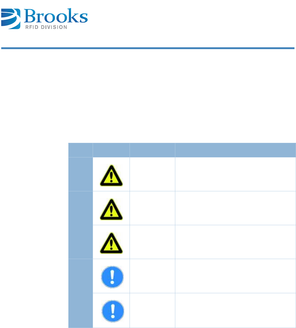
Sym bols a n d signa l w or ds
The following sym bols and signal words are used in t his docum ent at ion. The
com binat ion of a pict ograph and a signal word classifies t he respective safet y
inform ation. The sym bol can vary depending on the ty pe of danger.
Sym bol Signa l w ord D escr ip t ion
D ea t h
D AN GER This signal w ord m ust be used if deat h or
irreversible dam age to healt h can occur if
the hazard inform at ion is not followed.
Risk of inj ur y a nd
pr oper t y dam age
W ARN I N G This signal word indicat es bodily inj uries
and pr opert y dam age including inj uries,
accident s, and healt h risks.
CAUTI ON This signal word indicat es a risk of
propert y dam age. I n addit ion, t here is a
slight risk of inj uries.
N o da m a ge
ATTEN TI ON This signal w ord warns of m alfunctions
and m ay only be used if no dam age t o
health can occur.
I M PORTAN T This signal w ord indicat es cross-
references and ways in which operat ions
are facilit at ed. I t excludes all risks of
propert y dam age and inj ury risks.
I nform a t ion
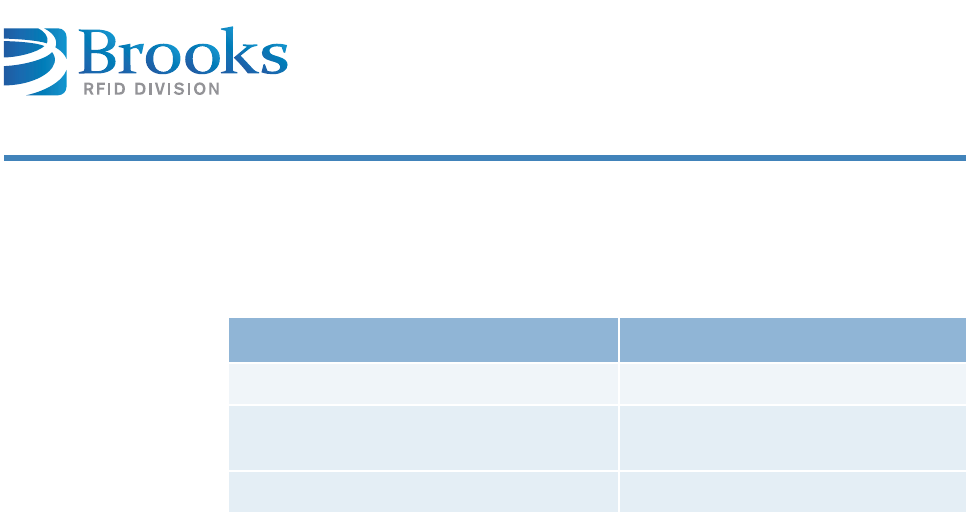
Ta rge t gr oup
This product m anual is addressed t o personnel wit h t he following areas of
responsibility:
Definition according t o DI N EN 60204- 1:
I nst r uct e d pe rson ne l
Persons who have been inst ruct ed and, if required, t rained by a specialist as t o
the t asks assigned to t hem , t he possible risks of incorrect behavior and t he
required safet y equipm ent and safet y m easures.
Spe cialize d per sonn el
Persons who can evaluat e t he work assigned t o t hem and recognize possible r isks
based on t heir specialized t raining, knowledge, experience and fam iliarity wit h
the r elevant st andards.
Ar ea of r espon sibilit y Com p e t en ce
I nst allat ion Specialized personnel
Com m issioning, operat ion and
decom m issioning
I nstr uct ed personnel
Troubleshoot ing Specialized personnel

Con t ent s
1 I de nt ification . . . . . . . . . . . . . . . . . . . . . . . . . 7
1 .1 De signat ed u se 8
1 .2 I ncor re ct u se 8
2 Decla ra t ion of Confor m it y . . . . . . . . . . . . . . . 1 0
3 Gene ral I nst ru ct ions . . . . . . . . . . . . . . . . . . . 12
3 .1 Liabilit y a n d w a r ran t y 1 2
3 .2 Obj e ct ive s of t he pr oduct m anua l 1 2
4 Sa fet y I n st ruct ion s . . . . . . . . . . . . . . . . . . . . 14
4 .1 Are a of a pplica t ion a nd sym bols 1 4
4.1.1 Safet y sym bols – in com pliance wit h 4844- 2 15
4.1.2 Warning sy m bols 15
4.1.3 Prohibit ion sym bols 15
4.1.4 Ot her sym bols 16
4 .2 Obliga t ions 1 7
4.2.1 Operat ing com pany’s obligat ions 17
4.2.2 Operat ing personnel’s obligations 17
4 .3 ESD inst ruct ions 1 8
4 .4 Residua l r isk s 1 8
4 .5 Addit iona l in for m a t ion 2 0
5 Pr oduct Specifica t ions . . . . . . . . . . . . . . . . . . 2 2
5 .1 Fu nct ion 2 2
5 .2 I m a ges 2 3
5.2.1 Front view 23
5.2.2 Rear view 24
5.2.3 Top view 25
5 .3 De scr ipt ion of t he com pon en t s 2 6
5 .4 Te chnical dat a 2 8
6 I n st alla tion . . . . . . . . . . . . . . . . . . . . . . . . . . 30
6 .1 Sa fe t y in st r uct ions 3 0
6 .2 Qu a lified inst a lla t ion pe rsonn el 3 2
6 .3 Un pa ck ing 3 2
6 .4 Assem bly of t he device 3 3
6 .5 Ant enna inst a lla t ion 3 4

Con t ent s
6.5.1 Posit ioning t he antenna 34
6.5.2 Available ant enna t ypes 34
6 .6 Pow e r supply 3 4
6 .7 Term in al conn ect ion 3 5
6 .8 Ex t e rna l input a nd out put ( opt ion al) 3 6
6 .9 Com m ission ing 3 6
6.9.1 Required operat ing conditions 36
6.9.2 Param et ers of t he serial int erface 36
6.9.3 Param et ers of t he Ethernet int erface 37
7 Ope rat ion . . . . . . . . . . . . . . . . . . . . . . . . . . . 4 0
7 .1 Ope r a t ing pe r sonne l 4 0
7 .2 Com m unica t ion pr ot ocol ASC- I 1 4 0
7.2.1 St ructure of t he com m unicat ion prot ocol 40
7.2.2 Package cont ent s 41
7.2.3 Com m ands of protocol 43
7.2.4 Param eters 126
7 .3 Addit iona l in for m a t ion 1 5 5
8 Se rvice an d Tr oubleshoot ing . . . . . . . . . . . . 1 5 6
8 .1 Gene ra l r e m a r k s 1 5 6
8 .2 Qu a lifie d t r oublesh oot in g per son ne l 1 5 7
8 .3 Sa fe t y in st r uct ions 1 5 7
8 .4 Er r or codes 1 5 8
8 .5 Er r or displa y w it h LED 1 6 0
8 .6 Rea de r doe s not r espond 1 6 0
8 .7 Re set 1 6 1
8 .8 Pow er cut 1 6 1
8 .9 Soft w a re r ele a se s 1 6 1
8 .1 0 Cust om e r ser vice 1 6 1
9 Dism a nt ling and St ora ge . . . . . . . . . . . . . . . 16 2
9 .1 Dism a nt ling 1 6 2
9 .2 St o ra ge 1 6 2
1 0 Tr anspor t a nd Disposa l . . . . . . . . . . . . . . . . 1 6 3
1 0 .1 Tr an spor t 1 6 3
1 0 .2 Disposal 1 6 3

Product M an ua l - RFI D Rea de r UF7 0 Cert um 7
Cha pt er 1
I den t ifica t ion
1 I de nt ifica t ion
This chapt er gives you an overview of the following t opics:
■ Designat ed use
■ I ncorrect use
Model RFID Reader UF70 Cert um
Serial num ber 00 – 0001 – UF70
Part num ber TUG- E1ML- 4O00- F4- 00E1 ETSI version, prot ect ion class I P40
TFG- E1ML- 4O00- F4- 00E1 FCC version, prot ection class I P40
TUG- E1ML-4O00- R4- 00E1 ETSI version, prot ection class I P65
TFG- E1ML- 4O00- R4- 00E1 FCC version, prot ect ion class I P65
M a nu fa ct u r er
Brooks Aut om at ion ( Germ any) Gm bH
RFID Division
Gart enst r. 19
D- 95490 Mist elgau
GERMANY
Telephone + 49 ( 0) 9279 - 991 550
Fax + 49 ( 0) 9279 - 991 501
E- m ail info.rfid@brooks.com
Websit e www.brooks- rfid.com
For inform at ion on t he label, see Device label.

Product M an ua l - RFI D Rea de r UF7 0 Cert um 8
Cha pt er 1
I den t ifica t ion
1 .1 De signa t ed use
This product is exclusively developed for reading and writ ing of passive UHF
transponders ( e.g. EPC Class1 Gen2) . Any ot her use of t his device const it utes
m isuse and renders t he user's aut horit y to inst all and operat e t he device invalid.
This product is designed t o be m ount ed and operat ed in an indust rial set t ing as a
built- in- device only. I t is not designed t o be used as a stand- alone or port able
device or in a non- indust r ial sett ing, such as a household, vehicle or in t he open-
air.
I nt ended use also includes t he following:
■following all instruct ions in t he product m anual
■following all safet y inform at ion
Before using the device, t he user should ensure t hat t he national approval
requirem ent s for use are m et .
User in for m a t ion
FCC
Changes or m odificat ions not expressly approved by t he part y responsible for
com pliance could void t he user’s aut horit y t o operat e t he equipm ent .
1 .2 I ncor re ct use
I ncorrect use, which can endanger t he device, t he user and third part ies,
includes:
■the use of t he device, cont rary t o it s intended use ( Designat ed use)
■m odifying, ext ending or reconst ructing t he device wit hout first consult ing
Brooks Aut om at ion ( Germ any) Gm bH
■operat ing t he device when t here are obvious problem s
I M PORTAN T This equipm ent has been t est ed, and found t o com ply w ith the lim it s for a Class
A digit al device, pursuant t o part 15 of t he FCC Rules. These lim it s are
designed t o provide reasonable prot ect ion against harm ful int erference when
the equipm ent is operat ed in a com m ercial environm ent . This equipm ent
generates, uses, and can radiat e radio frequency energy and, if not inst alled
and used in accordance with t he instruction m anual, m ay cause harm ful
int erference t o radio com m unicat ions. Operation of t his equipm ent in a
resident ial area is likely t o cause harm ful int erference, in which case t he user
will be required t o correct t he int erference at his own expense.
nbb

Product M an ua l - RFI D Rea de r UF7 0 Cert um 9
Cha pt er 1
I den t ifica t ion
W ARN I N G Risk of inj u ry t hr ough incorre ct m odificat ions
Ther e are risks from unaut horized m odificat ions t o t he m achine.
Only use original spare par ts from t he m anufacturer. Do not m ake any changes,
at t achm ent s or m odificat ions t o t he device wit hout t he approval of Brooks
Aut om at ion ( Germ any) Gm bH.
W ARN I N G Risk of inj u ry and m alfun ction of m a chine ope ra t ion t h rough
incorre ct u se
Ther e are risks at t ached t o using t he device incorr ectly.
Use t he device exclusively according t o it s int ended use.

Product M an ua l - RFI D Rea de r UF7 0 Cert um 1 0
Cha pt er 2
Declaration of Conform it y
2 Declar a t ion of Confor m it y
Konform it ät se rklär un g gem äß de m Geset z ü be r Funk a n lagen un d
Telek om m un ik at ionse nde in richt un gen ( FTEG) und de r Rich t linie
1 9 9 9 / 5 / EG ( R& TTE)
Declarat ion of Confor m it y in accordance with the Radio and Telecom m unicat ions
Term inal Equipm ent Act ( FTEG) and Direct ive 1999/ 5/ FC ( R&TTE Direct ive)
Herst eller / Verantwortliche Person
Manufacturer / responsible person
BROOKS Aut om a t ion
( Ger m a ny) Gm bH /
He r r Dit t rich
erklärt , dass das Produkt
declares t hat t he product
UF7 0 Ce r t um
Type ( ggf. Anlagenkonfigurat ion m it Angabe der
Module)
Type ( if applicable, configurat ion including t he
m odules)
Telek om m unik at ions( Tk- ) endeinr icht ung
Telecom m unicat ions t erm inal equipm ent
Funkanlage
Radio equipm ent
Verwendungszweck
I ntended purpose
I de nt ificat ion syst em
Gerät eklasse
Equipm ent class
2
bei best im m ungsgem äßer Verwendung den grundlegenden Anforderungen des
§ 3 und den übrigen einschlägigen Bestim m ungen des FTEG ( Artikel 3 der
R&TTE) ent spricht .
com plies wit h t he essent ial requirem ent s of § 3 and t he ot her relevant provisions
of t he FTEG ( Art icle 3 of t he R&TTE Direct ive) , when used for it s int ended
purpose.
Gesu ndh eit un d Sich er he it ge m ä ß § 3 ( 1 ) 1 . ( Art ik el 3 ( 1 ) a ) )
Healt h and safet y requirem ent s pursuant t o § 3 ( 1) 1. ( Art icle 3( 1) a) )
angewendet e harm onisiert e Norm en
Harm onized st andards applied
EN 6 0 9 5 0 - 1 :2 0 0 6
Einhalt ung der grundlegenden Anforderungen auf
andere Art und Weise ( hierzu verwendete Standards/
Spezifikat ionen)
Ot her m eans of proving conform it y wit h t he essent ial
requirem ent s ( standards / specificat ions used)
- - -

Product M an ua l - RFI D Rea de r UF7 0 Cert um 1 1
Cha pt er 2
Declaration of Conform it y
Schu t za nfor der un gen in Bez ug a uf die elek t r om a gne t isch e
Ver t r ä glichk e it ( § 3 ( 1 ) 2 , Ar t ik e l 3 ( 1 ) b)
Protect ion requirem ent s concerning elect rom agnet ic com pat ibilit y § 3( 1) ( 2) ,
( Art icle 3( 1) ( b) )
angewendet e harm onisiert e Norm en
Harm onized st andards applied
EN 3 0 1 4 8 9 - 1 V1 .8 .1
EN 3 0 1 4 8 9 - 3 V1 .4 .1
Einhalt ung der grundlegenden Anforderungen auf
andere Art und Weise ( hierzu verwendete Standards/
Spezifikat ionen)
Ot her m eans of proving conform it y wit h t he essent ial
requirem ent s ( standards / int erface specificat ions
used)
Ma ß na hm en zur effiz ien t e n N ut zu ng de s Fu nk fr eque nzspek t r um s
Measures for t he efficient use of t he radio frequency spect rum
Luft schnit t stelle bei Funkanlagen gem äß § 3( 2) ( Art ikel 3( 2) )
Air int erface of t he radio syst em s pursuant t o § 3( 2) ( Art icle 3( 2) )
angewendet e harm onisiert e Norm en
Harm onized st andards applied
EN 3 0 2 2 0 8 - 1 V1 .3 .1
EN 3 0 2 2 0 8 - 2 V1 .3 .1
Einhalt ung der grundlegenden Anforderungen auf
andere Ar t und Weise ( hierzu verw endete St andar ds/
Spezifikat ionen)
Ot her m eans of proving conform it y wit h t he essent ial
requirem ent s ( standards/ specificat ions used)
- - -
BROOKS Autom at ion ( Germ any) Gm bH
Gart enst r. 19
D- 95490 Mist elgau
GERMANY
Te l e p h o n e
Fax
E- Mail
+ 49 ( 0) 9279 - 991 550
+ 49 ( 0) 9279 - 991 501
info.r fid@brooks.com
Mist elgau, July 21, 2011 Gerald Dit t rich
( Place and dat e of issue) ( Nam e and signat ure)
nbb

Product M an ua l - RFI D Rea de r UF7 0 Cert um 1 2
Cha pt er 3
Ge neral I nst ruct ions
3 Ge ne r al I nst ruct ions
This chapt er gives you an overview of the following t opics:
■ Liabilit y and warrant y
■ Obj ect ives of the product m anual
3 .1 Lia bilit y and w arranty
The “ General sales and delivery condit ions” of Brooks Aut om ation ( Germ any)
Gm bH always apply.
The warranty period is 12 m ont hs beginning wit h t he delivery of t he device, which
is verified by t he invoice or ot her docum ent s.
The warranty includes repair s of all dam age t o t he device t hat occurs during t he
warrant y period and was clearly caused by m at erial or m anufact uring defect s.
Liabilit y and warranty claim s in cases of inj ury t o persons or dam age to propert y
are excluded if t hey can be at t ributed t o one or m ore of t he follow ing causes:
■incorrect use of t he device
■disregard of t he inform ation in t he product m anual
■unauthorized st ruct ural m odificat ions of t he device
■insufficient m aint enance and repairs
■disast ers due t o foreign obj ect s or force m aj eure
3 .2 Obj ect ives of t he product m anua l
This product m anual serves as support and contains all t he necessary safety
inform ation t hat m ust be followed for general safet y, t ransport , inst allat ion and
operat ion.
This product m anual wit h all safety infor m at ion ( as w ell as all addit ional
docum ents) m ust be:
■followed, read and under st ood by all persons working wit h t he device
( especially t he safety inform at ion)
■easily available t o all persons at all t im es
■im m ediat ely consulted in case of t he least doubt ( safety)

Product M an ua l - RFI D Rea de r UF7 0 Cert um 1 3
Cha pt er 3
Ge neral I nst ruct ions
Obj ect iv es:
■avoid accident s
■incr ease t he service life and reliabilit y of t he device
■reduce costs due t o product ion dow nt im es
nbb
Product M an ua l - RFI D Rea de r UF7 0 Cert um 1 4
Cha pt er 4
Sa fety I nst ruct ions
4 Safet y I nst ruct ions
This chapt er gives you an overview of the following t opics:
■ Area of applicat ion and sym bols
■ Obligat ions
■ ESD inst ruct ions
■ Residual risks
■ Addit ional inform at ion
4 .1 Area of application a nd sym bols
The device was const ructed according t o stat e- of- the- art technology and
recognized safet y r egulat ions. I n order t o prevent any risks t o life and lim b of t he
user, t hird part ies or dam age t o t he device, only use the device for it s int ended
purpose and in perfect condit ion wit h regard to safet y.
Bodily inj uries and/ or propert y dam age result ing from non- com pliance wit h t he
instr uct ions given in t he product m anual are t he responsibilit y of t he com pany
operat ing t he device or of t he assigned personnel. Malfunct ions t hat could
com prom ise safet y m ust be elim inat ed im m ediat ely.
D AN GER Da nge r t o life, r isk of inj ur ies or da m a ge t o pr oper t y
Risks exist when disregarding t he product m anual and t he safet y inst ruct ions
therein.
Carefully read t he product m anual before init ial com m issioning. Perform t he
required safety m easures before init ial com m issioning.
Follow t he general safet y inform ation as well as t he special safet y inform ation
given in other chapters.
Product M an ua l - RFI D Rea de r UF7 0 Cert um 1 5
Cha pt er 4
Sa fety I nst ruct ions
4 .1 .1 Safe t y sym bols – in com plia nce w it h 4 8 4 4 - 2
Special safety sym bols in accordance wit h DI N 4844- 2 are used in t he
corresponding passages in t he t ext of t his product m anual and require special
at t ention depending on t he com binat ion of signal w ord and sym bol.
4 .1 .2 W ar ning sym bols
4 .1 .3 Prohibit ion sym bols
W ARN I N G Risk of inj ur ie s w he n disre ga rding sa fe t y sym bols
Risks exist when disregarding warnings in t he product m anual.
Please heed t he warnings.
W a r ning a ga in st
ha za rdous are a
W a r ning a ga in st
ha za rdous e le ct r ical
volt a g e
W a r ning a ga in st
ele ct r om agne t ic
r a dia t io n
W a r ning a ga in st
flam m able m a t e r ials
W a r ning a ga in st
pot e nt ially ex plosive
a t m osp he r e
W a r ning a ga in st
ele ct r ost at ica lly
sen sit ive com pon en t s
Una ut h or ize d a ccess
is prohibit ed
Fire , ope n flam e an d
sm ok ing is pr oh ibit ed
Sw it chin g is
pr oh ib it e d
Pr oh ib it ion
nbb
Product M an ua l - RFI D Rea de r UF7 0 Cert um 1 6
Cha pt er 4
Sa fety I nst ruct ions
4 .1 .4 Ot her sym bols
Dispose of pa ck in g
m at er ia l a ccor ding t o
r egu la t ion s
Re cycling
I m por t a nt
in for m a t io n
Re fe r t o m a nu a l
Disconn ect from
pow e r supply

Product M an ua l - RFI D Rea de r UF7 0 Cert um 1 7
Cha pt er 4
Sa fety I nst ruct ions
4 .2 Obliga t ions
4 .2 .1 Ope r a t ing com pa ny’s obliga tions
The safe condition and use of the device is a requirem ent for t he safe operat ion of
the device. The com pany operat ing t he device t herefore has t he obligat ion t o
ensure t hat t he following point s are adhered t o:
4 .2 .2 Ope r a ting per sonnel’s obligat ions
Operat ors are obligat ed t o contr ibut e t o t he prevent ion of w ork accident s and the
consequences of t hem by t heir personal conduct .
The device m ay only be operat ed by t rained and aut horized per sonnel!
Avoid unsafe and/ or dangerous work procedures! I f necessary, check
em ployees' act ions!
Only perm it personnel t o be trained or inst ruct ed wit hin t he scope of a
general t raining work on the device under t he supervision of an
experienced person!
Personnel m ust have underst ood the product m anual. Have t his confirm ed
by signature!
Precisely establish responsibilit ies according to t he various t ask areas
( operat ion, inst allat ion) !
Operat ing personnel m ust be com m it t ed t o im m ediat ely report ing t o their
superior any ident ifiable safet y deficiencies which occur!
Product M an ua l - RFI D Rea de r UF7 0 Cert um 1 8
Cha pt er 4
Sa fety I nst ruct ions
4 .3 ESD inst ruct ions
4 .4 Re sidua l risk s
Even if all precaut ions have been t aken, t here m ay be unapparent residual risks!
Adhering t o t he safety instr uct ions, the int ended use, and t he product m anual as
a whole can reduce residual risks!
W ARN I N G Risk of inj ur ie s due t o insufficien t per sonnel qu alificat ions
A risk exist s for personnel and t he proper operat ion due t o insufficient ly
qualified per sonnel.
Only t rained personnel m ay operat e t he device. New operat ors m ust be
inst ruct ed by the current operat ing per sonnel. The operating com pany m ust
precisely regulat e and m onit or t he personnel's areas of responsibilit y and
com pet ence.
Personnel for t he areas of responsibilit y m ent ioned above m ust have t he
corresponding qualificat ion for t his work ( training, instruct ions) . I f necessary,
this can be done by t he m anufact urer on behalf of t he operat ing com pany.
All warrant y claim s are void when disregarded.
CAUTI ON St at ic elect ricity can dam age electronic com ponent s in t he device. All persons
inst alling or m aint aining the device m ust be t rained in ESD prot ect ion.
ESD protect ive m easures m ust be applied when opening t he device.
Disconnect t he power supply prior t o rem oving or adding com ponent s.
Discharge your body and all t ools used prior t o cont act ing any com ponent s
on t he int erior of t he device!
Touch elect ronically sensitive part s carefully and at t he corners!
Product M an ua l - RFI D Rea de r UF7 0 Cert um 1 9
Cha pt er 4
Sa fety I nst ruct ions
D AN GER Risks fr om ele ct r ic cur r en t
Elect rical energy rem ains in lines, equipm ent and devices even when t he device
is switched off.
Only allow qualified elect ricians t o perform work on the electrical supply
sy stem .
ATTEN TI ON Disconnect t he device from the power supply system if active part s of t he
device can be accessed by using t ools. Access is only perm itted for aut horized
personnel.
Regularly check t he elect rical equipm ent of t he device. Regularly check all
m oving cables for dam age wit hin t he scope of m aint enance and repair s.
D AN GER Risk of fir e and e xplosions
Fire and explosions m ay occur wit hin t he vicinit y of t he device.
Sm oking, open flam es and fire are st rict ly prohibit ed in t he vicinity of the
device. Do not store any flam m able liquids wit hin t he hazar dous area. Keep a
fire ext inguisher in the vicinity of t he device.
W ARN I N G W a r ning aga in st e lect r om a gne t ic radia t ion
Elect rom agnet ic radiat ion develops when t ransm it t ing and receiving dat a.
Set the ant enna in such a posit ion t hat it is not in t he vicinity of or touches a
hum an body while t ransm it t ing.

Product M an ua l - RFI D Rea de r UF7 0 Cert um 2 0
Cha pt er 4
Sa fety I nst ruct ions
4 .5 Addit ional inform a t ion
■Read and understand all safety and pr oduct m anuals prior t o inst alling
and operat ing t he device.
■This docum ent at ion was writ t en for specifically t rained personnel.
I nstallation, operat ion and t roubleshooting m ay only be carried out by
specifically t rained personnel.
■Retain t hese inst ruct ions. Keep t his docum ent at ion in a locat ion t hat is
accessible t o all per sonnel involved wit h t he inst allat ion, use and
tr oubleshoot ing of t he device.
■Follow all warnings. Follow all warnings on and in t he device and in t he
docum ent at ion.
■I nstall t he device only in accor dance wit h t he m anufact urer's
inst ruct ions.
■Use only the accessories and cables from t he m anufact urer.
■Troubleshoot ing t hat is not described in Chapt er Service and
Troubleshoot ing m ay only be perform ed by the m anufacturer.
■People wit h hearing aids should be aware t hat the radio signals em it t ed
by the device can cause annoying noises in t he hearing aid.
■Do not connect t he device t o power supplies such as norm al household
electrical out let s. The device should only be connect ed t o power supplies
as specified in t his docum ent .
■When rem oving a cable, only pull on t he plug and not on t he cable.
Connect cable connectors straight and carefully t o avoid dam aging t he
cont acts.
■Never overbend t he ant enna cables or subj ect t hese t o m echanical
forces.
■When replacem ent part s are required, use only t he replacem ent part s
that were specified by the m anufacturer. Unaut horized spare part s can
result in fire, elect r ic shock or ot her hazards.

Product M an ua l - RFI D Rea de r UF7 0 Cert um 2 1
Cha pt er 4
Sa fety I nst ruct ions
Rules a nd
r egu la t ion s
The provisions of t he accident prevent ion regulat ions of t he governm ent safet y
organizat ions always apply t o all wor k on the device.
The following m ust also be observed:
■applicable legally binding accident - prevent ion regulat ions
■applicable binding regulat ions at t he place of use
■the recognized technical rules for safe and professional work
■exist ing environm ent al prot ect ion regulat ions
■ot her applicable regulat ions

Product M an ua l - RFI D Rea de r UF7 0 Cert um 2 2
Cha pt er 5
Pr oduct Specificat ions
5 Product Spe cifica tions
This chapt er gives you an overview of the following t opics:
■ Function
■ I m ages
■ Descript ion of the com ponent s
■ Technical dat a
5 .1 Fu nct ion
The Brooks RFI D UF70 Cert um r eader is a m ultiprot ocol reader for reading
passive t ransponders in t he frequency range of 865 MHz t o 868 MHz for Europe
and 902 MHz - 928 MHz for t he FCC.
The device operates at 2 W and 1 W HF power at the ant enna j ack depending on
the r egistrat ion area.
When delivered, t he device can read and write t ransponders according t o t he EPC
Gen2 st andard. Other prot ocols can be added via soft ware updat es.
The device has several high perform ance int erfaces for com m unicat ions.
The reader has four ant enna port s for the connect ion of t ransm it t ing and
receiving ant ennas for com m unicat ing wit h RFI D t ransponders.
The device also has various int erfaces for t he connect ion wit h t he PC, depending
on t he configuration stage. Power is supplied via a 3- pin M8 connect or.
Product M an ua l - RFI D Rea de r UF7 0 Cert um 2 3
Cha pt er 5
Pr oduct Specificat ions
5 .2 I m a ges
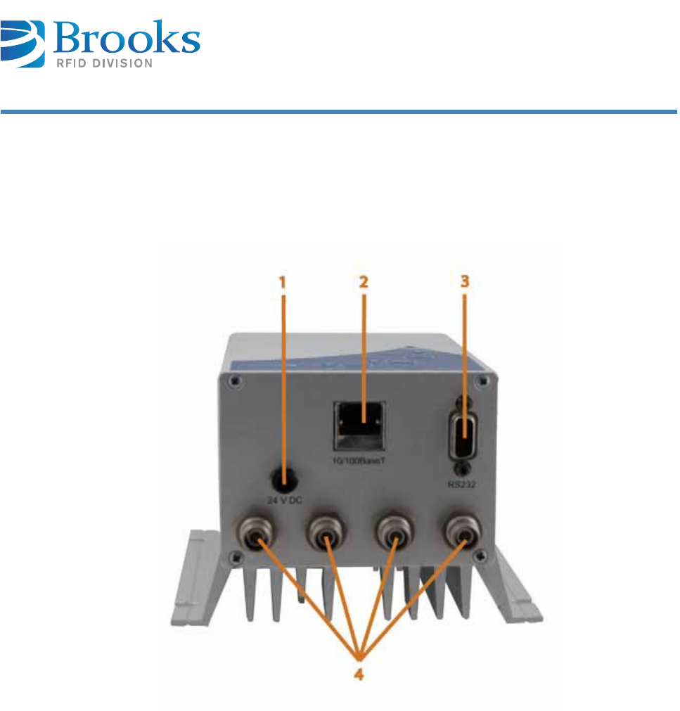
5 .2 .1 Fr on t view
1Pow er ( 2 4 V) 3RS232 int erface
2Ethernet int erface 44 antenna port s
nbb
Product M an ua l - RFI D Rea de r UF7 0 Cert um 2 4
Cha pt er 5
Pr oduct Specificat ions
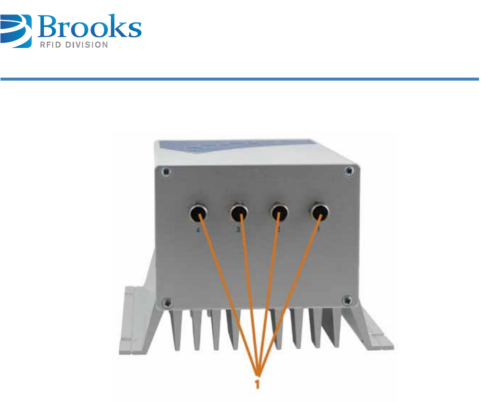
5 .2 .2 Re a r vie w
14 I / Os
Product M an ua l - RFI D Rea de r UF7 0 Cert um 2 5
Cha pt er 5
Pr oduct Specificat ions
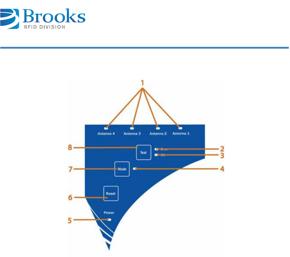
5 .2 .3 Top view
1Ant enna port LED 5Mode LED
2Test Error LED 6Mode but t on
3Te s t O K LED 7Reset but t on
4Test but t on 8Pow er LED

Product M an ua l - RFI D Rea de r UF7 0 Cert um 2 6
Cha pt er 5
Pr oduct Specificat ions
5 .3 Descript ion of t he com pone nt s
Com p on en t s D escr ip t ion
Pow er LED I f t he correct volt age is applied t o t he device, t he
Pow er LED is gr een and t he device is operat ional.
Reset but t on Pressing t his but t on init iat es a power- reset of t he
device. The reset but t on m ust be pressed for at least
t hree seconds unt il all t he LEDs of t he foil keypad
sim ult aneously start and t he hardware reset is
execut ed.
Mode but t on I f t he m ode but t on and t he reset but t on are
sim ult aneously pressed at a powerup reset for about
15 seconds unt il all t he LEDs of t he keypad light up for
t he second t im e, t he reader will be reset to the default
st at e ( default factory setting) .
Mode LED Current ly no use.
Test but t on Pressing t his but t on swit ches t he device to t he reading
t est m ode and is used t o select t he ant enna port s. I f
t he but t on is pressed for a longer t im e ( at least 2
seconds), t hen the test m ode is act ivated ( Test OK LED
and Test Error LED bot h briefly com e on) or disabled
( Test OK LED and Test Error LED both go out ) . Briefly
pressing t he but t ons when t he test m ode is activat ed
result s in swit ching t o t he next antenna port .
Te s t O K LED When a t ransponder in t he t est m ode can be
successfully ident ified, t his LED t urns green.
Test Error LED When a t ransponder in t he t est m ode cannot be
successfully ident ified, t his LED t urns red.
Ant enna port LED 1
to 4
These LEDs signal t he dat a t raffic t o t he respective
antenna port s. Once data is read or writ t en via t he
antenna por t 1 ( above) , t he ant enna port LED 1
( above) t urns green.
Ant enna port s Ports t o connect t he ant ennas.
I / O port s 1 t o 4 A digital input and out put can be connect ed t o each
antenna port . A 3 wire sensor or dry contact is possible
as t he input . The output can operat e a LED wit hout a
series resist or or direct ly sw it ch 5 V DC
( I m ax = 100 m A) .

Product M an ua l - RFI D Rea de r UF7 0 Cert um 2 7
Cha pt er 5
Pr oduct Specificat ions
RS232 int erface Com m unicat ions wit h t he device can be m ade via t he
serial int erface ( 9 pin sub- D socket ) . Baudrat es of
1,200 Bd up t o 57,600 Bd are possible.
Ethernet int erface Com m unicat ions wit h t he device can be m ade via t he
10/ 100 BaseT int erface.
Volt age supply
connect ion
Cont act for connect ing t he 24 V DC volt age supply
Com p on en t s D escr ip t ion

Product M an ua l - RFI D Rea de r UF7 0 Cert um 2 8
Cha pt er 5
Pr oduct Specificat ions
5 .4 Technica l data
Technica l da t a
Volt ag e 24 V DC ± 10%
Power consum pt ion approx. 0.8 A at 24 V
Operat ing t em perat ure - 20 to 50 ° C
- 4 ° F t o 122 ° F
St orage t em perat ure - 40 t o 85 ° C
- 40 ° F t o 185 ° F
Perm issible hum idity at
50 ° C / 122 ° F
25 – 85%
Prot ect ion class I P 40 ( opt ional I P 65)
Housing m at erial Passivat ed alum inum
Wei gh t approx. 1,500 g
Air interface I SO 18000- 6C ( EPC Global Class 1 Gen2)
Frequency range Europe 865 – 868 MHz
Frequency range FCC 902 – 928 MHz
Radiat ion power < 2 Wat t ERP
Transm it t ing power program m able in 1 dB steps
Read / w rit e range up t o 8 m
Serial int erface RS232 1,200 Bd – 57,600 Bd
Ethernet int erface 10/ 100 BaseT
Product M an ua l - RFI D Rea de r UF7 0 Cert um 2 9
Cha pt er 5
Pr oduct Specificat ions
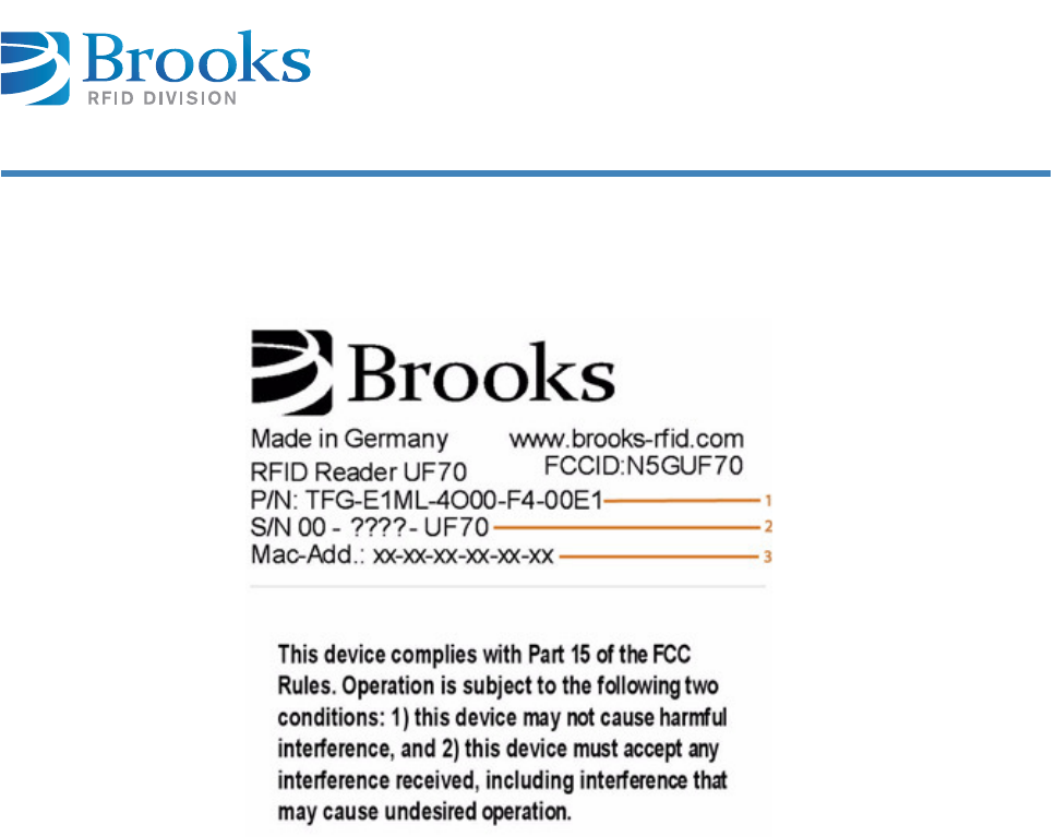
De vice la bel The device label with the CE m ark, part / serial num ber and MAC address is on t he
device housing.
1Par t num ber
2Serial num ber
3MAC address
Product M an ua l - RFI D Rea de r UF7 0 Cert um 3 0
Cha pt er 6
I nst a lla t ion
6 I nst a lla t ion
This chapt er gives you an overview of the following t opics:
■ Safety instr uct ions
■ Qualified installat ion personnel
■ Unpacking
■ Assem bly of t he device
■ Ant enna inst allat ion
■ Pow er supply
■ Term inal connect ion
■ Ext ernal input and out put ( opt ional)
■ Com m issioning
6 .1 Sa fety in st r uct ions
Re fe r t o m a nu a l
Follow t he general safet y instructions in t he chapt er Safet y I nst ruct ions.
CAUTI ON The device is exclusively designed for indoor use in an industrial environm ent .
I nstallation is only allowed in an int erior room at a constant t em perat ure
bet ween - 20 ° C / - 4 ° F and + 50 ° C / 122 ° F, and a relat ive hum idity betw een
25% and 80% .
Never use t he device near or in wat er.
Never pour liquids of any t ype over t he device. I f t he device should accident ally
com e in cont act wit h liquid, disconnect it and have it checked by a t echnician.
Do not inst all t he device near heat sources such as radiat ors, heat regist ers,
st oves or other devices ( including am plifiers) that generat e heat .
Do not inst all the device in a flam m able environm ent .
Product M an ua l - RFI D Rea de r UF7 0 Cert um 3 1
Cha pt er 6
I nst a lla t ion
CAUTI ON Never expose t he device to ext rem e t em perat ure fluct uations, since ot herwise
condensat ion develops in the device and causes dam age.
Do not install the device in t he vicinit y of volt age lines or ot her power lines wit h
which they could collide ( for exam ple, drilling) , which could result in serious
inj ur ies or even deat h.
The device ( especially t he ant enna) should not be installed in the im m ediat e
vicinity of elect rical equipm ent such as m edical devices, m onit ors, t elephones,
TV set s, m agnet ic disks and m etal obj ect s.
This could result in reduced read and writ e ranges.
Never use t he device in explosive areas ( e.g. paint warehouses).
CAUTI ON Do not use t he device in areas where it is exposed t o vibrations or shocks.
ATTEN TI ON The inst allat ion locat ion m ust be adequat ely illum inat ed during the installat ion.
Never install t he device during a light ning st orm .
Verify that t he installat ion m eet s t he requirem ent s of t he ( count ry- specific)
FCC for hum an exposure to radio frequencies.
nbb
Product M an ua l - RFI D Rea de r UF7 0 Cert um 3 2
Cha pt er 6
I nst a lla t ion
6 .2 Qualified inst a llation pe rsonnel
6 .3 Unpa ck ing
The device and t he accessories are packed under clean- room conditions. I n order
to m aint ain t his condit ion, t he device m ust also be unpacked in clean- room
condit ions.
Disposing of t he
pa ck a ging m a t e rial
ATTEN TI ON When det erm ining t he installation sit e, keep in m ind t he lengt h of the ant enna
wire and t he read/ writ e range of the antenna used.
CAUTI ON The inst allat ion is t o be carried out by specially t rained per sonnel only. I f you
are uncert ain about t heir qualificat ion, cont act t he m anufact urer.
CAUTI ON I nstalling t he device without special training can result in dam age t o t he reader
and/ or connected devices.
The packaging m aterial consists of cardboard and foil. Dispose of t hese
m at erials separat ely and under t he respect ive legal regulations of your count ry.
Product M an ua l - RFI D Rea de r UF7 0 Cert um 3 3
Cha pt er 6
I nst a lla t ion
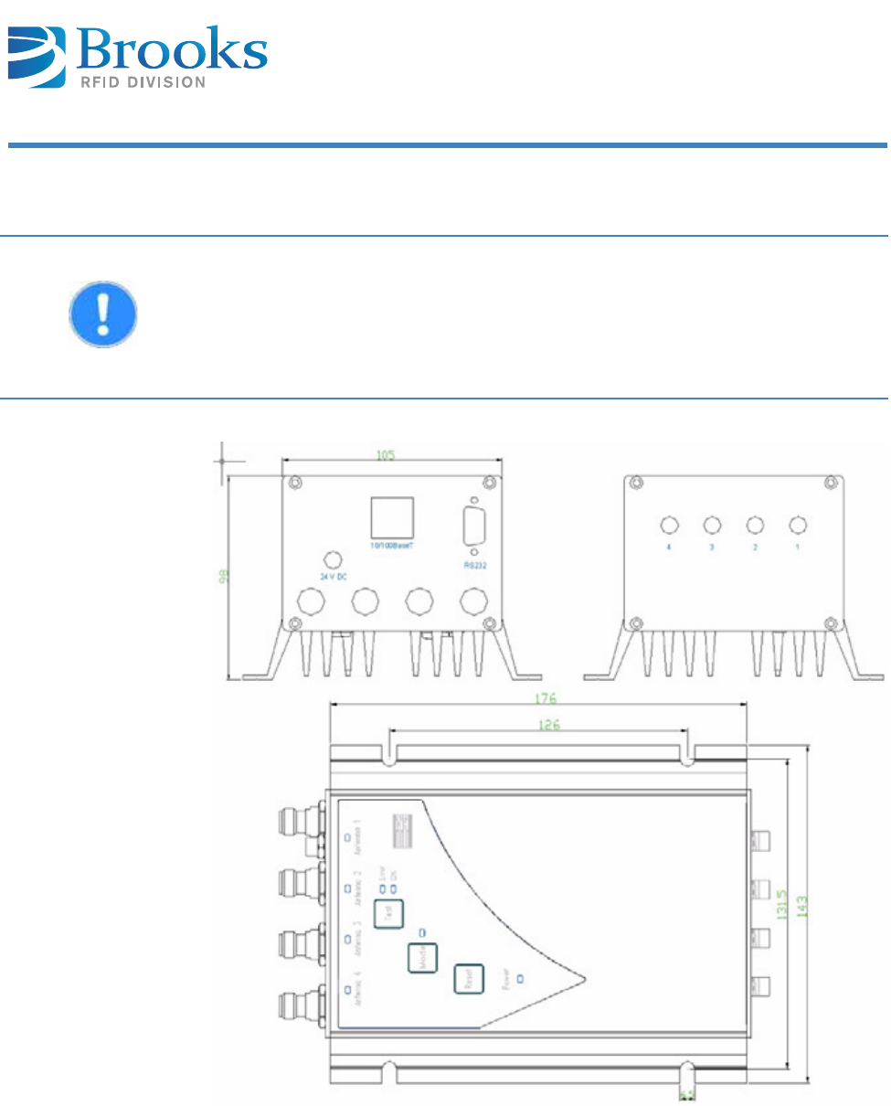
6 .4 Assem bly of t he de vice
I nst a lla t ion
dim en sion s
ATTEN TI ON The m ount ing surface m ust be st able, non- flam m able, dry and clean.
I f necessary, clean it befor e you install t he device.
The device m ust be inst alled so t hat air can freely circulat e vert ically t hrough
the heat sink, and the operating and environm ent al conditions specified under
Technical dat a are m et at all t im es.
Product M an ua l - RFI D Rea de r UF7 0 Cert um 3 4
Cha pt er 6
I nst a lla t ion
6 .5 Antenna inst a lla t ion
6 .5 .1 Posit ioning t h e a nt e n na
Reliable reading and writ ing depends on the dist ance and orient at ion of t he
transponder from the ant enna.
Depending on t he polarization of t he ant enna and t he design of t he t ransponder,
the orient at ion of t he t wo t oget her should be considered when a reliable
ident ificat ion m ust be guarant eed.
Mor e inform at ion on applicat ion- specific ant enna st ruct ures can be obt ained from
our support team .
6 .5 .2 Available a nt enna t ype s
Different t ypes of ant ennas are available on request .
6 .6 Pow er supply
The device can be connect ed t o an internal power supply of the syst em or to an
ext ernal pow er supply.
Once the device is connected to the power supply, t he pow er LED light s up.
ATTEN TI ON Consider the required read and writ e ranges when inst alling t he ant enna. The
reader can only be used properly if t he t ransponder is locat ed within the
individual reading/ writ ing range of t he respect ive ant enna.
I f t he t ransponder is very close t o t he ant enna, t he t ransponder m ay be
det uned by t he m etal of t he antenna and a reading/ w rit ing is not possible. We
recom m end keeping a m inim um dist ance bet ween t ransponder and antenna of
about 10 m m .
D AN GER Risk of de a t h fr om da ngerous volt age
Risks exist when supplying t he device wit h t he incorrect volt age.
Only use cables, plugs and adapt ers supplied by t he m anufacturer.
Observe power ratings of t he t echnical dat a ( Technical dat a) .
Product M an ua l - RFI D Rea de r UF7 0 Cert um 3 5
Cha pt er 6
I nst a lla t ion
I f t he LED does not light up, please refer t o chapt er Error display wit h LED.
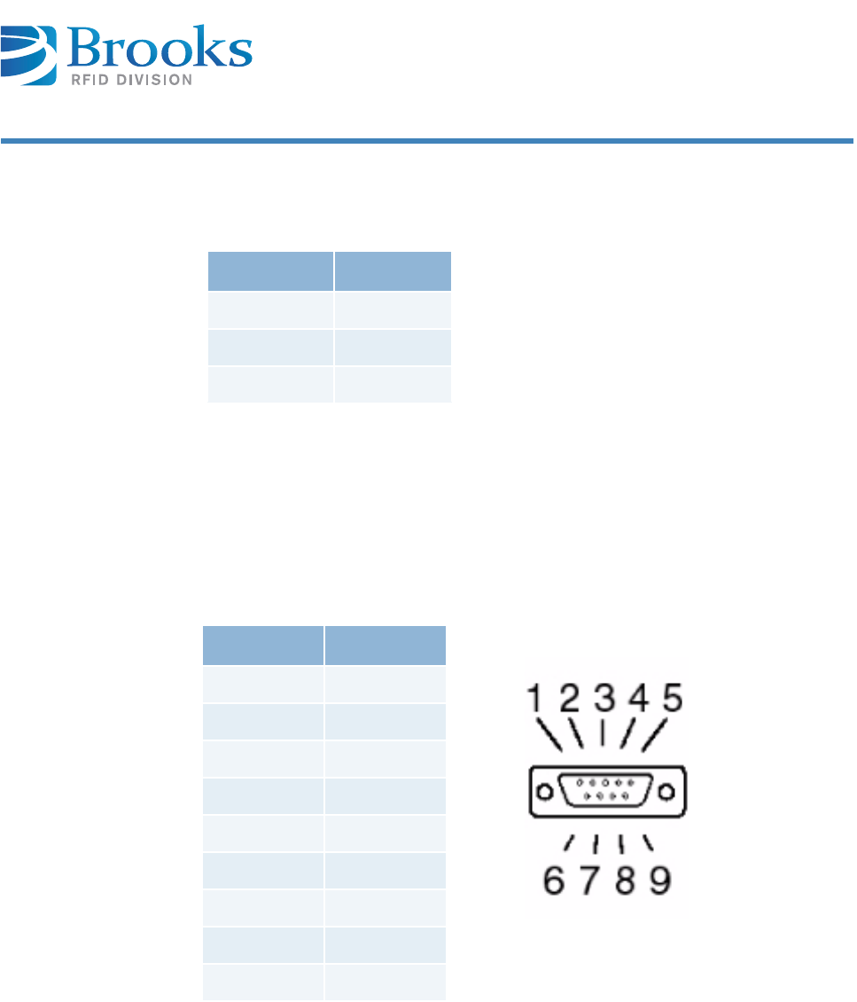
6 .7 Term ina l connect ion
The serial int er face is a Sub- D socket ( 9- pin) .
A norm al RS232 ext ension cable can be used.
Pin Signal
1GND
2+ 24 V DC
3GND
Pins 1 and 3 are bot h grounded.
Pin DB9
1NC
2TxD
3RxD
4NC
5GND
6NC
7NC
8NC
9NC
Product M an ua l - RFI D Rea de r UF7 0 Cert um 3 6
Cha pt er 6
I nst a lla t ion
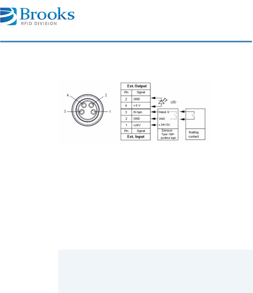
6 .8 Ex t erna l input a nd output ( opt iona l)
The following I / O versions are possible:
A digit al input and output can be connected t o each ant enna port .
A 3 wire sensor or dry cont act is possible as t he input .
The out put can operat e a LED wit hout a series resist or or directly swit ch 5 V DC.
6 .9 Com m issioning
6 .9 .1 Re quired operat in g condit ions
The following t wo condit ions m ust be fulfilled for operat ing t he device:
6 .9 .2 Para m et e rs of t he se ria l int e rfa ce
Baudrat e 57,600
Dat a bit s 8
St op bit 1
Par it y No
An ant enna m ust be connect ed correct ly t o t he reader.
Connect t he power supply and sw it ch on t he device ( if a POE is not used) .
The t ransponder m ust be locat ed within the individual reading/ wr it ing
range of t he ant enna ( for t est ing) !
Product M an ua l - RFI D Rea de r UF7 0 Cert um 3 7
Cha pt er 6
I nst a lla t ion
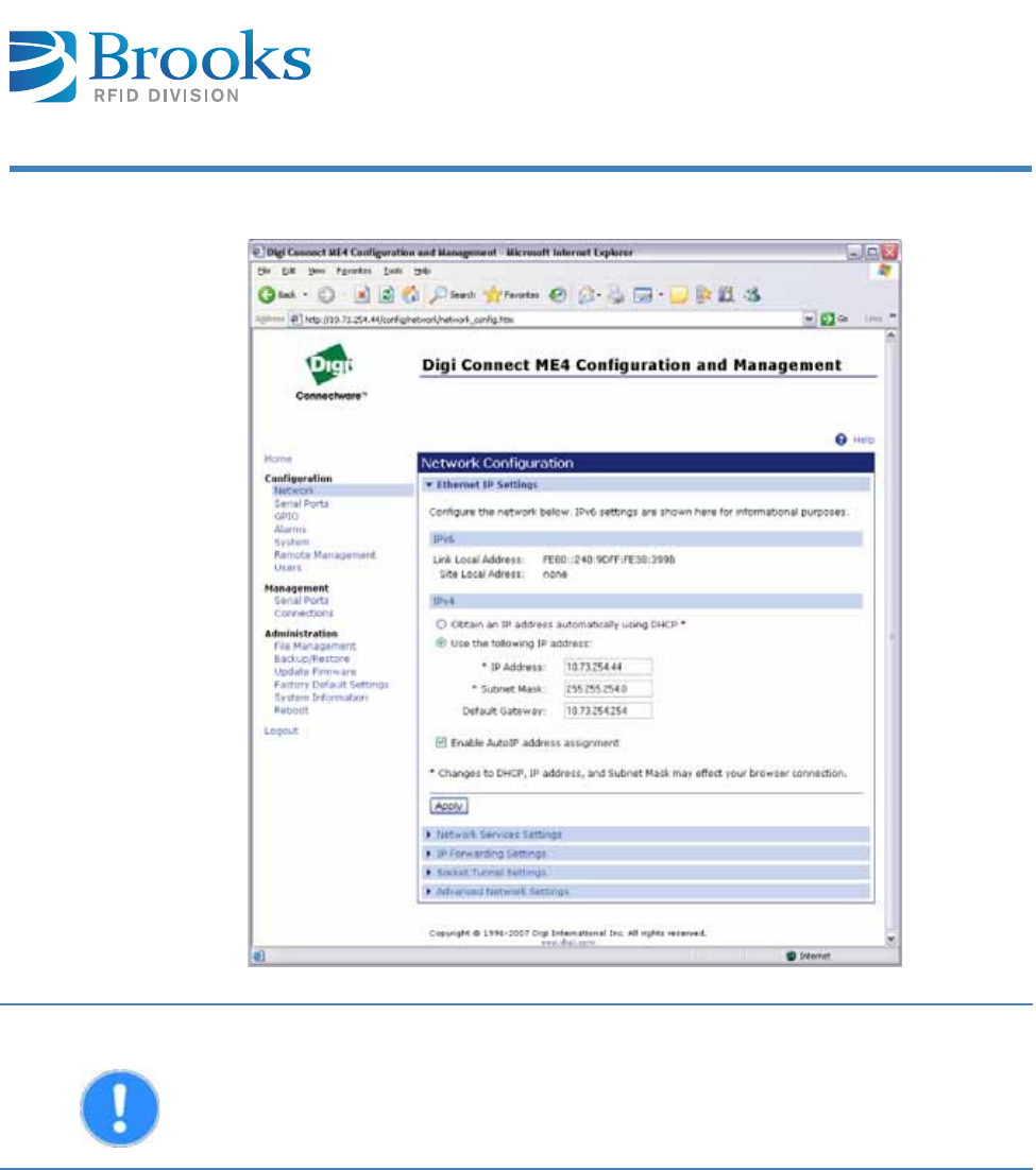
6 .9 .3 Para m et er s of t he Et he r n e t int er face
The Et hernet is connect ed via an Ethernet m odule.
Tools are available t hat allow t he Ethernet set t ings t o be configur ed.
By using Discovery Tools, all Ethernet devices locat ed in the net w ork can be
found.
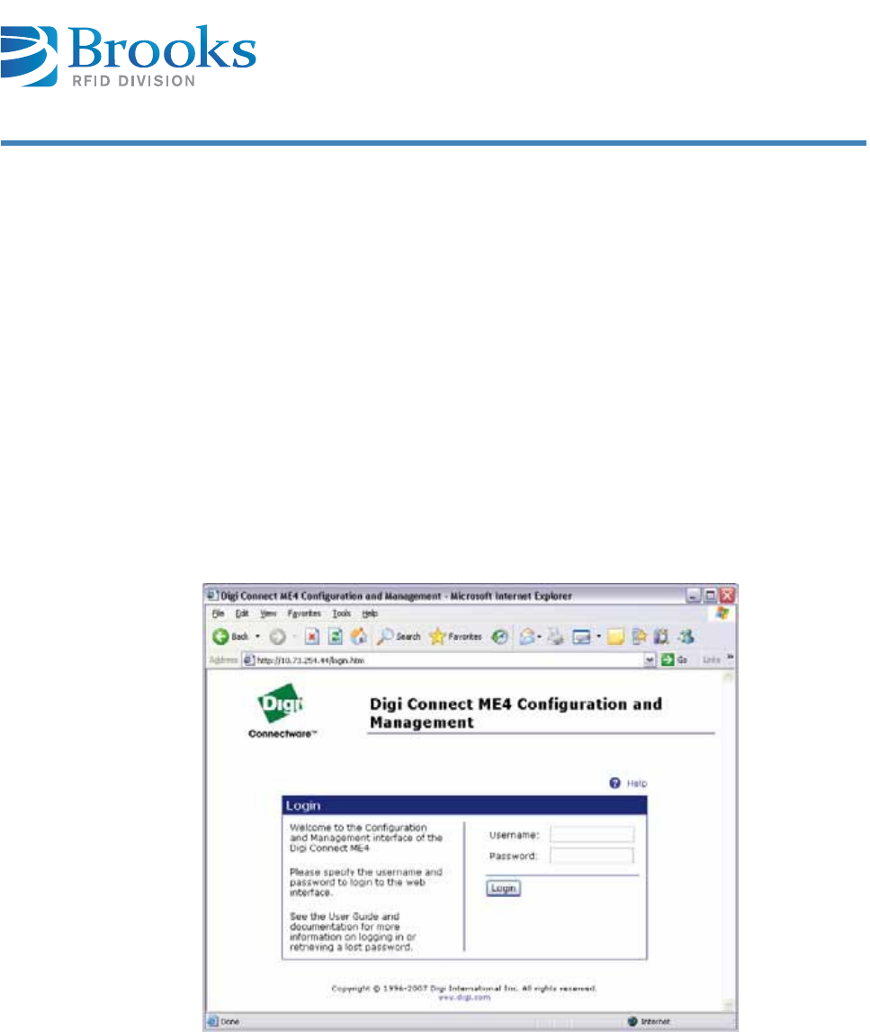
The respect ive device can be configured via a web server and a web browser via a
double click. I f t he TCP / I P address is know n, the web server can also be directly
opened in a browser also follows:
ht t p: / / xxx.xxx.xxx.xxx/
User : " r oot "
Pa ssw ord: "dbps"
xxx.xxx.xxx.xxx – current ly set I P address
Login
The I P addr ess can be set via t he " net w ork" link. The set t ings are t ransfer red wit h
the " apply" but t on and t he device is t hen reboot ed.
Product M an ua l - RFI D Rea de r UF7 0 Cert um 3 8
Cha pt er 6
I nst a lla t ion
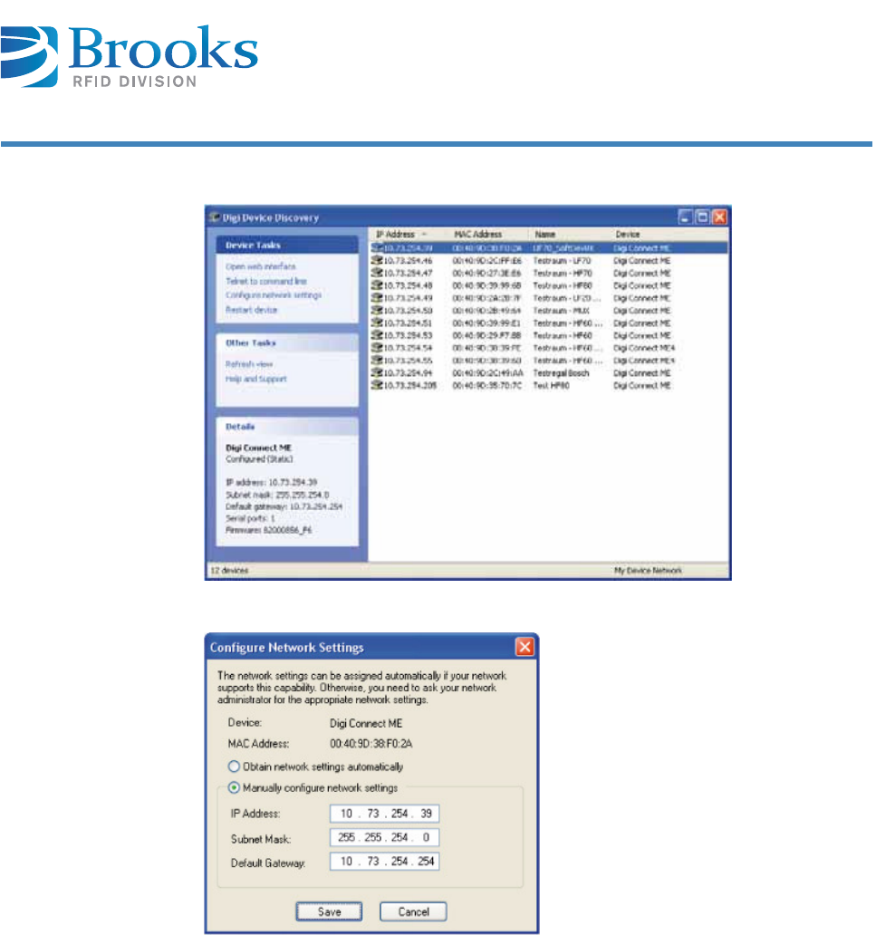
Con fig ur a t ion
Digi D e vice
Discove ry
The t ool displays all devices t hat have a Digi Connect ME. Devices t hat are not in
the sam e subnet are also displayed. The I P address can be set direct ly via
"configure net work settings". Fixed I Ps or DHCPs are possible. The web server of
the device can be accessed direct ly via the "open w eb int erface".
I M PORTAN T The "Fact ory Default Sett ings" m ust not be set under any circum st ances as t hey
are not t he fact ory set t ings of Brooks. Any ot her set t ings of t he Ethernet device
( exept t he I P address) m ust not be changed. Otherwise a fault - free
com m unicat ion cannot be guarant eed by Brooks.
Product M an ua l - RFI D Rea de r UF7 0 Cert um 3 9
Cha pt er 6
I nst a lla t ion
Select ion w in dow
I nput w indow

Product M an ua l - RFI D Rea de r UF7 0 Cert um 4 0
Cha pt er 7
Ope ra t ion
7 Operation
This chapt er gives you an overview of the following t opics:
■ Operat ing personnel
■ Com m unicat ion prot ocol ASC-I 1
■ Addit ional inform at ion
7 .1 Opera t ing personnel
7 .2 Com m unica t ion prot ocol ASC- I 1
7 .2 .1 St ruct ur e of t he com m unica t ion pr ot ocol
General r em arks:
■The com m unicat ion is done wit h ASCI I packages.
■Each device has an RS232 int erface and an opt ional Ethernet int erface t o
which an address from 0 t o E can be assigned. The device has a default
address of 0 on delivery.
■After each com m and t o t he device, a defined response is sent . We
recom m end wait ing for t his response before sending a new com m and.
CAUTI ON The UF70 Certum reader should only be operat ed by specially t rained
personnel.
I f you have doubt s about t he required qualificat ions, cont act t he m anufact urer.
Operat ing t he device wit hout special t raining can result in dam age t o t he r eader
and/ or connect ed devices.

Product M an ua l - RFI D Rea de r UF7 0 Cert um 4 1
Cha pt er 7
Ope ra t ion
7 .2 .2 Pack a ge con t en t s
General r em arks:
Each package includes a package header ( t hr ee charact ers) , a m essage ( t wo or
m ore charact ers) and t he end of t he package ( five characters) .
Pa ck age hea de r The header includes the start charact er ( one charact er) and t he package lengt h
( two charact ers)
2 st art ing charact ers and 4 lengt h byt es are sent in t he ext ended ASCI I prot ocol.
St ar t St art charact er ( ASCI I charact er ´ S´ )
Lengt h 1 High byt e package lengt h ( hexadecim al) –
ASCII characters ´ 0´ ..´ F´
Lengt h 2 Low byte package lengt h ( hexadecim al) –
ASCII characters ´ 0´ ..´ F´
Extended ASCI I form at:
St ar t 1 First st art charact er ( ASCI I charact er 'S')
St ar t 2 Second st art charact er ( ASCI I charact er 'X') for m arking
the ext ended ASCI I prot ocol
Lengt h 1 High byt e package lengt h ( hexadecim al) -
ASCII characters ´ 0´ ..´ F´
Lengt h 2 Byt e package lengt h ( hexadecim al) -
ASCII characters ´ 0´ ..´ F´
Lengt h 3 Byt e package lengt h ( hexadecim al) -
ASCII characters ´ 0´ ..´ F´
Lengt h 4 Low byt e package lengt h
( hexadecim al) - ASCI I characters ´ 0´ ..´ F´
The m essage lengt h descr ibes t he num ber of charact ers of a m essage.
Pack a ge he a der Message End of pa ck age
Pack a ge he a der
St ar t Length 1 Lengt h 2
Pack a ge he a der
St ar t 1 St art 2 Lengt h 1 Lengt h 2 Lengt h 3 Length 4
nbb

Product M an ua l - RFI D Rea de r UF7 0 Cert um 4 2
Cha pt er 7
Ope ra t ion
Me ssa ge st r uct ur e The m essage cont ains a com m and, a t arget and source address, the num ber of
the ant enna port ( Head) and t he act ual infor m at ion. The num ber of t he ant enna
port is not required for all m essages.
Com m and ASCI I charact ers ( see section Com m ands of prot ocol)
Address Tar get or source address; ASCI I charact er s '0'...’E’* )
Head Opt ional – for m essages t hat refer t o a specific
ant enna por t
I nform at ion Depends on t he com m and ( includes none, one or m ore
ASCII characters '0'...'F')
* ) The device is pre- configured wit h an address of '0' on delivery.
End of pa ck a ge The end of t he package includes an end ( 1 character) and t he checksum ( 4
charact ers)
End End charact er ASCI I character no. 13 ( hexadecim al 0D)
Checksum 1 High- byte – XOR logic for all dat a
( package header, m essage and end charact er) ; ASCI I ‘0’..’F’
Checksum 2 Low byt e – XOR logic for all data
( package header, m essage and end charact er) ; ASCI I ‘0’..’F’
Checksum 3 High byt e – addit ion of all dat a
( package header, m essage and end charact er) ; ASCI I ‘0’..’F’
Checksum 4 Low byt e – addition of all dat a
( package header, m essage and end charact er) ; ASCI I ‘0’..’F’
Me ssa ge
Com m and Addr ess Head I nfor m at ion
En d of p ack ag e
End Checksum
1
Check sum
2
Checksum
3
Checksum
4

Product M an ua l - RFI D Rea de r UF7 0 Cert um 4 3
Cha pt er 7
Ope ra t ion
7 .2 .3 Com m ands of pr ot ocol
Com m a nds
ATTEN TI ON When using t he TCP/ I P int erface opt ion, t he checksum is not used ( is not
t ran sm it t ed) .
Com m a nd De scription
X or URX Read dat a range of all EPC transponders
URY Read dat a range of t he EPC t ransponders wit h special EPC
code
MEPC scanning
URB EPC bulk reading w it h t im e specificat ion
WWrit e EPC of a single t ransponder
UWW Writ e dat a range of all EPC t ransponders
UWZ Writ e dat a range of t he EPC t ransponders wit h special EPC
code
UMW Writ e dat a range m asked of all EPC t ransponder s
UMZ Writ e dat a range m asked of t he EPC t ransponders wit h special
EPC code
UBW Erase block of all EPC transponders
UBZ Erase block of t he EPC transponders wit h special EPC code
ULW Ret rieving all EPC t ransponders
ULZ Ret rieving all EPC transponders wit h special EPC code
UKW Killing all EPC t ransponders
UKZ Killing all EPC t ransponders with special EPC code
T or UAM Activat e polling: EPC scanning
UAA Activat e polling: Read raw
UAX Activat e polling: Read dat a range
UAW Act ivate polling: Writ e dat a range

Product M an ua l - RFI D Rea de r UF7 0 Cert um 4 4
Cha pt er 7
Ope ra t ion
UAZ Activat e polling: Writ e dat a range m asked
UAB Activat e polling: Erase block of all EPC t ransponders
UAL Activat e polling: Ret rieving all EPC transponders
UAK Activat e polling: Killing all EPC t ransponders
UAR Read t ransponder rat e in t he polling operat ion
UAE St op polling
UCX Activat e polling: NXP-UCODE- G2X Read Prot ect
UCN Activat e polling: NXP-UCODE-G2X Reset Read Prot ect
UCC Activat e polling: NXP-UCODE- G2X Change EAS
UCE Activat e polling: NXP-UCODE- G2X EAS Alarm
UFW Set filt er dat a
UFR Read filt er dat a
UFP Set filt er
UFG Read filter st at us
UGL Read out list of radio profiles
UGP Determ ine act ive radio profile
UPP Set t he active radio profile
UNH Perform hardware r eset
N or UNR Perform software reset
UPE Load factory default values
FRequest param et er
PSet param et er
UGK Read t he num ber of t he act ive param et er set
UPK Set t he num ber of t he act ive param et er set
UGD Read t he num ber of t he default param eter set
UPD Set t he num ber of t he default param et er set
BSensor st at us
OSet t ing t he out put s
QQueries of out put s ( stat us)
Com m a nd De scription
Product M an ua l - RFI D Rea de r UF7 0 Cert um 4 5
Cha pt er 7
Ope ra t ion
EError m essage
HHeart beat ( request serial num ber)
V or UVR Request soft ware version
UGT Read UTC t im e
UPT Set UTC t im e
Com m a nd De scription

Product M an ua l - RFI D Rea de r UF7 0 Cert um 4 6
Cha pt er 7
Ope ra t ion
Me ssa ge it e m s
The 4 byt e access word is required t o access t he various m em ory areas of t he
EPC t ransponder. The LSB byt e is t ransm it ted first during t he t ransm ission. The
dat a are int erpret ed in HEX form at . That is, t wo ASCI I charact ers in t he m essage
equal one byt e of dat a in HEX form at .
Exam ple:
0x01020304
ASCII st ring: "04030201"
2 byt es t im e in m illiseconds specifying how long t o read. The LSB byt e is
transm it t ed first during t he t ransm ission. The dat a are int erpret ed in HEX form at.
That is, t wo ASCI I charact ers in t he m essage equal one byt e of dat a in HEX
form at .
Exam ple:
0x0064 ( 100 m s)
ASCI I st ring "6400"
Com m and of the m essage. See t able in chapt er Com m ands of prot ocol.
Dat a words ( 2 byt es) are always read or writ t en. The dat a ar e interpret ed in HEX
form at. That is, t wo ASCI I charact ers in t he m essage describe one byt e of
transponder dat a in HEX form at .
Exam ple:
HEX transponder dat a: 0x12, 0x34, 0x56, 0x78 ( 2 dat a wor ds)
ASCII t ransm ission: 0x31, 0x32, 0x33, 0x34, 0x35, 0x36,
0x37, 0x38
Transm it t ed ASCI I st ring: "12345678"
Access w or d 8 byt es
Bulk t im e 4 byt es
CMD 1 - 3 byt e s
Da t a w ords 2 t o N * 4 byt e s

Product M an ua l - RFI D Rea de r UF7 0 Cert um 4 7
Cha pt er 7
Ope ra t ion
A net work configurat ion t hat det erm ines if t he st at ic net work address is being
used or if t he DHCP server assigns t he net work address.
"0" DHCP is not act ive, use stat ic netw ork address
"1" DHCP is act ive; obt ain network address from the DHCP server
When polling, t he dir ection flag shows if a t ransponder ent er s or leaves t he field.
The display t hat a t ransponder leaves t he field can be act ivat ed via param eter
0x29. The dat a ar e int erpret ed in HEX for m at . That is, t wo ASCI I charact ers in
the m essage equal one byt e of dat a in HEX for m at .
Va lu e s:
"00" ( 0x00) The t ransponder leaves t he field
"80" ( 0x80) The RSSI value changed The t ransponder m oved wit hin t he field
"FF" ( 0xFF) The transponder ent ers t he field
With t he UHFI 20 soft ware version ( firm ware 2.x) , t he EPC code has a flexible
lengt h n from 0 t o 31 data words ( 2 byt es dat a) . An n byt e is placed before t he
actual EPC code and corresponds t o t he quantit y of EPC dat a words. The EPC code
is t ransferred so t hat t he LSB byt e is t ransm it ted first. The dat a are int erpret ed in
HEX form at. That is, t wo ASCI I charact ers in t he m essage equal one byt e of data
in HEX form at . The follow ing applies t o t he num ber of EPC dat a words:
0< = n< = 31
Exam ple:
ASCII st ring: "060C0B0A090807060504030201"
Num ber of EPC dat a words: 0x06
EPC: 0x0102030405060708090A0B0C
DH CP 1 byt e
D ir e ct io n 2 byt es
EPC ( 2 n+ 1 ) * 2 by t es

Product M an ua l - RFI D Rea de r UF7 0 Cert um 4 8
Cha pt er 7
Ope ra t ion
The ext ension flag det erm ines which inform at ion is included in t he recognized
EPC t ransponder. The Ex flag is set by param et er 0x76. The dat a are int erpreted
in HEX form at. That is, t wo ASCI I charact ers in t he m essage equal one byt e of
dat a in HEX form at.
Va lu e s:
0x00 do not t ransm it extensions
0x01 only t ransm it ant enna port
0x02 only t ransm it RSSI value
0x03 transm it ant enna port and RSSI
0x04 t ransm it tim e st am p
0x05 transm it t im e st am p and ant enna por t
0x06 t ransm it t im e st am p and RSSI value
0x07 transm it t im e st am p, RSSI value and ant enna port
0x08 transm it t ransponder prot ocol cont rol word
0x09 transm it ant enna port and t ransponder prot ocol cont rol word
0x0A transm it RSSI value and prot ocol cont rol word
0x0B t ransm it ant enna port , RSSI value and prot ocol cont rol word
0x0C t ransm it t im e stam p and prot ocol cont rol word
0x0D transm it t im e st am p, ant enna port and prot ocol control word
0x0E transm it t im e st am p, RSSI and prot ocol control w ord
0x0F transm it t im e st am p, RSSI , ant enna port and prot ocol cont rol word
I f and which ext ensions are transm it t ed for each det ect ed EPC t ransponder is
defined by the Ex flag. The dat a are int erpret ed in HEX form at. That is, t wo ASCI I
charact ers in t he m essage equal one byt e of data in HEX form at. The act ivat ed
ext ensions are transferred in t he following order:
2 ASCII charact ers antenna port
2 ASCII charact ers RSSI value
8 ASCII charact ers UTC t im e st am p ( LSB byt e is t ransm it t ed first )
4 or 8 ASCI I character prot ocol word as applicable including XPC_W1 and
XPC_W2
Ex flag 2 byt es
Ex t e nsio n 0 - 1 2 byt e s

Product M an ua l - RFI D Rea de r UF7 0 Cert um 4 9
Cha pt er 7
Ope ra t ion
The filt er bit s required for t he developm ent of a filter are defined in HEX form at in
a filt er m ask. That is, t wo ASCI I charact ers in t he m essage equal one byt e of dat a
in HEX form at. The LSB byte of t he filt er m ask is t ransm it ted first .
Exam ple: N= 3
Num ber of m ask bit s: 18
Filt er m ask: "0x03FEFE"
Transm ission: "FEFE03"
The filt ers defined for filtering are num bered consecut ively from 0 t o 31.
Va lu e s:
"00" – Filt er 0
…
"1F" – Filt er 31
The response of t he reader can be accom plished in several fram es ( e.g. if m any
transponders w ere scanned) . The fram e I D that is sent indicat es how m any
response m essages follow. Short responses t hat consist only of a single fram e
then always have t he fram e I D "00". Messages consist ing of m ult iple fram es
should be fully received and assem bled by t he host before they are processed.
The data are int erpret ed in HEX form at. That is, t wo ASCI I charact ers in t he
m essage equal one byt e of dat a in HEX form at .
Num ber of t he ant enna port ( 0 – 4) .
"0" read on all antenna port s
"1"- " 4" single ant enna port
Filt er m a sk N * 2 byt es
Filt er n um be r 2 byt es
Fra m e I D 2 byt es
He a d I D 1 byt e

Product M an ua l - RFI D Rea de r UF7 0 Cert um 5 0
Cha pt er 7
Ope ra t ion
The bit- orient ed m ask det erm ines what dat a will act ually be overwrit t en in t he
m asked w rite. The m ask has t he sam e lengt h as t he dat a t o be writ t en and actual
dat a is only writ t en in t he places where a 1 is locat ed in t he m ask. The m ask is
passed in t he sam e order and lengt h as t he m asked data t o be writ t en.
Exam ple:
N= 1 describe a data w ord m asked
Transponder cont ent : 0x5678
New dat a: 0x1234
Mask: 0x0F0F
new t ransponder content : 0x5274
The m em ory areas of t he EPC transponder are addr essed by 4 byt e word
pointers. The LSB byt e is t ransm itted fir st during t he t ransm ission. The dat a are
int erpreted in HEX form at . That is, two ASCI I characters in t he m essage equal
one byt e of dat a in HEX form at. The exact m em ory dist ribut ion can be derived
from t he EPC Global standard.
The EPC t ransponder has m ult iple m em ory banks, which are addr essed by
num ber. The exact m em ory st ruct ure can be derived from t he EPC Global
st andard chapter. The dat a are int er pret ed in HEX form at . That is, t wo ASCI I
charact ers in t he m essage equal one byt e of dat a in HEX form at.
Va lu e s:
"00" ( 0x00) Reserved
"01" ( 0x01) EPC
"02" ( 0x02) TI D
"03" ( 0x03) User
The num ber of dat a words ( 1 dat a word consists of 2 byt es), which are read and
writ t en, are hereby defined.
The data are int erpret ed in HEX form at. That is, t wo ASCI I charact ers in t he
m essage equal one byt e of dat a in HEX form at .
Ma sk N * 4 by t es
Me m or y a ddre ss 8 byt es
Me m or y ba nk 2 byt es
N um be r of da t a w or ds 2 byt es

Product M an ua l - RFI D Rea de r UF7 0 Cert um 5 1
Cha pt er 7
Ope ra t ion
The use of a defined filt er can hereby be enabled or disabled.
Va lu e s:
"00" – Filt er off
"FF" – Filt er on
Displays t he current st at us of t he out put s at t he corresponding ant enna port
( Head I D) . The inform ation unit "Out put st at e" includes t he stat us of each out put
of an ant enna port . I n t he case of querying t he st at us of all out put s of t he reader,
the " Out put St ate" cont ains t he stat us of all 4 out put s ( 1 per head) . The st at us is
represent ed as 1 byt e for each head.
Va lu e s:
0 – Output OFF
1 – Output ON
2 – Output flashes
3 – unchanged ( query only! )
Num ber of t he param et er. Two ASCI I characters ( 2 byt es) display t he param et er
num ber in HEX form at .
Exam ple:
Param et er 20 0x14 "14"
Value of the param eter. Two ASCI I charact ers ( 2 byt es) specify t he value of t he
param eter in HEX form at.
Exam ple:
Value 192 0xC0 " C0"
On/ Off 4 byt es
Out put st a t e 1 - 4 byt e s
Par a m e t e r n o. 2 byt es
Par a m e t e r v alue 2 byt es

Product M an ua l - RFI D Rea de r UF7 0 Cert um 5 2
Cha pt er 7
Ope ra t ion
I f a t ransponder m ust be locked, t he area of the t ransponder t o be locked can be
specified by t he payload. The LSB byte is t ransm itted fir st during the
transm ission. Dat a ( 3 bytes) are in HEX form at . That is, t wo ASCI I characters in
the m essage equal one byt e of dat a in HEX for m at . The exact st ruct ure can be
derived from t he EPC Global st andar d chapt er "Lock" .
Exam ple:
Access area wit h Perm alock= 1 lock
Payload 0x0300C0
Transfer Protocol " C00003"
Radio profiles realized in t he reader, which are num bered from 0 t o 4.
Radio profiles:
"00" – Tx: 40kbps/ Rx: 80kbps/ FM0
"01" – Tx: 40kbps/ Rx: 40kbps/ Miller2
"02" – Tx: 40kbps/ Rx: 160kbps/ FM0
"03" – Tx: 40kbps/ Rx: 80kbps/ Miller2
"04" – Tx: 40kbps/ Rx: 40kbps/ Miller4 ( default set t ing)
Address of t he device ( "0" .. " E") .
The default address of t he card is "0" on delivery.
I f a t ransponder m ust be m ade unreadable ( or possibly also recom m issioned) , 3
so- called recom m ission bit s m ust be transferred. The value and significance of
the recom m ission bits depend on t he t ype of t ransponder. The 3 bit s are
int erpr et ed as one byt e data in HEX form at. That is, t wo ASCI I charact ers in t he
m essage equal one byt e of dat a in HEX form at . The precise significance of t he 3
recom m ission bit s can be seen in t he docum ent at ion of t he EPC t ransponder and
the EPC global standard chapt er " Kill" .
Pay loa d 6 byt e s
Profile nu m ber 2 byt es
Re a de r I D 1 byt e
RECOM M I SSI ON 2 byt es

Product M an ua l - RFI D Rea de r UF7 0 Cert um 5 3
Cha pt er 7
Ope ra t ion
This feat ure is not used for t he single reader. This code is always " 0000".
The result flag delivers inform at ion on whether an action was com plet ed
successfully. The dat a are int er pret ed in HEX form at. That is, t wo ASCI I
charact ers in t he m essage equal one byt e of dat a in HEX form at.
Va lu e s:
"00" ( 0x00) no errors occurred
> 0x00 an error occurred
Displays t he cur rent st at us of t he sensor at the corresponding ant enna port ( Head
I D) .
Value 0 Sensor is uncovered ( open)
Value 1 Sensor is covered ( closed)
Cont ains t he 4- byt e serial num ber of t he reader.
The serial num ber is also show n on t he label of t he reader.
Charact er string w it h t he soft ware version of the reader. The display is in HEX
form at. This m eans t hat t he 12- 16 charact ers of t he ASCI I charact er st ring
describe t he 6- 8 byt es of t he soft ware version in HEX form at.
Exam ple:
v0554846493230
0x55 0x48 0x46 0x49 0x32 0x30
= " UHFI 20"
Re sponse code 4 byt es
Re su lt 2 byt e s
Sensor st at e 1 byt e
Seria l n um be r 4 byt es
Soft w a r e ver sion 6 - 8 byt e s

Product M an ua l - RFI D Rea de r UF7 0 Cert um 5 4
Cha pt er 7
Ope ra t ion
The t ransponder it self also delivers an error code, which is also transm it t ed. The
dat a are int erpret ed in HEX form at . That is, t wo ASCI I charact ers in t he m essage
equal one byt e of dat a in HEX form at .
Va lu e s:
"00" ( 0x00) no errors occurred
> 0x00 an error occurred
The Unix t im e code ( UTC) describes t he seconds t hat have passed since 1.1.1970
0: 00: 00. The Unix t im e code ( UTC) is t he sam e worldwide for a specific t im e. The
4 byt es of UTC are t ransm it ted in hex form at as 2 ASCI I charact ers per byt e. The
LSB byt e is t ransm it t ed first .
Tran spon der e rr or code 2 byt es
UTC 8 byt es

Product M an ua l - RFI D Rea de r UF7 0 Cert um 5 5
Cha pt er 7
Ope ra t ion
X or URX - Rea d
da t a a r ea
The X com m and st art s t he reading of a defined dat a range of t he current EPC
transponder.
Several EPC t ransponders can be locat ed in t he reading ar ea of t he ant enna when
using t his com m and.
1) These dat a are displayed in t he order list ed for each ident ified EPC
transponder.
2) The response of t he t ransponder is opt ional and only appears at result "00" .
3) The result and Ex flag is only available in t he first t ransm it t ed m essage in
m essages wit h several fram es.
Exam ple: Read access password ( no t ransponder is present )
> > X0100000000000200000002
< < x0000A Result " 0A" no EPC t ransponder is present
Exam ple: Read access password ( 2 t ransponders)
> > X0100000000000200000002
< < x0000001
0106010203040506070808080909000200000000
01060B0C090A0708050603040102000200000000
Host re a der
CMD Re a de r I D He ad I D Access w or d Me m or y ba nk Me m or y
addr e ss
N u m ber of
da t a w ords
X
URX
1 byte 1 by t e 8 byt es 2 bytes 8 byt es 2 bytes
Re a de r host
Ov e r head r esponse t e le gra m 2 ) D a t a of t h e pa r t icipat ing EPC t ra n spon de r s1 ) 2 )
CMD Rea de r
I D
Fra m e
I D Re su lt 3 ) Ex
fla g3 )
Ex t en-
sions EPC
Tra ns-
pon de r
error
code
N u m ber
N da t a
w ords
Dat a
w ords
x
urx
1 byte 2 bytes 2 byt es 2 byt es 0- 12
by t es
( 2n+ 1) *
2 byt es
2 byt es 2 by t es N* 4
by t es

Product M an ua l - RFI D Rea de r UF7 0 Cert um 5 6
Cha pt er 7
Ope ra t ion
Exam ple: Read access password ( m any t ransponders)
> > X0100000000000200000002
< < x0020001
0106480000000000000000000000000200000000
0106010000000000000000000000000200000000
0106060000000000000000000000000200000000
0106270000000000000000000000000200000000
< < x001
0106190000000000000000000000000200000000
0106500000000000000000000000000200000000
0106470000000000000000000000000200000000
0106170000000000000000000000000200000000
0106090000000000000000000000000200000000
0106100000000000000000000000000200000000
0106310000000000000000000000000200000000
0106390000000000000000000000000200000000
0106020000000000000000000000000200000000
0106460000000000000000000000000200000000
0106410000000000000000000000000200000000
0106070000000000000000000000000200000000
01062300000000000000
< < x000
00000000000200000000
0106380000000000000000000000000200000000
0106400000000000000000000000000200000000
0106180000000000000000000000000200000000
0106280000000000000000000000000200000000
0106420000000000000000000000000200000000
0106240000000000000000000000000200000000
0106290000000000000000000000000200000000
0106080000000000000000000000000200000000
0106110000000000000000000000000200000000
0106160000000000000000000000000200000000
0106260000000000000000000000000200000000
0106490000000000000000000000000200000000

Product M an ua l - RFI D Rea de r UF7 0 Cert um 5 7
Cha pt er 7
Ope ra t ion
URY – Re ad dat a
ar ea ( de fine d EPC
code)
The URY com m and st art s t he reading of a defined dat a range of t he current EPC
transponders w hich have a defined EPC code. Several EPC t ransponders can be
locat ed in t he reading area of t he ant enna when using t his com m and.
1) These dat a are displayed in t he order list ed for each ident ified EPC
transponder.
2) The response of t he t ransponder is opt ional and only appears at result "00" .
3) The result and Ex flag is only available in t he first t ransm it t ed m essage in
m essages wit h several fram es.
Exam ple: Read access password
> > URY01060102030405060708090A0BCD00000000000200000002
< < ur y000000101060102030405060708090A0BCD000200000000
Host r eader
CMD Re a der
I D
He a d
I D EPC Acce ss
w ord
Me m or y
ba n k
Me m or y
addr e ss
N u m be r
of da t a
w or ds
URY 1 by t e 1 byt e ( 2n+ 1) * 2 byt es 8 byt es 2 byt es 8 byt es 2 byt es
Re a de r host
Ove rhea d response t e legr am 2 ) Dat a of t he pa rt icipa t ing EPC t r a nspon de rs1 ) 2 )
CMD Rea de r
I D
Fram e
I D Re sult 3 ) Ex
fla g 3 )
Ex t en-
sions EPC
Tra n s-
ponder
err or
code
N u m be r
N da t a
w ords
Dat a
w ords
ury 1 byt e 2 byt es 2 byt es 2 byt es 0- 12
by t es
( 2n + 1 ) *
2 byt es
2 byt es 2 byt es N* 4
by t es

Product M an ua l - RFI D Rea de r UF7 0 Cert um 5 8
Cha pt er 7
Ope ra t ion
M - EPC sca nn ing The M com m and st art s t he scanning of t he EPC transponder locat ed in the
activat ed antenna locat ed in t he r ead area.
1) These dat a are displayed in t he order list ed for each ident ified EPC
transponder.
2) The response of t he t ransponder is opt ional and only appears at result "00" .
3) The result and Ex flag is only available in t he first t ransm it t ed m essage in
m essages wit h several fram es.
Exam ple:
> > M01
< < m 0010001 Fram e-I D "01"; result "00" and Ex flag "01"
0106470000000000000000000000
0106270000000000000000000000
0106110000000000000000000000
0106490000000000000000000000
0106100000000000000000000000
0106230000000000000000000000
0106420000000000000000000000
0106080000000000000000000000
0106310000000000000000000000
0106290000000000000000000000
0106120000000000000000000000
0106
t he m issing 12 byt es are included in t he next m essage
< < m 000
250000000000000000000000
0106480000000000000000000000
0106410000000000000000000000
0106380000000000000000000000
Host re a de r
CMD Re a de r I D Hea d I D
M1 byt e 1 byt e
Re a de r host
Ove rhea d response t e legr am 2 ) Dat a of t he pa rt icipat ing EPC
t r a nsp on de r s1 ) 2 )
CMD Re a der
I D
Fra m e
I D Re su lt 3 ) Ex fla g3 ) Ex t ensions EPC
m 1 byt e 2 byt es 2 byt es 2 bytes 0- 12 byt es (2n+ 1) * 2 byt es

Product M an ua l - RFI D Rea de r UF7 0 Cert um 5 9
Cha pt er 7
Ope ra t ion
0106280000000000000000000000
0106030000000000000000000000
0106170000000000000000000000
0106190000000000000000000000
0106400000000000000000000000
0106050000000000000000000000
0106090000000000000000000000
0106010000000000000000000000
0106240000000000000000000000
0106460000000000000000000000
0106260000000000000000000000
0106180000000000000000000000
0106390000000000000000000000
0106060000000000000000000000
> > M01
< < m 0000A Result 0x0A, since no transponder is available
> > URM01
< < ur m 0000A Result 0x0A, since no t ransponder is available
> > URM01
< < ur m 0000001 Fram e-I D "00"; result "00" and Ex flag "01"
01060B0C090A0708050603040102

Product M an ua l - RFI D Rea de r UF7 0 Cert um 6 0
Cha pt er 7
Ope ra t ion
URB – EPC
Bulk r eadin g
The com m and URB start s a reading of EPC t ransponders over a pr edet er m ined
period of tim e. The EPC of all detected t ransponders is report ed after t he
com plet ion of t he t im e.
1) These dat a are displayed in t he order list ed for each ident ified EPC
transponder.
2) The response of t he t ransponder is opt ional and only appears at result "00" .
3) The result and Ex flag is only available in t he first t ransm it t ed m essage in
m essages wit h several fram es.
Exam ple:
> > URB016400 ( read 100 m s ! ! )
< < ur b0000001
0106010203040506070808080909
01060B0C090A0708050603040102
0106BBCC99AA7788556633441122
> > URB010064
< < ur b0000A Result 0x0A, since no t ransponder is available
Host r eader
CMD Re a de r I D He a d I D Bulk t im e
URB 1 byt e 1 byt e 4 byt es
Re a de r host
Ove rhea d response t e le gr a m 2 ) Da t a of t he pa r t icipa t in g EPC t ran sponders1 ) 2 )
CMD Re a der
I D
Fra m e
I D Re su lt 3 ) Ex
fla g3 )
Ex t e n-
sions EPC
Tra n s-
ponder
err or
code
N u m be r
N dat a
w or ds
Dat a
w or ds
urb 1 byte 2 byt es 2 byt es 2 byt es 0- 12
by t es
( 2n + 1) *
2 byt es
2 byt es 2 bytes N* 4
by t es

Product M an ua l - RFI D Rea de r UF7 0 Cert um 6 1
Cha pt er 7
Ope ra t ion
W – W rit e EPC code The W com m and start s t he descript ion of the EPC of a present EPC t ransponder.
Only one EPC transponder should be locat ed in the w rite area of t he antenna
when using this com m and.
1) The t ransponder her e delivers as a response t he EPC code w hich was
previously program m ed.
2) The response of t he t ransponder is opt ional and only appears at result "00" .
Exam ple: Overwrit e EPC t ransponder wit h a new EPC code
> > M01 ( read old EPC code)
< < m 000000101060102030405060708090A0BCD
> > W0100000000060102030405060708090A0B0C
< < w000000101060102030405060708090A0BCD8B
> > M01 ( read new EPC code)
< < m 000000101060102030405060708090A0B0C
Exam ple: Several t ransponder s are in t he field; t he act ion is t herefore incor rect
> > W0100000000060102030405060708090A0B0C
< < w0000B Result 0x0B
Host re a de r
CMD Reader I D H e a d I D Acce ss w ord EPC
W 1 byt e 1 byt e 8 byt es (2n+ 1) * 2 byt es
Re a de r host
Ove rhea d response t e le gra m Dat a of t he pa rt icipa t ing EPC t r ansponde rs2 )
CMD Rea de r
I D
Fra m e
I D Re sult Ex
fla g Ex t e nsion s EPC1 ) Tra n sp on de r
err or code
w 1 byt e 2 byt es 2 bytes 2 byt es 0- 12 byt es ( 2n+ 1) * 2 bytes 2 bytes

Product M an ua l - RFI D Rea de r UF7 0 Cert um 6 2
Cha pt er 7
Ope ra t ion
UW W – W rit e da t a
ra nge of a ll EPC
t r a nsp on de r s
The UWW com m and st art s t o overwrit e t he defined dat a range of all EPC
transponders locat ed in t he field. Several EPC t ransponders can be locat ed in t he
write area of t he ant enna when using t his com m and.
1) These dat a are displayed in t he order list ed for each ident ified EPC
transponder.
2) The response of t he t ransponder is opt ional and only appears at result "00" .
3) The result and Ex flag is only available in t he first t ransm it t ed m essage in
m essages wit h several fram es.
Exam ple: Overwrit e EPC t ransponder wit h a new EPC code
> > UWW01000000000102000000060102030405060708090A0B0C
< < uw w000000101060B0C090A070805060304010200
Cont rol reading:
> > M01
< < m 0000001
01060B0C090A0708050603040102
Exam ple: Overwrit e several EPC transponders wit h a new EPC code
> > UWW01000000000102000000060102030405060708090A0B0C
< < uw w0000001
010600000000C006D9DDB233083000
010600000000C006D9DDB233083000
0106BBCC99AA778855663344112200
Cont rol reading:
> > M01
< < m 0000001
01060B0C090A0708050603040102
01060B0C090A0708050603040102
Host re a de r
CMD Rea de r
I D H e a d I D Acce ss
w ord
Me m or y
ba n k
Me m or y
addre ss
N u m be r of N
da t a w ords
Dat a
w ords
UWW 1 byt e 1 byt e 8 byt es 2 byt es 8 byt es 2 byt es N* 4
by t es
Re a de r host
Ove rhea d response t e legr am 2 ) Dat a of t he pa rt icipa t ing EPC
t r a nsp on de r s1 ) 2 )
CMD Rea de r
I D
Fra m e
I D Re su lt 3 ) Ex fla g3 ) Ex t en sio ns EPC Tr ansponde r
err or code
uww 1 byt e 2 byt es 2 byt es 2 byt es 0- 12 byt es ( 2n+ 1) * 2 byt es 2 byt es

Product M an ua l - RFI D Rea de r UF7 0 Cert um 6 3
Cha pt er 7
Ope ra t ion
01060B0C090A0708050603040102
EPC: 02010403060508070A090C0B
EPC: 02010403060508070A090C0B
EPC: 02010403060508070A090C0B
Exam ple: Wr it e EPC t ransponder access code
> > UWW0100000000000200000002FFFFFFFF
< < uww00000010106BBCC99AA778855663344112200
Cont rol reading:
> > X01FFFFFFFF000200000002
< < x00000010106BBCC99AA77885566334411220002FFFFFFFF

Product M an ua l - RFI D Rea de r UF7 0 Cert um 6 4
Cha pt er 7
Ope ra t ion
UW Z – W rit e dat a
ra nge of a ll EPC-
t r a nsp on de r s
( defin ed EPC code)
The UWZ com m and st art s t o overwrite t he defined dat a range of all EPC
transponders locat ed in t he field t hat have a defined EPC code. Several EPC
transponders can be locat ed in t he writ e area of t he ant enna when using t his
com m and.
1) These dat a are displayed in t he order list ed for each ident ified EPC
transponder.
2) The response of t he t ransponder is opt ional and only appears at result "00" .
3) The result and Ex flag is only available in t he first t ransm it t ed m essage in
m essages wit h several fram es.
Exam ple: Overwrite several EPC t ransponder s wit h the sam e EPC code
> > UWZ01060B0C090A0708050603040102000000000102000000060102030
405060708090A0B0C
< < uw z000000101060B0C090A070805060304010200
Host re a de r
CMD Rea der
I D
He a d
I D EPC Access
w ord
Me m or y
ba n k
Me m or y
addre ss
N u m ber
N da t a
w ords
Dat a
w ords
UWZ 1 byt e 1 byt e ( 2n+ 1) * 2
by t es
8 byt es 2 byt es 8 byt es 2 byt es N* 4
by t es
Re a de r host
Overh e ad re sp on se t ele gr a m 2 ) Dat a of t he pa rt icipa t ing EPC
t r a nsp on de r s1 ) 2 )
CMD Rea der
I D
Fra m e
I D Re su lt 3 ) Ex fla g3 ) Ex t e n sion s EPC Tr a nsponder
error code
uwz 1 byte 2 byt es 2 byt es 2 byt es 0- 12 byt es ( 2n+ 1) * 2
by t es
2 bytes

Product M an ua l - RFI D Rea de r UF7 0 Cert um 6 5
Cha pt er 7
Ope ra t ion
Cont rol reading:
> > M01
< < m 0000001
01060B0C090A0708050603040102
EPC: 02010403060508070A090C0B
> > M01
< < m 0000001
01060102030405060708090A0B0C
01060102030405060708090A0B0C
01060102030405060708090A0B0C
EPC: 0C0B0A090807060504030201
EPC: 0C0B0A090807060504030201
EPC: 0C0B0A090807060504030201
> > UWZ01060102030405060708090A0B0C000000000102000000061122334
45566778899AABBCC
< < uw z000000101060102030405060708090A0B0C00
> > M01
< < m 0000001
0106BBCC99AA7788556633441122
01060102030405060708090A0B0C
01060102030405060708090A0B0C
> > UWZ01060102030405060708090A0B0C00000000010200000006112233445
566778899AABBCC
< < uw z000000101060102030405060708090A0B0C00
> > UWZ01060102030405060708090A0B0C00000000010200000006112233445
566778899AABBCC
< < uw z000000101060102030405060708090A0B0C00
> > UWZ01060102030405060708090A0B0C00000000010200000006112233445
566778899AABBCC
< < uw z0000A
> > M01
< < m 0000001
0106BBCC99AA7788556633441122
0106BBCC99AA7788556633441122
0106BBCC99AA7788556633441122
EPC: 2211443366558877AA99CCBB
EPC: 2211443366558877AA99CCBB
EPC: 2211443366558877AA99CCBB

Product M an ua l - RFI D Rea de r UF7 0 Cert um 6 6
Cha pt er 7
Ope ra t ion
UMW – W rit e da t a
ra nge of a ll EPC
t r a nsp on de r s
m ask e d
The UMW com m and start s t o overwrite t he defined dat a range of all EPC
transponders locat ed in t he field. Several EPC t ransponders can be locat ed in t he
write area of t he ant enna when using t his com m and.
1) These dat a are displayed in t he order list ed for each ident ified EPC
transponder.
2) The response of t he t ransponder is opt ional and only appears at result "00" .
3) The result and Ex flag is only available in t he first t ransm it t ed m essage in
m essages wit h several fram es.
Exam ple: The EPC t ransponder m asks 1 data w ord of t he EPC code, rewr it e
> > M01
< < m00000010106BBCC99AA7788556633441122
EPC: 2211443366558877AA99CCBB
> > UMW01000000000102000000011111FFFF
< < um w00000010106BBCC99AA778855663344112200
> > M01
< < m00000010106BBCC99AA7788556633441111
EPC: 1111443366558877AA99CCBB
Exam ple: The EPC transponder m asks 2 dat a words of t he EPC code, rewrit e
> > UMW0100000000010200000002AABBCCDD0F0F0F0F
< < um w00000010106BBCC99AA778855663344111200
> > M01
< < m 00000010106BBCC99AA778855663C4D1A1B
EPC: 1B1A4D3C66558877AA99CCBB
Host re a de r
CMD Reade r
I D
He a d
I D
Acce ss
w or d
Me m or y
ba n k
Me m or y
addre ss
N um be r of
da t a w ords
Dat a
w ords M ask
UMW 1 byte 1 byt e 8 byt es 2 byt es 8 bytes 2 byt es N* 4 bytes N* 4 byt es
Re a de r host
Ove rhea d response t e le gr a m 2 ) Dat a of t he pa rt icipa t ing EPC
t r a nsp on de r s1 ) 2 )
CMD Rea de r
I D
Fra m e
I D Re sult 3 ) Ex flag3 ) Ex t e nsio ns EP C Tra n spon der
err or code
um w 1 byt e 2 byt es 2 byt es 2 bytes 0- 12 byt es ( 2n+ 1) * 2 byt es 2 bytes

Product M an ua l - RFI D Rea de r UF7 0 Cert um 6 7
Cha pt er 7
Ope ra t ion
UMZ – W rit e da t a
ra nge of a ll EPC-
t r a nsp on de r s
( defin ed EPC code)
m ask e d
The UMZ com m and st art s t o over writ e t he defined dat a range of all EPC
transponders locat ed in t he field t hat have a defined EPC code. Several EPC
transponders can be locat ed in t he writ e area of t he ant enna when using t his
com m and.
1) These dat a are displayed in t he order list ed for each ident ified EPC
transponder.
2) The response of t he t ransponder is opt ional and only appears at result "00" .
3) The result and Ex flag is only available in t he first t ransm it t ed m essage in
m essages wit h several fram es.
Exam ple: The EPC transponder m asks 2 dat a words of t he EPC code, rewrit e
> > M01
< < m 000000101060102030405060708090A0B0C
EPC: 0C0B0A090807060504030201
> > UMZ01060102030405060708090A0B0C000000000102000000029999888
80F0F0F0F
< < umz000000101060102030405060708090A0B0C00
> > M01
< < m 00000010106010203040506070808080909
EPC: 090908080807060504030201
Host re a de r
CMD Rea de
r I D
He a d
I D EPC Access
w ord
Me m or y
ba n k
Me m or y
addr e ss
N um be r
of da t a
w ords
Dat a
w ords M a sk
UMZ 1 byt e 1 by t e ( 2n+ 1) *
2 byt es
8 byt es 2 byt es 8 by t es 2 byt es N* 4
by t es
N* 4
by t es
Re a de r host
Ove rhea d response t e legr am 2 ) Dat a of t he pa rt icipa t ing EPC
t r a nsp on de r s1 ) 2 )
CMD Re a der
I D
Fra m e
I D Re sult 3 ) Ex fla g3 ) Ex t e nsion s EPC
Tra n spon -
de r e rror
code
um z 1 byt e 2 by t es 2 byt es 2 byt es 0- 12 bytes (2n+ 1) * 2
byt es
2 byt es

Product M an ua l - RFI D Rea de r UF7 0 Cert um 6 8
Cha pt er 7
Ope ra t ion
UBW – Era se block
of a ll EPC
t r a nsp on de r s
The UBW com m and st art s t o delete ( erase) t he defined blocks of all EPC
transponders locat ed in t he field. Several EPC t ransponders can be locat ed in t he
write area of t he ant enna when using t his com m and.
1) These dat a are displayed in t he order list ed for each ident ified EPC
transponder.
2) The response of t he t ransponder is opt ional and only appears at result "00" .
3) The result and Ex flag is only available in t he first t ransm it t ed m essage in
m essages wit h several fram es.
Exam ple: 2 dat a w ords of t he user area of an EPC t ransponder are delet ed
> > M01
< < m000000101060B0C090A0708050603040102
> > UBW01060B0C090A070805060304010200000000030000000002
< < ubw000000101060B0C090A070805060304010200
Host re a de r
CMD Rea de r I D He a d I D Acce ss
w ord
Me m or y
ba n k
Me m or y
addre ss
N u m ber of N
da t a w ords
UBW 1 byte 1 byt e 8 byt es 2 byt es 8 byt es 2 by t es
Re a de r host
Ove rhea d response t e le gr a m 2 ) Da t a of t h e pa r t icipat ing EPC
t r an spon de r s1 ) 2 )
CMD Rea der I D Fra m e I D Re su lt 3 ) Ex fla g3 ) Ex t e n sion s EPC
Transpon-
de r e rror
code
ubw 1 by t e 2 byt es 2 byt es 2 byt es 0- 12 by t es ( 2n+ 1) *
2 bytes
2 bytes

Product M an ua l - RFI D Rea de r UF7 0 Cert um 6 9
Cha pt er 7
Ope ra t ion
UBZ – Erase block
of a ll EPC
t r a nsp on de r s
( defin ed EPC code)
The UBZ com m and st art s t o delet e ( erase) t he defined dat a range of all EPC
transponders locat ed in t he field t hat have a defined EPC code.
Several EPC t ransponders can be locat ed in t he writ e area of t he antenna when
using t his com m and.
1) These dat a are displayed in t he order list ed for each ident ified EPC
transponder.
2) The response of t he t ransponder is opt ional and only appears at result "00" .
3) The result and Ex flag is only available in t he first t ransm it t ed m essage in
m essages wit h several fram es.
Exam ple: 2 dat a w ords of t he user area of an EPC t ransponder are delet ed
> > M01
< < m000000101060B0C090A0708050603040102
> > UBZ01060B0C090A070805060304010200000000030000000002
< < ubz000000101060B0C090A070805060304010200
Host re a de r
CMD Rea de r
I D He a d I D EPC Access
w or d
Me m or y
ba n k
Me m or y
addre ss
N um be r of
N dat a
w ords
UBZ 1 byt e 1 byt e (2n+ 1) * 2
by t es
8 byt es 2 byt es 8 byt es 2 byt es
Re a de r host
Ove rhea d re sponse t e legr am 2 ) Da t a of t he par t icipa t in g EPC
t r a nsp on d e rs1 ) 2 )
CMD Rea der
I D
Fra m e
I D Re su lt 3 ) Ex fla g3 ) Ex t e nsion s EP C Tra n spon der
err or code
ubz 1 byt e 2 byt es 2 byt es 2 bytes 0-12 byt es (2n+ 1) * 2
by t es
2 byt es

Product M an ua l - RFI D Rea de r UF7 0 Cert um 7 0
Cha pt er 7
Ope ra t ion
ULW – Lock ing a ll
EPC t ran spon der s
The ULW com m and st art s t o lock t he defined dat a range of all EPC t ransponders
locat ed in t he field. Several EPC t ransponders can be locat ed in t he writ e area of
the ant enna when using t his com m and.
1) These dat a are displayed in t he order list ed for each ident ified EPC
transponder.
2) The response of t he t ransponder is opt ional and only appears at result "00" .
3) The result and Ex flag is only available in t he first t ransm it t ed m essage in
m essages wit h several fram es.
Exam ple: Lock the ACCESS block of an EPC t ransponder
Pay load 0 x03 00 C0; Per m alock = 1
> > ULW01FFFFFFFFC00003
< < ulw00000010106BBCC99AA778855663344112200
Since Perm alock was set, t he kill password cannot be read or writ t en aft er the
locking process!
> > UWW0100000000000200000002FFFFFFFE
< < uww00000010106BBCC99AA778855663344112284
> > UWW01FFFFFFFF000200000002FEFEFEFE
< < uww00000010106BBCC99AA778855663344112284
Access area can no longer be w rit t en!
Host reader
CMD Re a de r I D He a d I D Acce ss w ord Pa y loa d
ULW 1 byte 1 byt e 8 bytes 6 bytes
Re a de r host
Ove r he ad r e spon se t elegr a m 2 ) Dat a of t he pa rt icipa t ing EPC
t r an spon de r s1 ) 2
CMD Rea de r
I D
Fram e
I D Re su lt 3 ) Ex flag3 ) Ex t ensions EPC Transponde r
err or code
ulw 1 byt e 2 byt es 2 bytes 2 byt es 0- 12 byt es ( 2n+ 1) * 2
by t es
2 byt es

Product M an ua l - RFI D Rea de r UF7 0 Cert um 7 1
Cha pt er 7
Ope ra t ion
ULZ – Locking a ll
EPC t ran spon der s
( defin ed EPC code)
The ULZ com m and start s t o lock all EPC transponders wit h t he corresponding EPC
code locat ed in t he field. Several EPC t ransponders can be locat ed in the writ e
area of t he ant enna when using t his com m and.
1) These dat a are displayed in t he order list ed for each ident ified EPC
transponder.
2) The response of t he t ransponder is opt ional and only appears at result "00" .
3) The result and Ex flag is only available in t he first t ransm it t ed m essage in
m essages wit h several fram es.
Exam ple: Lock t he Kill block of an EPC t ransponder
> > UWW0100000000000000000002FEFEFEFE
< < uww00000010106BBCC99AA778855663344112200
Kill password writ t en
Payload 0x0C00C0; Perm alock= 1
> > ULZ0106BBCC99AA7788556633441122FFFFFFFF00030C
< < ulz00000010106BBCC99AA778855663344112200
Since Perm alock was set, t he kill password cannot be read or writ t en aft er the
locking process!
> > UWW0100000000000000000002FEFEFEFE
< < uww00000010106BBCC99AA778855663344112284
Kill password can no longer be writ t en!
Host r e ade r
CM D Re a de r I D Hea d I D EPC Access w ord Payloa d
ULZ 1 byt e 1 byte ( 2n+ 1) * 2 byt es 8 byt es 6 byt es
Re a de r host
Ove rhea d response t e legr am 2 ) D a t a of t h e pa r t icipa t in g EPC
t r a nsp on de r s1 ) 2 )
CMD Rea de r
I D
Fram e
I D Re su lt 3 ) Ex fla g3 ) Ex t e n sio ns EPC Tra nspon der
err or code
ulz 1 byt e 2 by t es 2 byt es 2 byt es 0- 12 bytes ( 2n+ 1) * 2 by t es 2 byt es

Product M an ua l - RFI D Rea de r UF7 0 Cert um 7 2
Cha pt er 7
Ope ra t ion
UKW – Killin g a ll
EPC t ran spon der s
The UKW com m and st art s to kill t he defined dat a range of all EPC transponders
locat ed in t he field. Several EPC t ransponders can be locat ed in t he writ e area of
the antenna when using t his com m and. The " kill" com m and is only perform ed for
a t ransponder if t he kill password was previously writ t en and m at ches! The
transponder can no longer be addressed aft er a successful kill com m and.
1) These dat a are displayed in t he order list ed for each ident ified EPC
transponder.
2) The response of t he t ransponder is opt ional and only appears at result "00" .
3) The result and Ex flag is only available in t he first t ransm it t ed m essage in
m essages wit h several fram es.
Exam ple: Kill an EPC transponder
> > UKW01FEFEFEFEFE
< < ukw000000101060102030405060708090A0B0C00
> > UKW01FEFEFEFEFE
< < ukw0000A
The transponder no longer responds!
> > M01
< < m 0000A
The transponder no longer responds!
Host r eader
CMD Re a de r I D H e a d I D Kill pa ssw or d Re com m ission
UKW 1 byt e 1 byte 8 byt es 2 byt es
Re a de r host
Ove r he ad r e spon se t elegr a m 2 ) Dat a of t he pa rt icipa t ing EPC
t r a nsp on d e rs1 ) 2 )
CMD Re a der
I D
Fra m e
I D Result3 ) Ex fla g3 ) Ex t en sio ns EPC Tra n sponde r
err or code
ukw 1 byte 2 byt es 2 byt es 2 byt es 0- 12 byt es (2n+ 1) * 2
by t es
2 bytes
I M PORTAN T The respect ive t ransponder can no longer be addressed aft er a successfully
conduct ed kill com m and.
This com m and cannot be undone.

Product M an ua l - RFI D Rea de r UF7 0 Cert um 7 3
Cha pt er 7
Ope ra t ion
UKZ – Killing a ll
EPC t ran spon der s
( defin ed EPC code)
The UKZ com m and st art s t o kill all EPC t ransponders with the corresponding EPC
code locat ed in t he field. Several EPC t ransponders can be locat ed in the writ e
area of t he ant enna when using this com m and. The kill com m and is only
perform ed if t he kill password was pr eviously writ t en! The t ransponder can no
longer be addressed aft er a successful kill com m and.
1) These dat a are displayed in t he order list ed for each ident ified EPC
transponder.
2) The response of t he t ransponder is opt ional and only appears at result "00" .
3) The result and Ex flag is only available in t he first t ransm it t ed m essage in
m essages wit h several fram es.
EPC: 2211443366558877AA99CCBB
Exam ple: Kill an EPC transponder
> > M01
< < m00000010106BBCC99AA7788556633441122
> > UKZ0106BBCC99AA7788556633441122FEFEFEFEFE
< < ukz00000010106BBCC99AA778855663344112200
The transponder no longer responds!
> > UKZ0106BBCC99AA7788556633441122FEFEFEFEFE
< < ukz0000A
> > M01
< < m 0000A
The transponder no longer responds!
> > M01
< < m 0000A
The transponder no longer responds!
Host re a de r
CMD Re ader I D Hea d I D EPC Kill pa ssw ord Re com m ission
UKZ 1 byte 1 byte ( 2n+ 1) * 2 byt es 8 byt es 2 byt es
Re a de r host
Ove r he ad r e spon se t elegr a m 2 ) Dat a of t he pa rt icipa t ing EPC
t r a nsponders 1 ) 2 )
CMD Re a de r I D Fra m e
I D Re su lt 3 ) Ex flag3 ) Ex t ensions EPC Tr a nsponde r
err or code
ukz 1 byt e 2 byt es 2 byt es 2 byt es 0- 12 bytes ( 2n+ 1) * 2
by t es
2 byt es

Product M an ua l - RFI D Rea de r UF7 0 Cert um 7 4
Cha pt er 7
Ope ra t ion
I M PORTAN T The respect ive t ransponder can no longer be addressed aft er a successfully
conduct ed kill com m and.
This com m and cannot be undone.

Product M an ua l - RFI D Rea de r UF7 0 Cert um 7 5
Cha pt er 7
Ope ra t ion
T a nd UAM – En able
re a d pollin g EPC
The T or UAM com m and start s t he polling of EPC t ransponders on t he respective
ant enna port , as long as it is not ended or the device is not reset ! ! Transponder
m essages only appear if EPC t ransponders are act ually m oved in t he field. The
polling is briefly st opped for int erm ediat e read request s and is cont inued aft er t he
action.
I f polling is act ivat ed via param et er "polling port " 0x28, polling is rest art ed
aut om atically aft er reset . Only t he so- called t ransponder m essages appear when
activat ing polling per param et er.
1) These dat a are displayed when t ransponders are m oved out of t he field.
Exam ple:
> > P02901 ( UHFshow Going act ive)
< < p0
> > UAM01
< < uam 000
< < uam 0FF010106BBCC99AA7788556633441122
EPC t ransponder ent ers t he field: 2211443366558877AA99CCBB
< < uam0FF010106010203040506070808080909
EPC t ransponder ent ers t he field: 090808080706050403020106
Host re a de r
CMD Rea de r I D He a d I D
UAM
T
1 byt e 1 byte
Re a de r host ( con fir m a t ion )
CMD Rea de r I D Result
uam
t
1 byt e 2 by t es
Re a de r h ost ( tra n sponde r m essa ge )
Ove rhe a d r e spon se t e le gr a m Dat a of t he EPC t r a nsponde r
CMD Rea de r I D Dire ct ion Ex fla g Ex t e nsions EPC Re a ding
cycle s1 )
uam 1 byt e 2 bytes 2 by t es 0- 12 byt es (2n+ 1) * 2 byt es 2 bytes

Product M an ua l - RFI D Rea de r UF7 0 Cert um 7 6
Cha pt er 7
Ope ra t ion
< < uam 000010106BBCC99AA77885566334411225502
EPC t ransponder leaves t he field: EPC: 2211443366558877AA99CCBB
< < uam0000101060102030405060708080809095C02
EPC t ransponder leaves t he field: 090908080807060504030201
< < uam0FF010106010203040506070808080909
EPC t ransponder ent ers t he field: 090908080807060504030201
< < uam0000101060102030405060708080809090500
EPC t ransponder leaves t he field: 090908080807060504030201

Product M an ua l - RFI D Rea de r UF7 0 Cert um 7 7
Cha pt er 7
Ope ra t ion
UAA –
Ena ble Re ad
Polling Ra w
The UAA com m and st art s t he polling of EPC transponders on t he respective
ant enna port , as long as it is not ended or the device is not reset ! Wit h each
polling run all t ransponders are shown - which m ay result in a high dat a traffic.
The polling is briefly stopped for int er m ediat e read requests and is cont inued
aft er t he action.
I f polling is act ivat ed via param et er "polling port " 0x28, polling is rest art ed
aut om atically aft er reset . Only t he so- called t ransponder m essages appear when
activat ing polling per param et er.
1) These dat a are displayed when t ransponders are m oved out of t he field.
Exam ple:
> > UAA01
< < uaa000
< < uaa0FF010106BBCC99AA7788556633441122
EPC t ransponder ent ers t he field: 2211443366558877AA99CCBB
< < uaa0FF010106010203040506070808080909
EPC t ransponder ent ers t he field: 090808080706050403020106
< < uaa000010106BBCC99AA77885566334411225502
EPC t ransponder leaves t he field: EPC: 2211443366558877AA99CCBB
< < uaa0000101060102030405060708080809095C02
Host re a de r
CMD Rea de r I D He a d I D
UAA 1 byt e 1 byte
Re a de r h ost ( confir m a t ion )
CMD Rea de r I D Re su lt
uaa 1 by t e 2 byt es
Re a de r h ost ( t r a n spon de r m e ssa ge )
Overhe a d r e spon se t e le gr a m Dat a of t he EPC t ra n spon de r
CMD Re a de r I D Dir ect ion Ex fla g Ex t e nsions EPC Re a ding
cycle s1 )
uaa 1 byte 2 byt es 2 bytes 0- 12 bytes ( 2n+ 1) *
2 byt es
2 byt es

Product M an ua l - RFI D Rea de r UF7 0 Cert um 7 8
Cha pt er 7
Ope ra t ion
EPC t ransponder leaves t he field: 090908080807060504030201
< < uaa0FF010106010203040506070808080909
EPC t ransponder ent ers t he field: 090908080807060504030201
< < uaa0000101060102030405060708080809090500
EPC t ransponder leaves t he field: 090908080807060504030201

Product M an ua l - RFI D Rea de r UF7 0 Cert um 7 9
Cha pt er 7
Ope ra t ion
UAX – Polling Re ad
D a t a
The UAX com m and start s t he asynchronous read ( polling) of a defined dat a range
of EPC t ransponders at t he respective ant enna port . The polling read data is
execut ed as long as it is not ended or a reset is execut ed. Transponder m essages
only appear if EPC t ransponder s are act ually m oved in t he field. The polling is
briefly st opped for int erm ediat e read r equest s and is continued aft er the action.
1) These dat a are displayed in t he order list ed for each ident ified EPC
transponder.
2) Dat a of t he t ransponder are opt ional; t hey appear only at t ransponder error
code "00".
Exam ple: Read EPC ( m em ory bank 01, address 02000000, length 06)
> > UAX0100000000010200000006
< < uax000
Polling successfully init iat ed
< < uax000
< <
uax0FF010106BBCC99AA77885566334411220006112233445566778899AABBC
C
< < uax000010106BBCC99AA77885566334411221100
< <
uax0FF010106BBCC99AA77885566334411220006112233445566778899AABBC
C
Host re a de r
CMD Re a de r I D Hea d I D Access w ord M e m or y
ba n k
Me m or y
addre ss
N u m ber of
da t a w or ds
UAX 1 byt e 1 byt e 8 byt es 2 byt es 8 bytes 2 byt es
Re a de r h ost ( confirm at ion)
CMD Rea de r I D Result
uax 1 byt e 2 bytes
Re a de r h ost ( t r a n spon de r m e ssa ge )
Overhe a d r e spon se t e le gr a m Dat a of t he EPC t ra n spon de r
CMD Re a de r I D Dir ect ion Ex fla g Ex t e nsions EPC Re a ding
cycle s1 )
uax 1 byte 2 byt es 2 bytes 0- 12 bytes ( 2n+ 1) *
2 byt es
2 byt es

Product M an ua l - RFI D Rea de r UF7 0 Cert um 8 0
Cha pt er 7
Ope ra t ion
< <
uax0FF0101060102030405060708080809090006090908080708050603040102
< < uax000010106BBCC99AA77885566334411224700
< <
uax0FF010106BBCC99AA77885566334411220006112233445566778899AABBC
C
< < uax000010106BBCC99AA77885566334411222400
< < uax0000101060102030405060708080809097100
> > UAE0
< < uae000

Product M an ua l - RFI D Rea de r UF7 0 Cert um 8 1
Cha pt er 7
Ope ra t ion
UAW – Pollin g
W r it e Da t a
The UAW com m and st art s t he asynchronous writ ing ( polling) of a defined dat a
range of EPC t ransponders at t he respective ant enna port. The polling writ e dat a
is execut ed as long as it is not ended or a reset is execut ed. Transponder
m essages only appear if EPC t ransponders are act ually m oved in t he field. The
polling is briefly st opped for int erm ediat e read request s and is cont inued aft er t he
action.
1) These dat a are displayed in t he order list ed for each ident ified EPC
transponder.
Exam ple: Wr it e EPC ( m em ory bank 01, address 02000000, lengt h 06)
> > UAW01000000000102000000060102030405060708090A0B0C
< < uaw 000
Polling successfully init iat ed
< < uaw0FF010106BBCC99AA778855663344112200
< < uaw000010106BBCC99AA77885566334411220500
< < uaw0FF0101060B0C090A070805060304010200
< < uaw0000101060B0C090A07080506030401023000
< < uaw0FF01010601020304050607080808090900
< < uaw0000101060102030405060708080809090500
< < uaw0FF0101060B0C090A070805060304010200
< < uaw0000101060B0C090A07080506030401020700
< < uaw0FF0101060B0C090A070805060304010200
Host re a de r
CMD Rea de r
I D
Head
I D
Access
w ord
Me m or y
ba n k
Me m or y
addre ss
N u m be r of
N da t a
w ords
Dat a
w ords
UAW 1 byte 1 byt e 8 byt es 2 byt es 8 byt es 2 byt es N* 4 byt es
Re a de r h ost ( confir m a t ion )
CMD Rea de r I D Re su lt
uaw 1 by t e 2 bytes
Re a de r h ost ( tr a n sponder m essage )
Ove rhe a d r e spon se t e le gr a m Dat a of t he pa rt icipa t ing EPC t r a nsponde r s1 )
CMD Rea de r
I D Dir ect ion Ex flag Ext ensions EPC Re a ding
cycle s
uaw 1 byt e 2 byt es 2 byt es 0- 12 byt es (2n+ 1) * 2 byt es 2 byt es

Product M an ua l - RFI D Rea de r UF7 0 Cert um 8 2
Cha pt er 7
Ope ra t ion
< < uaw0000101060B0C090A07080506030401024E00
> > UAE0
< < uae000
St op polling
Cont rol reading:
> > M01
< < m 0000001
01060B0C090A0708050603040102
01060B0C090A0708050603040102
EPC: 02010403060508070A090C0B
EPC: 02010403060508070A090C0B

Product M an ua l - RFI D Rea de r UF7 0 Cert um 8 3
Cha pt er 7
Ope ra t ion
UAZ – Polling W rit e
Ma sk e d D at a
The UAZ com m and st art s t he asynchronous m asked writ ing ( polling) of a defined
dat a range of EPC t ransponders at t he respective ant enna port . The polling wr it e
m asked dat a is execut ed as long as it is not ended or a reset is execut ed.
Transponder m essages only appear if EPC t ransponders are act ually m oved in t he
field. The polling is briefly st opped for int erm ediate read r equests and is
cont inued aft er t he act ion.
1) These dat a are displayed in t he order list ed for each ident ified EPC
transponder.
Exam ple: 1 dat a w ord of the EPC m asked writ e ( m em ory bank 01, address
02000000, lengt h 01, m ask FFFF)
> > M01
< < m000000101060B0C090A0708050603040102
EPC: 02010403060508070A090C0B
> > UAZ01000000000102000000011122FFFF
< < uaz000
Polling successfully init iat ed
< < uaz000
< < uaz0FF0101060B0C090A070805060304010200
< < uaz0000101060B0C090A07080506030401020500
< < uaz0FF0101060B0C090A070805060304112200
Host re a de r
CMD Rea de r
I D
He a d
I D
Access
w ord
Me m or y
ba n k
Me m or y
addr e ss
N u m ber of
N da t a
w ords
Dat a
w ords Ma sk
UAZ 1 byt e 1 byt e 8 byt es 2 byt es 8 by t es 2 byt es N* 4
by t es
N* 4 byt es
Re a de r h ost ( confir m a t ion )
CMD Rea de r I D Re su lt
uaz 1 by t e 2 bytes
Re a de r h ost ( tr a nspon der m essage)
Ove rhea d re sponse t elegram Da t a of t he pa r t icipa t in g EPC t r a nsponde r s1 )
CMD Re a de r I D Direct ion Ex fla g Ex t ensions EPC Re a din g
cycle s
uaz 1 by t e 2 byt es 2 byt es 0- 12 bytes (2n+ 1) * 2 bytes 2 by t es

Product M an ua l - RFI D Rea de r UF7 0 Cert um 8 4
Cha pt er 7
Ope ra t ion
< < uaz0000101060B0C090A07080506030411224E00
> > UAE0
< < uae000
St op polling
> > M01
< < m000000101060B0C090A0708050603041122
EPC: 22110403060508070A090C0B

Product M an ua l - RFI D Rea de r UF7 0 Cert um 8 5
Cha pt er 7
Ope ra t ion
UAB – Era se Block The UAB com m and start s t he asynchronous erase block ( polling) of a defined dat a
range of EPC t ransponders at t he respect ive ant enna port . The polling erase block
is execut ed as long as it is not ended or a reset is execut ed. Transponder
m essages only appear if EPC t ransponders are act ually m oved in t he field. The
polling is briefly st opped for int erm ediat e read request s and is cont inued aft er t he
action.
1) These dat a are displayed in t he order list ed for each ident ified EPC
transponder.
Exam ple: Delet e 2 dat a words of t he USER m em ory area ( m em ory bank 03,
address 00000000, lengt h 02)
> > UAB0100000000030000000002
< < uab000
Polling successfully init iat ed
< < uab0FF0101060B0C090A070805060304112200
I M PORTAN T Erasing a block is only support ed by a few t ransponders at t his t im e!
Host re a de r
CMD Rea de r
I D
He a d
I D EPC Access
w ord
Me m or y
ba n k
Me m or y
addre ss
N u m ber of N
da t a w or ds
UAB 1 byt e 1 byt e (2n+ 1) * 2 byt es 8 by t es 2 byt es 8 byt es 2 byt es
Re a de r h ost ( confir m a t ion )
CMD Rea de r I D Re su lt
uab 1 by t e 2 bytes
Re a de r h ost ( tr a n sponder m essage )
Ove rhe a d r e spon se t e le gr a m Da t a of t he pa rt icipat ing EPC t r a nspon de r s1 )
CMD Re a de r I D Dire ct ion Ex fla g Ext ensions EPC Tra n spon de r
err or code
uab 1 by t e 2 byt es 2 byt es 0- 12 byt es (2n+ 1) * 2 byt es 2 byt es

Product M an ua l - RFI D Rea de r UF7 0 Cert um 8 6
Cha pt er 7
Ope ra t ion
UAL – Lock EPC The UAL com m and st art s t he asynchronous lock EPC ( polling) of defined EPC
transponders at t he r espective ant enna por t. The polling lock EPC is execut ed as
long as it is not ended or a reset is executed. Transponder m essages only appear
if EPC t ransponders are actually m oved in t he field. The polling is briefly stopped
for int erm ediat e read request s and is cont inued aft er t he act ion.
1) These dat a are displayed in t he order list ed for each ident ified EPC
transponder.
Exam ple: Lock kill password ( Pay load 0x0C0300 Per m al ock = 1 )
> > UWW0100000000000000000002FEFEFEFE
< < uw w000000101000005358004D9DDB233083000
Kill password w rit t en
> > UAL010000000000030C
< < ual000
Polling successfully init iat ed
Since Perm alock was set, t he kill password cannot be read or writ t en aft er the
locking process!
< < ual0FF010106000005358004D9DDB233083000
> > UWW0100000000000000000002FEFEFEFE
< < uw w00000010106000005358004D9DDB233083084
Transponder error 0x84: Kill password is locked!
Host re a de r
CMD Rea de r I D Hea d I D Access w or d Pa y loa d
UAL 1 byt e 1 byt e 8 byt es 6 byt es
Re a de r h ost ( confir m a t ion )
CMD Rea de r I D Re su lt
ual 1 by t e 2 bytes
Re a de r host ( tr a nsponde r m e ssa ge )
Ove rhea d response t e le gr a m Dat a of t h e pa r t icipa t ing EPC t r ansponde rs1 )
CM D Re a de r I D D ir e ct ion Ex fla g Ex t e nsions EPC Tr a nsponde r
err or code
ual 1 byt e 2 byt es 2 byt es 0- 12 bytes ( 2n+ 1) * 2 byt es 2 byt es

Product M an ua l - RFI D Rea de r UF7 0 Cert um 8 7
Cha pt er 7
Ope ra t ion
UAK – Kill
EPC t ran spon de r
The UAK com m and st art s t he asynchronous kill of EPC transponders ( polling) at
the respect ive ant enna port . The polling kill EPC is execut ed as long as it is not
ended or a reset is execut ed. Transponder m essages only appear if EPC
transponders are actually m oved in t he field. The polling is briefly st opped for
int erm ediat e read requests and is cont inued aft er t he action. The "kill" com m and
is only perform ed for a transponder if t he kill password was previously w ritten
and m at ches! The transponder can no longer be addressed aft er a successful kill
com m and.
1) These dat a are displayed in t he order list ed for each ident ified EPC
transponder.
Exam ple: Kill EPC t ransponder
> > UAK01FEFEFEFE00
< < uak000
Polling successfully init iat ed
< < uak0FF010106000005358004D9DDB233083000
EPC t ransponder successfully m ade unreadable!
The t ransponder no longer responds!
Addit ional exam ple:
> > UAK010000000000
< < uak000
Polling successfully init iat ed
< < uak0FF0101060B0C090A070805060304112280
Host re a de r
CMD Re a de r I D H e a d I D Kill passw ord Re com m ission
UAK 1 byt e 1 byt e 8 byt es 2 byt es
Re a de r host ( con fir m a t ion )
CMD Rea de r I D Result
uak 1 by t e 2 byt es
Re a de r host ( t r a nspon de r m essage)
Ove rhea d re sponse t elegram Dat a of t he pa rt icipa t in g EPC t r a nsponde rs1 )
CMD Rea de r
I D Dire ct ion Ex fla g Ex t e n sion s EPC Transpon de r
err or code
uak 1 byt e 2 bytes 2 bytes 0- 12 bytes ( 2n+ 1) * 2 byt es 2 bytes

Product M an ua l - RFI D Rea de r UF7 0 Cert um 8 8
Cha pt er 7
Ope ra t ion
< < uak0FF0101060B0C090A070805060304112280
< < uak0FF0101060B0C090A070805060304112280
< < uak0FF0101060B0C090A070805060304112280
Kill password not set
< < uak0FF010106000005358004D9DDB233083002
Wrong Kill password
I M PORTAN T The respect ive t ransponder can no longer be addressed aft er a successfully
conduct ed kill com m and.
This com m and cannot be undone.

Product M an ua l - RFI D Rea de r UF7 0 Cert um 8 9
Cha pt er 7
Ope ra t ion
UAR – Polling
t ra n sponde r rat e
The UAR com m and provides t he t ransponder rat e of the act ivat ed polling act ion.
A transponder list of a st andard invent ory is first est ablished in t he reader in all
polling actions before t he act ual read/ writ e act ion is executed. The transponder
rat e is form ed via the invent ory and specifies how m any transponder s are
det ect ed per second during t he invent ory.
Exam ple: Read transponder rate at various t im es
< < n0
> > UAR01
< < uar0000000
> > UAM01
< < uam 000
Polling Get EPCs st art ed!
< < uam 0FF0101060B0C090A0708050603040102
EPC: 02010403060508070A090C0B
< < uam0FF010106370000000000000000000000
EPC: 000000000000000000000037
< < uam 0FF010106069905358004D9DDB2330830
EPC: 300833B2DDD9048035059906
< < uam 0FF010106089905358004D9DDB2330830
EPC: 300833B2DDD9048035059908
< < uam0FF010106160000000000000000000000
EPC: 000000000000000000000016
< < uam0FF010106380000000000000000000000
EPC: 000000000000000000000038
< < uam0FF010106060000000000000000000000
EPC: 000000000000000000000006
< < uam0FF010106140000000000000000000000
EPC: 000000000000000000000014
< < uam0FF010106400000000000000000000000
EPC: 000000000000000000000040
< < uam 0FF010106079905358004D9DDB2330830
EPC: 300833B2DDD9048035059907
Host re a de r
CMD Rea de r I D He a d I D
UAR 1 byt e 1 byte
Re a de r host
CMD Re a de r I D Re su lt Transponde r r a t e
uar 1 by t e 2 by t es 4 byt es

Product M an ua l - RFI D Rea de r UF7 0 Cert um 9 0
Cha pt er 7
Ope ra t ion
< < uam0FF010106050000000000000000000000
EPC: 000000000000000000000005
< < uam0FF010106340000000000000000000000
EPC: 000000000000000000000034
< < uam0FF010106180000000000000000000000
EPC: 000000000000000000000018
< < uam0FF010106430000000000000000000000
EPC: 000000000000000000000043
< < uam 0FF010106109905358004D9DDB2330830
EPC: 300833B2DDD9048035059910
< < uam0FF010106170000000000000000000000
EPC: 000000000000000000000017
< < uam0FF010106420000000000000000000000
EPC: 000000000000000000000042
< < uam0FF010106070000000000000000000000
EPC: 000000000000000000000007
< < uam0FF010106330000000000000000000000
EPC: 000000000000000000000033
< < uam0FF010106150000000000000000000000
EPC: 000000000000000000000015
< < uam0FF010106520000000000000000000000
EPC: 000000000000000000000052
< < uam0FF010106390000000000000000000000
EPC: 000000000000000000000039
< < uam0FF010106080000000000000000000000
EPC: 000000000000000000000008
< < uam0FF010106410000000000000000000000
EPC: 000000000000000000000041
< < uam0FF010106230000000000000000000000
< < uar0006C00
< < uam0FF010106230000000000000000000000
EPC: 000000000000000000000023
> > UAR01
< < uar0007800
EPC: 000000000000000000000023
> > UAR01
< < uar0005800
> > UAR01
< < uar0005800
> > UAR01
< < uar0005900
> > UAR01
< < uar0006100
> > UAR01
< < uar0006100

Product M an ua l - RFI D Rea de r UF7 0 Cert um 9 1
Cha pt er 7
Ope ra t ion
> > UAR01
< < uar0006C00
> > UAR01
< < uar0006C00
> > UAR01
< < uar0006C00
< < uam0FF010106230000000000000000000000
EPC: 000000000000000000000023
> > UAR01
< < uar0007800

Product M an ua l - RFI D Rea de r UF7 0 Cert um 9 2
Cha pt er 7
Ope ra t ion
UAE – End
polling
The UAE com m and ends all asynchronous com m ands ( polling) at all ant enna
port s. I f the polling was start ed per polling port param eter, t he param eter m ust
also be reset t o finally end t his.
Exam ple: end current polling act ion
> > UAE0
< < uae000
Host re a de r
CMD Re a der I D
UAE 1 byt e
Re a de r h ost
CMD Rea de r I D Re su lt
uae 1 by t e 2 by t es

Product M an ua l - RFI D Rea de r UF7 0 Cert um 9 3
Cha pt er 7
Ope ra t ion
UCX – Act iva t e
pollin g N XP-
UCOD E- G2 X Rea d
Pr ot e ct
The UCX com m and start s t he asynchronous t ransponder funct ion ( polling
operat ion) "ReadProt ect" of all NXP-UCODE- G2X t ransponders in t he field at t he
respective antenna port . The polling " ReadProt ect " is execut ed as long as it is not
ended or a reset is execut ed.
Transponder m essages only appear if NXP-UCODE- G2X t ransponders are act ually
m oved in t he field. The polling is briefly stopped for int erm ediat e read request s
and is cont inued aft er t he act ion.
1) These dat a are displayed in t he order list ed for each ident ified EPC
transponder.
Exam ple:
> > UCX0100000000
< < ucx000
< < ucx0FF0101060B0C090A070805060304112200
Host re a der
CMD Re a de r I D H ea d I D Acce ss w ord
UCX 1 byt e 2 byt es 8 byt es
Re a de r host ( confir m at ion)
CMD Rea de r I D Re su lt
ucx 1 byt e 2 byt es
Re a de r h ost ( tr a n sponder m essage )
Ove rhe a d r e spon se t e le gr a m Da t a of t he part icipa t in g EPC t ra n spon de r s1 )
CMD Rea de r
I D Dir e ct ion Ex fla g Ext ension s EPC Tra nsponde r
err or code
ucx 1 byt e 2 byt es 2 byt es 0- 12 byt es ( 2n+ 1) * 2 by t es 2 byt es

Product M an ua l - RFI D Rea de r UF7 0 Cert um 9 4
Cha pt er 7
Ope ra t ion
UCN – Act iva t e
pollin g N XP-
UCOD E- G2 X Re se t
Re ad Prot ect
The UCN com m and st art s t he asynchronous t ransponder funct ion ( polling
operat ion) "Reset ReadProtect" of all NXP-UCODE- G2X t ransponders in t he field at
the respect ive ant enna port . The polling "Reset ReadProt ect " is executed as long
as it is not ended or a reset is execut ed.
Transponder m essages only appear if NXP-UCODE- G2X t ransponders are act ually
m oved in t he field. The polling is briefly stopped for int erm ediat e read request s
and is cont inued aft er t he act ion.
1) These dat a are displayed in t he order list ed for each ident ified EPC
transponder.
Exam ple:
> > UCN0100000000
< < ucn000
< < ucn0FF0101060B0C090A070805060304112200
Host r eader
CMD Re a de r I D H e ad I D Acce ss w ord
UCN 1 byte 1 by t e 8 byt es
Re a de r h ost ( confir m a t ion )
CMD Rea de r I D Re su lt
ucn 1 by t e 2 byt es
Re a de r host ( tr a nsponde r m e ssa ge )
Ove rhea d response t e le gr a m Dat a of t h e pa r t icipat ing EPC t r a nsponde r s1 )
CMD Reader
I D D irect ion Ex fla g Ex t e n sion s EPC Transponde r
err or code
ucn 1 byte 2 byt es 2 byt es 0- 12 byt es (2n+ 1) * 2 byt es 2 byt es

Product M an ua l - RFI D Rea de r UF7 0 Cert um 9 5
Cha pt er 7
Ope ra t ion
UCC - Act iva t e
Polling N X P-
UCOD E- G2 X
Change EAS
The UCC com m and start s the asynchr onous t ransponder function ( polling
operat ion) "Change EAS" of all NXP-UCODE-G2X transponders in t he field at t he
respective antenna port . The polling "Change EAS" is execut ed as long as it is not
ended or a reset is execut ed.
Transponder m essages only appear if NXP-UCODE- G2X t ransponders are act ually
m oved in t he field. The polling is briefly stopped for int erm ediat e read request s
and is cont inued aft er t he act ion.
1) These dat a are displayed in t he order list ed for each ident ified EPC
transponder.
Exam ple:
> > UCC010000000001
< < ucc000
< < ucc0FF0101060B0C090A070805060304112200
Host re a de r
CMD Rea de r I D Head I D Acce ss w ord EAS a la rm bit
UCC 1 byte 1 byt e 8 bytes 2 byt es
Re a de r h ost ( confir m a t ion )
CMD Rea de r I D Re su lt
ucc 1 by t e 2 byt es
Re a de r host ( tr a nsponde r m e ssa ge )
Ove rhea d response t e le gr a m Da t a of t he pa r t icipa t in g EPC t r a nsponde r s1 )
CM D Re a de r I D D ir e ct ion Ex fla g Ex t e n sion s EPC Tr a nsponde r
err or code
ucc 1 byt e 2 byt es 2 byt es 0- 12 byt es ( 2n+ 1) * 2 byt es 2 by t es

Product M an ua l - RFI D Rea de r UF7 0 Cert um 9 6
Cha pt er 7
Ope ra t ion
UCE - Act ivat e
pollin g N XP-
UCOD E- G2 X EAS
ala r m
The UCE com m and st art s t he asynchronous t ransponder function ( polling
operat ion) "EAS alarm " of all NXP-UCODE-G2X t ransponders in t he field at t he
respective antenna port . The polling " EAS alarm " is execut ed as long as it is not
ended or a reset is execut ed.
Transponder m essages only appear if NXP-UCODE- G2X t ransponders are act ually
m oved in t he field. The polling is briefly stopped for int erm ediat e read request s
and is cont inued aft er t he act ion.
Exam ple:
> > UCE01
< < uce000
Host re a de r
CMD Reader I D He a d I D
UCE 1 byt e 1 byte
Re a de r h ost ( confir m a t ion )
CMD Rea de r I D Re su lt
uce 1 byte 2 byt es
Re a de r h ost ( t ra n sp on de r m essa ge )
Overhe a d r e spon se t e le gr am Dat a of t he EPC t r a nsponde r
CM D Rea der I D D ir e ct ion Ex fla g Ex t ensions EPC
uce 1 byt e 2 byt es 2 byt es 0- 12 byt es ( 2n+ 1) * 2 byt es

Product M an ua l - RFI D Rea de r UF7 0 Cert um 9 7
Cha pt er 7
Ope ra t ion
UFW – Set filt er
da t a
By set t ing and act ivat ing so- called filt ers, it is possible t o only let cert ain EPC
transponders part icipat e in t he inventory. A t ot al of 8 filt ers can be defined. The
UFW com m and m akes it possible t o set the dat a for a filt er.
1) See EPC Global specificat ion " Select com m and" for a descript ion
Exam ple:
> > UFW001000000010200000010F0F0
< < ufw00001
Host re a de r
CMD Rea de r
I D
Filt e r
N um -
be r
On/
Off
Targe t
1 )
Act ion
1 )
Me m or y
ba n k
Me m or y
addre ss
N um be r
of m a sk
bit s N
Filt e r
m ask
UFW 1 byt e 2 byt es 2 byt es 2 by t es 2 byt es 2 by t es 8 bytes 2 byt es 2 *
Roun d
up ( N /
8) byt es
Re a de r host
CMD Re a de r I D Result Filt e r N um be r
ufw 1 by t e 2 byt es 2 by t es

Product M an ua l - RFI D Rea de r UF7 0 Cert um 9 8
Cha pt er 7
Ope ra t ion
UFR – Rea d filt er
da t a
By set t ing and activat ing filt ers, it is possible t o only let cert ain EPC transponders
part icipat e in t he invent ory. A t ot al of 32 filt ers can be defined. The UFR
com m and allows reading of dat a of a filter.
1) See EPC Global specificat ion " Select com m and" for a descript ion
Exam ple:
> > UFR001
< < ufr00001000000010200000010F0F0
Host re a de r
CMD Rea der I D Filt e r N um ber
UFR 1 byt e 2 byt es
Re a de r host
CM D Read er
I D Re su lt Filt e r
N u m b er
On /
Off
Ta r get
1 )
Act io n
1 )
Me m or y
ba nk
Me m or y
addr ess
N um ber
of m a sk
bit s N
Filt e r
m ask
ufr 1 byt e 2 byt es 2 byt es 2
bytes
2 byt es 2 byt es 2 byt es 8 byt es 2 byt es 2 *
Round
up ( N /
8) bytes

Product M an ua l - RFI D Rea de r UF7 0 Cert um 9 9
Cha pt er 7
Ope ra t ion
UFP – Se t filt er By set t ing and act ivat ing so- called filt ers, it is possible t o only let cert ain EPC
transponders part icipat e in t he invent ory. A t ot al of 32 filt ers can be defined. The
use of a part icular filt er can be sw it ched on and off by t he UFP com m and.
1) See EPC Global specificat ion " Select com m and" for a descript ion
Exam ple: Act ivate filt er 01
> > UFP001FF
< < ufp00001
Filt er 01 was act ivat ed
> > UFG001
< < ufg00001FF
Current st at us of filt er 01
> > UFR001
< < ufr00001FF0000010200000010F0F0
Cont rol read of filter dat a 01
Exam ple: Deact ivat e filter 01
> > UFP00100
< < ufp00001
Filt er 01 was deact ivat ed
Host re a de r
CMD Rea de r
I D
Filt e r
N um -
be r
On/
Off
Targe t
1 )
Act ion
1 )
Me m or y
ba n k
Me m or y
addre ss
N um be r
of m a sk
bit s N
Filt e r
m ask
UFP 1 byt e 2 byt es 2 byt es 2 bytes 2 by t es 2 byt es 8 byt es 2 byt es 2 *
Roun d
up ( N /
8) byt es
Re a de r host
CMD Re a de r I D Result Filt e r N um be r
ufp 1 byt e 2 byt es 2 byt es

Product M an ua l - RFI D Rea de r UF7 0 Cert um 1 0 0
Cha pt er 7
Ope ra t ion
UFG – Rea d filt er
da t a
By set t ing and act ivat ing so- called filt ers, it is possible t o only let cert ain EPC
transponders part icipat e in t he invent ory. A t ot al of 32 filt ers can be defined. The
st atus of a particular filt er can be det erm ined by the UFG com m and.
Exam ple: Read st at us of filter 01
> > UFG001
< < ufg0000100
” 00” : Filt er 01 is not act ive
UFP001FF
< < ufp00001
Filt er 01 was act ivat ed
> > UFG001
< < ufg00001FF
"FF": Filter 01 is act ive
Host re a de r
CMD Rea de r I D Filt e r N um be r
UFG 1 byt e 2 byt es
Re a de r host
CMD Re ade r I D Re su lt Filt e r N u m ber On / Off
ufg 1 byt e 2 byt es 2 byt es 2 byt es

Product M an ua l - RFI D Rea de r UF7 0 Cert um 1 0 1
Cha pt er 7
Ope ra t ion
UGL – Re a d list of
ra dio profiles
The radio profiles locat ed in the reader can be read wit h t he UGL com m and. The
profiles are num bered consecut ively. The profile descript ion it self is ASCI I -coded
and is always com plet ed by a zero byt e 0x00.
1) These dat a are displayed in t he order list ed for each ident ified profile.
2) The descript ion of t he profiles is optional and only appears at result "00" .
3) The result flag is only available in t he first t ransm it t ed m essage in m essages
wit h several fram es.
Exam ple: Read radio profile list of t he reader
> > UGL0
< < ugl000
0054783A34306B6270732F52783A38306B6270732F464D3000
0154783A34306B6270732F52783A34306B6270732F4D696C6C65723200025
4783A34306B6270732F52783A3136306B6270732F464D3000
0354783A34306B6270732F52783A38306B6270732F4D696C6C65723200045
4783A34306B6270732F52783A34306B6270732F4D696C6C65723400
Radio profiles:
0x00 – Tx: 40kbps/ Rx: 80kbps/ FM0
0x01 – Tx: 40kbps/ Rx: 40kbps/ Miller 2
0x02 – Tx: 40kbps/ Rx: 160kbps/ FM0
0x03 – Tx: 40kbps/ Rx: 80kbps/ Miller 2
0x04 – Tx: 40kbps/ Rx: 40kbps/ Miller4 ( default set t ing)
Host re a de r
CMD Rea de r I D
UGL 1 byt e
Re a de r h ost
Ove rhe a d r e spon se t e le gr a m Dat a of t he r espe ct ive pr ofile 1 ) 2 )
CMD Re a de r I D Re su lt 3 ) Pr ofile
num be r
ASCI I pr ofile
de scr ip t ion Ze r o byt es
ugl 1 byt e 2 byt es 2 byt es 2* N Byt es 00

Product M an ua l - RFI D Rea de r UF7 0 Cert um 1 0 2
Cha pt er 7
Ope ra t ion
UGP – Rea d a ct ive
ra dio profile
The current ly used radio profile can be read in the reader wit h t he UGP com m and.
Exam ple: Read active radio profile of the reader
> > UGP0
< < ugp004
Default set t ing of radio profile 0x04
Host re a de r
CMD Rea de r I D
UGP 1 byt e
Re a de r host
CMD Rea de r I D Profile n u m be r
ugp 1 byt e 2 byt es

Product M an ua l - RFI D Rea de r UF7 0 Cert um 1 0 3
Cha pt er 7
Ope ra t ion
UPP – Se t a ct ive
ra dio profile
The act ive radio profile of the reader can be set wit h t he UPP com m and.
Exam ple: Set profile
> > UPP003
< < upp000
Profile successfully set
> > UGP0
< < ugp003
Current profile read
> > UPP005
< < upp004
Profile num ber out of range
> > UGP0
< < ugp003
Current profile read
Host re a de r
CMD Rea de r I D Profile n u m be r
UPP 1 byt e 2 byt es
Re a de r host
CMD Rea de r I D Re sult
upp 1 byt e 2 byt es

Product M an ua l - RFI D Rea de r UF7 0 Cert um 1 0 4
Cha pt er 7
Ope ra t ion
UN H – H a r dw ar e
re se t
The UNH com m and perfor m s a hardware r eset of t he whole UHF reader.
Approxim at ely 20 seconds pass aft er a confirm ation unt il t he reset is com plet ed
and t he reader responds wit h a reset m essage.
Exam ple:
> > UNH0
< < unh000
...up t o 20 seconds pass...
< < n0
Host re a de r
CMD Rea de r I D
UNH 1 byt e
Re a de r host ( con fir m a t ion )
CMD Rea de r I D Re sult
unh 1 byt e 2 by t es
Re a de r host ( re se t m essage )
CMD Rea de r I D
n1 byte

Product M an ua l - RFI D Rea de r UF7 0 Cert um 1 0 5
Cha pt er 7
Ope ra t ion
UN R or N –
Soft w are r e set
The UNR or N com m and only t riggers a restart of t he soft ware. Aft er the soft ware
is reset , t he device responds wit h a reset m essage.
Exam ple 1:
> > N0
< < n0
Exam ple 2:
> > UNR0
< < unr000
< < n0
Host re a de r
CMD Rea de r I D
UNR
N
1 byte
Re a de r host ( con fir m a t ion )
CMD Rea de r I D Re sult
unr 1 byt e 2 by t es
Re a de r host ( re se t m essage )
CMD Rea de r I D
n1 byte

Product M an ua l - RFI D Rea de r UF7 0 Cert um 1 0 6
Cha pt er 7
Ope ra t ion
UPE - Fa ct or y
Re se t / Fa ct o ry
Se t t in g
Ther e are 3 opt ions t o com pletely or only part ially reset the device t o t he default
st atus.
1. Only reader- specific param eters ( from param et er 100) are reset by t he "UPE"
com m and.
Exam ple:
> > UPE0
< < upe000
2. The com plet e reader is set t o t he default st at us by t he Fact oryReset param eter
( 0x63) and a reset is t hen perform ed!
Reset wit h param eter :
> > P06300
< < p0
< < n0
3. I f t he "Modi" and " Reset " but t ons are sim ult aneously pressed at a pow erup
reset for about 15 seconds unt il all t he LEDs of t he foil keypad light up for t he
second t im e, t he com plete reader will be reset t o t he default st at e.
Host re a de r
CMD Rea de r I D
UPE 1 byte
Re a de r host
CMD Rea de r I D
upe 1 byt e

Product M an ua l - RFI D Rea de r UF7 0 Cert um 1 0 7
Cha pt er 7
Ope ra t ion
F – Pa ra m et e r
qu e r y
The F com m and is used t o query individual param et ers of t he device. The num ber
of t he param eter is t ransm itt ed in "Param eter No." . The response contains t he
param eter num ber and value. The param et er num ber and t he value should be
specified in HEX form at: for exam ple, param eter 11 0x0B.
1) I f a param et er num ber is not specified, t he reader will provide all r eader
param eters. A single response t elegram is then sent for each param et er. The
param eter value can be m ult i- digit ( N> = 1) !
Exam ple:
> > F02A ( request param et er 0x2A)
< < f02A0F
> > F0 ( request all param et ers)
< < f000A2
< < f001C9
……
< < f07905
< < f07A01
Host re a de r
CMD Rea de r I D Par a m et er no.1 )
F1 byt e 2 byt es
Re a de r host
CMD Re a de r I D Para m e t e r n o. Pa ra m et er va lue
f 1 byt e 2 byt es N* 2 byt es

Product M an ua l - RFI D Rea de r UF7 0 Cert um 1 0 8
Cha pt er 7
Ope ra t ion
P – Se t pa ram et e r The P com m and set s t he individual param et er values of t he device. The device
sends a confirm at ion after successfully set t ing a param eter. The param et er
num ber and t he value should be specified in HEX form at: e.g. param et er 11
0x0B.
The param et er value can be m ult i- digit ( N> = 1) !
Exam ple:
> > F014 ( read old value 0x00)
< < f01400
> > P0140F ( set value from 0x00 t o 0x0F)
< < p0
> > F014 ( read new value 0x0F)
< < f0140F
I M PORTAN T After set t ing one or several param eters, a reset is t o be carried out as som e
param eters affect hardware set t ings.
Host re a de r
CMD Re a de r I D Para m e t e r N o Para m e t e r va lu e
P 1 byt e 2 byt es N* 2 byt es
Re a de r host
CMD Rea de r I D
p1 byte

Product M an ua l - RFI D Rea de r UF7 0 Cert um 1 0 9
Cha pt er 7
Ope ra t ion
N - Re se t The N com m and perform s a reset of the reader hardware. Aft er the reset t he
Ethernet connection t o the device has t o be reest ablished.
I M PORTAN T After set t ing one or several param eters, a reset is t o be carried out as som e
param eters affect hardware set t ings.
Host re a de r
CMD Rea de r I D
N1 byte

Product M an ua l - RFI D Rea de r UF7 0 Cert um 1 1 0
Cha pt er 7
Ope ra t ion
UGK – D et e rm ine
act ive pa ra m e t e r
set
For t he t ypical reader param eter s ( param eter num ber 100 t o m ax. 240) , up t o 8
param eter set s can be creat ed and selected. Aft er start ing t he reader, t he default
param eter set w ill aut om at ically becom e t he active param et er set . Any changes
to t he r eader param et ers only affect t he act ive param eter set . The act ive
param eter set can be det erm ined by t he UGK com m and.
Exam ple:
< < n0 ( Powerup reset )
> > UGK0
< < ugk000
Act ive param eter set num ber 00 ( default value)
Host re a de r
CMD Rea de r I D
UGK 1 byt e
Re a de r host
CMD Rea der I D Para m et er se t no.
ugk 1 byt e 2 byt es

Product M an ua l - RFI D Rea de r UF7 0 Cert um 1 1 1
Cha pt er 7
Ope ra t ion
UPK – D efine t h e
act ive pa ra m e t e r
set
For t he t ypical reader param eter s ( param eter num ber 100 t o m ax. 240) , up t o 8
param eter set s can be creat ed and selected. Aft er start ing t he reader, t he default
param eter set w ill aut om at ically becom e t he active param et er set . Any changes
to t he r eader param et ers only affect t he act ive param eter set . The act ive
param eter set can be det erm ined by t he UPK com m and.
Exam ple:
< < n0 ( Powerup reset )
> > UGK0
< < ugk000
Act ive param eter set num ber 00 ( default value)
> > UPK007
< < upk000
New active param et er set was successfully defined
> > UGK0
< < ugk007
Act ive param eter set num ber 07
> > P06A84
< < p0
Transm ission out put of Port 1 changed from 0x6c t o 0x84 ( param eter set 7! )
...
Poweroff reset
...
< < n0
> > UGK0
< < ugk000
> > F06A
< < f06A6C
The default param eter is loaded aft er a reset
Host re a de r
CMD Rea der I D Para m et er se t no.
UPK 1 byt e 2 byt es
Re a de r host
CMD Rea de r I D Re sult
upk 1 byt e 2 byt es

Product M an ua l - RFI D Rea de r UF7 0 Cert um 1 1 2
Cha pt er 7
Ope ra t ion
> > UPK007
< < upk000
> > F06A
< < f06A84
The t ransm ission output of param et er set 7 has t he value 0x84

Product M an ua l - RFI D Rea de r UF7 0 Cert um 1 1 3
Cha pt er 7
Ope ra t ion
UGD – D et e r m ine
de fa ult pa r a m et er
set
For t he t ypical reader param eter s ( param eter num ber 100 t o m ax. 240) , up t o 8
param eter set s can be creat ed and selected. The default param eter set is t he one
that is loaded when st art ing t he reader and aut om at ically becom es t he act ive
param eter set . The param eter set num ber ( 0 t o 7) of t he default param et er set
can be det er m ined wit h the UGD com m and.
Exam ple:
> > UGD0
< < ugd000
Default param et er set num ber 00 ( default value)
Re a de r host
CMD Rea de r I D
UGD 1 byt e
Host re a de r
CMD Rea der I D Para m et er se t no.
ugd 1 byt e 2 byt es

Product M an ua l - RFI D Rea de r UF7 0 Cert um 1 1 4
Cha pt er 7
Ope ra t ion
UPD – D e fine
de fa ult pa r a m et er
set
For t he t ypical reader param eter s ( param eter num ber 100 t o m ax. 240) , up t o 8
param eter set s can be creat ed and selected. The default param eter set is t he one
that is loaded when st art ing t he reader and aut om at ically becom es t he act ive
param eter set . The param eter set num ber ( 0 t o 7) of t he default param et er set
can be defined wit h t he UPD com m and. I f t he UPD com m and has a param eter set
num ber great er t han 7, t he current ly act ive param et er set is used as t he default
param eter set .
Exam ple:
set new default param eter
> > UPD007
< < upd000
Default param et er set num ber successfully set
> > UGD0
< < ugd007
Default param et er set num ber 07
....
Poweroff reset
....
< < n0
> > UGD0
< < ugd007
Default param et er set num ber 07
Exam ple: Set default param eter set as the act ive param eter set
> > UGD0
< < ugd007
Default param et er set num ber 07
> > UGK0
< < ugk007
Act ive param eter set num ber 07
> > UPK000
< < upk000
Re a de r host
CMD Rea der I D Para m et er se t no.
UPD 1 byt e 2 byt es
Host re a de r
CMD Rea de r I D Re sult
upd 1 byt e 2 byt es

Product M an ua l - RFI D Rea de r UF7 0 Cert um 1 1 5
Cha pt er 7
Ope ra t ion
Act ive param eter set 00 successfully set
> > UPD008
< < upd000
Act ive param eter set is stored as t he default param et er set !
> > UGK0
< < ugk000
Act ive param eter set 00
> > UGD0
< < ugd000
Default param eter set 00

Product M an ua l - RFI D Rea de r UF7 0 Cert um 1 1 6
Cha pt er 7
Ope ra t ion
B – Se nsor st a t us The B com m and is t ransm itted by t he reader if t he stat us of a sensor has
changed. The m essage shows t he current stat us of t he sensor. The host m ust
send or not send ( Par Wat ch port Bit 6) a confirm at ion depending on the int ernal
set t ing of the reader.
Exam ple: Sensor det ect ed, EPC bulk reading, sensor rem oved
< < B011
< < URB000000101060B0C090A070805060304010201060B0C090A0708050603
041122
< < B010
Re a de r host
CMD Re a de r I D He a d I D Sensor st at e
B 1 byt e 1 byt e 1 byt e
Host re a de r
CMD Rea de r I D H e a d I D
b1 byt e 1 byt e

Product M an ua l - RFI D Rea de r UF7 0 Cert um 1 1 7
Cha pt er 7
Ope ra t ion
O – Set out pu t The O com m and changes t he st at us of t he respective antenna port .
Exam ple:
> > O010 Set output 1 "Off"
< < o01
> > O020 Set output 2 "On"
< < o02
> > O032 Set output 3 "Flash"
< < o03
> > O044 Set output 4 "Fast flashing"
< < o04
> > Q00 Cont rol query
< < q000124
Host re a de r
CMD Re a de r I D He a d I D Out put st a t e
O 1 byt e 1 byt e 1 byt e
Re a de r host
CMD Rea de r I D H e a d I D
o1 byt e 1 byt e

Product M an ua l - RFI D Rea de r UF7 0 Cert um 1 1 8
Cha pt er 7
Ope ra t ion
Q – Qu er ie s of t he
out put st a t us
The current st at us of an out put can be queried by using t he Q com m and. The
st atus of t he out put s of a single ant enna port or t he ent ir e device can be queried.
For a single ant enna port , t he r eader report s t he st at us of t he out put . Use the
Head I D 0 t o query the stat us of all out put s of t he reader. The st at us of each
out put is represent ed by 3 charact ers ( st at us + flash rat e) .
Exam ple: ( Query aft er reset, no output was set )
> > Q01
< < q013
> > Q02
< < q023
> > Q03
< < q033
> > Q04
< < q043
> > Q00
< < q003333
Exam ple: I / Os were set
> > O010
< < o01
> > O011
< < o01
> > O021
< < o02
> > O031
< < o03
> > O041
< < o04
> > Q00
< < q001111
> > Q01
< < q011
> > Q02
Host re a de r
CMD Rea de r I D H e a d I D
Q1 byt e 1 byt e
Re a de r host
CMD Re a de r I D He a d I D Out put st a t e
q 1 byt e 1 or 4 Bytes 1 or 4 Byt es

Product M an ua l - RFI D Rea de r UF7 0 Cert um 1 1 9
Cha pt er 7
Ope ra t ion
< < q021
> > Q03
< < q031
> > Q04
< < q041

Product M an ua l - RFI D Rea de r UF7 0 Cert um 1 2 0
Cha pt er 7
Ope ra t ion
E – Er ror m e ssa ge I f an er ror occurs, t he device sends an error m essage wit h a suit able error code.
This m essage m ust be confirm ed by t he host ( depending on device set t ing
param et er ) .
For m ore infor m at ion on error codes and the corresponding correct ing act ions,
please refer t o Error codes.
Host re a de r
CMD Rea der I D Err or I D
E1 byt e 1 byt e
Re a de r host
CMD Rea de r I D
e1 byte

Product M an ua l - RFI D Rea de r UF7 0 Cert um 1 2 1
Cha pt er 7
Ope ra t ion
H – Hea r t be at The H com m and can be used t o query t he serial num ber of t he device.
The response code is not required for t he individual device. This code is always
"0000".
Exam ple:
> > H0
< < h012340000
Serial num ber: 1234
Host re a de r
CMD Rea de r I D
H1 byte
Re a de r host
CMD Re ade r I D Se r ia l n u m ber Re spon se code
h 1 byt e 4 byt es 4 by t es

Product M an ua l - RFI D Rea de r UF7 0 Cert um 1 2 2
Cha pt er 7
Ope ra t ion
UVR or V –
Que r y soft w a r e
ver sion
The V com m and queries t he soft ware version of t he device.
The x characters for the software version are illust rat ed by 2* x ASCI I charact ers.
Each of t he x charact ers is show n in t he HEX form at , represent ed by 2 ASCI I
charact ers.
Exam ple:
> > V0
< < v0554846493230
Soft ware version: UHFI 20
> > F063
< < f06300
Fine version 0
Host re a de r
CMD Rea de r I D
V1 byte
Re a de r host
CMD Rea der I D Soft w ar e version
uvr
v
1 byt e 2* x Byt es

Product M an ua l - RFI D Rea de r UF7 0 Cert um 1 2 3
Cha pt er 7
Ope ra t ion
UGT – Rea d UTC
t im e
The UGT com m and reads t he t im e in UTC form at.
Exam ple:
> > UGT0
< < ugt 01462A348
Reader t im e: 13.08.2008 22: 37: 08
> > UGT0
< < ugt 01F62A348
Reader t im e: 13.08.2008 22: 37: 19
Host re a de r
CMD Rea de r I D
UGT 1 byt e
Re a de r host
CMD Rea de r I D UTC t im e
ugt 1 byt e 8 byt es

Product M an ua l - RFI D Rea de r UF7 0 Cert um 1 2 4
Cha pt er 7
Ope ra t ion
UPT – Se t UTC t im e The UPT com m and set s t he t im e in UTC form at .
Exam ple:
> > UPT05F65A348
< < upt 000
> > UGT0
< < ugt 06865A348
Reader t im e: 13.08.2008 22: 51: 20
Host re a de r
CMD Rea de r I D UTC t im e
UPT 1 byt e 8 byt es
Re a de r host
CMD Rea de r I D Re sult
upt 1 byt e 2 byt es

Product M an ua l - RFI D Rea de r UF7 0 Cert um 1 2 5
Cha pt er 7
Ope ra t ion
Sensor t r iggere d
au t om at ic re a ding
The response can be set for each of t he four inputs by param et ers ( 26 t o 29)
Watch port . An aut om at ic reading can also be aut om atically initiated on t he
respective ant enna, in addition to sensor m essage "B". An EPC bulk reading "urb"
is perform ed over a set tim e period as an aut om at ic reading. The t im e fram e can
be set via param et er ( 33 and 34) Aut o read Bulk t im e.
Exam ple:
< < B011 Sensor st at us at sensor 1 is " On"
< < URB0000001 Result 0x00 and ext ension 0x01
01060B0C090A0708050603041122
01060B0C090A0708050603040102
< < B010 Sensor st at us at sensor 1 is " Off "
< < B021 Sensor st at us at sensor 1 is " On"
< < URB0000A Result 0x0A no t ransponder is det ect ed
< < B020 Sensor st at us at sensor 1 is " Off "

Product M an ua l - RFI D Rea de r UF7 0 Cert um 1 2 6
Cha pt er 7
Ope ra t ion
7 .2 . 4 Pa r a m e t er s
N o
( de c.)
N o
( he x ) Pa ra m e t e r n a m e
00x00 Com m unicat ions port
10x01 Baud rat e
30x03 Par it y ( read only)
40x04 MsgRepeat Delay Tim e
60x06 MsgMaxRepeat
70x07 First byt e of t he serial num ber ( r ead only)
80x08 Second byte of the serial num ber ( read only)
11 0x0B Reader I D
12 0x0C Acknowledgm ent Error Message
20 0x14 Sensor activity
21 0x15 Delay t im e for sensor 1
22 0x16 Delay t im e for sensor 2
23 0x17 Delay t im e for sensor 3
24 0x18 Delay t im e for sensor 4
26 0x1A Wat ch port for sensor 1
27 0x1B Wat ch port for sensor 2
28 0x1C Wat ch port for sensor 3
29 0x1D Wat ch port for sensor 4
33 0x21 High- byt e Auto Read Bulk Tim e
34 0x22 Low- byte Aut o Read Bulk Tim e
39 0x27 Adj ust I / O num bering
40 0x28 Polling port
41 0x29 Show UHF Going
93 0x5D Wait Tim e Reader Response ( read only)
94 0x5E Wait Tim e Reader Acknowledge ( read only)
95 0x5F Reader Cont rol Tim e ( read only)
96 0x60 St op Aut om at ic Read ( read only)

Product M an ua l - RFI D Rea de r UF7 0 Cert um 1 2 7
Cha pt er 7
Ope ra t ion
97 0x61 St op Sensor Message ( read only)
98 0x62 Error ‘Unexpect ed’ ( read only)
99 0x63 Fact ory Reset / Fine Version
100 0x64 Global ETSI Channel List
101 0x65 ETSI Channel List Ant enna 1
102 0x66 ETSI Channel List Ant enna 2
103 0x67 ETSI Channel List Ant enna 3
104 0x68 ETSI Channel List Ant enna 4
105 0x69 Channel Swit ching Mode
106 0x6A Transm ission Out put Ant enna Port 1
107 0x6B Transm ission Out put Ant enna Port 2
108 0x6C Transm ission Out put Ant enna Port 3
109 0x6D Transm ission Out put Ant enna Port 4
110 0x6E Ant enna cable port 1 at t enuat ion
111 0x6F Ant enna cable port 2 at t enuat ion
112 0x70 Ant enna cable port 3 at t enuat ion
113 0x71 Ant enna cable port 4 at t enuat ion
114 0x72 Ant enna gain port 1
115 0x73 Ant enna gain port 2
116 0x74 Ant enna gain port 3
117 0x75 Ant enna gain port 4
118 0x76 Ext ended Result Flag
119 0x77 Glim psed Tim eout Count
120 0x78 Observed Threshold Count
121 0x79 Observed Tim eout Count
122 0x7A Com m unicat ions st andard
123 0x7B ETSI Pow er Check Over All Allowed Channels
124 0x7C Com m Standard Cent er Freq CH0
125 0x7D Com m Standard Channel Widt h
N o
( de c.)
N o
( he x ) Pa ra m e t e r n a m e

Product M an ua l - RFI D Rea de r UF7 0 Cert um 1 2 8
Cha pt er 7
Ope ra t ion
126 0x7E Com m St andard Max Channel Tim e
127 0x7F Com m St andard Min Channel Wait Tim e
128 0x80 Com m Standard First Channel
129 0x81 Com m Standard Last Channel
130 0x82 Tag Com m I ntelligent Writ e
131 0x83 Tag Com m Verify Writ e
132 0x84 Ta g Co m m Q u e r y Ta r g e t
133 0x85 Tag Com m Query Sel
134 0x86 Host Com m Ant enna I ndependend Operat ion
135 0x87 RF I nt erface Tim e t o Pow er Off
136 0x88 RF I nt erface Modulat ion Type
137 0x89 RF I nt erface Mult iplexing Ant enna Port 1
138 0x8A RF I nt erface Mult iplexing Ant enna Port 2
139 0x8B RF I nt erface Mult iplexing Ant enna Port 3
140 0x8C RF I nt erface Mult iplexing Ant enna Port 4
141 0x8D RF I nt erface Mult iplexing Ant enna Port 5
142 0x8E RF I nt erface Mult iplexing Ant enna Port 6
143 0x8F RF I nt erface Mult iplexing Ant enna Port 7
144 0x90 RF I nt erface Mult iplexing Ant enna Port 8
145 0x91 RF I nt erface RSSI Threshold 1
146 0x92 RF I nt erface RSSI Threshold 2
147 0x93 RF I nt erface RSSI Threshold 3
148 0x94 RF I nt erface RSSI Threshold 4
149 0x95 RF I nt erface Mult ipower Tag Access 1
150 0x96 RF I nt erface Mult ipower Tag Access 2
151 0x97 RF I nt erface Mult ipower Tag Access 3
152 0x98 RF I nt erface Mult ipower Tag Access 4
153 0x99 RF I nt erface Max Allowed Ant enna Output Power 1
154 0x9A RF I nt erface Max Allowed Ant enna Output Power 2
N o
( de c.)
N o
( he x ) Pa ra m e t e r n a m e

Product M an ua l - RFI D Rea de r UF7 0 Cert um 1 2 9
Cha pt er 7
Ope ra t ion
155 0x9B RF I nt erface Max Allowed Ant enna Output Power 3
156 0x9C RF I nt erface Max Allowed Ant enna Output Power 4
157 0x9D Tag Com m Use Pilot Tone
158 0x9E Tag Com m I nit ial Q
159 0x9F Tag Com m Session
160 0xA0 Tag Com m Max Errors
161 0xA1 Tag Com m Default Profile
162 0xA2 RF I nt erface Mult iplexing Exposure Tim e 1
163 0xA3 RF I nt erface Mult iplexing Exposure Tim e 2
164 0xA4 RF I nt erface Mult iplexing Exposure Tim e 3
165 0xA5 RF I nt erface Mult iplexing Exposure Tim e 4
166 0xA6 RF I nt erface Mult iplexing Exposure Tim e 5
167 0xA7 RF I nt erface Mult iplexing Exposure Tim e 6
168 0xA8 RF I nt erface Mult iplexing Exposure Tim e 7
169 0xA9 RF I nt erface Mult iplexing Exposure Tim e 8
170 0xAA RF I nt erface Enable RSSI Threshold At Specific Cm ds
171 0xAB RF I nt erface Flash Write Addit ional Power
172 0xAC Tag Com m Force Pow er Off After EPC Writ e
173 0xAD Tag Com m Transm it Get EPCs Pre Select
174 0xAE Tag Com m Transm it Select I f No Filt er I s On
175 0xAF Tag Com m Num ber Of EPC Words
176 0xBO Tag Com m Use Block Writ e
177 0xB1 Tag Com m Disable Receiving NXP Read Protected
Ta g s
178 0xB2 Host Com m A Sync Addit ional RSSI Data Delivery
Delt a
179 0xB3 Host Com m Use Milliseconds As Tim e stam p
N o
( de c.)
N o
( he x ) Pa ra m e t e r n a m e

Product M an ua l - RFI D Rea de r UF7 0 Cert um 1 3 0
Cha pt er 7
Ope ra t ion
Par a m e t e r 0
( 0 x 0 0 )
Com m unica t ions por t
I f t he highest value bit 0x80 is set , t he device aut om at ically det ect s t he act ive
com m unicat ions port. A reset m ust be com plet ed to change the com m unicat ions
port . The first m essage t o the reader m ust t hen com e via t he new
com m unicat ions port .
0x11:
Host reader: Ethernet
Reader host: Ethernet
0x13:
Host reader: Ethernet
Reader host: Ethernet and RS232
0x22:
Host reader: RS232
Reader host: RS232
0x23:
Host reader: RS232
Reader host: Ethernet and RS232
Default : ( 0xA2) autom at ic det ection of t he com m unicat ion port
Par a m e t er 0 1
( 0 x 0 1 )
Ba ud r a t e
Dat a t ransm ission rate
0x0C: 1,200 Baud
0x18: 2,400 Baud
0x30: 4,800 Baud
0x60: 9,600 Baud
0xC0: 19,200 Baud
0xC8: 38,400 Baud
0xC9: 57,600 Baud
Default : ( 0xC9) 57,600 Baud ( See accom panying letter)
Par a m e t er 0 3
( 0 x 0 3 )
Par it y ( r ea d only)
Param et er of t he RS232 com m unicat ion port
Param eter can only be read in t he default st at e!
Va lu e s:
0 Even parit y
1 Uneven parit y
2 No parit y
Default : ( 0x02) No parity

Product M an ua l - RFI D Rea de r UF7 0 Cert um 1 3 1
Cha pt er 7
Ope ra t ion
Par a m e t er 0 4
( 0 x 0 4 )
MsgRe pe at De la y Tim e
I f a confirm at ion is not sent by t he host , t he device waits t his t im e span before it
sends t he m essage t o t he host again. The num ber of repet it ions is defined in
param et er 6 ( MsgMaxRepeat ) .
10 .. 250 [ 0.1 s]
Default : 0x32 ( 5 s)
Par a m e t er 0 6
( 0 x 0 6 )
MsgM a xRe pea t
I f a confirm at ion is not sent by the host, the device repeat s t he m essage
according t o t he set value. Only t hen is an error m essage sent .
0 – 31
Default : 0x03
Par a m e t er 0 7
( 0 x 0 7 )
First byt e of t he se ria l nu m be r ( r e a d on ly)
Represent s t he first byte of t he serial num ber Device label.
This value is writ e prot ect ed!
Par a m e t er 0 8
( 0 x 0 8 )
Secon d byt e of t h e ser ia l nu m be r ( re a d on ly)
Represent s t he second byt e of t he serial num ber Device label.
This value is writ e prot ect ed!
Par a m e t er 1 1
( 0 x 0 B)
Re a de r I D
This param et er defines t he addr ess of t he device in t he ASC-I 1 protocol.
0 .. E
Default : 0x00
Par a m e t er 1 2
( 0 x 0 C)
Ack n ow le dgm ent Err or M essage
This param et er defines whether an error m essage m ust be confirm ed or not .
0 – No confirm at ion expect ed
1 – a confirm at ion is expected
Default : 0x01

Product M an ua l - RFI D Rea de r UF7 0 Cert um 1 3 2
Cha pt er 7
Ope ra t ion
Par a m e t er 2 0
( 0 x 1 4 )
Sensor a ct ivit y
The device offers t he opt ion t o disable t he sensor input s.
0x00000000 All 4 sensors ar e disabled
0x00000001 Sensor 1 is activat ed
0x00011111 All 4 sensors ar e activat ed
Default : 0x00001111 ( 0F) all sensors are activat ed
Par a m e t er 2 1
( 0 x 1 5 )
Delay t im e for sen sor 1
This param et er defines the delay t im e for sensor signal before t he event m essage
is sent .
1 .. 255 1/ 10 s
Default : 0x01 ( 1 x 0.1 s = 0.1 s)
Par a m e t er 2 2
( 0 x 1 6 )
De lay t im e for sen sor 2
See param eter 21.
Par a m e t er 2 3
( 0 x 1 7 )
De lay t im e for sen sor 3
See param eter 21.
Par a m e t er 2 4
( 0 x 1 8 )
De lay t im e for sen sor 4
See param eter 21.

Product M an ua l - RFI D Rea de r UF7 0 Cert um 1 3 3
Cha pt er 7
Ope ra t ion
Par a m e t er 2 6
( 0 x 1 A)
W a t ch por t for sen sor 1
This param et er defines t he response of t he device when triggering t he respective
input .
Bit 0: 0 – m essage input open disabled
1 – m essage input open act ivat ed
Bit 1: 0 – m essage input closed disabled
1 – m essage input closed activat ed
Bit 4/ 5: 0 – no scanning
1 – EPC bulk reading
Bit 6: 0 – The device does not expect any confirm at ion from t he host
1 – The device expect s a confirm at ion fr om t he host
Bit 7: 0 – The input signal is not invert ed ( norm al)
1 – The input signal is invert ed
Default : 0b00110011 ( 0x33) Report " input open" and " closed" and sensor-
tr iggered EPC bulk reading.
Par a m e t er 2 7
( 0 x 1 B)
W a t ch por t for sen sor 2
See param eter 26.
Par a m e t er 2 8
( 0 x 1 C)
W a t ch por t for sen sor 3
See param eter 26.
Par a m e t er 2 9
( 0 x 1 D)
W a t ch por t for sen sor 4
See param eter 26.
Par a m e t er 3 3
( 0 x 2 1 )
High - byt e Au t o Re a d Bulk Tim e
An EPC bulk reading is com plet ed in the sensor- t riggered aut om at ic reading. The
durat ion of t he bulk reading is specified in m illiseconds. The high byt e of t he 2
byt e t im e value is defined here.
0 – 255 page
Default : 0x01 ( 0x0100: 256 m s)
I M PORTAN T The sensor m ust be connect ed t o the input , in order t o use t his response!

Product M an ua l - RFI D Rea de r UF7 0 Cert um 1 3 4
Cha pt er 7
Ope ra t ion
Par a m e t er 3 4
( 0 x 2 2 )
Low - byt e Au t o Re a d Bulk Tim e
An EPC bulk reading is com plet ed in the sensor- t riggered aut om at ic reading. The
durat ion of t he bulk reading is specified in m illiseconds. The low byt e of the 2 byt e
tim e value is defined here.
0x1234 Lowbyt e 0x34
Default : 0x00 ( 0x0100: 256 m s)
Par a m e t er 3 9
( 0 x 2 7 )
Adj ust I / O n um ber ing
Ant ennas and I / Os have t he sam e num bering. This applies for input s and out puts
Sensor 1 t herefore becom es sensor 4 and vice versa.
0: Do not provide an adj ust m ent ( com pat ibility t o previous versions)
1: Adj ust I / Os
Default : 0x01
Par a m e t er 4 0
( 0 x 2 8 )
Pollin g por t
The ant enna port is defined wit h t his param et er, on w hich a polling EPC scan
( asynchronous EPC scanning) is perform ed. Polling is st art ed aft er a reset
according t o t he value of t he param eter polling port .
Value range:
0x00: No polling
0x01: Polling EPC on ant enna 1
0x02: Polling EPC on ant enna 2
0x04: Polling EPC on ant enna 3
0x08: Polling EPC on ant enna 4
0x0F: Polling EPC on all 4 ant ennas
Default : 0x00 ( no polling)
ATTEN TI ON I f polling is st opped by t he "UAE" com m and, t he param et er polling port is not
affect ed. Polling is rest art ed according t o t he param et er at t he next reset .
Reset t ing t he param et er t o value 0x00 st ops polling!

Product M an ua l - RFI D Rea de r UF7 0 Cert um 1 3 5
Cha pt er 7
Ope ra t ion
Par a m e t er 4 1
( 0 x 2 9 )
Show UH F Going
When polling is act ivat ed by t he EPC t ransponders ( asynchronous reading) , the
det ect ion as well as t he rem oval of EPC transponders can be displayed.
Value range:
0x00 t o 0x03
Bit 0 ( 0x01) : I n addit ion t o detecting also display t he rem oval of an
EPC transponder
Bit 1 ( 0x02) : During an invent ory display t he deviat ion of t he RSSI value
to the am ount of t he value of t he configurat ion param eter
( Par. 0xB2) in com parison t o t he RSSI value of t he previous
invent ory
Default : 0x00 ( only show det ection)
Par a m e t er 9 3
( 0 x 5 D)
W a it Tim e Rea de r Respon se ( rea d only)
This int ernal param et er can only be r ead.
Default : 0x9C ( count er 0x9C00)
Par a m e t er 9 4
( 0 x 5 E)
W a it Tim e Re ade r Ack now le dge ( re ad only)
This int ernal param et er can only be r ead.
Default : 0x14 ( count er 0x1400)
Par a m e t er 9 5
( 0 x 5 F)
Re a der Cont r ol Tim e ( r e ad only)
This int ernal param et er can only be r ead.
Default : 0x0A ( 1 s)
Par a m e t er 9 6
( 0 x 6 0 )
St op Aut om a t ic Re ad ( re ad only)
I nt ernal param et er t hat can only be r ead. Setting t he int ernal param eter causes
the aut om atic reading t o be t erm inat ed when t he sensor drops prem at urely.
Default : 0x01 ( act ive)
Par a m e t er 9 7
( 0 x 6 1 )
St op Sen sor M essa ge ( r e a d only)
I nt ernal param et er that can only be read. Set t ing of t he int ernal param eter
causes t he cessat ion of unconfirm ed repet it ive sensor m essages if t he st at e of the
sensor changes.
Default : 0x01 ( act ive)

Product M an ua l - RFI D Rea de r UF7 0 Cert um 1 3 6
Cha pt er 7
Ope ra t ion
Par a m e t er 9 8
( 0 x 6 2 )
Error ‘Un ex pe ct ed’ ( re a d on ly)
I nt ernal param et er t hat can only be r ead. Setting t he int ernal param eter causes
error 9 ( unexpect ed) t o be out put only once successively.
Default : 0x01 ( act ive)
Par a m e t er 9 9
( 0 x 6 3 )
Fact ory Re se t / Fine Ve rsion
The reader can be placed in t he default st at us via t his param eter. Only value 0x00
is approved here! However, t he param et er delivers t he fine version of t he
soft ware upon a query.
Default : 0x00 ( Fine version 0)
Par a m e t e r 1 0 0
( 0 x 6 4 )
Globa l ETSI Chan ne l List
This param et er specifies all ETSI channels t o be used when t he global list ( par
0x69 channel swit ching m ode) has t he value 0. The global ETSI channel list can
cont ain up t o 16 entries.
Value range: 0x00 t o 0x0F
0x00 no channel
0x01 ETSI channel 1 ( 865.1 MHz)
…
0x0F ETSI channel 15 ( 867.9 MHz)
Default : Channels 0x04, 0x07, 0x0A, and 0x0D
Par a m e t e r 1 0 1
( 0 x 6 5 )
ETSI Cha nnel List Ant e nn a 1
This param et er specifies all ETSI channels of ant enna port 1 t o be used. The
channel swit ching m ode par 0x69 m ust t hereby have a value of 1 so t hat t he
relevant list of t he corresponding ant enna port is used. The ETSI channel list of
ant enna port 1 can cont ain up t o 16 ent ries.
Value range: 0x00 t o 0x0F
0x00 no channel
0x01 ETSI channel 1 ( 865.1 MHz)
0x0F ETSI channel 15 ( 867.9 MHz)
Default : Channels 0x04, 0x07, 0x0A, and 0x0D

Product M an ua l - RFI D Rea de r UF7 0 Cert um 1 3 7
Cha pt er 7
Ope ra t ion
Par a m e t e r 1 0 2
( 0 x 6 6 )
ETSI Cha nnel List Ant e nn a 2
This param et er specifies all ETSI channels of ant enna port 2 t o be used. The
channel swit ching m ode par 0x69 m ust t hereby have a value of 1 so t hat t he
relevant list of t he corresponding ant enna port is used. The ETSI channel list of
ant enna port 1 can cont ain up t o 16 ent ries.
Value range: 0x00 t o 0x0F
0x00 no channel
0x01 ETSI channel 1 ( 865.1 MHz)
0x0F ETSI channel 15 ( 867.9 MHz)
Default : Channels 0x04, 0x07, 0x0A, and 0x0D
Par a m e t e r 1 0 3
( 0 x 6 7 )
ETSI Cha nnel List Ant e nn a 3
This param et er specifies all ETSI channels of ant enna port 3 t o be used. The
channel swit ching m ode par 0x69 m ust t hereby have a value of 1 so t hat t he
relevant list of t he corresponding ant enna port is used. The ETSI channel list of
ant enna port 1 can cont ain up t o 16 ent ries.
Value range 0x00 t o 0x0F
0x00 no channel
0x01 ETSI channel 1 ( 865.1 MHz)
0x0F ETSI channel 15 ( 867.9 MHz)
Default : Channels 0x04, 0x07, 0x0A, and 0x0D
Par a m e t e r 1 0 4
( 0 x 6 8 )
ETSI Cha nnel List Ant e nn a 4
This param et er specifies all ETSI channels of ant enna port 4 t o be used. The
channel swit ching m ode par 0x69 m ust t hereby have a value of 1 so t hat t he
relevant list of t he corresponding ant enna port is used. The ETSI channel list of
ant enna port 1 can cont ain up t o 16 ent ries.
Value range 0x00 t o 0x0F
0x00 no channel
0x01 ETSI channel 1 ( 865.1 MHz)
0x0F ETSI channel 15 ( 867.9 MHz)
Default : Channels 0x04, 0x07, 0x0A, and 0x0D

Product M an ua l - RFI D Rea de r UF7 0 Cert um 1 3 8
Cha pt er 7
Ope ra t ion
Par a m e t e r 1 0 5
( 0 x 6 9 )
Cha nne l Sw it chin g M ode
This param et er defines if t he global ETSI channel list is used or if each port has it s
own channel list .
Value range: 0x00 t o 0x01
0x00 Use global ETSI channel list
0x01 Use t he ETSI channel list of t he respect ive ant enna port
Default : 0x00
Par a m e t e r 1 0 6
( 0 x 6 A)
Tran sm ission Ou t put An t e nna Por t 1
This value defines the t ransm ission out put of ant enna por t 1.
Value range:
0x00 ( 0 dBm ) The port is disabled.
0x44 t o 0x84 ( 17 dBm to 33 dBm ; increm ent 0.25 dBm )
Default : 0x6C ( 27 dBm )
Par a m e t e r 1 0 7
( 0 x 6 B)
Tran sm ission Ou t put An t e nna Por t 2
This value defines the t ransm ission out put of ant enna por t 2.
Value range:
0x00 ( 0 dBm ) The port is disabled.
0x44 t o 0x84 ( 17 dBm to 33 dBm ; increm ent 0.25 dBm )
Default : 0x00 ( 0 dBm )
Par a m e t e r 1 0 8
( 0 x 6 C)
Tran sm ission Ou t put An t e nna Por t 3
This value defines the t ransm ission out put of ant enna por t 3.
Value range:
0x00 ( 0 dBm ) The port is disabled.
0x44 t o 0x84 ( 17 dBm to 33 dBm ; increm ent 0.25 dBm )
Default : 0x00 ( 0 dBm )
Par a m e t e r 1 0 9
( 0 x 6 D)
Tran sm ission Ou t put An t e nna Por t 4
This value defines the t ransm ission out put of ant enna por t 4.
Value range:
0x00 ( 0 dBm ) The port is disabled.
0x44 t o 0x84 ( 17 dBm to 33 dBm ; increm ent 0.25 dBm )
Default : 0x00 ( 0 dBm )

Product M an ua l - RFI D Rea de r UF7 0 Cert um 1 3 9
Cha pt er 7
Ope ra t ion
Par a m e t e r 1 1 0
( 0 x 6 E)
An t e nn a cable port 1 at te nu at ion
This value defines t he att enuat ion of t he ant enna cable at port 1.
Value range:
0x00 t o 0xFF ( 0 dB to 63.75 dB; incr em ent 0.25 dB)
Default : 0x00 ( 0 dB)
Par a m e t e r 1 1 1
( 0 x 6 F)
An t e nn a cable port 2 at te nu at ion
This value defines t he att enuat ion of ant enna cable at por t 2.
Value range:
0x00 t o 0xFF ( 0 dB to 63.75 dB; incr em ent 0.25 dB)
Default : 0x00 ( 0 dB)
Par a m e t e r 1 1 2
( 0 x 7 0 )
An t e nn a cable port 3 at te nu at ion
This value defines t he att enuat ion of t he ant enna cable at port 3.
Value range:
0x00 t o 0xFF ( 0 dB to 63.75 dB; incr em ent 0.25 dB)
Default : 0x00 ( 0 dB)
Par a m e t e r 1 1 3
( 0 x 7 1 )
An t e nn a cable port 4 at te nu at ion
This value defines t he att enuat ion of ant enna cable at por t 4.
Value range:
0x00 t o 0xFF ( 0 dB to 63.75 dB; incr em ent 0.25 dB)
Default : 0x00 ( 0 dB)
Par a m e t e r 1 1 4
( 0 x 7 2 )
An t e nn a ga in por t 1
This value defines the ant enna gain of t he ant enna connected t o port 1.
Value range:
- 128 t o 127 ( - 32 dB t o 31.75 dB; increm ent 0.25 dB)
Default : 0x14 ( 5 dB)
Par a m e t e r 1 1 5
( 0 x 7 3 )
An t e nn a ga in por t 2
This value defines the ant enna gain of t he ant enna connected t o port 2.
Value range:
- 128 t o 127 ( - 32 dB t o 31.75 dB; increm ent 0.25 dB)
Default : 0x14 ( 5 dB)

Product M an ua l - RFI D Rea de r UF7 0 Cert um 1 4 0
Cha pt er 7
Ope ra t ion
Par a m e t e r 1 1 6
( 0 x 7 4 )
An t e nn a ga in por t 3
This value defines the ant enna gain of t he ant enna connected t o port 3.
Value range:
- 128 t o 127 ( - 32 dB t o 31.75 dB; increm ent 0.25 dB)
Default : 0x14 ( 5 dB)
Par a m e t e r 1 1 7
( 0 x 7 5 )
An t e nn a ga in por t 4
This value defines the ant enna gain of t he ant enna connected t o port 4.
Value range:
- 128 t o 127 ( - 32 dB t o 31.75 dB; increm ent 0.25 dB)
Default : 0x14 ( 5 dB)
Par a m e t e r 1 1 8
( 0 x 7 6 )
Ex t ended Resu lt Fla g
This value defines the dat a of a detect ed t ransponder that are also displayed.
Value range: see inform ation unit "Ex flag" and "Ext ensions" in Message item s
Default : 0x01 ( ant enna port only)
Par a m e t e r 1 1 9
( 0 x 7 7 )
Glim pse d Tim e out Count
Num ber of unsuccessful invent ories unt il a t ransponder t hat was previously
det ect ed was rem oved from t he t ransponder list.
Value range: 0x00 t o 0xFF
Default : 0x03
Par a m e t e r 1 2 0
( 0 x 7 8 )
Observe d Th resh old Coun t
Num ber of successful transponders before it elevat ed int o t he " observed" stat us
( generat ing of " incom ing" m essage) .
Value range: 0x00 t o 0xFF
Default : 0x05
Par a m e t e r 1 2 1
( 0 x 7 9 )
Obse r ve d Tim e ou t Cou nt
Num ber of unsuccessful invent ories unt il an "observed" transponder looses the
"observed" stat us ( generat ing an "out going" m essage) .
Value range: 0x00 t o 0xFF
Default : 0x05

Product M an ua l - RFI D Rea de r UF7 0 Cert um 1 4 1
Cha pt er 7
Ope ra t ion
Par a m e t e r 1 2 2
( 0 x 7 A)
Com m u nicat ions st a ndard
The com m unicat ions standard is selected by t his param eter ( as far as possible
and enabled by t he license) .
Value range: 0x00 t o 0x07
0x00: No com m unicat ions st andard
0x01: Aut o det ect
0x02: EN302208
0x03: EN302208_LBT
0x04: FCC
0x05: Own special set t ings
0x06: China
0x07: Thailand
Default : 0x01
Par a m e t e r 1 2 3
( 0 x 7 B)
ETSI Pow er Ch eck Ove r All Allow ed Ch ann els
With t his param eter, t he perform ance check is conduct ed via t he set channels.
Value range: 0x00 ( false) and 0xFF ( t r ue)
Default : 0x00 ( false)
Par a m e t e r 1 2 4
( 0 x 7 C)
Com m Stan dard Ce nt er Fr e q CH 0
Param et ers for t he com m unicat ions standard "specific".
Mid- frequency channel 0 in kHz
Value range: 0 t o 1,048,575 kHz
Default : 0x00000000
Par a m e t e r 1 2 5
( 0 x 7 D)
Com m Stan dard Ch anne l W idt h
Param et ers for t he com m unicat ions standard "specific".
Channel widt h in kHz
Value range: 0 t o 65,535 kHz
Default : 0x0000
Par a m e t e r 1 2 6
( 0 x 7 E)
Com m St anda rd M a x Ch an ne l Tim e
Param et ers for t he com m unicat ions standard "specific".
Maxim um channel dwell t im e in m s
Value range: 10 t o 65,535 m s
Default : 0x0000

Product M an ua l - RFI D Rea de r UF7 0 Cert um 1 4 2
Cha pt er 7
Ope ra t ion
Par a m e t e r 1 2 7
( 0 x 7 F)
Com m St anda rd M in Cha n ne l W ait Tim e
Param et ers for t he com m unicat ions standard "specific".
Channel widt h in kHz
Value range: 0 t o 65,535 kHz
Default : 0x0000
Par a m e t e r 1 2 8
( 0 x 8 0 )
Com m Stan dard First Channe l
Param et ers for t he com m unicat ions standard "specific".
Num ber of t he first channel
Value range: 0 t o 255
Default : 0x00
Par a m e t e r 1 2 9
( 0 x 8 1 )
Com m Stan dard La st Chan ne l
Param et ers for t he com m unicat ions standard "specific".
Num ber of t he last channel
Value range: 0 t o 255
Default : 0x00
Par a m e t e r 1 3 0
( 0 x 8 2 )
Ta g Com m I n t e lligent W rit e
Only the changing data are writ t en again dur ing int elligent writ ing.
Value range: 0x00 ( false) and 0xFF ( t r ue)
Default : 0xFF ( t rue)
Par a m e t e r 1 3 1
( 0 x 8 3 )
Ta g Com m V er ify W rit e
Writ t en dat a are verified again by t he control reading.
Value range: 0x00 ( false) and 0xFF ( t r ue)
Default : 0xFF ( t rue)
Par a m e t e r 1 3 2
( 0 x 8 4 )
Ta g Com m Que ry Ta rge t
Only transponders with a corresponding invent oried flag ( A or B) part icipat e in
the invent ory round. A det ailed descript ion of t he param eter is locat ed in t he EPC
global specificat ion for t he quer y com m and.
Value range: 0x00 ( t arget A) and 0x01 ( t arget B)
Default : 0x00

Product M an ua l - RFI D Rea de r UF7 0 Cert um 1 4 3
Cha pt er 7
Ope ra t ion
Par a m e t e r 1 3 3
( 0 x 8 5 )
Ta g Com m Que ry Sel
Defines t he t ransponders t hat part icipat e in t he query com m and. A detailed
descript ion of t he param eter is locat ed in t he EPC global specificat ion for t he
query com m and.
Value range: 0x00 t o 0x03
Default : 0x00 ( true)
Par a m e t e r 1 3 4
( 0 x 8 6 )
Host Com m An t enna I n de pen den d Ope ra t ion
Ant ennas independent reading, i.e. for each transponder there is only one entr y
in t he observed list, even if it was read at different ant ennas.
Value range: 0x00 ( false) or 0xFF ( t rue)
Default : 0x00
Par a m e t e r 1 3 5
( 0 x 8 7 )
RF I nt erface Tim e t o Pow er Off
The carrier follow- up t im e indicat es how long t he carrier rem ains on aft er a
transponder operat ion ( subj ect t o t he restrict ions of t he selected com m unicat ions
st an dar d) .
Value range: 0 t o 65,535 s
Default : 0x0005 ( 5 s)
Par a m e t e r 1 3 6
( 0 x 8 8 )
RF I nt e rfa ce Modula t ion Type
Modulat ion type
Value range: 0 ( DSB) and 1 ( PR-ASK)
Default : 0x01 ( PR-ASK)
Par a m e t e r 1 3 7
( 0 x 8 9 )
RF I nt e rfa ce M ult iple x ing Ant enna Por t 1
First list ent ry of t he ant enna por t list !
The m ult iplexing ant enna port list specifies t he order of t he ant enna port s for a
m ultiple ant enna inventory. The dwell t im e of t he invent ory corresponding wit h
the list ent ry is defined lat er by t he param eter " I nt erface Multiplexing Exposure
Tim e 1".
Value range:
0x00 no ant enna port
0x01 t o 0x04 for t he respect ive ant enna port
Default : 0x01

Product M an ua l - RFI D Rea de r UF7 0 Cert um 1 4 4
Cha pt er 7
Ope ra t ion
Par a m e t e r 1 3 8
( 0 x 8 A)
RF I nt e rfa ce M ult iple x ing Ant enna Por t 2
Second list ent ry of t he ant enna port list !
The m ult iplexing ant enna port list specifies t he order of t he ant enna port s for a
m ultiple ant enna inventory. The dwell t im e of t he invent ory corresponding wit h
the list ent ry is defined lat er by t he param eter " I nt erface Multiplexing Exposure
Tim e 2".
Value range:
0x00 no ant enna port
0x01 t o 0x04 for t he respect ive ant enna port
Default : 0x02
Par a m e t e r 1 3 9
( 0 x 8 B)
RF I nt e rfa ce M ult iple x ing Ant enna Por t 3
Third list ent ry of t he ant enna port list !
The m ult iplexing ant enna port list specifies t he order of t he ant enna port s for a
m ultiple ant enna inventory. The dwell t im e of t he invent ory corresponding wit h
the list ent ry is defined later by param eter "I nt erface Mult iplexing Exposure Tim e
3" .
Value range:
0x00 no ant enna port
0x01 t o 0x04 for t he respect ive ant enna port
Default : 0x03
Par a m e t e r 1 4 0
( 0 x 8 C)
RF I nt e rfa ce M ult iple x ing Ant enna Por t 4
Fourt h list entry of t he ant enna port list!
The m ult iplexing ant enna port list specifies t he order of t he ant enna port s for a
m ultiple ant enna inventory. The dwell t im e of t he invent ory corresponding wit h
the list ent ry is defined later by param eter "I nt erface Mult iplexing Exposure Tim e
4" .
Value range:
0x00 no ant enna port
0x01 t o 0x04 for t he respect ive ant enna port
Default : 0x04

Product M an ua l - RFI D Rea de r UF7 0 Cert um 1 4 5
Cha pt er 7
Ope ra t ion
Par a m e t e r 1 4 1
( 0 x 8 D)
RF I nt e rfa ce M ult iple x ing Ant enna Por t 5
Fift h list ent ry of the ant enna port list !
The m ult iplexing ant enna port list specifies t he order of t he ant enna port s for a
m ultiple ant enna inventory. The dwell t im e of t he invent ory corresponding wit h
the list ent ry is defined later by param eter "I nt erface Mult iplexing Exposure Tim e
5" .
Value range:
0x00 no ant enna port
0x01 t o 0x04 for t he respect ive ant enna port
Default : 0x00
Par a m e t e r 1 4 2
( 0 x 8 E)
RF I nt e rfa ce M ult iple x ing Ant enna Por t 6
Sixt h list ent ry of the ant enna port list !
The m ult iplexing ant enna port list specifies t he order of t he ant enna port s for a
m ultiple ant enna inventory. The dwell t im e of t he invent ory corresponding wit h
the list ent ry is defined later by param eter "I nt erface Mult iplexing Exposure Tim e
6" .
Value range:
0x00 no ant enna port
0x01 t o 0x04 for t he respect ive ant enna port
Default : 0x00
Par a m e t e r 1 4 3
( 0 x 8 F)
RF I nt e rfa ce M ult iple x ing Ant enna Por t 7
Sevent h list entr y of the ant enna port list !
The m ult iplexing ant enna port list specifies t he order of t he ant enna port s for a
m ultiple ant enna inventory. The dwell t im e of t he invent ory corresponding wit h
the list ent ry is defined later by param eter "I nt erface Mult iplexing Exposure Tim e
7" .
Value range:
0x00 no ant enna port
0x01 t o 0x04 for t he respect ive ant enna port
Default : 0x00

Product M an ua l - RFI D Rea de r UF7 0 Cert um 1 4 6
Cha pt er 7
Ope ra t ion
Par a m e t e r 1 4 4
( 0 x 9 0 )
RF I nt e rfa ce M ult iple x ing Ant enna Por t 8
Eight h list ent ry of t he ant enna por t list !
The m ult iplexing ant enna port list specifies t he order of t he ant enna port s for a
m ultiple ant enna inventory. The dwell t im e of t he invent ory corresponding wit h
the list ent ry is defined later by param eter "I nt erface Mult iplexing Exposure Tim e
8" .
Value range:
0x00 no ant enna port
0x01 t o 0x04 for t he respect ive ant enna port
Default : 0x00
Par a m e t e r 1 4 5
( 0 x 9 1 )
RF I nt e rfa ce RSSI Thr eshold 1
RSSI t hreshold value at port 1 m ust be reached so t hat t he respect ive EPC
transponder is displayed.
Value range: 0x00 t o 0xFF
Default : 0x00
Par a m e t e r 1 4 6
( 0 x 9 2 )
RF I nt e rfa ce RSSI Thr eshold 2
RSSI t hreshold value at port 2 m ust be reached so t hat t he respect ive EPC
transponder is displayed.
Value range: 0x00 t o 0xFF
Default : 0x00
Par a m e t e r 1 4 7
( 0 x 9 3 )
RF I nt e rfa ce RSSI Thr eshold 3
RSSI t hreshold value at port 3 m ust be reached so t hat t he respect ive EPC
transponder is displayed.
Value range: 0x00 t o 0xFF
Default : 0x00
Par a m e t e r 1 4 8
( 0 x 9 4 )
RF I nt e rfa ce RSSI Thr eshold 4
RSSI t hreshold value at port 4 m ust be reached so t hat t he respect ive EPC
transponder is displayed.
Value range: 0x00 t o 0xFF
Default : 0x00

Product M an ua l - RFI D Rea de r UF7 0 Cert um 1 4 7
Cha pt er 7
Ope ra t ion
Par a m e t e r 1 4 9
( 0 x 9 5 )
RF I nt e r face M ult ipow e r Ta g Access 1
Variat ion of t he pow er at ant enna port 1 in order e.g. t o det ect EPC t ransponders
in t he im m ediat e ant enna vicinit y bet t er.
Value range: 0x00 ( disabled) t o 0xFF ( enabled)
Default : 0xFF
Par a m e t e r 1 5 0
( 0 x 9 6 )
RF I nt e r face M ult ipow e r Ta g Access 2
Variat ion of t he pow er at ant enna port 2 in order e.g. t o det ect EPC t ransponders
in t he im m ediat e ant enna vicinit y bet t er.
Value range: 0x00 ( disabled) t o 0xFF ( enabled)
Default : 0xFF
Par a m e t e r 1 5 1
( 0 x 9 7 )
RF I nt e r face M ult ipow e r Ta g Access 3
Variat ion of t he pow er at ant enna port 3 in order e.g. t o det ect EPC t ransponders
in t he im m ediat e ant enna vicinit y bet t er.
Value range: 0x00 ( disabled) t o 0xFF ( enabled)
Default : 0xFF
Par a m e t e r 1 5 2
( 0 x 9 8 )
RF I nt e r face M ult ipow e r Ta g Access 4
Variat ion of t he pow er at ant enna port 4 in order e.g. t o det ect EPC t ransponders
in t he im m ediat e ant enna vicinit y bet t er.
Value range: 0x00 ( disabled) t o 0xFF ( enabled)
Default : 0xFF
Par a m e t e r 1 5 3
( 0 x 9 9 )
RF I nt erface M a x Allow e d Ant enn a Ou t put Pow e r 1
The reader lim it s t he power at antenna port 1 t o t he here defined m axim um
ant enna out put power.
Value range: 0x00 ( 0 dBm ( erp) ) t o 0xFF ( 63.75 dBm ( erp) )
Default : 0x84 ( 33 dBm ( er p) )
Par a m e t e r 1 5 4
( 0 x 9 A)
RF I nt erface M a x Allow e d Ant enn a Ou t put Pow e r 2
The reader lim it s t he power at antenna port 2 t o t he here defined m axim um
ant enna out put power.
Value range: 0x00 ( 0 dBm ( erp) ) t o 0xFF ( 63.75 dBm ( erp) )
Default : 0x84 ( 33 dBm ( er p) )

Product M an ua l - RFI D Rea de r UF7 0 Cert um 1 4 8
Cha pt er 7
Ope ra t ion
Par a m e t e r 1 5 5
( 0 x 9 B)
RF I nt erface M a x Allow e d Ant enn a Ou t put Pow e r 3
The reader lim it s t he power at antenna port 3 t o t he here defined m axim um
ant enna out put power.
Value range: 0x00 ( 0 dBm ( erp) ) t o 0xFF ( 63.75 dBm ( erp) )
Default : 0x84 ( 33 dBm ( er p) )
Par a m e t e r 1 5 6
( 0 x 9 C)
RF I nt erface M a x Allow e d Ant enn a Ou t put Pow e r 4
The reader lim it s t he power at antenna port 4 t o t he here defined m axim um
ant enna out put power.
Value range: 0x00 ( 0 dBm ( erp) ) t o 0xFF ( 63.75 dBm ( erp) )
Default : 0x84 ( 33 dBm ( er p) )
Par a m e t e r 1 5 7
( 0 x 9 D)
Ta g Com m Use Pilot Tone
Transponder pilot t one on and off.
Value range: 0x00 ( off ) or 0xFF ( on)
Default : 0xFF
Par a m e t e r 1 5 8
( 0 x 9 E)
Ta g Com m I n it ia l Q
The init ial Q result s from t he num ber of ant icipat ed t ransponders ( ant icipat ed
transponder num ber = 2Q) .
Value range: 0x00 t o 0x0F
Default : 0x03
Par a m e t e r 1 5 9
( 0 x 9 F)
Ta g Com m Session
Defines t he t ransponder session t o be applied ( see Gen2 EPCglobal St andard) .
Value range: 0x00 t o 0x03
Default : 0x02
Par a m e t e r 1 6 0
( 0 x A0 )
Ta g Com m M a x Er r or s
Num ber of repeat at t em pts of an air interface com m and when an ant icipat ed
com m and response rem ains pending.
Value range: 0x00 t o 0xFF
Default : 0x05

Product M an ua l - RFI D Rea de r UF7 0 Cert um 1 4 9
Cha pt er 7
Ope ra t ion
Par a m e t e r 1 6 1
( 0 x A1 )
Ta g Com m D e fault Pr ofile
A com m unicat ion profile includes t ransm ission data rat e, r ecept ion dat a rat e and
transponder response encoding ( FM0, Miller 2, Miller 4, Miller 8) in m eaningful
and standard- conform ing com binat ions. The list of suppor ted profiles is available
wit h t he UGL com m and.
Value range: 0x00 t o 0xFF
Default : 0x04
Par a m e t e r 1 6 2
( 0 x A2 )
RF I nt e rfa ce Mult iple x ing Exposur e Tim e 1
Dwell t im e on t he ant enna port , which is defined as t he first list entr y of t he
m ultiplexing ant enna port list ( par. RF I nterface Mult iplexing Ant enna Port 1) .
The dwell t im e indicat es how long an invent ory is perform ed on an antenna port
( only for polling actions) .
Value range: 0 t o 65,535 in m s
Default : 100 m s
Par a m e t e r 1 6 3
( 0 x A3 )
RF I nt e rfa ce Mult iple x ing Exposur e Tim e 2
Dwell t im e on t he ant enna port , which is defined as t he first list entr y of t he
m ultiplexing ant enna port list ( par. RF I nterface Mult iplexing Ant enna Port 2) .
The dwell t im e indicat es how long an invent ory is perform ed on an antenna port
( only for polling actions) .
Value range: 0 t o 65,535 in m s
Default : 100 m s
Par a m e t e r 1 6 4
( 0 x A4 )
RF I n t e rfa ce Mu lt iple xing Exposure Tim e 3
Dwell t im e on t he ant enna port , which is defined as t he first list entr y of t he
m ultiplexing ant enna port list ( par. RF I nterface Mult iplexing Ant enna Port 3) .
The dwell t im e indicat es how long an invent ory is perform ed on an antenna port
( only for polling actions) .
Value range: 0 t o 65,535 in m s
Default : 100 m s

Product M an ua l - RFI D Rea de r UF7 0 Cert um 1 5 0
Cha pt er 7
Ope ra t ion
Par a m e t e r 1 6 5
( 0 x A5 )
RF I nt e rfa ce Mult iple x ing Exposur e Tim e 4
Dwell t im e on t he ant enna port , which is defined as t he first list entr y of t he
m ultiplexing ant enna port list ( par. RF I nterface Mult iplexing Ant enna Port 4) .
The dwell t im e indicat es how long an invent ory is perform ed on an antenna port
( only for polling actions) .
Value range: 0 t o 65,535 in m s
Default : 100 m s
Par a m e t e r 1 6 6
( 0 x A6 )
RF I nt e rfa ce Mult iple x ing Exposur e Tim e 5
Dwell t im e on t he ant enna port , which is defined as t he first list entr y of t he
m ultiplexing ant enna port list ( par. RF I nterface Mult iplexing Ant enna Port 5) .
The dwell t im e indicat es how long an invent ory is perform ed on an antenna port
( only for polling actions) .
Value range: 0 t o 65,535 in m s
Default : 100 m s
Par a m e t e r 1 6 7
( 0 x A7 )
RF I nt e rfa ce Mult iple x ing Exposur e Tim e 6
Dwell t im e on t he ant enna port , which is defined as t he first list entr y of t he
m ultiplexing ant enna port list ( par. RF I nterface Mult iplexing Ant enna Port 6) .
The dwell t im e indicat es how long an invent ory is perform ed on an antenna port
( only for polling actions) .
Value range: 0 t o 65,535 in m s
Default : 100 m s
Par a m e t e r 1 6 8
( 0 x A8 )
RF I n t e rfa ce Mu lt iple xing Exposure Tim e 7
Dwell t im e on t he ant enna port , which is defined as t he first list entr y of t he
m ultiplexing ant enna port list ( par. RF I nterface Mult iplexing Ant enna Port 7) .
The dwell t im e indicat es how long an invent ory is perform ed on an antenna port
( only for polling actions) .
Value range: 0 t o 65,535 in m s
Default : 100 m s

Product M an ua l - RFI D Rea de r UF7 0 Cert um 1 5 1
Cha pt er 7
Ope ra t ion
Par a m e t e r 1 6 9
( 0 x A9 )
RF I n t e rfa ce Mu lt iple xing Exposure Tim e 8
Dwell t im e on t he ant enna port , which is defined as t he first list entr y of t he
m ultiplexing ant enna port list ( par. RF I nterface Mult iplexing Ant enna Port 8) .
The dwell t im e indicat es how long an invent ory is perform ed on an antenna port
( only for polling actions) .
Value range: 0 t o 65,535 in m s
Default : 100 m s
Par a m e t e r 1 7 0
( 0 xAA)
RF I n t e rfa ce En able RSSI Thr eshold At Spe cific Cm ds
Act ivat es or deact ivat es RSSI threshold check for t he specific com m ands URY,
UWZ, UMZ, UBZ, ULZ and UKZ.
Value range: 0; 255
Default : 0xFF ( act ive)
Par a m e t e r 1 7 1
( 0 x AB)
RF I nt e r face Fla sh W rit e Addit ion a l Pow er
The t ransponder requires m ore power for writ ing t han for reading. Therefore it
needs t o be closer t o t he antenna w hen writ ing.
I f writ ing er rors occur ( Writ e, Lock, Kill,...) t he t ransm ission out put can be
increased in st eps of 1/ 4 dB wit h t he I nt erface Flash Writ e Addit ional Power
param eter in order t o bridge t he gap bet ween reading and writing dist ance.
Value range: 0 - 48
Default : 0x00
Par a m e t e r 1 7 2
( 0 x AC)
Ta g Com m For ce Pow er Off Aft e r EPC W rit e
When w riting t he EPC code, t he checksum of t he t ransponder is changed.
Ther efore t he t ransponder can not t ake part in t he next invent ory. Only by
swit ching t he antenna field off and on will t he t ransponder be reactivat ed and can
take part in t he invent ory process again. The param eter specifies t he t im e in 1 m s
st eps how long t he UHF carrier is swit ched off aft er an EPC writ ing.
Value range: 0 - 255 in m s
Default : 0x00

Product M an ua l - RFI D Rea de r UF7 0 Cert um 1 5 2
Cha pt er 7
Ope ra t ion
Par a m e t e r 1 7 3
( 0 x AD )
Ta g Com m Transm it Ge t EPCs Pr e Select
This param et er only affect s t he com m ands M, URM, URB, UAA and UAM. All ot her
com m ands behave as if t he param eter was zero.
Par a m e t e r is ze r o:
1. The fir st ant enna is chosen from the m ult iplex list .
2. All transponders wit hin receiving range are reset by a Select.
3. An invent ory is conduct ed unt il no furt her transponders can be found.
4. I f t he m ultiplex list contains addit ional ant ennas, t he st eps are repeat ed for
each of t hese ant ennas.
5. The com m and is finished and t he result is t ransferred t o t he upper level.
Par a m e t e r is non- ze ro:
1. The fir st ant enna is chosen from the m ult iplex list .
2. All transponders wit hin receiving range are reset by a Select.
3. I f t he m ult iplex list cont ains additional antennas, t his st ep is repeat ed for each
of t hese ant ennas.
4. The first ant enna of t his list is chosen again and an invent ory is conduct ed unt il
no furt her t ransponders can be found.
5. This st ep is repeat ed for each ant enna of t he m ultiplex list.
6. The com m and is finished and t he result is t ransferred t o t he upper level.
This param et er reduces t he t im e for a com prehensive det ect ion of a group of
transponders if t his group is wit hin receiving range of t he antenna, and it is not
im port ant which ant enna det ects w hich transponder. I f during t his process a
transponder is det ect ed by an ant enna, this t ransponder will not be processed by
the subsequent ant ennas.
Value range: 0; 255
Default : 0x00
Product M an ua l - RFI D Rea de r UF7 0 Cert um 1 5 3
Cha pt er 7
Ope ra t ion
Par a m e t e r 1 7 4
( 0 x AE)
Tag Com m Tr a nsm it Se lect I f N o Filt e r I s On
With a Select filt er or Select com m and at t he beginning of an invent ory, t he
reader set s all t ransponders wit hin t he range of t he antenna t o a defined output
st ate. The transponders will be det ected in an addit ional invent ory. I f no Select
filt er is defined, a Select com m and can be displayed via t his param et er. All
transponders w it hin ant enna reach can be reset wit h t his com m and.
Value range: 0; 255
Default : 0x00
Par a m e t e r 1 7 5
( 0 x AF)
Ta g Com m N um be r Of EPC W or ds
The UF70 Cert um reader can read transponders wit h an EPC lengt h from 0 t o 31
words ( 0 t o 496 Bit EPCs) . This param eter can deact ivat e t he aut om at ic det ect ion
of t he EPC lengt h. The reader t herefore reads t ransponder s wit h a fixed lengt h.
Value range: 0 - 31; 255
Default : 0xFF
Par a m e t e r 1 7 6
( 0 x B0 )
Tag Com m Use Block W r it e
With this param eter, t he "BlockWrit e" com m and is act ivat ed during t he wr it ing of
dat a on a t ransponder. The reader t hen wri t es m or e t h an 1 6 Bit ( on e w or d) on t he
transponder wit h only one com m and.
Value range: 0; 255
Default : 0x00
I M PORTAN T Not all t ransponders support t he "BlockWrit e" com m and. The inform at ion if the
respective transponder support s t his com m and can be read in t he
corresponding dat a sheet s.

Product M an ua l - RFI D Rea de r UF7 0 Cert um 1 5 4
Cha pt er 7
Ope ra t ion
Par a m e t e r 1 7 7
( 0 x B1 )
Ta g Com m D isa ble Re ceiving N X P Re ad Prot e ct ed Ta gs
A transponder prot ect ed wit h " ReadProt ect" of NXP does not t ransm it an EPC and
a valid checksum during an inventory. The data cont ent of EPC and checksum is
zero. For the reader t o be able t o detect t hese t ransponder s, it let s pass
transponders w it h EPC and checksum zero. These t ransponders are no longer
prot ect ed by a valid checksum . I n order t o avoid t he reader det ect ing
transponders t hat are not present , t his param et er should be activat ed. Wit h t his,
the recept ion of " ReadProt ect" prot ect ed transponders is prevent ed.
Value range: 0; 255
Default : 0x00
Par a m e t e r 1 7 8
( 0 x B2 )
Host Com m A Sy nc Addit ion al RSSI D a t a D e live ry De lt a
This param et er influences t he behavior of all asynchronous com m ands ( act ivat e
polling UAN com m and) except t he UAA com m and. At asynchronous com m ands
( activat e polling) an " incom ing" m essage is generat ed and t ransferred t o t he
upper level if a t ransponder ent ers t he ant enna range. I f a t ransponder leaves t he
ant enna range, an "out going" m essage is generat ed. I n order t o be able to follow
the m ovem ent s of a t ransponder w it hin the ant enna range, the field int ensit y
( RSSI value) of a transponder bet ween "incom ing" and "out going" m essages has
to be obser ved. This param et er indicat es how the field int ensit y of a t ransponder
needs t o change for a " TransponderDat aChanged" m essage t o be generat ed and
be t ransferred t o t he upper level. No m essages are generat ed at an RSSI value of
255.
Value range: 0 - 255
Default : 0xFF
I M PORTAN T The Param et er Ext ended Result flag ( see Param et er 118 ( 0x76) ) has t o be set
in a way t hat t he RSSI value is part of t he " TransponderDat aChanged" m essage.

Product M an ua l - RFI D Rea de r UF7 0 Cert um 1 5 5
Cha pt er 7
Ope ra t ion
Par a m e t e r 1 7 9
( 0 x B3 )
Host Com m Use M illiseconds As Tim e st a m p
I n addit ion t o t he t ransponder dat a, a t im e stam p can also be t ransfer red t o t he
upper level after an ivent ory ( see param eter 118) . This param et er det erm ines if
this t im e st am p contains t he t im e passed in m s since t he start of t he reader or
the UTC t im e in s since 01.01.1970 0: 00: 00. I f t his param eter is act ivat ed, t he
tim e passed in m s since t he st art of t he reader is t ransfer red as a t im e stam p.
Value range: 0; 255
Default : 0x00
7 .3 Addit ional inform a t ion
I M PORTAN T Never expose t he device to ext rem e t em perat ure fluct uations, since
condensat ion ot herwise develops in t he device and causes dam age!

Product M an ua l - RFI D Rea de r UF7 0 Cert um 1 5 6
Cha pt er 8
Service and Troubleshoot ing
8 Service and Troubleshoot ing
This chapt er gives you an overview of the following t opics:
■ General rem arks
■ Qualified troubleshoot ing personnel
■ Safety instr uct ions
■ Error codes
■ Error display wit h LED
■ Reader does not respond
■ Reset
■ Pow er cut
■ Soft ware releases
■ Cust om er service
8 .1 Genera l r em ark s
He a d t he sa fet y cha pt e r
Follow t he general safet y instructions in t he chapt er Safet y I nst ruct ions.
The t ransponder reader and it s com ponents m ust be serviced by t he
m anufact urer only!
I f errors occur, follow t he inst ruct ions in this sect ion. Do not carry out any
error- elim inat ing m easures ot her t han t he ones described in t his section!
I f you are uncert ain about errors and their handling, cont act t he
m anufact urer; see Cust om er service. Have t he serial num ber of t he
transponder reader ready as shown on the label ( see Device label) !
Product M an ua l - RFI D Rea de r UF7 0 Cert um 1 5 7
Cha pt er 8
Service and Troubleshoot ing
8 .2 Qualified t r oubleshoot ing pe rson ne l
8 .3 Sa fety in st r uct ions
CAUTI ON Error handling m ust only be carried out by specially t rained personnel. I f you
are uncert ain about t he qualificat ions t hat are required, cont act t he
m anufact ur er.
CAUTI ON Error handling t he device wit hout t he special skills required and unqualified
int erference wit h t he device can result in personal inj ury and dam age to t he
reader and/ or connected devices.
All antenna resonant cir cuit com ponent s carry high volt ages!
W ARN I N G When replacem ent part s are required, use only m anufact urer- specified part s.
Unaut horized substit ut ion of part s can result in fire, elect ric shock or ot her
hazards.
Elect rostat ic charges can dam age elect ronic com ponent s wit hin t he device.
ESD protect ive m easures m ust be applied when opening t he device ( ESD
in st ru ct ions) .
CAUTI ON When rem oving t he cover, consider t hat t he cover m ay be at t ached t o t he
device by a cable ( LED) .
Carefully rem ove t he cover t o prevent dam ages. Do not operat e t he device
when the cover is open!
CAUTI ON Never short circuit t he fuse! This m ay result in fire or dam age on the device.
Only use fuses specified by t he m anufacturer.
nbb

Product M an ua l - RFI D Rea de r UF7 0 Cert um 1 5 8
Cha pt er 8
Service and Troubleshoot ing
8 .4 Err or code s
Er ror
I D N am e D e scr ip t ion Possible cause s Corr e ct ing a ct ion
0none no error not used no
1aut o fail aut om at ic reading is not
possible1)
reader is st ill busy
wit h a form er read or
write request
wait unt il t he form er request
is done
2ex fail read or writ e init iat ed
from t he host, and/ or
ot her actions cannot be
carried out1)
reader is st ill busy
wit h a form er read or
write request
wait unt il t he form er request
is done
3write fail data t ransfer t o t he tag
not possible1)
reader is st ill busy
wit h a form er read or
write request
wait unt il t he form er request
is done
4no t ag no tag or antenna
inst alled
no readable t ag at
the reading range
bring a tag into t he range of
the ant enna; ver ify t ype and
function of t he t ag
ant enna is not
connect ed correct ly
check connect ion of t he
ant enna
bad orient at ion
bet ween ant enna and
tag
check orient at ion bet ween
ant enna and t ag ( see
sect ion ant enna installat ion
and antennas)
ant enna is not tuned perform an ant enna tuning
( see sect ion inst allat ion - >
DI P swit ches)
disrupt ing field at
transm it t ing freqency
check surronding of ant enna
for possible disrupt ing
sources ( m onit ors , servo
m ot or s...)
ant enna is dam aged
or t oo close t o m et al
replace ant enna, verify
ant enna inst allat ion
5invalid invalid param et er or
dat a
dat a sent wit h a
com m and are wrong
check synt ax and data of
com m and
sent param et er is not
im plem ent ed or out
of range
check synt ax and value of
param et er

Product M an ua l - RFI D Rea de r UF7 0 Cert um 1 5 9
Cha pt er 8
Service and Troubleshoot ing
6unknown unknown er ror not used no
7unconfig t he device is not
configured
wrong reader address
was sent
check synt ax of m essage,
check param eter F "Reader
address"
8check parit y and/ or checksum
error
wrong baud rat e is
set
check baud rat e of serial
interface ( COM por t )
transm ision errors on
serial com m unicat ion
check RS232 cable and
connect ors; check disrupt ing
sources at RS232
9void
ackn
no valid acknowledge
( unexpect ed
acknowledge)
double or w rong
acknowledgem ent
check host com m unicat ion
set t ings
serial com m unicat ion
is int erupted
check RS232 cable and
connect ors; check disrupt ing
sources at RS232
Alocked locked page cannot be
written
page t o be writ t en is
locked ( w rite
prot ect ed forever)
check page num ber t o writ e;
replace t ag w it h new one
:m sg len message t oo long or t oo
shor t, or m essage is not
received in full
lengt h of m essage is
longer t han shown at
the lengt h byt e
check m essage lengt h,
check length byte
no valid end sign of
m essage ( End sign
0x0D) det ect ed
check synt ax of m essage
not all charact ers are
transm it t ed
( I nt ercharact er
t im eout )
check synt ax of m essage,
check RS232 connection
;invalid invalid com m and unknown com m and
was sent
check synt ax of com m and
Er ror
I D N am e D e scr ip t ion Possible cause s Corr e ct ing a ct ion

Product M an ua l - RFI D Rea de r UF7 0 Cert um 1 6 0
Cha pt er 8
Service and Troubleshoot ing
1) because t he device is still busy or because a m essage has not been confirm ed
by t he pr evious read up to now.
8 .5 Er ror displa y w it h LED
Pow e r LED doe s
not light up
8 .6 Re ader doe s not re spond
Bno ackn t he m essage which has
to be confirm ed has
been sent t he m axim um
num ber of t im es ( rs232
m axrepeat ) , and has
not been confirm ed by
the t erm inal wit hin t he
defined tim e fram e ( see
param et er 5)
Host syst em does not
acknowledge t he
m essage
check availabilit y of host
syst em ( t erm inal) ; check
RS232 cables and
connect ors
Er ror
I D N am e D e scr ip t ion Possible cause s Corr e ct ing a ct ion
Check the power supply and the connect ing cables!
I f t he LED does not light up, disconnect t he device from t he power supply
and carefully r em ove t he fuse! Test t he fuse. I f it is defect ive, replace it
wit h a fuse specified by t he m anufacturer!
I f t he above m easures do not solve t he problem , leave t he device
disconnect ed and cont act t he m anufact urer!
Check if t he int er face connect ion cable is undam aged and cor rectly
connect ed t o bot h reader and host !
Check the st at us as indicat ed by the LED!
I f you are unsur e of t he enabled com m unicat ion int erface, t ry bot h ( RS232
and Ether net ) !
Cont act Brooks Aut om at ion ( Germ any) Gm bH regarding t he firm war e of
the device and t he firm ware updat e soft ware!
I f these m easures do not solve t he problem , contact the m anufacturer!

Product M an ua l - RFI D Rea de r UF7 0 Cert um 1 6 1
Cha pt er 8
Service and Troubleshoot ing
8 .7 Reset
8 .8 Pow er cut
After a power cut, the reader performs a reset with self-test (see Reset).
8 .9 Soft w a re releases
8 .1 0 Cust om er service
Brooks Automation (Germany) GmbH
RFID Division
Gartenstr. 19
D-95490 Mistelgau
GERMANY
Telephone +49 (0) 9279 - 991 550
Fax +49 (0) 9279 - 991 501
E-mail rfid.support@brooks.com
24 hour technical support hotline (Brooks):
US and Canada +1 978 262 2900
Europe +49 1804 2255 4887
Japan +81 45 477 5980
China +86 21 5131 7066
Taiwan +886 3 5525225
Korea +82 31 288 2500
Singapore +65 6464 1481
In the case of a malfunction, a hardware reset can be performed by
switching the power supply off and on.
After the reset, the reader performs a self-test. The self-test can take up to
five seconds. In the first step of these self-tests, all LEDs light up. If the
test was successful, all LEDs, except for the power LED, go out!
Re le ase
da t e Ver sion D e scr ip t io n
March 2011 UHFI20 First version with flexible EPC length

Product M an ua l - RFI D Rea de r UF7 0 Cert um 1 6 2
Cha pt er 9
Dism a ntling a nd St or age
9 Dism ant ling a nd St ora ge
This chapt er gives you an overview of the following t opics:
■ Dism ant ling
■ Storage
9 .1 D ism a nt lin g
9 .2 St or a ge
St ore the reader and it s com ponent s in a clean and dry environm ent wit h t he
power supply disconnect ed.
Make sure t he cont acts r em ain clean. Observe t he necessary st orage condit ions.
Rem ov e t he pow er su pply !
Rem ov e all cab les!
Loosen and rem ove t he m ount ing screws!
Rem ove t he device from t he installat ion area!

Product M an ua l - RFI D Rea de r UF7 0 Cert um 1 6 3
Cha pt er 1 0
Transpor t a nd Disposa l
1 0 Transport a nd Disposa l
This chapt er gives you an overview of the following t opics:
■ Tr a n s p o r t
■ Disposal
1 0 .1 Tr anspor t
For t ransport at ion purposes such as m ailing, use a firm cardboard box.
Use adequat e padding m aterial t o prot ect t he device on all sides.
1 0 .2 D isposa l
Disconnect t he elect ronic com ponent s from t he case and dispose of t hem as
follows:
■the housing as scrap m et al
■the electronic com ponent s, ant ennas and cables as elect ronic waste
The device and it s com ponent s are m ade of various m at erials.
Dispose of t hese m aterials separat ely, and observing t he legal regulat ions of
your count ry.
Do not dispose of t he device in regular household waste.

Product M an ua l - RFI D Rea de r UF7 0 Cert um 1 6 4
I ndex
A
Access word 46
Assem bly 33
B
B - Sensor stat us 116
Bulk t im e 46
C
CMD 46
Com m ands 43
Com m issioning 36
D
Dat a words 46, 50
Declarat ion of Conform ity 10
Direct ion 47
E
E - Error m essage 120
EPC 47
EPC code 47
Ethernet set t ings 37
Ex flag 48
Ext ension 48
F
F - Param et er query 107
Filt er 49
Filt er m ask 49
Filt er Num ber 49
Fram e I D 49
H
H - Heart beat 121
Head I D 49
High byte 41
Hum idit y 30
I
I nstallation dim ensions 33
L
Liabilit y 12
Low byt e 41
M
M - EPC scanning 58
Malfunct ions 34

Product M an ua l - RFI D Rea de r UF7 0 Cert um 1 6 5
I ndex
Mask 50
Mem ory address 50
Mem ory bank 50
O
O - set out put 117
On/ Off 51
Out put st at e 51
P
P - Set param et er 108
Param et er 0, Com m unicat ions Port 130
Param et er 01, Baud rat e 130
Param et er 03, Par it y 130
Param et er 04, MsgRepeat Delay Tim e 131
Param et er 06, MsgMaxRepeat 131
Param et er 07, First Byt e of t he Serial Num ber 131
Param et er 08, Second Byte of t he Serial Num ber 131
Param et er 100, Global ETSI Channel List 136
Param et er 101, ETSI Channel List Ant enna 1 136
Param et er 102, ETSI Channel List Ant enna 2 137
Param et er 103, ETSI Channel List Ant enna 3 137
Param et er 104, ETSI Channel List Ant enna 4 137
Param et er 105, Channel Switching Mode 138
Param et er 106, Transm ission Out put Ant enna Port 1 138
Param et er 107, Transm ission Out put Ant enna Port 2 138
Param et er 108, Transm ission Out put Ant enna Port 3 138
Param et er 109, Transm ission Out put Ant enna Port 4 138
Param et er 11, Reader I D 131
Param et er 110, Ant enna Cable Port 1 At t enuat ion 139
Param et er 111, Ant enna Cable Port 2 At t enuat ion 139
Param et er 112, Ant enna Cable Port 3 At t enuat ion 139
Param et er 113, Ant enna Cable Port 4 At t enuat ion 139
Param et er 114, Ant enna Gain Port 1 139
Param et er 115, Ant enna Gain Port 2 139
Param et er 116, Ant enna Gain Port 3 140
Param et er 117, Ant enna Gain Port 4 140
Param et er 118, Ext ended Result flag 140
Param et er 119, Glim sed Tim eout Count 140
Param et er 12, Acknowledgm ent Error Message 131
Param et er 120, Observed Thr eshold Count 140
Param et er 121, Observed Tim eout Count 140
Param et er 122, Com m unicat ions St andard 141
Param et er 123, ETSI Power Check Over All Allowed Channels 141
Param et er 124, Com m St andard Cent er Freq CH0 141
Param et er 125, Com m St andard Channel Widt h 141
Param et er 126, Com m St andard Max Channel Tim e 141
Param et er 127, Com m St andard Channel Widt h 142
Param et er 128, Com m St andard First Channel 142

Product M an ua l - RFI D Rea de r UF7 0 Cert um 1 6 6
I ndex
Param et er 129, Com m St andard Last Channel 142
Param et er 130, I ntelligent Writ e 142
Param et er 131, Writ e Verify 142
Param et er 132, Tag Com m Query Target 142
Param et er 133, Tag Com m Query Sel 143
Param et er 134, Ant enna I ndependend Operat ion 143
Param et er 135, RF I nt erface Tim e t o Power Off 143
Param et er 136, RF I nt erface Modulat ion Type 143
Param et er 137, RF I nt erface Mult iplexing Ant enna Port 1 143
Param et er 138, RF I nt erface Mult iplexing Ant enna Port 2 144
Param et er 139, RF I nt erface Mult iplexing Ant enna Port 3 144
Param et er 140, RF I nt erface Mult iplexing Ant enna Port 4 144
Param et er 141, RF I nt erface Mult iplexing Ant enna Port 5 145
Param et er 142, RF I nt erface Mult iplexing Ant enna Port 6 145
Param et er 143, RF I nt erface Mult iplexing Ant enna Port 7 145
Param et er 144, RF I nt erface Mult iplexing Ant enna Port 8 146
Param et er 145, RF I nt erface RSSI Thr eshold 1 146
Param et er 146, RF I nt erface RSSI Thr eshold 2 146
Param et er 147, RF I nt erface RSSI Thr eshold 3 146
Param et er 148, RF I nt erface RSSI Thr eshold 4 146
Param et er 149, RF I nt erface Mult ipow er Tag Access 1 147
Param et er 150, RF I nt erface Mult ipow er Tag Access 2 147
Param et er 151, RF I nt erface Mult ipow er Tag Access 3 147
Param et er 152, RF I nt erface Mult ipow er Tag Access 4 147
Param et er 153, RF I nt erface Max Allowed Ant enna Out put Power 1 147
Param et er 154, RF I nt erface Max Allowed Ant enna Out put Power 2 147
Param et er 155, RF I nt erface Max Allowed Ant enna Out put Power 3 148
Param et er 156, RF I nt erface Max Allowed Ant enna Out put Power 4 148
Param et er 157, Tag Com m Use Pilot Tone 148
Param et er 158, Tag Com m I nit ial Q 148
Param et er 159, Tag Com m Session 148
Param et er 160, Tag Com m Max Errors 148
Param et er 161, Tag Com m Default Profile 149
Param et er 162, RF I nt erface Mult iplexing Exposure Tim e 1 149
Param et er 163, RF I nt erface Mult iplexing Exposure Tim e 2 149
Param et er 164, RF I nt erface Mult iplexing Exposure Tim e 3 149
Param et er 165, RF I nt erface Mult iplexing Exposure Tim e 4 150
Param et er 166, RF I nt erface Mult iplexing Exposure Tim e 5 150
Param et er 167, RF I nt erface Mult iplexing Exposure Tim e 6 150
Param et er 168, RF I nt erface Mult iplexing Exposure Tim e 7 150
Param et er 169, RF I nt erface Mult iplexing Exposure Tim e 8 151
Param et er 170, RF I nt erface Enable RSSI Threshold At Specific Cm ds 151
Param et er 171, RF I nt erface Flash Writ e Additional Power 151
Param et er 172, Tag Com m Force Power Off Aft er EPC Writ e 151
Param et er 173, Tag Com m Transm it Get EPCs Pre Select 152
Param et er 174, Tag Com m Transm it Select I f No Filt er I s On 153
Param et er 175, Tag Com m Num ber Of EPC Word 153
Param et er 176, Tag Com m Use Block Writ e 153
Param et er 177, Tag Com m Disable Receiving NXP Read Prot ect ed Tags 154

Product M an ua l - RFI D Rea de r UF7 0 Cert um 1 6 7
I ndex
Param et er 178, Host Com m A Sync Additional RSSI Data Delivery Delta 154
Param et er 179, Host Com m Use Milliseconds As Tim e stam p 155
Param et er 20, Sensor act ivit y 132
Param et er 21, Delay t im e for sensor 1 132
Param et er 22, Delay t im e for sensor 2 132
Param et er 23, Delay t im e for sensor 3 132
Param et er 24, Delay t im e for sensor 4 132
Param et er 26, Wat chport for sensor 1 133
Param et er 27, Wat chport for sensor 2 133
Param et er 28, Wat chport for sensor 3 133
Param et er 29, Wat chport for sensor 4 133
Param et er 33, Highbyt e Aut oread Bulkt im e 133
Param et er 34, Low byt e Aut oread Bulktim e 134
Param et er 39, Adj ust I / O Num bering 134
Param et er 40, Pollingport 134
Param et er 41, Show UHF Going 135
Param et er 93, Wait Tim e Reader Response 135
Param et er 94, Wait Tim e Reader Acknowledge 135
Param et er 95, Reader Cont rol Tim e 135
Param et er 96, St op Aut om atic Read 135
Param et er 97, St op Sensor Message 135
Param et er 98, Error 'Unexpect ed' 136
Param et er 99, Fact ory Reset / Fine Version 136
Param et er no. 51
Param et ers 126
Payload 52
Pow er supply 34
Profile num ber 52
Prohibit ion sym bols 15
Q
Q - Queries of t he out put stat us 118
R
Reader I D 52
RECOMMI SSI ON 52
Relat ive hum idit y 30
Response code 53
Result 53
S
Safet y I nst ruct ions 14
Safet y inst ruct ions 30
Safet y sym bols 15
Sensor st at e 53
Sensor t riggered aut om atic reading 125
Serial num ber 53
Soft ware version 53
Sub- D Socket 35

Product M an ua l - RFI D Rea de r UF7 0 Cert um 1 6 8
I ndex
T
T and UAM - Enable read polling EPC 75
Tem perat ure 30
Transponder error code 54
U
UAA - Enable Read Polling Raw 77
UAB - Erase Block 85
UAE - End polling 92
UAK - Kill EPC transponder 87
UAL - Lock EPC t r ansponder 86
UAR - Polling Transponder- Rat e 89
UAW - Polling Writ e Dat a 81
UAX - Polling Read Dat a 79
UAZ - Polling Writ e Masked Dat a 83
UBW - Erase block of all EPC t ransponders 68
UBZ - Erase block of all EPC t ransponders ( defined EPC code) 69
UCC - Act ivat e Polling NXP-UCODE-G2X Change EAS 95
UCE - Activat e polling NXP-UCODE- G2X EAS alarm 96
UCN - Act ivat e polling NXP- UCODE-G2X Reset Read Prot ect 94
UCX - Act ivat e polling NXP- UCODE- G2X Read Prot ect 93
UFG - Read filt er dat a 100
UFP - Set filt er 99
UFR - Read filter dat a 98
UFW - Set filt er dat a 97
UGD - Det erm ine Default Param eter Set 113
UGK - Det er m ine act ive param et er set 110
UGL - Read list of radio profiles 101
UGP - Read active radio profile 102
UGT - Read UTC t im e 123
UKW - Killing all EPC t ransponders 72
UKZ - Killing all EPC t ransponder s ( defined EPC code) 73
ULW - Locking all EPC transponders 70
ULZ - Locking all EPC t ransponders ( defined EPC code) 71
UMW - Writ e dat a range of all EPC-t ransponders m asked 66
UMZ - Writ e dat a range of all EPC-t ransponders ( defined EPC code) m asked 67
UNH - Har dwar e reset 104
UNR or N - Soft w are reset 105
UPD - Define Default Param et er 114
UPE - Fact ory Reset / Fact ory Set t ing 106
UPK - Define the act ive param et er set 111
UPP - Set act ive radio profile 103
UPT - Set UTC tim e 124
URB - EPC Bulk reading 60
URY - Read dat a area ( defined EPC code) 57
UTC 54
UVR or V - Query soft ware version 122
UWW - Writ e dat a range of EPC t ransponders 62
UWZ - Writ e dat a range of EPC-t ransponders ( defined EPC code) 64
