Bryton orporation CA1504 GPS enabled cycling computer User Manual 3
Bryton Incorporation GPS enabled cycling computer Users Manual 3
Contents
- 1. Users Manual-1
- 2. Users Manual-2
- 3. Users Manual-3
- 4. Users Manual-4
Users Manual-3
ENGLISH
Appendix 23
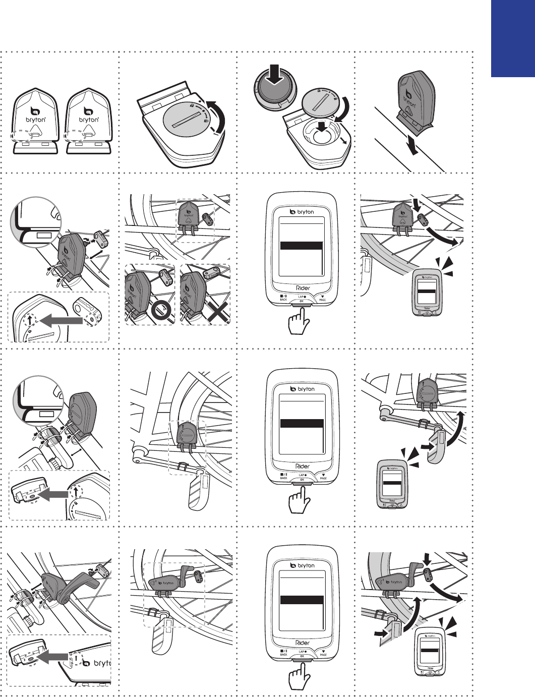
Install the Speed/Cadence/Dual Sensor
(Optional)
CADENCESPEED
SPEED
SPEED
3
mm
SPEED
SPEED
SPEED
SPEED
Speed
Turn Off
Status: active
ID XXXXXXXXX
Rescan
SPEED
Speed
Turn Off
Status: active
ID XXXXXXXXX
Rescan
Cadence
Turn Off
Status: active
ID XXXXXXXXX
Rescan
1
2
3
4
5a
6a
7a
8a
5b
6b
7b
8b
Cadence
Turn Off
Status: active
ID XXXXXXXXX
Rescan
3
mm
CADENCE
Speed/CAD
Turn Off
Status: active
ID XXXXXXXXX
Rescan
5c
6c
7c
8c
Speed/CAD
Turn Off
Status: active
ID XXXXXXXXX
Rescan
3
mm
Appendix
24
NOTE:
To ensur• e optimum performance, do the following:
- Align both sensor and magnet as shown in the illustration (5a / 5b). Pay attention on the
alignment points.
- Ensure the distance between the sensor and the magnet is within 3 mm.
Ensure that both Speed sensor and Speed magnet are installed and aligned horizontally, •
not vertically.
On the initial usage, press the front button to activate the sensor and start pedaling. •
When the sensor detects the magnet, the LED blinks once to indicate the alignment is
correct (the LED blinks only for the rst ten passes after pressing the button).
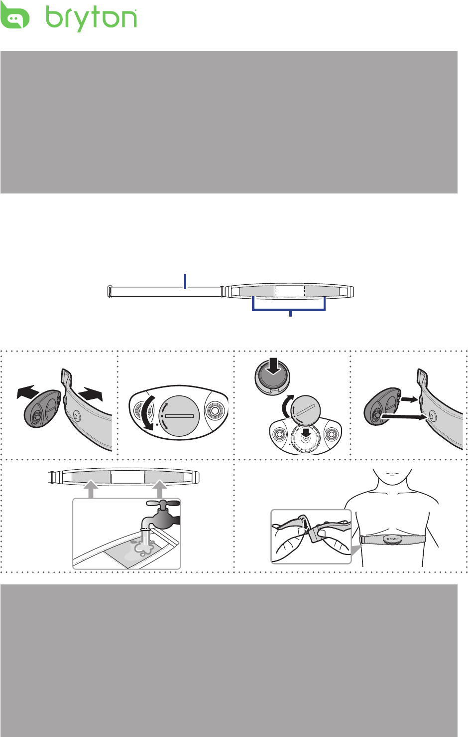
Install Heart Rate Belt (Optional)
Electrodes
Strap
C
L
O
S
E
O
P
E
N
C
L
O
S
E
O
P
E
N
C
L
O
S
E
O
P
E
N
1
2
3
4
5
6
C
L
O
S
E
O
P
E
N
NOTE:
In cold weather, wear appropriate clothing to keep the heart rate belt warm.•
The belt should be worn directly on your body.•
Adjust the sensor position to the middle part of the body (wear it slightly below the •
chest). The Bryton logo shown on the sensor should be facing upward. Tighten the elastic
belt rmly so that it will not turn loose during the exercise.
If the sensor cannot be detected or the reading is abnormal, please warm up for about 5 •
minutes.
If the heart rate belt is not used for a period of time, remove the sensor from the heart •
rate belt.

ENGLISH
Appendix
25
Wheel Size and Circumference
The wheel size is marked on both sides of the tires.
Wheel Size L (mm)
24 x 1.75 1890
24 x 2.00 1925
24 x 2.125 1965
26 x 7/8 1920
26 x 1(59) 1913
26 x 1(65) 1952
26 x 1.25 1953
26 x 1-1/8 1970
26 x 1-3/8 2068
26 x 1-1/2 2100
26 x 1.40 2005
26 x 1.50 2010
26 x 1.75 2023
26 x 1.95 2050
26 x 2.00 2055
700 x19C 2080
700 x 20C 2086
700 x 23C 2096
700 x 25C 2105
700 x 28C 2136
700 x 30C 2170
700 x 32C 2155
700C Tubular 2130
700 x 35C 2168
700 x 38C 2180
700 x 40C 2200
Wheel Size L (mm)
12 x 1.75 935
14 x 1.5 1020
14 x 1.75 1055
16 x 1.5 1185
16 x 1.75 1195
18 x 1.5 1340
18 x 1.75 1350
20 x 1.75 1515
20 x 1-3/8 1615
22 x 1-3/8 1770
22 x 1-1/2 1785
24 x 1 1753
24 x 3/4 Tubular 1785
24 x 1-1/8 1795
24 x 1-1/4 1905
26 x 2.10 2068
26 x 2.125 2070
26 x 2.35 2083
26 x 3.00 2170
27 x 1 2145
27 x 1-1/8 2155
27 x 1-1/4 2161
27 x 1-3/8 2169
650 x 35A 2090
650 x 38A 2125
650 x 38B 2105
700 x 18C 2070

Appendix
26
Basic Care For Your Rider 100
Taking good care of your device will reduce the risk of damage to your device.
Do not drop your device or subject it to severe shock.•
Do not expose your device to extreme temperatures and excessive moisture.•
The screen surface can easily be scratched. Use the non-adhesive generic screen •
protectors to help protect the screen from minor scratches.
Use diluted neutral detergent on a soft cloth to clean your device.•
Do not attempt to disassemble, repair, or make any modications to your device. Any •
attempt to do so will make the warranty invalid.
NOTE: Improper battery replacement may cause an explosion. When replacing a
new battery, use only the original battery or a similar type of battery specied by the
manufacturer. Disposal of the used batteries must be carried out in accordance to the
regulations of your local authority.
For better environmental protection, waste batteries should be collected
separately for recycling or special disposal.

Screen Terminologies
Screen Display Terminology
LapAvSpd lap average speed
LapMaSpd lap maximum speed
L'stLpAvSp last lap average speed
LapDist lap distance
L'stLpDist last lap distance
L'stLapT last lap time
LapAvHR lap average heart rate
LapMaHR lap maximum heart rate
L'LpAvHR last lap average heart rate
L'A'MHR% lap average MHR percentage
L'A'LTHR% lap average LTHR percentage
Str'dRate stride rate
AvStr'dRt average stride rate
MaStr'dRt maximum stride rate
LpAvSt'dR lap average stride rate
LpStr'dAvL lap stride average length
LLpSt'dAvL last lap stride average length
AvSt'dl'gth average stride length
AvgPace average pace
MaxPace maximum pace
L'st1kmP last 1km/mile pace
LapAvP lap average pace
L'stLpAvP last lap average pace
LapMaP lap maximum pace
LAvCAD lap average cadence
ODO odometer
T to Dest Time to Destination
D to Dest Distance to Destination
Alt. Gain Altitude Gain
Alt. Loss Altitude Loss
Appendix

Screen Display Terminology
Sunrise sunrise time
Sunset sunset time
Avg Speed average speed
Max Speed maximum speed
HR heart rate
Avg HR average heart rate
Max HR maximum heart rate
MHR Zone maximum heart rate zone
Avg CAD average cadence
Max CAD maximum cadence
LLAvCAD last lap average cadence
3s Power 3 seconds average power
30s Power 30 seconds average power
LapMaxPW lap maximum power
last lap maximum power
Avg Power average power
LapAvgPW lap average power
LLapAvgPW last lap average power
LLapMaxPW
LapMaxPW lap maximum power
last lap maximum power
Avg Power average power
LapAvgPW lap average power
LLapAvgPW last lap average power
MAP Zone Maximum Aerobic Power Zone
MAP% Maximum Aerobic Power Percentage
FTP Zone Functional Threshold Power
FTP% Functional Threshold Power Percentage
PS L-R Left and Right Pedal Smoothness
TE-LR Left and Right Torque Eectiveness
PB L-R Left and Right Power Balance
Avg PS-LR Average Left and Right Pedal Smoothness
Avg TE-LR Average Left and Right Torque Eectiveness
Avg PB L-R Average Left and Right Power Balance
Max PS-LR
Max TE-LR
Max PB-LR
Maximum Left and Right Pedal Smoothness
Maximum Left and Right Torgue Eectiveness
Maximum Left and Right Power Balance
User's Manual

Table of Contents
2
Getting Started ................ 4
Your Rider 110 ............................. 4
Accessories .................................. 5
Status Icons ................................. 5
Step 1: Charge your Rider 110 ... 6
Step 2: Turn On Rider 110 ........... 6
Step 3: Initial Setup ..................... 6
Step 4: Acquire Satellite
Signals .......................................... 7
Step 5: Ride Your Bike with
Rider 110 ...................................... 7
Reset Rider 110 ........................... 7
Share Your Records ..................... 8
Settings ............................ 9
My Lap ......................................... 9
Display ........................................ 10
Sensors ........................................12
Personalize User Prole ............. 14
Change System Settings ............ 16
View GPS Status ......................... 18
View Software Version ............... 19
Appendix ........................ 20
Specications ............................ 20
Battery Information .................. 21
Install Rider 110 .......................... 22
Install the Speed/Cadence/
Dual Sensor (Optional) ............. 23
Install Heart Rate Belt
(Optional) ................................... 24
Wheel Size and
Circumference ........................... 25
Basic Care For Your Rider 110 ... 26
Table of Contents
Screen Terminologies ............... 27

ENGLISH
Getting Started 3
WARNING
Always consult your physician before you begin or modify any training program. Please read
the details in Warranty and Safety Information guide in the package.
Product Registration
Help us better support you by completing your device registration using Bryton Update Tool.
Go to http://support.brytonsport.com for more information.
Bryton Software
Go to http://brytonsport.com to download free software to upload your personal prole,
tracks and analyze your data on the web.
Australian Consumer Law
Our goods come with guarantees that can not be excluded under the New Zealand and
Australian Consumer Laws. You are entitled to a replacement or refund for a major failure
and for compensation for any other reasonably foreseeable loss or damage. You are also
entitled to have the goods repaired or replaced if the goods fail to be of acceptable quality
and the failure does not amount to a major failure.
Getting Started4
Your Rider 110
Getting Started
This section will guide you on the basic preparations before you start using your Rider 110.
2
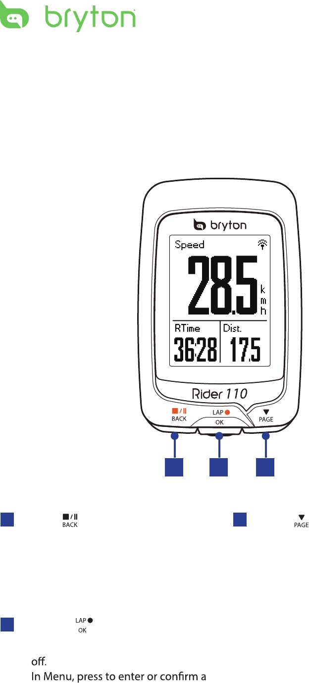
3PAGE ( )
In Menu, press to move down to scroll •
through menu options.
In Meter view, press to switch meter •
screen page. Press and hold to enter
Shortcut page.
1BACK ( )
Press to return to the previous page or •
cancel an operation.
When recording, press to pause •
recording. Press it again to stop
recording.
1 3
2LAP/OK ( )
Press and hold to turn the device on/•
•
selection.
In free cycling, press to start recording.•
When recording, press to mark the lap.•
•
ENGLISH
Getting Started 5
Accessories
The Rider 110 comes with the following accessories:
USB cable• Bike mount•
Optional items:
Heart rate belt• Speed sensor• Cadence sensor•
Speed/Cadence Dual sensor•
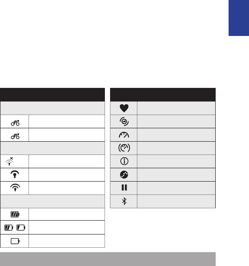
Status Icons
Icon Description Icon Description
Bike Type Heart Rate Sensor Active
1
Bike 1 Cadence Sensor Active
2
Bike 2 Speed Sensor Active
GPS Signal Status Dual Sensor Active
No signal (not xed) Notication
Weak signal Log Record in Progress
Strong signal Recording is paused
Power Status Bluetooth function is enabled
Full battery
/
Half battery
Low battery
NOTE: Only the active icons are displayed on the screen.
•
•Out-front Bike Mount
/- - -
reset
Getting Started6
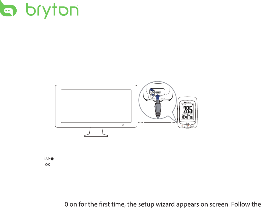
Step 1: Charge your Rider 110
Connect Rider 110 to a PC to charge the battery for at least 3 hours.
Unplug the device when it is fully charged.
Step 2: Turn On Rider 110
Press and hold to turn on the device.
Step 3: Initial Setup
When turning Rider 11
instructions to complete setup.
1. Select the display language.
2. Read and accept the Safety Agreement.
* You may see a white screen when the battery is really low.
Keep the device plugged for several minutes, it will automatically turn-on after battery is properly charged.
ENGLISH
Getting Started 7
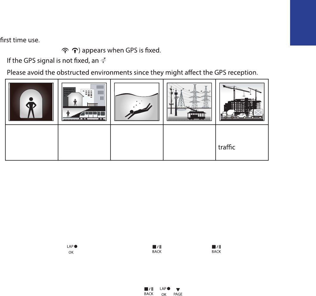
Step 4: Acquire Satellite Signals
Once the Rider 110 is turned on, it will automatically search for satellite signals. It may take
30 to 60 seconds to acquire signals. Please make sure you acquire the satellite signal for the
The GPS signal icon ( /
• icon appears on the screen.
•
Tunnels Inside rooms,
building, or
underground
Under water High-voltage
wires or
television
towers
Construction
sites and heavy
Step 5: Ride Your Bike with Rider 110
Free ride:•
In meter view, measurement starts and stops automatically in sync with the movement
of the bicycle.
Start an exercise and record your data:•
In meter view, press to start recording, press to pause, press again to stop.
Reset Rider 110
To reset the Rider 110, long press all three keys ( / / ) at the same time.

Getting Started
8
Share Your Records
Download Bryton Update Tool
NOTE: Bryton Update Tool can notify you if a new software version or GPS data is available.
The newer GPS data can speed up the GPS acquisition. We highly recommend you to check
for updates every 1-2 weeks.
1. Go to http://www.brytonsport.com/help/start and download Bryton Update Tool.
2. Follow the on-screen instructions to install Bryton Update Tool.
Share Your Tracks to Brytonsport.com
1. Sign up/log in on Brytonsport.com
a. Go to http://www.brytonsport.com/help/start.
b. Register a new account or use your current Bryton account to log in.
NOTE: Bryton account is the email address used to register as a member of brytonsport.com.
2. Connect to PC
Turn on your Rider 110 and connect it to your computer by using USB cable.
3. Share Your Records
a. Go to http://www.brytonsport.com/help/landing. Click “Upload Files” button. Then,
click “Select from Files”.
b. Choose to save as “History”. Then, click “Select and Upload file”.
c. Select FIT files fom Bryton folder in the device.
Settings 9
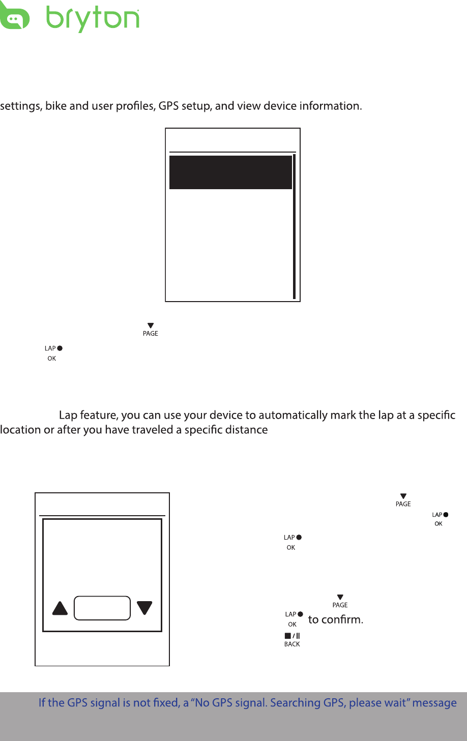
Settings
With the Settings feature, you can customize display settings, sensor settings, system
General
Exercises
Sensors
Profile
Settings
1. In the main screen, press to select Settings.
2. Press to enter the Settings menu.
Smart Lap
With Smart
.
Lap by Location
By Location
Use current
location as
Lap?
Yes
1. In the Settings menu, press to select
Exercises > Smart Lap and press .
2. Press to edit the setting.
3. A “Use current location as Lap ? ”
message appears on the screen. To save
the data, press to select Yes and
press
4. Press to exit this menu.
NOTE:
appears on the screen. Check if the GPS is on and make sure you step outside to acquire
the signal.
Ride Time
Current
Time
Trip Time
ENGLISH
Settings10
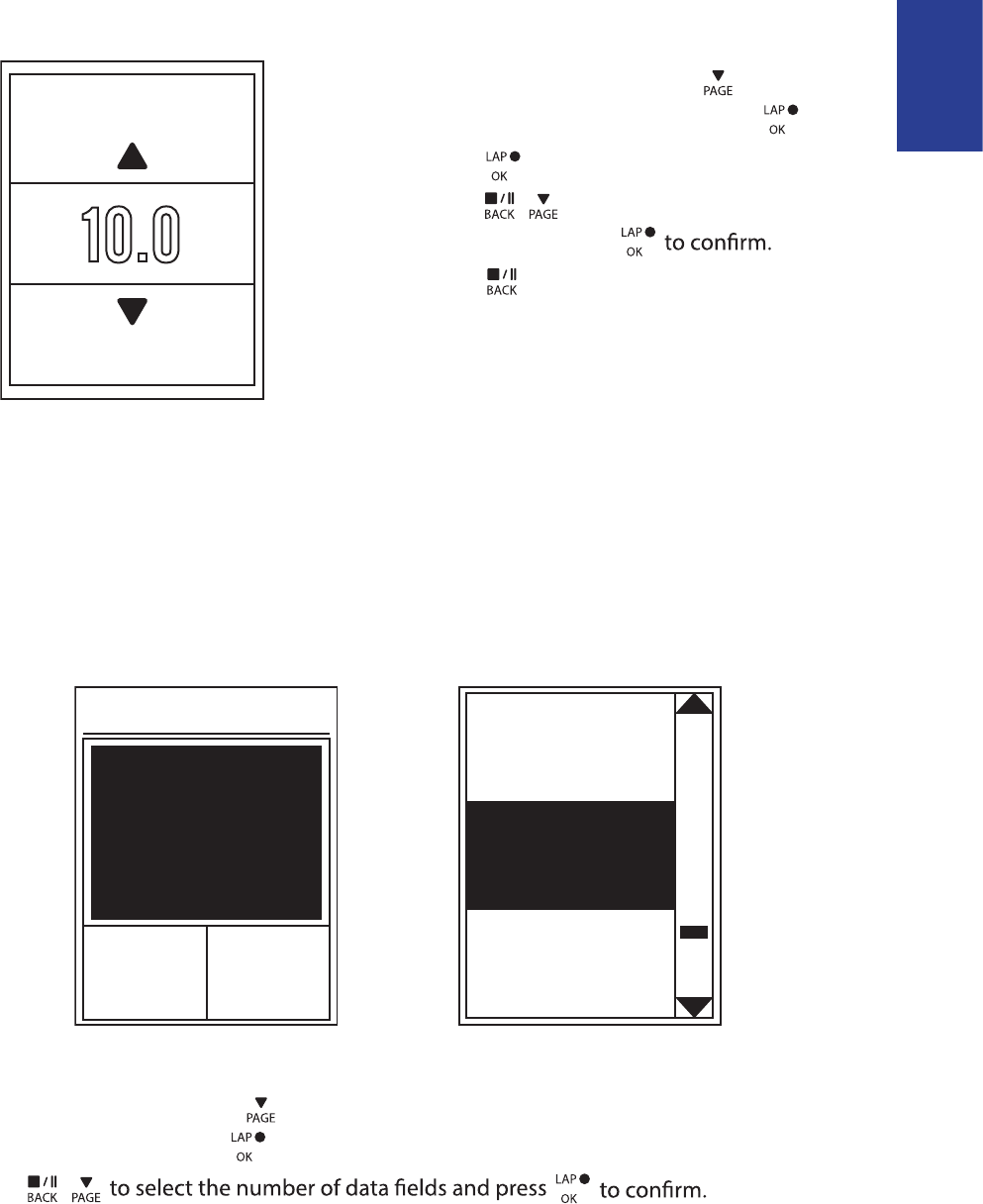
Lap by Distance
By Distance
KM
10.0
1. In the Settings menu, press to select
Exercises> Smart Lap and press .
2. Press to edit the setting.
3. Press / to select your desired
distance and press
4. Press to exit this menu.
Data Page
You can set the data page setting for the Meter, Lap, and Auto Switch. You can also set the
Auto Switch interval setting.
Meter Display
Current
Time
Current
Speed
Total
Distance
3-grid display Item selection
1. In the Settings menu, press to select Exercises> Data Page > Data Page1, Data Page 2,
or and press .
2. Press /
Data Page
Data Page 3
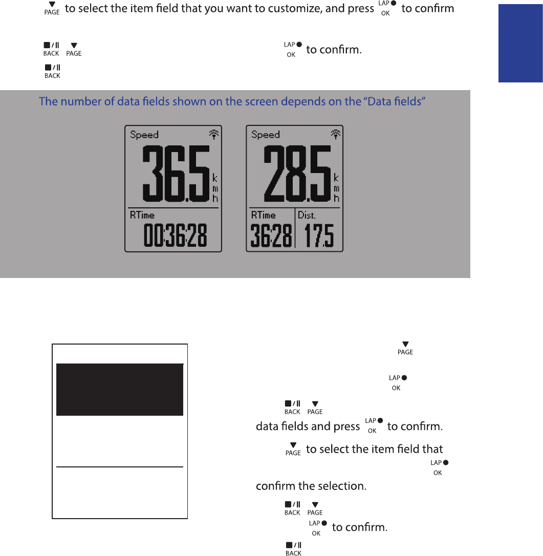
ENGLISH
Settings 11
3. Press
the selection.
4. Press / to select the desired setting and press
5. Press to exit this menu.
NOTE:
selection.
2-grid display 3-grid display
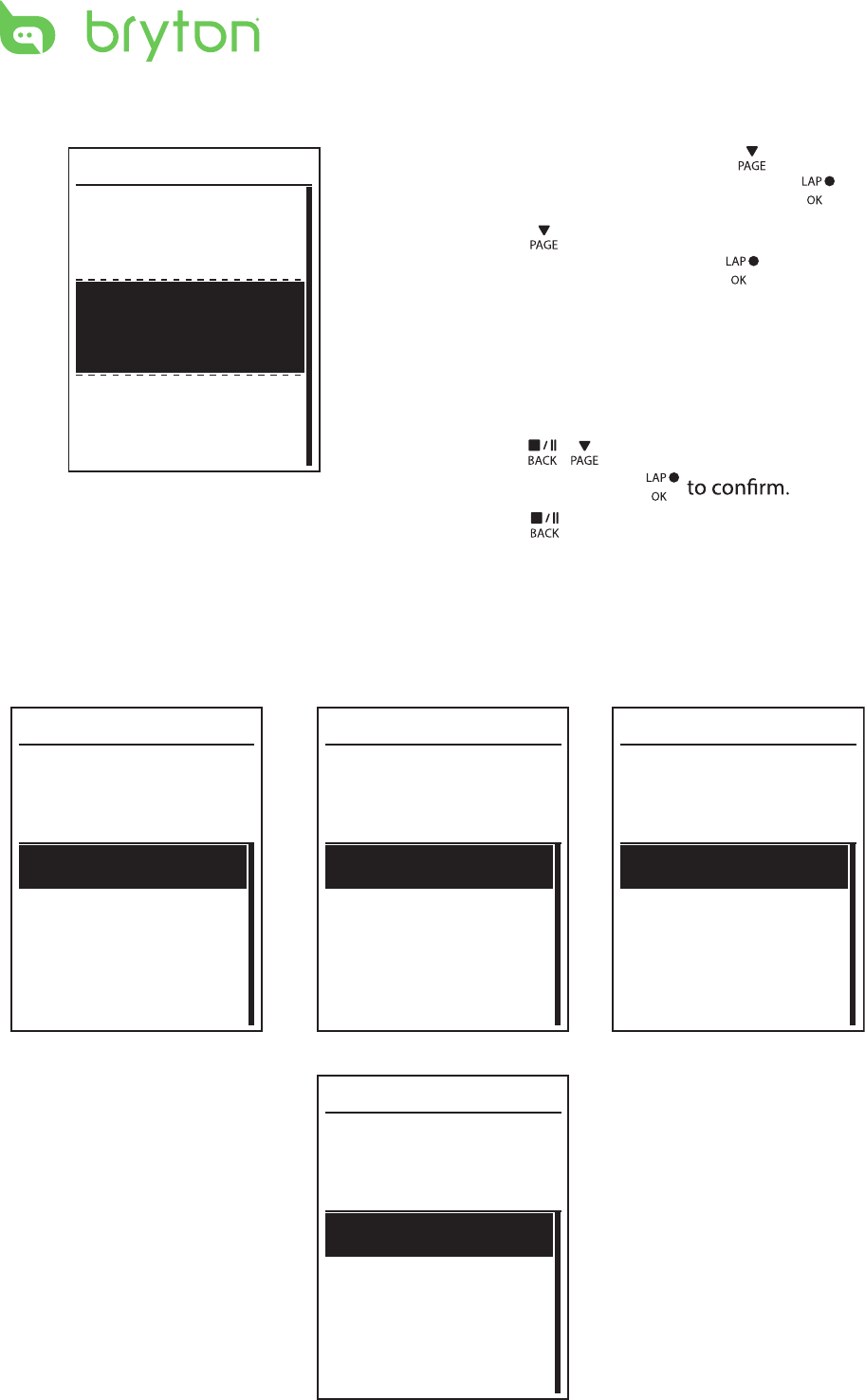
Lap Display
1. In the Settings menu, press to select
Exercises > Data Page> Lap > Data Page1
or Data Page 2 and press .
2. Press / to select the number of
3. Press
you want to customize, and press to
4. Press / to select the desired setting
and press
5. Press to exit this menu.
Cycle Lap
Data Page 1
On
On
Data Page 2
Settings12
Auto Scroll
1. In the Settings menu, press to select
General > Auto scroll and press .
2. Press to select the setting that you
want to change and press to enter its
submenu.
Auto scroll: enable/disable the auto •
switch.
Interval: set the interval time.•
3. Press / to adjust the desired
setting and press
4. Press to exit this menu.
Auto Scroll
Auto Scroll
On
5 sec
Interval
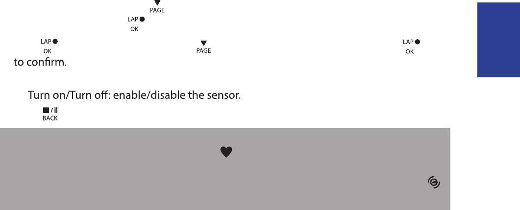
Sensors
You can customize the respective sensor settings such as enable/disable the function or
rescan the sensor for the device.
Heart Rate
Turn Off
Status: active
ID XXXXXXXXX
Rescan
Heart Rate
Speed
Turn Off
Status: active
ID XXXXXXXXX
Rescan
Cadence
Turn Off
Status: active
ID XXXXXXXXX
Rescan
Speed Cadence
Speed/CAD
Turn Off
Status: active
ID XXXXXXXXX
Rescan
Speed/Cadence
ENGLISH
Settings 13
1. In the Settings menu, press to select Sensors > Heart Rate, Speed, Cadence, or
Speed/CAD and press .
2. Press to have more options. Press to select the desired setting and press
Rescan: rescan to detect the sensor. •
•
3. Press to exit this menu.
NOTE:
When the heart rate monitor is paired, the • heart rate icon appears on the main screen.
While pairing your speed/cadence sensor and the heart rate belt, please make sure there •
is no other cadence/speed sensor
within 5 m.
When the cadence sensor is paired, the
cadence sensor icon appears on the main screen.